1. Introduction
Granular materials are ubiquitous in our daily lives and extensively employed across a spectrum of industries such as food, pharmaceutical, agricultural and mining industries. Granular phenomena like yielding and jamming [
1,
2,
3,
4], dilatancy [
5,
6,
7], shear-band localization [
8,
9], history-dependence [
10], and anisotropy [
11,
12] have attracted significant scientific interest over the past decades [
13,
14,
15,
16,
17,
18,
19,
20,
21,
22]. The bulk behavior of granular materials are investigated by using a variety of laboratory element experiments [
23]. One of the important purpose of conducting an element test is to understand the particle characteristics, such as size, shape and size distribution. In addition, it can help to analyze the particle characteristics in the macroscopic bulk response level. These assessments of the particle characteristics are used in the industrial storage and production, for e.g.: design of silos, reactor etc. [
24,
25,
26]. Throughout the test, the element test (macroscopic test) regulates the force (stress) and/or displacement (strain) paths. The most important element test used in the both academia and industry is the shear testing where the sample of a granular material is sheared until the yield point reached and the materials starts to flow. Shear testers are divided into two groups based on the shear zone; direct and indirect shear testers [
23,
25]. The most widely used indirect shear testers are the uniaxial compression tester [
10,
27,
28] and bi-axial shear box [
29,
30,
31].
For accurate material characterization, quality and repeatability of results are essential. Despite the substantial development and study of shear testing methods, significant measurement scatter is still frequent when evaluating the flowability of powders in various labs and conditions [
32,
33,
34,
35,
36]. Prior research has focused on this issue by comparing various devices [
37] and doing round-robin experimental tests on the Jenike tester [
38], Schulze ring shear tester [
32], and Brookfield powder flow tester [
36]. The first round-robin investigation [
38] led to the development of a certified material (CRM-116 limestone powder) and a consistent experimental testing process for identifying the yield locus.
On one batch of limestone powder (CRM-116), Schulze [
32] gathered 60 yield loci using the small Schulze shear tester RST-XS (21 laboratories) and 19 yield loci using the big Schulze shear tester RST-01 (10 labs). Each of these has been compared with the results of the reference Jenike test tester. While there is strong agreement between the RST-01 and RST-XS findings, the Schulze ring shear tester and Jenike shear tester results showed a significant difference (up to 20%). When yield loci from the Brookfield powder flow tester, Schulze ring shear tester, FT4 powder rheometer, Anton Paar Shear cell [
39] and Jenike shear tester are compared, additional studies [
36,
37,
39] discover similar results.
Other investigations [
40,
41] only used one instrument to compare several industrially relevant powders. Furthermore, the stresses used in these comparative investigations are often mild. There is still a lack of knowledge on the flow behavior of powders in various shear devices across a broad stress range. Beyond the scope of earlier initiatives, our collaboration network, EU/ITN CALIPER (
https://caliper-itn.org/), provides the one-of-a-kind opportunity to shed light on the complicated subject of powder yielding and flow. There are 16 partners in the network from both academia and business across Europe. This work was did in Solid Handling Lab in BASF SE, Ludwigshafen am Rhein, Germany. The current study has a number of objectives. First, we aim to examine the accuracy and reproducibility of yield loci measurements among widely utilized shear testers.
This can offer a solid foundation for determining the validity of the testing approach and processes. Second, evaluating powders to study effect of cohesion and bulk density. Understanding the effects of cohesion on powder flowability is important. Finally, a change in the cohesive flow properties of the powder at high temperatures is observed in many industrial applications such as fluidized bed reactors in hot gas filtration, Granulator and dryer. A modified ring-shaped Schulze shear cell was used in this work to measure the flow properties of a powder at elevated temperatures.
To understand the flow properties of a powder, a methodical study has been carried out by testing an industrial cohesive powder (Powder A with the mean particle diameter 2.02μm) in 2 shear testers (the Schulze Ring shear Tester and Anton Paar Powder Cell) at our partners location BASF SE, Germany. In order to maintain the data privacy of the company, the powder name will mention in the entire article as Powder A.
The work is structured as follows: Introduction of the Powder A samples/materials, followed by the details of the devices in experimental perspective and working procedures. Final parts of the work will focus on the experimental results and discussion of those results with focus on shear devices.
2. Materials Description and its Characterization
Powder A is light yellow in color and it is insoluble in water, soluble in alkali and slightly soluble in acid. The Powder A (BASF SE, Germany) is extensively used in different fields to produce chemical products such as paints, coatings, petroleum industry catalyst, pigments in ceramics etc. Median particle size (d50) ranges from 2.02μm, which are cohesive, sticky primary particles that form clumps. The particle size distributions were measured in BASF SE by using laser diffraction (BASF SE) with the dry dispersion unit. The span of the particle size distribution is 14.48 and the average of the particle size (SMD) is 0.981μm. The initial bulk density (bulk density measured directly after filling) is 1258 Kg/m3. The tapped density as well as measured with two different level of tapping (1250 taps and 2500 taps). For 1250 taps the bulk density is 2238 Kg/m3 and for 2500 taps the bulk density is 2276 Kg/m3. Angle of repose (48.20) and sliding angle test have been conducted to learn more about the powder flow and concerns to a variety of application. The sliding angle test was done with two materials hot rolled steel and cold rolled steel. The reason for selecting these materials was that hot rolled steel has a scaly surface finish and cold rolled steel has a semi-roughing surface. In addition, these two materials are widely used in the industrial application. The test were done with two methods, one with (2.5KPa) stress and another without stress. For both methods, the sliding angle for HRS is close to 90 degrees. For CRS, 43 degree without stress and 80 degrees with stress. Based on the value of angle of repose and sliding angle, this Powder A exhibit a poor flow behavior.
3. Experimental Setup
Over the last thirty years, a plethora of testers has been devised to assess the flow characteristics of bulk solids. This development has progressed from semi-automated to fully automated systems. The range of testers now accommodates diverse materials, including powders and granules, while the evolution towards automation has significantly improved efficiency and accuracy in the testing processes. In our case, we present a comparison between measurement of two shear devices, specifically rotation devices (The Schulze Ring Shear Tester and Anton Paar Shear Cell). Two main characteristics of these devices are degree of automation and normal stress regime. Both of these devices are completely automated in most of the operational stages, which strongly reduce the operator influence.
3.1. Schulze Ring Shear Tester – RST-XS.s and RST-01
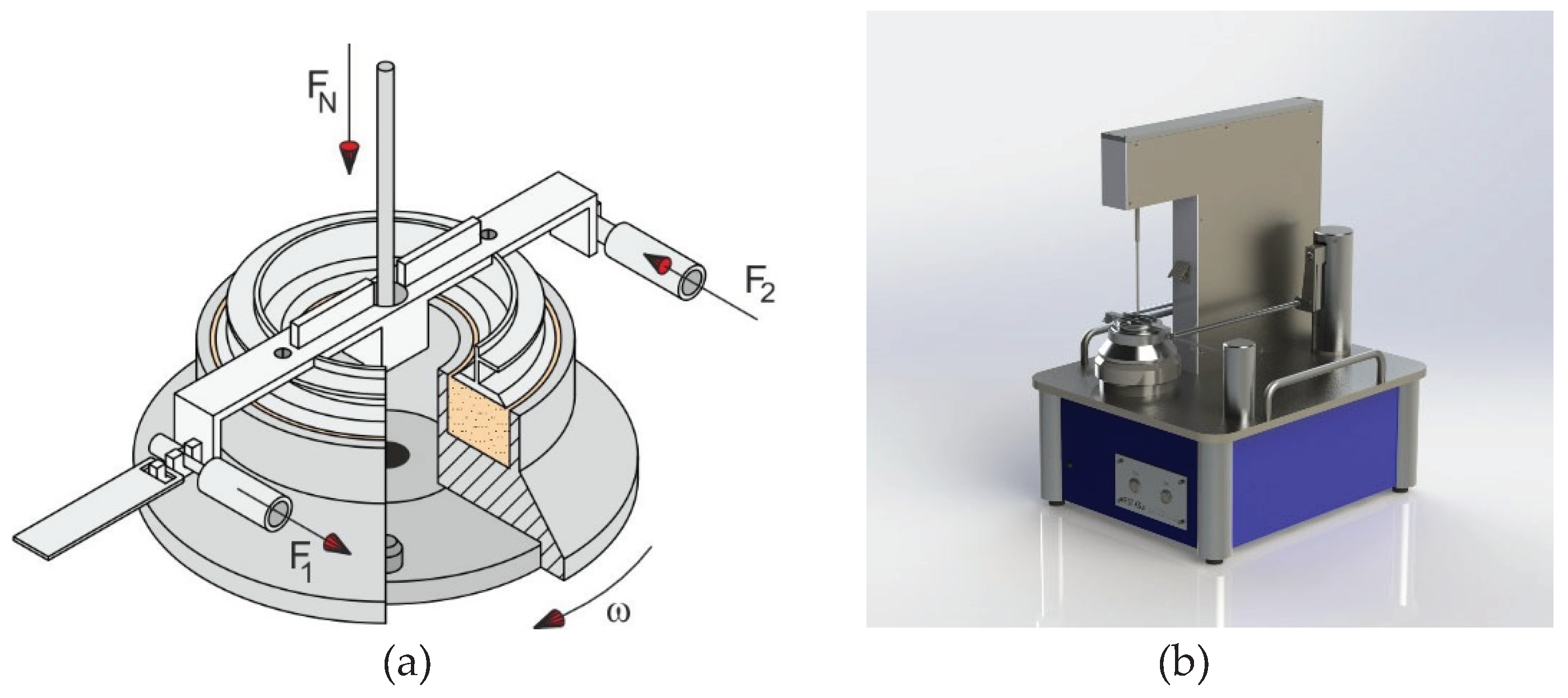
Schulze ring shear tester is a widely used shear device for the powder characterisation. The Schulze ring shear testers are linked to a computer running control software, allowing users to obtain data on yield loci, wall yield loci, attrition, and compression, providing insights into the material's flow properties and mechanical behaviors. A smaller verison of the ring shear tester which exactly working on the same principle is the so-called RST-XS.s with specimen volumes of 30ml (RST-XS.s) and 200ml (RST-01).
The bottom ring of the shear cell, which is ring-shaped (annular) for both testers, contains the bulk solid sample. The bulk solid sample is covered with an annular-shaped lid that is attached at a cross-beam. The cross-beam in the shear cell's rotating axis experiences a normal force, F
N, which is then transferred through the lid to the sample (
Figure 1). As result, the bulk solid is subjected to a normal stress. The counterbalance force, FA, acts in the middle of the cross-beam, formed by counterweights and directed upward, counteracting the gravity forces of the lid, the hanger, and the cross-beam in order to permit small confining stress.
The bottom ring is rotated at an angle to shear the sample, while the lid and the cross-beam are restrained from rotation by two tie-rods attached to the cross-beam. To measure the forces, F1 and F2, acting on the tie-rods, each tie-rod is fastened to a load beam. To stop the bulk solid from sliding over these two surfaces, the shear cell's bottom and the lower side of the lid are both rough. As a result, a shear deformation occurs inside the bulk solid when the bottom ring is rotated in relation to the lid. The deformation of the solid bulk is a consequence of the shearing forces acting on the tie-rods (F1 + F2), resulting in a shear stress directly proportional to these forces. The ASTM standard [60] is followed for every test carried out in this study.
3.2. Anton Paar Shear Tester
The powder shear cell is a tool for evaluating the time-dependent flow behaviour of consolidated powders. Additional attachments offer complete control over humidity and temperature. When creating the Anton Paar Powder Cell (APPC), the Anton Paar firm used a similar idea to assess the powder flow characteristics using Anton Paar MCR Rheometers. A cutting-edge and scientific technology for characterising powders that offers a variety of test procedures is the powder flow cell. Powder performance can be analyzed through simulations and adjustments, with a focus on optimization and other relevant conditions. In this study we are using an 18 ml Anton Paar powder shear cell for the test. It employs standardised test loops and very accurate readings for powder analysis. The method involves applying the Mohr-Coulomb failure envelope theory, where the measured shear stress is compared to the applied normal stress. This theory is commonly used to elucidate materials exhibiting a substantial difference between compressive and tensile strength, particularly applicable to brittle materials.
3.3. Test Procedure
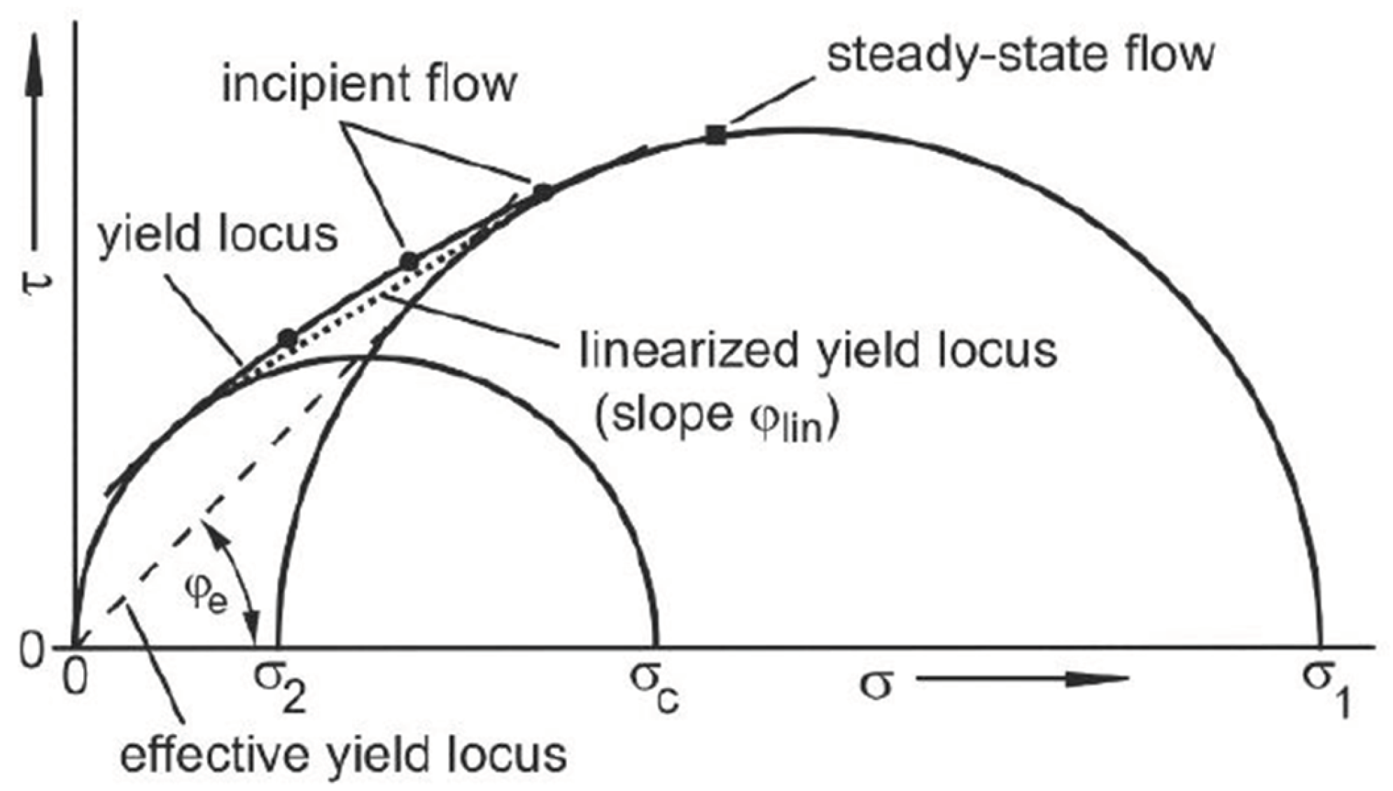
The Schulze ring shear tester and Anton Paar requires one single pre-shear cycle before the first shear point and the steady state is reached(
Figure 2). The primary elements addressed in this study, namely the linearized effective yield locus and yield locus, are illustrated. The depicted values correspond to the measured points at both pre-shear and shear stages.
Then in
Figure 2, during a steady flow a straight line passing through the origin of the σ − τ illustration, by receding toward the large Mohr circle, is the effective yield locus as defined by Jenike [
43]. The slope of the effective yield locus is called the effective angle of internal friction, φe. The largest Mohr stress circle represents the steady-state flow behavior, the angle φe can be considered as a measure of internal friction at steady-state flow. This angle is necessary for silo design according to Jenike's theory. The remaining quantities from yield locus test are the angle of internal fricition which is approximated by the slope angle of linearized yield locus (φ
lin)[
44]. These are all the parameters that describes the flow properties, which can be obtained from the yield locus diagram
Figure 2 [
42]. We have chosen a pre-shear normal stress values between 3.9 and 19.6 kPa.
4. Results
We evaluate the measurements from two shear devices and provide a comprehensive overview of the test findings' repeatability and reproducibility. When comparing the yield loci from various testing, powder A which was introduced in the above section is used as a reference powders. We analyze the previously mentioned powder based on parameters such as bulk density, angle of internal friction, cohesive strength, steady-state angle of internal friction, effective angle of internal friction, and flow function.
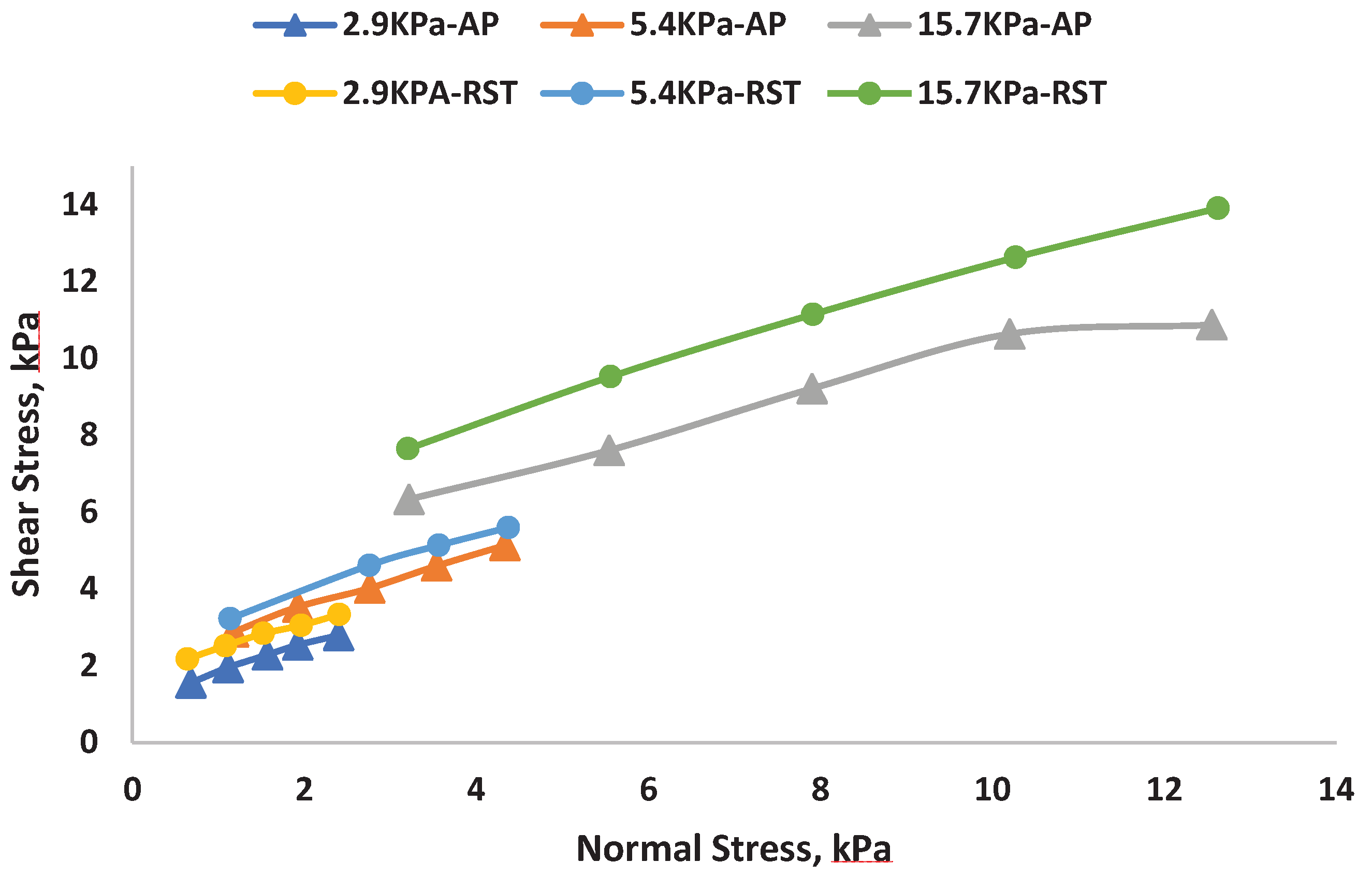
For both devices, repeatability is very high, with the standard deviation within the symbol size. Despite using same pre-shear normal stresses, the yield loci recorded by the two devices for the powder A show average deviation. Results from APPC are consistently lower than results from the RST-Xs.s. The instruments does not display a linear increase in slope or a decreasing slope as the normal stress increases. (
Figure 3).
Our findings indicate that the powder response in the case of cohesive material may be impacted by the system size as the sole distinction between RST-XS and APPC is the size of the shear cell.
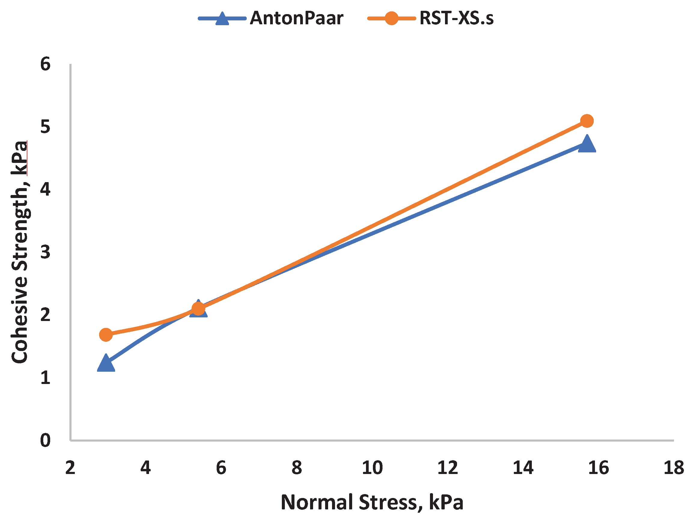
To validate the consistency of results from both shear devices, we extrapolate the linearized yield loci and compare the angle of internal friction, as well as the cohesive strength (intersection of the linearized yield locus on the y-axis), for the two reference powders (
Figure 4 and
Figure 5).
Data from different shear testers are interpreted in diverse ways. Using the default software and the pro-rating procedure, RST-XS.s and APCC results are both linearized. For Powder A, we get a good agreement between the RST-XS.s and APCC for the cohesive strength, c. In
Figure 4, we plot the cohesive strength against the pre-shear normal stress. As expected, the cohesive strength values at given stress level are higher for powder A. Based on the theory, the smaller particles with higher density are the strongest cohesive forces and acting most effectively on each other. A similar observation is also found for the angle of internal friction as shown in
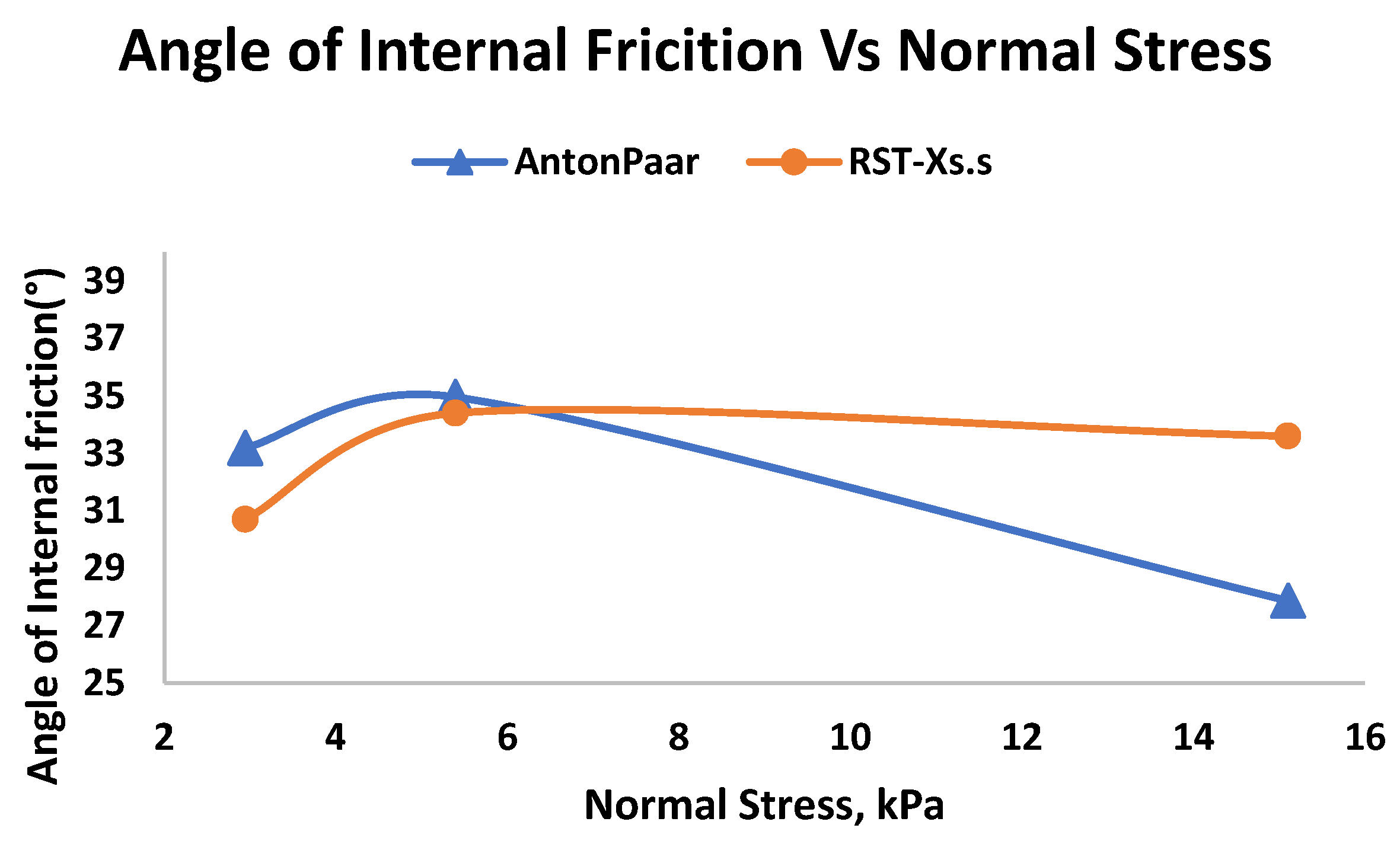
Figure 5 Angle of Internal Friction is plotted against Normal Stress using RST.XS.s and APCC but the value of φ obtained from the APCC is lower than that of RST-XS.s, but still within the fluctuation range. In addition to the internal friction angle, it is necessary to check the cohesivity, which is the coordinates at the origin extrapolated from the linearized yield locus, and gives an indication of the resistance/strength of the powder under zero confining stress (σ
n).
The angle of internal friction describes how the powder can withstand applied shear stress before undergoing plastic flow, which is intent on from the linearized yield locus as shown in
Figure 5. Generally, for the cohesive powders, the yield locus is non-linear but the linearized the yield locus can still be used to evaluate the angle of internal friction for the studied stress ranges. Utilizing the assessed values above, a predominant property is identified that governs the maximum bulk friction of the powder based on a specific pre-consolidation history. All internal friction angles are derived from the linearized yield loci.
In
Figure 5, we plot the angle of internal friction versus normal stress at three different pre-shear normal stress. Within the stress studied, there is no clear dependence of the angle of internal friction on the normal stress. To check whether there is any impact on the devices, we have tested in the RST.XS.s and APPC. The flow characteristics results of the powder A are very similar in both devices. The agreement suggests that the observed behavior is attributed to material properties (Powder A) rather than being dependent on the specific shear device used. The possible explanation for this interesting behavior on bulk friction is that particle of different sizes have same shape but different surface roughness/asperity but this needs to be studied. Another possibility is the battling between the inter-particle cohesion and inter-particle friction (inflenced by shape). In this case, the particles are small in size, the inter-particle cohesion between the particle governs the flow behavior and increasing the shear resistance. Moreover, when the sample is subjected to confinement below a specific stress level, a low inter-particle cohesion can result in a higher bulk density. This, in turn, reduces the available free space for particle movement. In such cases, the significance of geometrical interlocking becomes crucial.
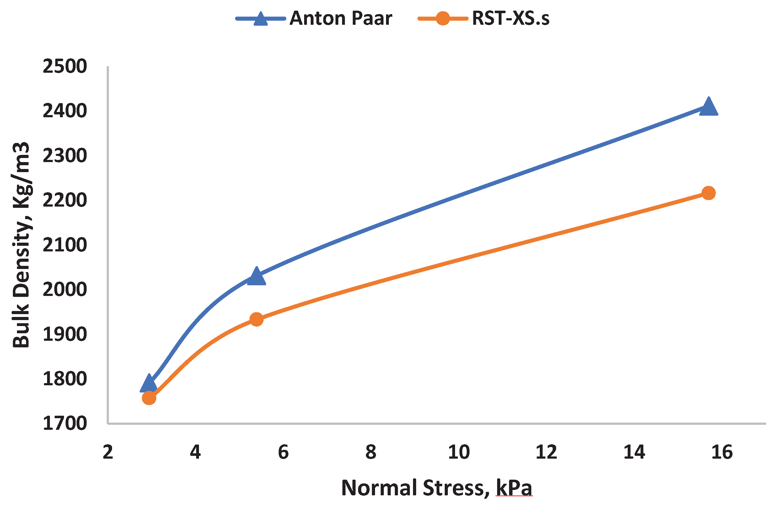
We examine how the bulk density of powder A varies with respect to normal stress and particle size.
Figure 6 is displays data and shows the increasing trend in bulk density for normal stress.
The bulk density of powder A increases with an increase in normal stress at varying range. When the level of normal stress ranges are increasing, the range of bulk density is also steadily increasing for both the devices. We attribute this tendency to the wider particle size distribution, as indicated by the large span value of 14.48. A wider particle size distribution allows easy rearrangement of the packing structure when applying external load. The presence of cohesive forces, such as van der Waals forces, in elementary particles is widely acknowledged, and additional gravitational forces may also contribute to this phenomenon. Since liquid bridging and other forces are anticipated to be minimal in powder A' comparatively dry state, the bulk density will high due to the formation of clusters and many voids caused by the dry cohesive interaction.
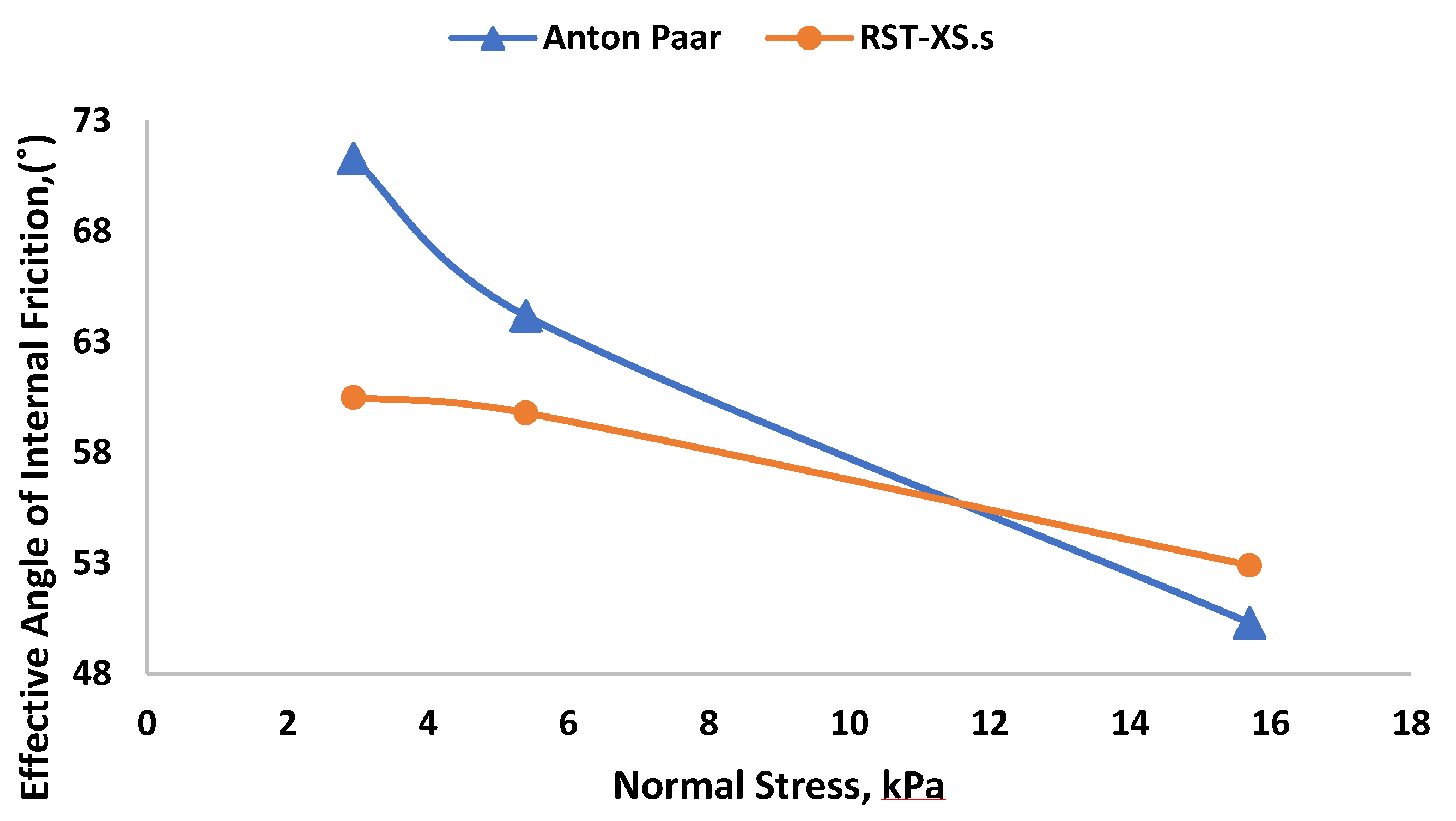
Effective angle of internal friction represents influences the positioning of the Mohr circle, providing insights into the shear strength and stress conditions within the material. The relationship between these two concepts is crucial for analyzing and predicting the mechanical behavior of materials under various loading scenarios. Additionally, this characteristic is important in designing the hopper angle to achieve high flow rates in the silo. In
Figure 7, the effective angle of internal friction is plotted versus the normal stress. Within the stress investigated, effective angle of internal friction decreases with increasing normal stress.
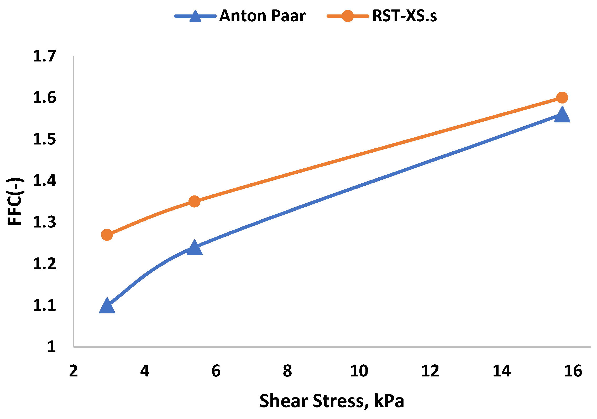
We analyze the results to assess powder flowability by examining the flow function. This evaluation helps us understand how a specific powder would behave or flow under a given major consolidation stress (
Figure 8 and
Figure 9). This is also significant for the designing the outlet diameter of a silo [
45]. In
Figure 8, we plot the unconfined yield strength against the major principal consolidation stress. As we can see, our powder flowability values lies in the range of cohesivity. In the stress range we investigated, unconfined yield strength increases for all stress range with increasing principal consolidation stress.
As one can see from the
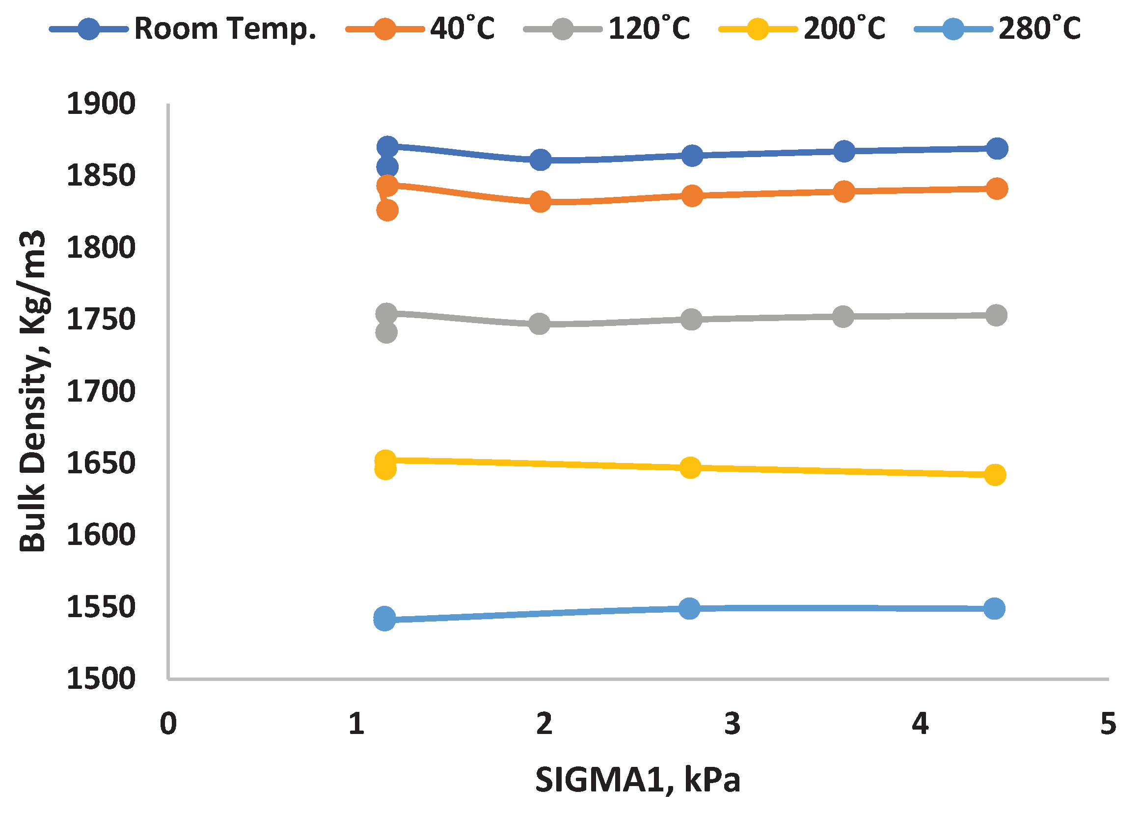
Figure 6 Bulk density is plotted against normal stress using RST.XS.s and APCC (bulk density), the bulk density is increasing in a large range when normal stress rate is increased. In order to get deeper insights on this interesting behavior, we tested the shear cell experiments in heated chamber with different temperatures. A Schulze ring shear cell was placed inside the heated closed chamber with temperature monitor. 5.4 kPa was applied as a normal stress for all the shear cell experiments. As one can see in
Figure 10, the graph as plotted against bulk density and σ
1 for different temperature (Room temperature, 40
). When the temperature increases, the bulk density is continuously decreasing. It is due to lot of reasons such as shape, size, environmental condition and mechanism behind chemistry. Normally cohesive powder, in which attractive inter-particle force outweigh its particle weigh, tends to produce an open structure supported by the inter-particle force. This result is therefore a relatively low bulk density. Because the chemical structures formed are not robust, they are prone to collapse under low pressure.
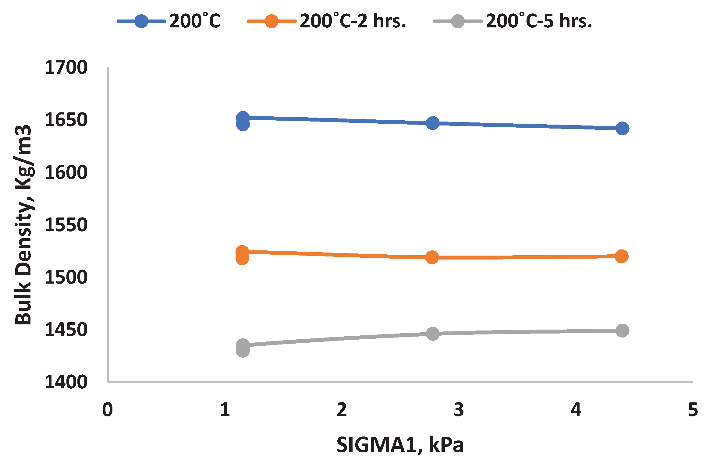
In order to verify the decreasing trend of bulk density for different temperature, we conducted the same ring shear test in a heated chamber for a single temperature (200
) and it is maintained for two different time range. One was maintained at 200
for 2hrs and the other one is maintained at 200
for 5hrs. The graph (
Figure 11) is generated by plotting bulk density against σ
1 for a normal stress rate of 5.4 kPa.
In both tests, the bulk density shows the anticipated decreasing trend. This pattern indicates an increase in aggregation content, resulting in decreased bulk density at a normal stress rate of 5.4 kPa. Tillage operations, such as ploughing, typically decrease bulk density and increase pore space, impacting the structure of the material. Another contributing factor may be the small size and wider particle size distribution of powder A, reducing the likelihood of breakdown and fresh face formation (reduction process) and consequently leading to a long-term reduction in bulk density at a constant temperature.
5. Conclusion and Outlook
In this investigation, we have methodically investigated the powder flow behavior of powder A samples in two shear testers at various confining stress levels. The main objective was to comprehend the relationship between macroscopic, bulk properties like bulk density, cohesive strength, shear resistance (characterized by the effective angle of internal friction and the internal friction at steady state flow) and microscopic, bulk properties like particle size and contact cohesion. Two shear testers are given highly reproducible good results with deviation in the range of 20% among each other. APCC give the high standard deviation than Ring shear tester. The yield loci obtained from the Schulze ring shear tester (RST-01) remain consistently slightly higher than results from Anton Paar Powder Cell. From a practical perspective, this conservative tendency is safer for silo design. In summary, automated devices reduce operator influence, and correct interpretation of results is crucial. Protocol differences can significantly affect deviations in operator and material response. However, if established qualitative trends are consistent across different testers, it enhances the reliability of the outcomes.
Powder A is tested over a wide range of normal loads (5, 20 and 35 kPa). Size and stress factors, bulk density, cohesion are recognized for their substantial influence on bulk flow. Typically, an increase in load results in higher power, indicating a more delicate and pronounced effect on particle behavior. On the other hand, the internal friction angle does not seem to be affected by normal stress (at least within the range considered here), effective interior angle of friction and internal friction show a decreasing trend for different normal stress. Bulk density increases monotonically for powder A in both the shear devices. Interlocking between particles due to surface roughness and shape dominates the bulk behavior of powder A, while cohesion is a key factor in determining the shear strength of fine powders. The geometric interlocking effect is enhanced by increasing the bulk density in the case of powder samples. For a deeper study, we tested the shear cell experiments for a powder with different range of temperature. For heated case, bulk density is steadily decreasing and it’s due to the reduction process.
For the sake of completeness, powder flow behavior is also considered as it relates to silo design. Overall, for smaller size particle (Powder A), the flowability increases as the normal stress increases (the powder flows more easily). For larger particles, the fluidity tends to be more pronounced. The current study marks the beginning of the collection of experimental data, which could be further enriched in the future with data from many other materials of industrial and academic interest. Our speculation about the interesting aggregation and frictional behavior of the bulk with increasing particle size requires further investigation. Additionally, this experimental database serves as a foundation for designing methods, such as silo methodologies, and stands as a benchmark for future experimental research endeavors. Last but not least, the experimental data presented here are required for particle model and simulation, especially for DEM contact model development, calibration, validation, and element test (shear test) simulation.
Funding
This project has received funding from the European Union’s Horizon 2020 research and innovation program under the Marie Skłodowska-Curie grant agreement No. 812638 (CALIPER).
Institutional Review Board Statement
Not applicable.
Informed Consent Statement
Not applicable.
Acknowledgments
I would like to thank the BASF lab assistants Chayeene Kohler and Timo Osswaald for helping in preparing the materials, shear cell tester and heated chamber.
Conflicts of Interest
Author declare no conflict of interest
References
- Kumar, N.; Luding, S. Memory of jamming–multiscale models for soft and granular matter. Granul. Matter 2016, 18, 1–21. [Google Scholar] [CrossRef]
- Luding, S. So much for the jamming point. Nat. Phys. 2016, 12, 531–532. [Google Scholar] [CrossRef]
- Liu, A.J.; Nagel, S.R. Jamming is not just cool any more. Nature 1998, 396, 21–22. [Google Scholar] [CrossRef]
- Bi, D.; Zhang, J.; Chakraborty, B.; Behringer, R.P. Jamming by shear. Nature 2011, 480, 355–358. [Google Scholar] [CrossRef] [PubMed]
- Yang, Y.; Fei, W.; Yu, H.-S.; Ooi, J.; Rotter, M. Experimental study of anisotropy and non-coaxiality of granular solids. Granul. Matter 2015, 17, 189–196. [Google Scholar] [CrossRef]
- van Hecke, M. Jamming of soft particles: geometry, mechanics, scaling and isostaticity. J. Physics: Condens. Matter 2009, 22, 033101. [Google Scholar] [CrossRef]
- E Cates, M.; Haw, M.D.; Holmes, C.B. Dilatancy, jamming, and the physics of granulation. J. Physics: Condens. Matter 2005, 17, S2517–S2531. [Google Scholar] [CrossRef]
- Alshibli, K.A.; Sture, S. Shear Band Formation in Plane Strain Experiments of Sand. J. Geotech. Geoenvironmental Eng. 2000, 126, 495–503. [Google Scholar] [CrossRef]
- Singh, A.; Magnanimo, V.; Saitoh, K.; Luding, S. Effect of cohesion on shear banding in quasistatic granular materials. Phys. Rev. E 2014, 90, 022202. [Google Scholar] [CrossRef]
- Thakur, S.C.; Ahmadian, H.; Sun, J.; Ooi, J.Y. An experimental and numerical study of packing, compression, and caking behaviour of detergent powders. Particuology 2014, 12, 2–12. [Google Scholar] [CrossRef]
- Radjai, F.; Jean, M.; Moreau, J.J.; Roux, S. Force distributions in dense two-dimensional granular systems. Physical review letters 1996, 77, 274. [Google Scholar] [CrossRef] [PubMed]
- Majmudar, T.S.; Behringer, R.P. Contact force measurements and stress-induced anisotropy in granular materials. Nature 2005, 435, 1079–1082. [Google Scholar] [CrossRef] [PubMed]
- Luding, S. Cohesive, frictional powders: contact models for tension. Granul. Matter 2008, 10, 235–246. [Google Scholar] [CrossRef]
- Luding, S. Shear flow modeling of cohesive and frictional fine powder. Powder Technol. 2005, 158, 45–50. [Google Scholar] [CrossRef]
- Luding, S. Anisotropy in cohesive, frictional granular media. J. Physics: Condens. Matter 2005, 17, S2623–S2640. [Google Scholar] [CrossRef]
- Alonso-Marroquín, F.; Herrmann, H.J. Ratcheting of Granular Materials. Phys. Rev. Lett. 2004, 92, 054301. [Google Scholar] [CrossRef]
- Tomas, J. Product Design of Cohesive Powders– Mechanical Properties, Compression and Flow Behavior. Chem. Eng. Technol. 2004, 27, 605–618. [Google Scholar] [CrossRef]
- GDR MiDi gdrmidi@ polytech. univ-mrs. fr http://www. lmgc. univ-montp2. fr/MIDI/, 2004. On dense granular flows. The European Physical Journal E, 14, pp.341-365.
- Wolf, B.; Scirocco, R.; Frith, W.; Norton, I. Shear-induced anisotropic microstructure in phase-separated biopolymer mixtures. Food Hydrocoll. 2000, 14, 217–225. [Google Scholar] [CrossRef]
- Radjai, F.; Roux, S.; Moreau, J.J. Contact forces in a granular packing. Chaos: Interdiscip. J. Nonlinear Sci. 1999, 9, 544–550. [Google Scholar] [CrossRef]
- Cundall, P.A. Numerical experiments on localization in frictional materials. Arch. Appl. Mech. 1989, 59, 148–159. [Google Scholar] [CrossRef]
- Savage, S.B.; Hutter, K. The motion of a finite mass of granular material down a rough incline. J. Fluid Mech. 1989, 199, 177–215. [Google Scholar] [CrossRef]
- Schwedes, J. Review on testers for measuring flow properties of bulk solids. Granul. Matter 2003, 5, 1–43. [Google Scholar] [CrossRef]
- Jenike, A. Quantitative design of mass-flow bins. Powder Technol. 1967, 1, 237–244. [Google Scholar] [CrossRef]
- Schwedes, J. Measurement of flow properties of bulk solids. Powder Technol. 1996, 88, 285–290. [Google Scholar] [CrossRef]
- Schulze, D. Time- and Velocity-Dependent Properties of Powders Effecting Slip-Stick Oscillations. Chem. Eng. Technol. 2003, 26, 1047–1051. [Google Scholar] [CrossRef]
- Russell, A.; Müller, P.; Shi, H.; Tomas, J. Influences of loading rate and preloading on the mechanical properties of dry elasto-plastic granules under compression. AIChE J. 2014, 60, 4037–4050. [Google Scholar] [CrossRef]
- Imole, O.I.; Paulick, M.; Magnanimo, V.; Morgeneyer, M.; Montes, B.E.C.; Ramaioli, M.; Kwade, A.; Luding, S. Slow stress relaxation behavior of cohesive powders. Powder Technol. 2016, 293, 82–93. [Google Scholar] [CrossRef]
- Morgeneyer, M.; Brendel, L.; Farkas, Z.; Kadau, D.; Wolf, D.E.; Schwedes, J. Can one make a powder forget its history? arXiv 2003. [Google Scholar]
- Morgeneyer, M.; Schwedes, J. Investigation of powder properties using alternating strain paths. Task Quarterly 2003, 7, 571–578. [Google Scholar]
- Feise, H.J.; Schwedes, J. Investigation of the Behaviour of Cohesive Powder in the Biaxial Tester. KONA Powder Part. J. 1995, 13, 99–103. [Google Scholar] [CrossRef]
- Schulze, D. Round robin test on ring shear testers. Adv. Powder Technol. 2011, 22, 197–202. [Google Scholar] [CrossRef]
- Kamath, S.; Puri, V.; Manbeck, H.; Hogg, R. Flow properties of powders using four testers — measurement, comparison and assessment. Powder Technol. 1993, 76, 277–289. [Google Scholar] [CrossRef]
- Kamath, S.; Puri, V.; Manbeck, H. Flow property measurement using the Jenike cell for wheat flour at various moisture contents and consolidation times. Powder Technol. 1994, 81, 293–297. [Google Scholar] [CrossRef]
- Freeman, R. Measuring the flow properties of consolidated, conditioned and aerated powders — A comparative study using a powder rheometer and a rotational shear cell. Powder Technol. 2007, 174, 25–33. [Google Scholar] [CrossRef]
- Berry, R.; Bradley, M.; McGregor, R. Brookfield powder flow tester – Results of round robin tests with CRM-116 limestone powder. Proc. Inst. Mech. Eng. Part E: J. Process. Mech. Eng. 2014, 229, 215–230. [Google Scholar] [CrossRef]
- Koynov, S.; Glasser, B.; Muzzio, F. Comparison of three rotational shear cell testers: Powder flowability and bulk density. Powder Technol. 2015, 283, 103–112. [Google Scholar] [CrossRef]
- R. J. Akers and R. Commission of the European Communities. Directorate-General for Science, “The certification of a limestone powder for Jenike shear testing : CRM 116 : final report,” p. 149, 1992.
- Salehi, H.; Sofia, D.; Schütz, D.; Barletta, D.; Poletto, M. Experiments and simulation of torque in Anton Paar powder cell. Part. Sci. Technol. 2018, 36, 501–512. [Google Scholar] [CrossRef]
- Teunou, E.; Fitzpatrick, J.; Synnott, E. Characterisation of food powder flowability. J. Food Eng. 1999, 39, 31–37. [Google Scholar] [CrossRef]
- Fitzpatrick, J.; Barringer, S.; Iqbal, T. Flow property measurement of food powders and sensitivity of Jenike’s hopper design methodology to the measured values. J. Food Eng. 2004, 61, 399–405. [Google Scholar] [CrossRef]
- Schulze, D. Flow properties of powders and bulk solids (fundamentals). Powder Technol 2010, 65, 321–333. [Google Scholar]
- Kwade, A.; Schulze, D.; Schwedes, J. Determination of the stress ratio in uniaxial compression tests-Part 1. Powder Handling and Processing 1994, 6, 61–65. [Google Scholar]
-
Powders and Bulk Solids; Springer Science and Business Media LLC: Dordrecht, GX, Netherlands, 2007; ISBN 9783030767198.
- Schulze, D.; Schulze, D. Beispiele gemessener Fließeigenschaften; Pulver und Schüttgüter: Fließeigenschaften und Handhabung, 2019; pp. 263–283. [Google Scholar]
|
Disclaimer/Publisher’s Note: The statements, opinions and data contained in all publications are solely those of the individual author(s) and contributor(s) and not of MDPI and/or the editor(s). MDPI and/or the editor(s) disclaim responsibility for any injury to people or property resulting from any ideas, methods, instructions or products referred to in the content. |
© 2024 by the authors. Licensee MDPI, Basel, Switzerland. This article is an open access article distributed under the terms and conditions of the Creative Commons Attribution (CC BY) license (http://creativecommons.org/licenses/by/4.0/).
