1. Introduction
In the exciting field of mechatronics and robotics, the demand for improving the performance and efficiency of technical systems has led to research into innovative drive technologies. Pneumatic artificial muscles (PAMs) have emerged as a promising solution, offering a unique combination of flexibility, lightweight design, and inherent compliance. PAMs are soft and flexible linear pneumatic actuators that have been developed to mimic the actuation of human muscles [
1]. Inspired by the human musculoskeletal system, these pneumatic actuators provide the opportunity to create advanced mechatronic and robotic systems that can replicate and amplify human-like movements. Their potential to revolutionize this field by providing an adaptive and energy-efficient way of actuation leads to wide applications in industrial devices, robotic platforms, and medical human-friendly orthopaedic aid devices [
2]. As biologically inspired actuators, PAMs have the potential to become a prime candidate for implementation in future robotic applications [
3]. PAMs have shown significant promise as an alternative to electric motors for future robotic applications where safety, compliance, and lower weight are prioritized over high precision and force such that they can become the preferred solution for robotic devices with a focus on safe human-robot interactions [
4]. PAMs have a transformative role in shaping the future of intelligent, responsive machines that are suitable for collaborative applications, where robots work alongside humans in shared workspaces. Pneumatic muscles, with their features such as adaptability, elasticity and lightness, are well-suited for integration into bionic systems. These systems involve biologically inspired designs wherein the utilization of biological methods and processes from nature enhances engineering systems and modern technological products. [
5]. Unfortunately, owing to their highly nonlinear and time-varying nature, controlling the motion or force of pneumatic muscles still represents a great challenge. Consequently, various control methodologies have been employed to control different robotic systems, manipulators, and orthopedic devices driven by artificial muscles [
6,
7,
8,
9,
10,
11,
12].
The subsequent sections introduce various experimental systems actuated by PAMs, covering autonomous vehicles, walking robots, orthopaedic devices, automated systems, and mechatronic systems—common application areas for fluidic muscles.
2. Materials and Methods
This section presents several unique demonstrative example of systems actuated by PAMs, designed as test models within the field of pneumatic systems and the automatic control. First, the robotic systems will be presented: the design and construction of four legged walking robot and a planar manipulator arm with 1 DOF actuated by PAMs. Then two autonomous vehicles powered by PAMs were introduced. Following that, two unique mechatronic systems are described: ball on beam system and ball on plate system which fall into the category of unstable, under-actuated, multivariable systems with highly nonlinear dynamics. Finally, the design and construction of a prototype of an actively powered ankle foot orthosis is described, which enables the appropriate function required in the rehabilitation of patients and the loss of mobility.
2.1. Robotic Systems
Inspired by human musculature, pneumatic muscle actuators (PMAs) are revolutionizing robotics by offering lifelike movements. These actuators closely resemble the way human muscles move and flex, making them almost an ideal choice for creating realistic and sensitive robotic movements. This unique design, with its advantages of lightweight construction, high power-to-weight ratio, and environmental compliance, allows PMAs to achieve exceptional performance in producing smooth, precise movements for robots. The capabilities of PMAs unlock a new level of agility and adaptability in robots, particularly walking robots navigating challenging terrains. By facilitating robots to display more natural and human-like movements, PMAs lead to advancements in various applications, initiating a new era of innovation in robotics.
Mobile robotics, a fascinating and rapidly evolving field, encompasses various inspiring research areas, including the development of robots that mimic biological systems like humans and animals. This multidisciplinary domain, demanding expertise in mechanical, electronic, and software engineering, has given rise to a fascinating subfield such as legged robots. This type of robots offers distinct advantages over their wheeled or tracked counterparts. Unlike the limitations of wheels on rough terrains, legged robots, inspired by their biological counterparts, can adjust their gait and step length, making them highly adaptable and mobile in dynamic environments. The fascination with machines that mimic nature drives the development of walking robots, making them one of the most complex and captivating branches of engineering. Inspired by the biomechanics of humans, animals (dogs, horses, insects, etc.), and even centipedes, researchers have created a diverse range of walking robots, including mono-pedal, bipedal, quadrupedal, hexapod, and octopod designs [
13,
14,
15,
16,
17,
18]. This biomimetic approach often utilizes pneumatic muscles, whose performance closely resembles human muscles, making them a natural choice for actuating these walking robots. While wheeled robots operate effectively on flat terrain with their simpler design and higher speeds, they struggle in challenging environments. Conversely, walking robots, inspired by nature, dominate in these situations owing to their superior mobility, adaptability, and stability. This is achieved by utilizing pneumatic muscle actuators, which mimic the efficiency and natural movement of biological muscles. As evidence of their capabilities, autonomous quadruped robots powered by such actuators have been successfully implemented in practice, demonstrating the vast range of potential applications in harsh environments. Below is an example of an autonomous quadruped robot actuated by PAMs.
2.1.1. Four-Legged Walking Robot Actuated by PAMs
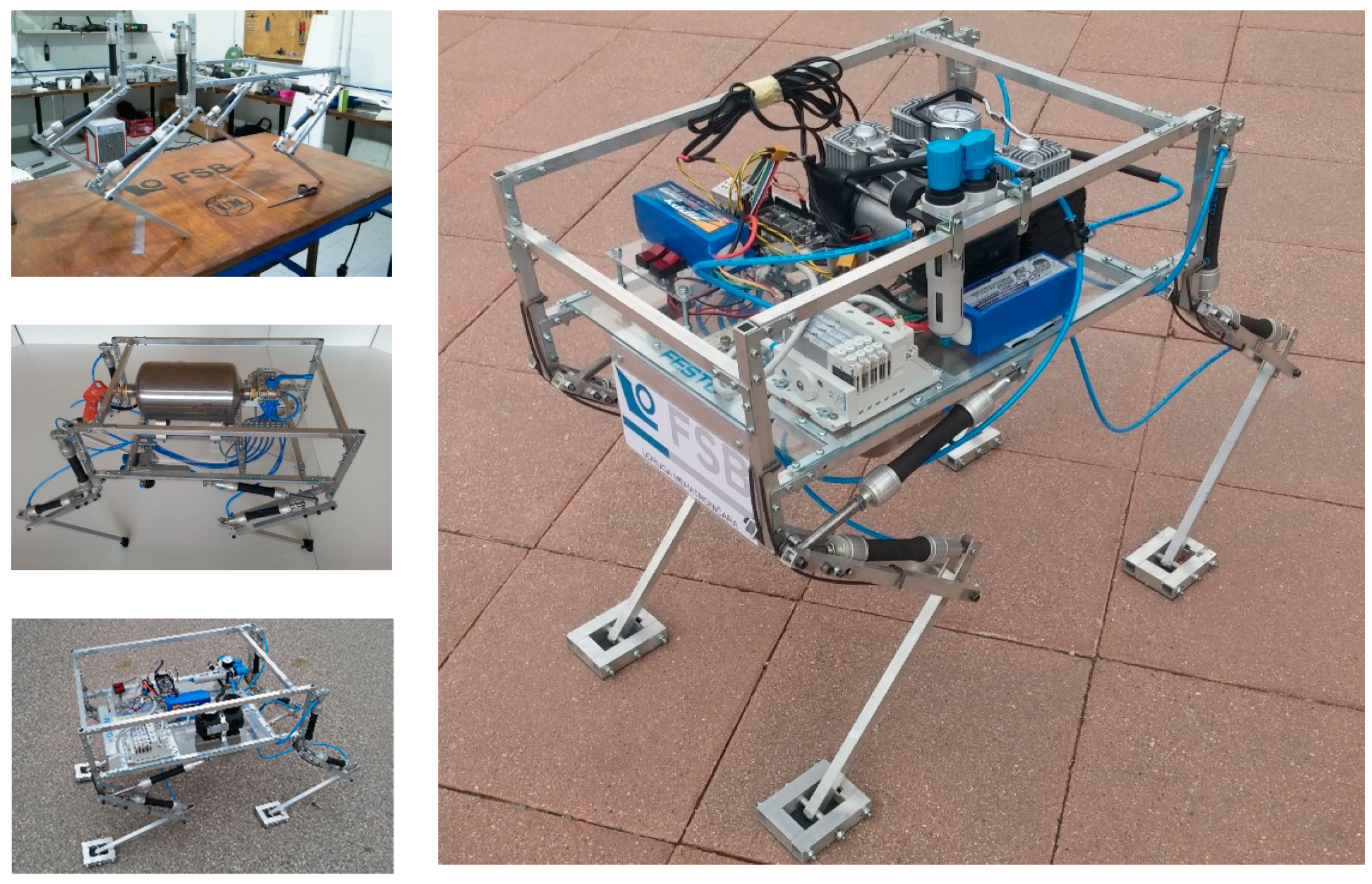
In response to the increasing interest in mobile robotics, we launched a project to develop WRAPAM (Walking Robot Actuated by Pneumatic Artificial Muscles), drawing inspiration from horses or dogs, for a four-legged walking robot. The robot incorporates four key components: an energy system for compressed air, actuators for joint movement, a control system for processing information, and sensors for environmental monitoring. This custom-designed quadruped robot offers two degrees of freedom per leg, powered by eight Festo air muscles (type DMSP-20-150N-AM-CM). A modular valve terminal system with eight solenoid coils controls the movement. Each leg incorporates two movable rotational segments and a torsional spring to enhance joint agility. The robot contains a compact electronics module housing an Arduino Mega (AT-mega2560 microcontroller) for movement control. This microcontroller was chosen due to its accessibility, cost-effectiveness, and numerous I/O ports for future upgrades. An integrated ULN2803A chip amplifies signals from the microcontroller to the pneumatic valves. A Bluetooth module allows wireless communication between the robot and its operator. All components of the compressed air supply system and control unit are carefully mounted on the hand-crafted aluminum frame to achieve the robot's balance. The pneumatically actuated quadruped robot, shown in
Figure 1, operates fully autonomously and offers Bluetooth and USB connectivity for computer interaction.
2.1.2. Manipulator Arm Actuated by PAMs
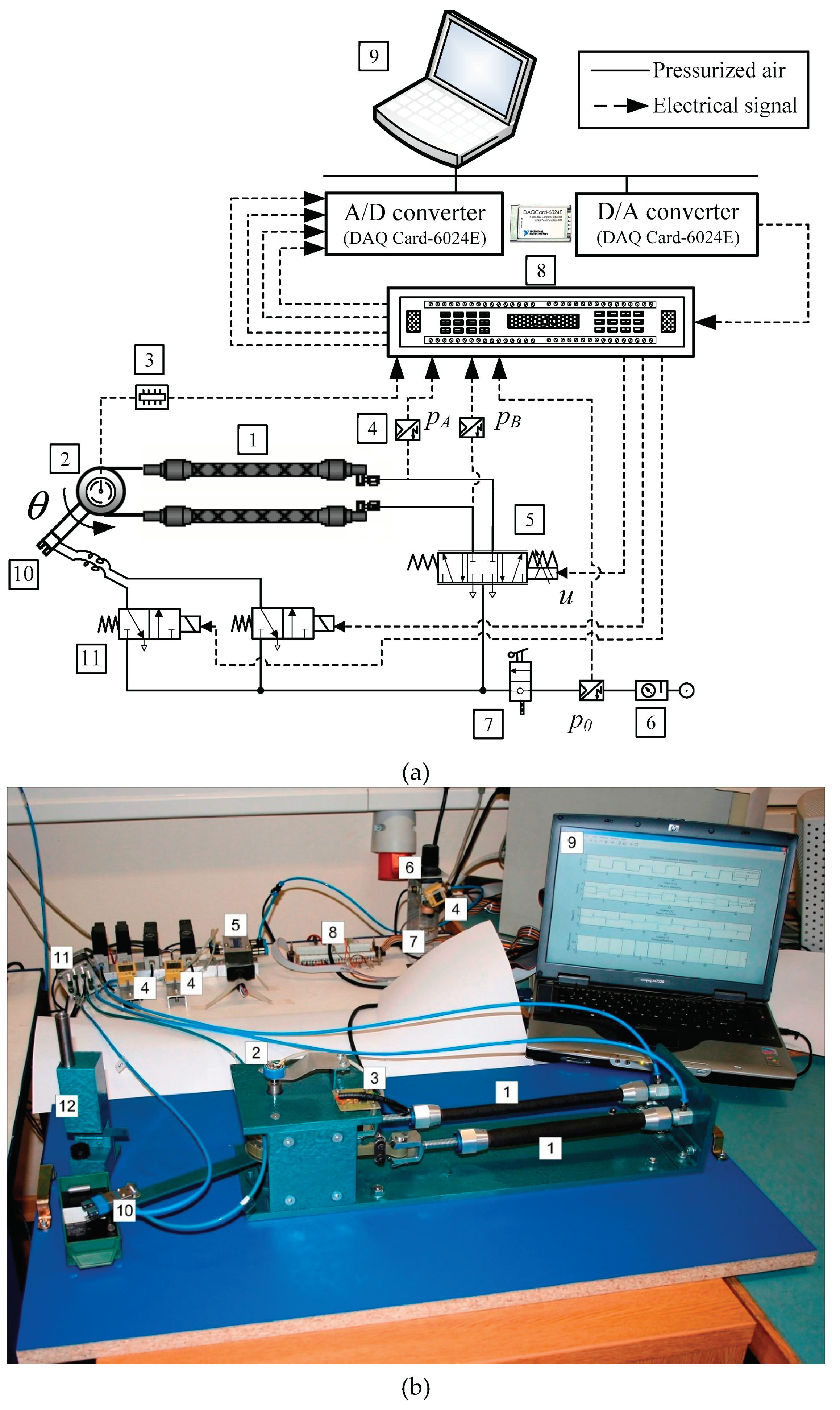
Fluidic muscles have significant potential for industrial applications, particularly in assembly automation. Their compact size, high strength-to-weight ratio, inherent safety, and simplicity make them attractive options for advanced robotic manipulation systems. The antagonistic configuration of the PAM actuators imitates a biceps-triceps system, emphasizing the similarity between these artificial muscles and human skeletal muscles. Compressed air-powered artificial muscle actuators contract lengthwise upon radial expansion, converting radial force into axial contraction. Muscle actuators typically achieve a maximum contraction of 25% of their nominal length. Bidirectional movement requires antagonistic coupling. Two PAMs replicate the human elbow, functioning as antagonistic pairs (like biceps and triceps) to rotate a joint. As pressure increases in one PAM, it decreases in the other, resulting in torque generation like muscle contraction. A control signal sent to the valve defines muscle pressure, causing antagonistic contractions that rotate the manipulator arm.
Figure 2.
Manipulator arm actuated by PAMs, (a) schematic diagram, (b) photo. Legend: 1: Pneumatic muscles; 2: Rotary potentiometer; 3: Voltage reference card; 4: Pressure sensors; 5: Proportional control valve; 6: Filter-regulator unit; 7: Manually operated valve; 8: Electronic interface; 9: Control computer with DAC card; 10: Gripper; 11: High-speed on/off solenoid valve; 12: Feeder.
The experimental system consists of two key parts: a pneumatic system and a control system. The pneumatic system utilizes an air supply unit (SMC EAW 2000-F01), a proportional directional control valve (Festo MPYE-5 1/8 HF-010B), and two opposing muscles to generate joint movement (Festo MAS-10-220N-AA-MC-K). Antagonistic muscles provide power for the rotation of the joint. Pressure transducers (SMC ISE4-01-26) monitor internal muscle pressure and the overall supply. Torque is created from the pressure difference within the opposing muscles, turning a lever with a pneumatic gripper (Festo HGP-06-A). A single-turn potentiometer measures the joint angle (
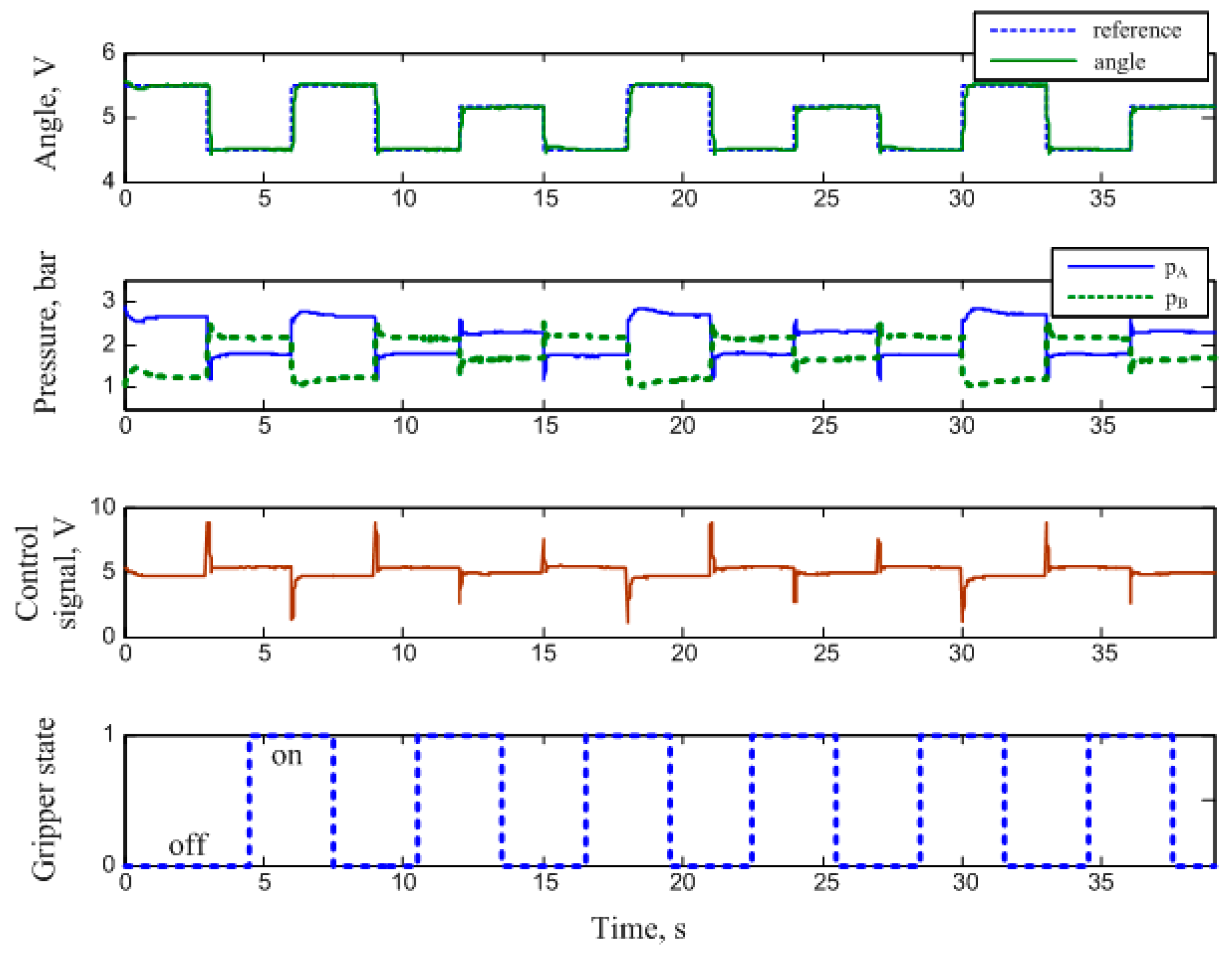
θ) and sends this information back to the control system. The control computer, equipped with a data acquisition card (NI DAQCard 6024E for PCMCIA with 12-bit A/D and 12-bit D/A converter), processes the signals. This procedure enables the manipulation arm to rotate using a pneumatic drive within a closed loop system. The control system calculates the value of the control signals sent to the valve, adjusting the airflow and the arm's movement. Sensors monitor the arm's position, and a high-speed valve activates the gripper in the required position. One example of manipulator arm motion during the transfer of roller workpieces from the feeder to the box is shown in
Figure 3 [
19].
2.2. Autonomous Vehicles
2.2.1. Autonomous Vehicles Driven by PAMs
Electronic devices enable modern control techniques for pneumatic drives, broadening their application in robotics and mobile systems. Creating autonomous mobile robots for unstructured environments presents a complex engineering challenge, requiring advanced navigation, control, and alternative propulsion systems. Although electrification is often favored for environmental benefits, innovative solutions such as fluidic muscles offer exciting possibilities for future mobile systems. The prototype of an autonomous vehicle powered by PAMs is shown in
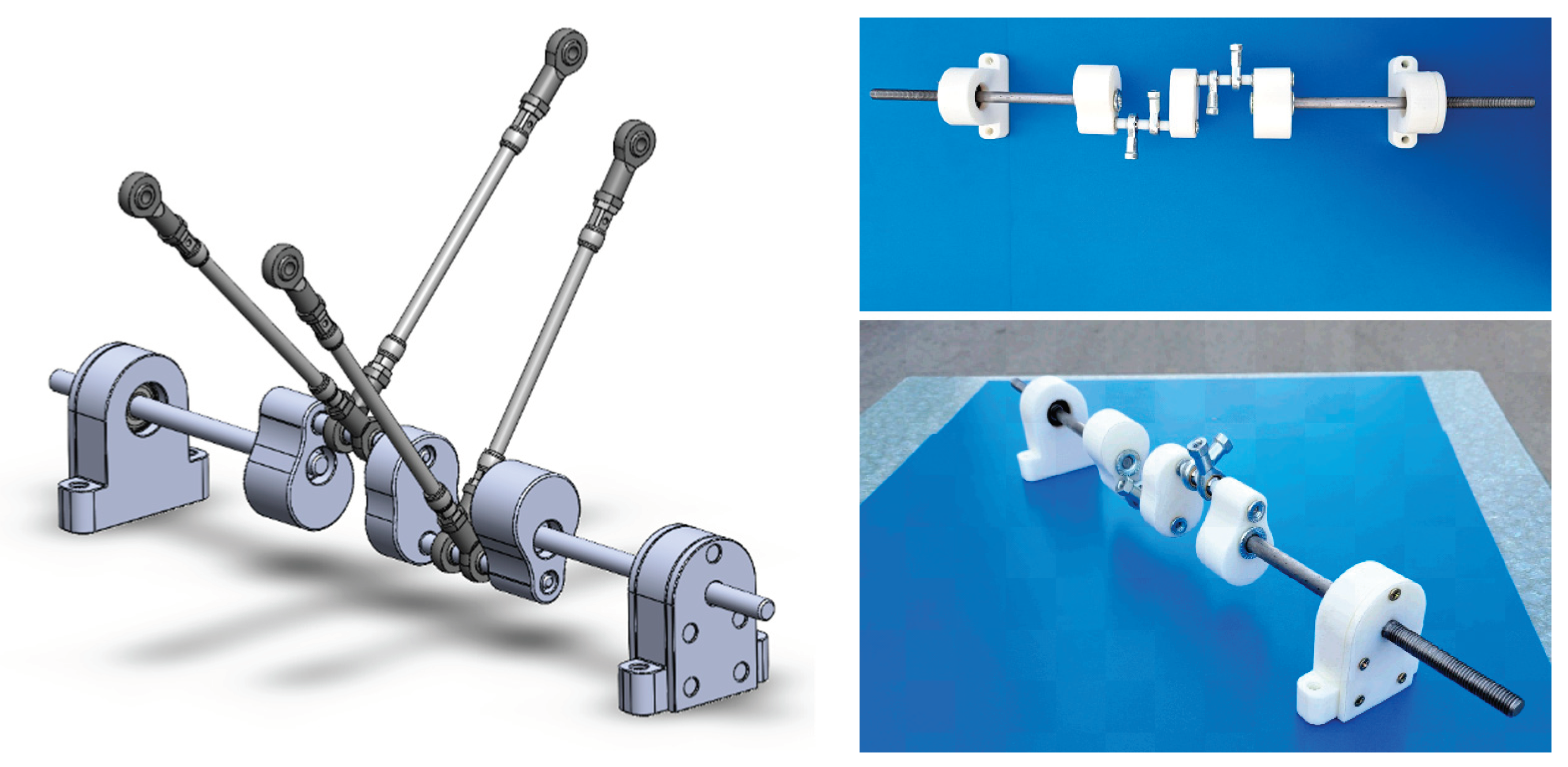
Figure 4. The autonomous vehicle utilizes a crankshaft mechanism to convert the pulling force of three pneumatic muscles into continuous rotation for the wheels. Each crankshaft segment rotates 120° relative to the previous one, achieving a full revolution. Four bearings support the crankshaft due to unbalanced bending load during operation. Stainless steel, machined through turning and milling, is employed for vehicle construction [
20].
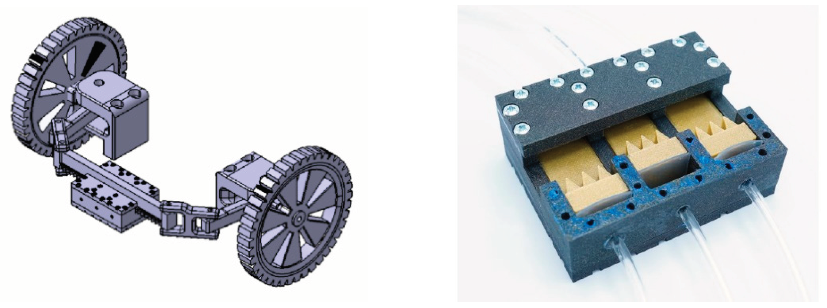
The chassis construction prioritized strength and simplicity, utilizing an L-profile as the primary structural component and integrating the necessary fixings for areas subjected to dynamic stress. The dimensions of the chassis are 1100x360 mm, and it is made by welding. Additionally, the vehicle mechanics, including the drive shaft and steering system, were studiously designed. Steering is achieved using a pneumatic linear stepper motor controlled by a microcontroller, employing rack and pinion geometry to enable differential rotation of inner and outer wheels,
Figure 5. The pneumatic linear stepper motor is made on a 3D printer, so it has a metal-free design and uses a toothed rack driven by three phased pistons, enabling 1/3-step increments for wheel rotation.
The vehicle uses two sources of electricity. The first source, used to operate the compressor, provides 12V with a maximum current of 300A. The second source supplies the valve block, utilizing a rechargeable battery with a capacity of 3000 mAh and a rated voltage of 22.2 V. The control device uses an Arduino microcontroller for vehicle control and autonomous driving functions. Airflow into the drive system is controlled by MOSFET transistors. LED indicators display power status. The compressed air from the compressor is stored in the tank, and when the pressure in the tank drops below 5 bar, the pressure switch is activated. The microcontroller activates the electromagnetic valves supplying the pneumatic muscles with compressed air.
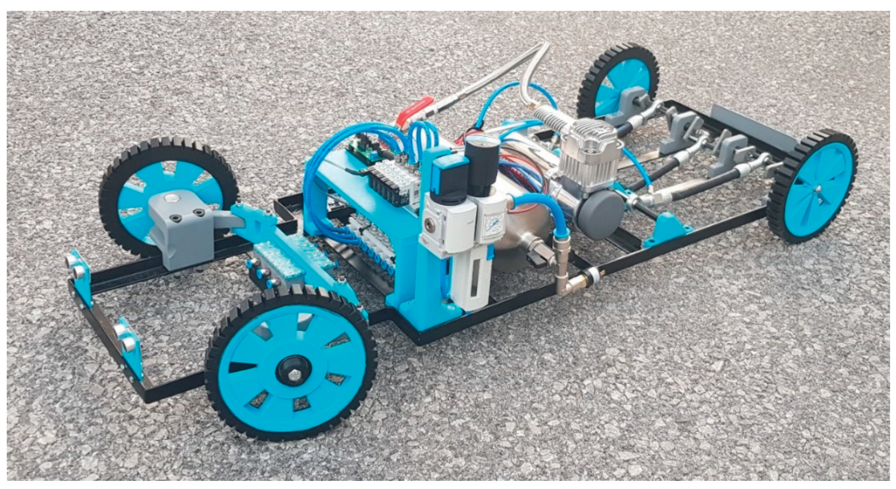
This section also describes another model of autonomous vehicle powered by PAMs. This vehicle uses a crankshaft drive system with four PAMs positioned in a V-shape. Initially designed with three actuators, the drive system was unable to complete a full circle of the crankshaft due to insufficient muscle contraction. To solve this issue, an additional actuator was added. Two muscles are positioned on each side, with a 180° difference in mounting location on the crankshaft to align with the spacing between the eccentrics of the first and second hinges. This crankshaft design is similar to those found in traditional motorcycle applications. The pneumatic muscles are placed at an angle of 45° from the vertical (radial) axis of the shaft, as shown in
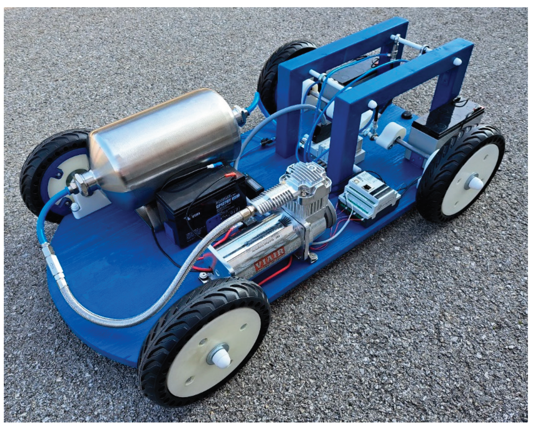
Figure 6. Pneumatic muscles are arranged in a 1-4-3-2 sequence perpendicular to the axis of the shaft. Their 180° offset allows sequential activation with each 90° shaft rotation, ensuring continuous rotation. The complete vehicle with the pneumatic muscle engine is shown in
Figure 7.
2.3. Mechatronic Systems
2.3.1. Ball on Beam Balancing Mechanism Actuated by PAMs
The complex ball and beam system is a popular benchmark for advanced control methods due to its challenges in design and application. Like inverted pendulums or inverted wedge systems, it showcases various non-linear control techniques including feedback stabilisation, variable structure control, passivity-based control, back-stepping and forwarding, nonlinear observers, friction compensation and many others [
21,
22,
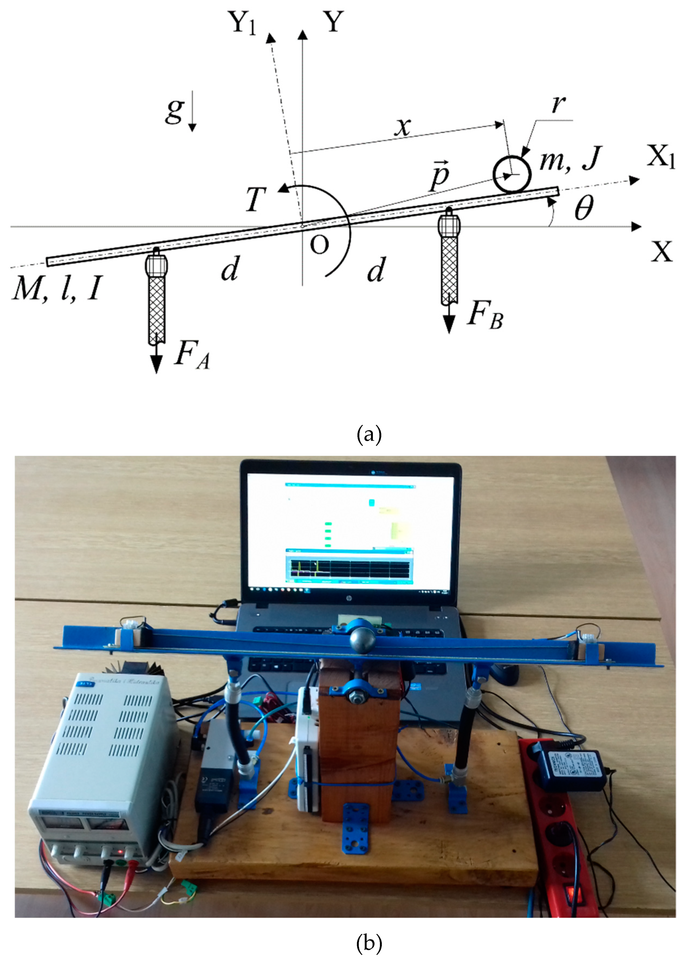
23]. The ball and beam system provides a model for solving the stabilization challenges of inherently unstable systems in control engineering. In this unique system, PAMs are used to rotate the beam while balancing the system, but their air compressibility and non-linear force/contraction characteristics add further complexity to the control task. The experimental setup consists of two parts: a mechanical section with the ball-and-beam mechanism, pneumatic valves, and sensors, and a control section with the computer and data acquisition system.
Figure 8 shows the ball-and-beam mechanism actuated by PAM actuators.
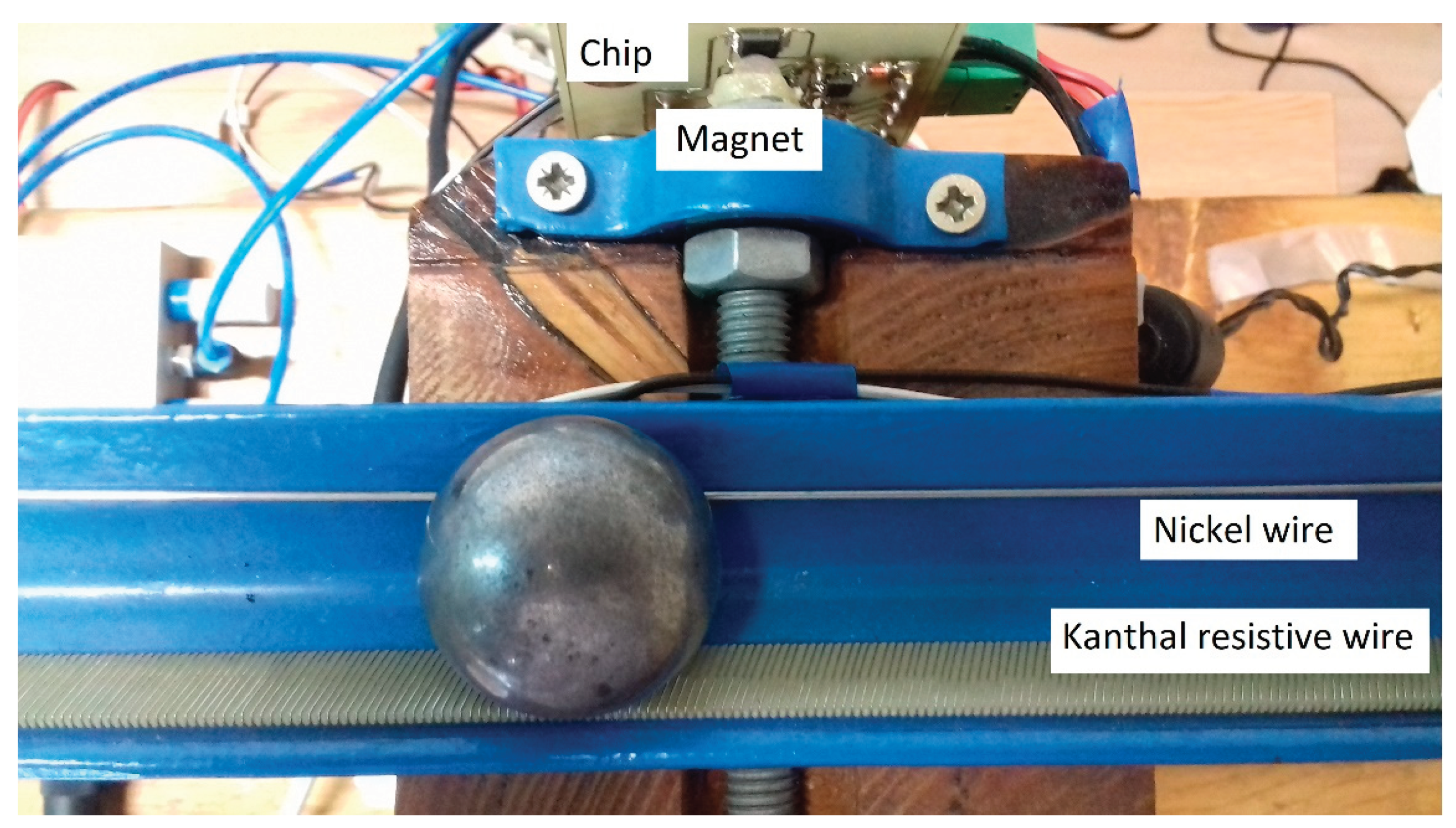
Using antagonistic pneumatic muscles (Festo DMSP-10-150N-RM-CM) to act on a revolute joint, a V-shaped steel beam rotates vertically while being mounted on bearings on a wooden support. The pressure difference between the muscles controls the rotation. A proportional control valve regulates pressurized gas flow to the pneumatic muscles. The valve's control signal operates within a voltage range of 0 to 10 V. When the voltage is 5V, the valve is closed, and no air flows inflating the PAMs, resulting in zero pulling force. The ball's stabilization is achieved through a digital controller implemented on the control computer. Signals measured from the process are sent back to the control computer via a data acquisition card (NI USB-6212), equipped with a 16-bit analog-to-digital and digital-to-analog converter. The control software is developed in the Matlab/Simulink environment and converted into ANSI C code using the Real-Time Workshop (RTW) program. The ball position measuring system utilizes a sliding potentiometer design, employing a metal ball to act as the slider component. The "sliding resistor" consists of kanthal resistive wire (ferritic iron-chromium-aluminium alloy) wound around a vitroplast board. When the beam angle changes, gravity causes the ball to roll freely along the beam. As the ball rolls, it contacts the resistive wires, effectively closing the electrical circuit. The beam angle is measured using a 12-bit contactless magnetic rotary position sensor (AMS AS5045). This sensor integrates Hall elements, analogue front end, and digital signal processing into a single device, forming a system-on-chip. To measure the angle, a neodymium magnet is positioned on the beam shaft directly above the magnetic encoder.
Figure 9 illustrates both the ball position and the beam angle measuring system [
24].
2.3.2. Ball on Plate Balancing Mechanism Actuated by PAMs
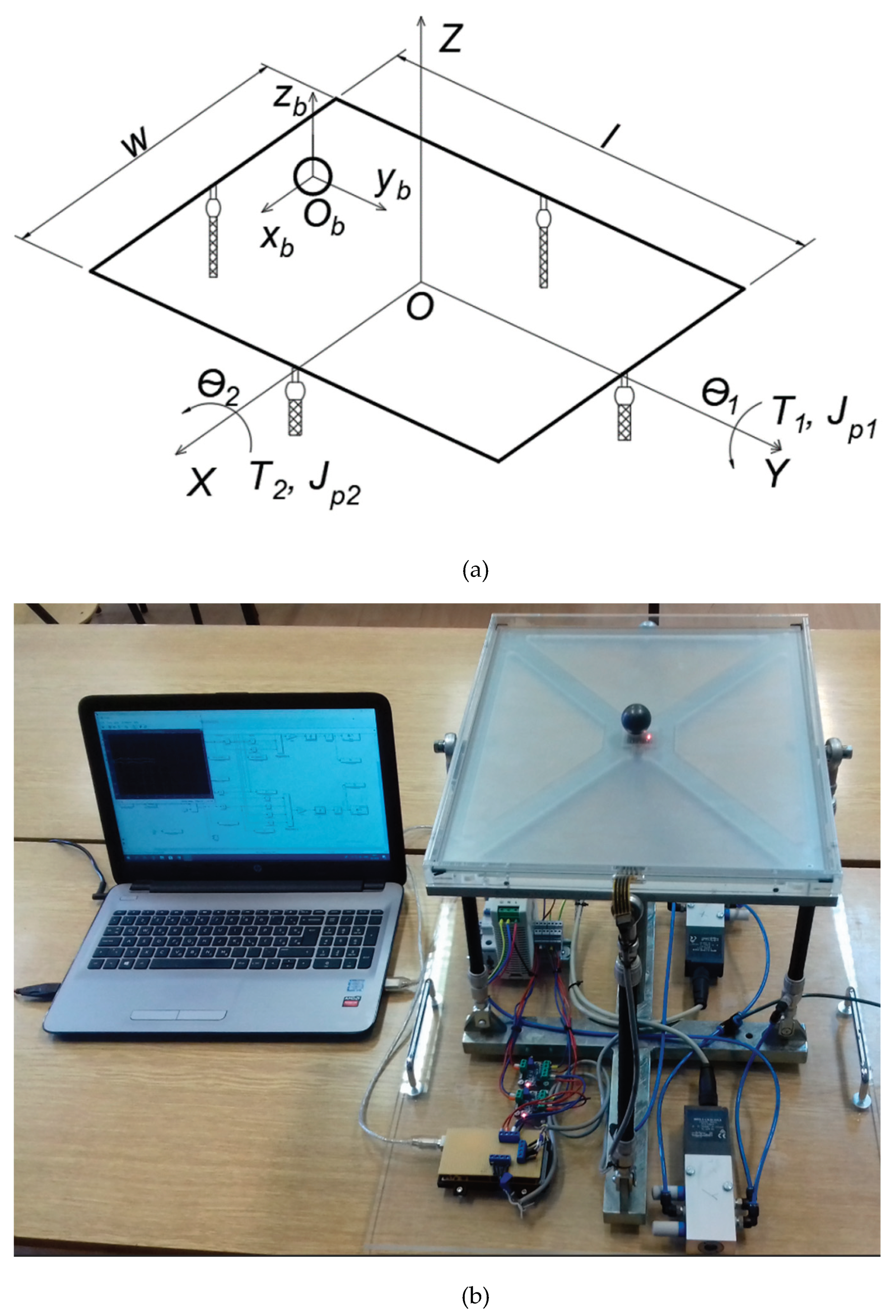
The ball and plate system expands the two-degree-of-freedom ball and beam system to four degrees of freedom. It's a benchmark problem in control theory known for its nonlinear, multivariable, under-actuated, and unstable open-loop dynamics. The control task involves both point stabilization and trajectory tracking. The balancing platform, depicted in
Figure 10, is used to explore advanced control techniques in the field of pneumatic systems. In the experimental setup, a steel ball is positioned on a 17-inch resistive touchscreen equipped with four-wire analog input capabilities. The ball's position is determined by measuring voltage drops ranging from 0 to 5 volts along both the X and Y axes, facilitated by an Arduino Mega 2560 microcontroller. The primary limitation of the resistive touchscreen is the simultaneous measurement of both coordinates. To overcome this, each position is measured separately with a 1 microsecond delay, ensuring enough time for voltage stabilization along the second axis. The touchscreen is mounted on a transparent plexiglass plate, fastened to an aluminum frame. Angular velocity is measured using the MPU 6050 accelerometer/gyroscope chip, which is positioned centrally within the aluminum frame. This chip combines a three-axis gyroscope and accelerometer into a single unit, providing four programmable scale ranges for measuring angular velocity in degrees per second. Additionally, it contains a built-in digital programmable low-pass filter. For communication with the microcontroller, the gyroscope uses the I2C communication protocol. Two pairs of Festo PAMs (DMSP-10-200N-RM-CM) are arranged antagonistically to rotate the plate around the spherical joint. The torque required for plate rotation along both the X and Y axes is achieved through muscle contraction. To control the muscle contraction, two proportional 5/3 control valves (Festo MPYE-5 1/8 HF-010B) are used.
Each valve receives a control signal ranging from 0 to 10 volts, adjusting the flow rate and consequently creating a pressure differential in the PAMs, leading to their contraction. To control the proportional valves, an Arduino microcontroller is employed, producing a PWM signal ranging from 0 to 5 VDC. Consequently, two voltage converters were required to achieve the desired range of 0 to 10 V. Initially, the Arduino's PWM signal is set to 2.5 V, which after conversion results in 5 V, positioning the valve spool in the middle position and ensuring uniform flows to the PAMs. The controller is developed within the Matlab/Simulink environment on a PC. It employs custom-built blocks for the touchscreen functionality, an additional library for the sensor module, and the Simulink support package for Arduino integration. The controller's efficiency is evaluated through three test scenarios: stabilizing the ball in the center of the plate and tracking circular and square trajectories.
2.4. Orthopaedic Devices
Pneumatic muscles are often used in musculoskeletal rehabilitation for elderly or injured persons, functioning as actuators in powered orthoses. Ankle-foot orthoses are generally classified as passive or active. Passive foot orthoses use spring mechanisms made from various materials to aid the patient's gait. On the other hand, active orthoses use powered mechanisms to generate the force needed to lift the foot into the correct position for regular walking. [
25,
26,
27]. Below is a description of a prototype of an active ankle-foot orthosis developed in our lab.
2.4.1. Active Ankle-Foot Orthotic Device Actuated by PAM
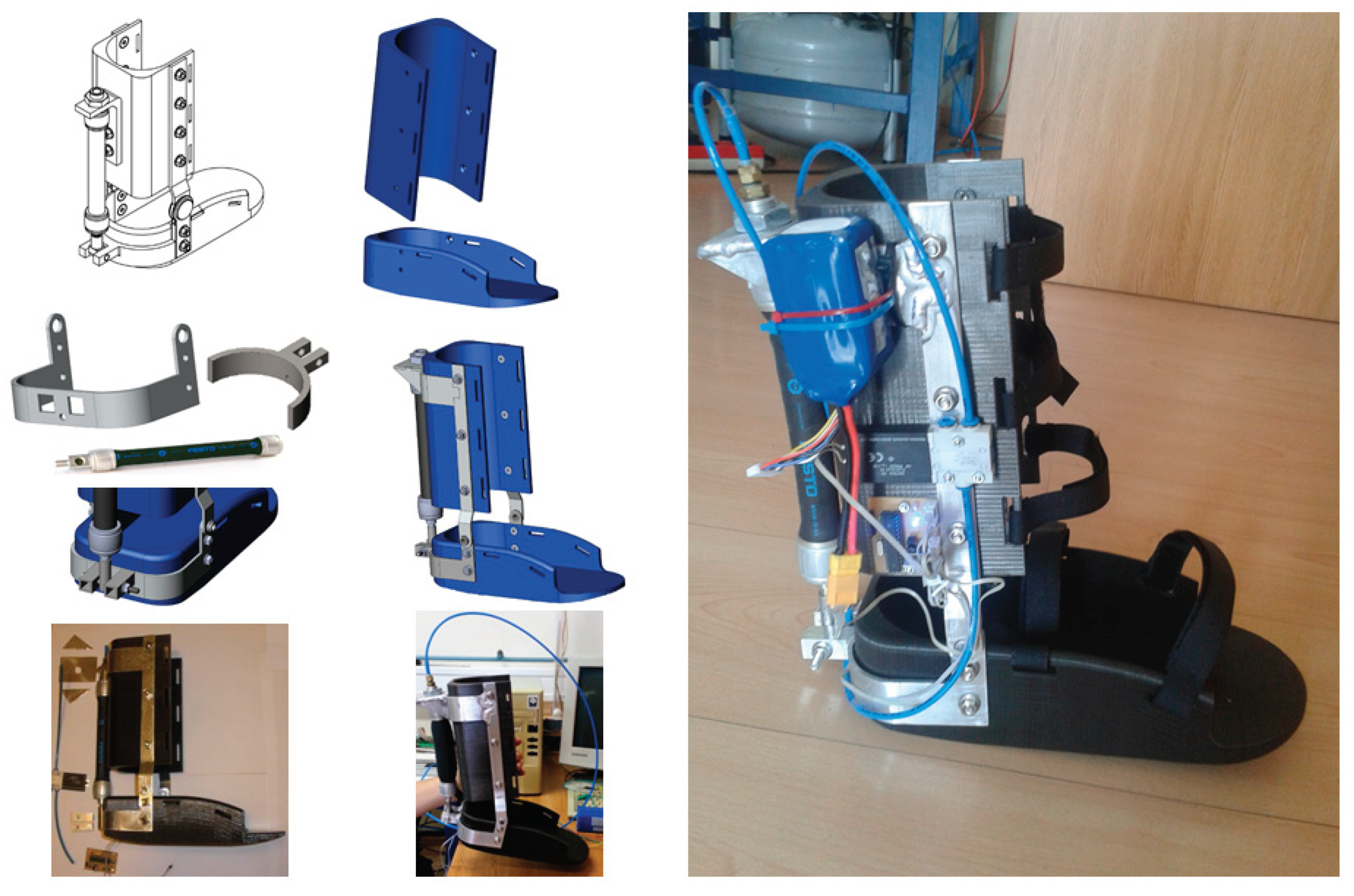
Figure 11 illustrates the active ankle-foot orthosis powered by pneumatic technology, designed to assist individuals with foot drop, who have difficulty raising their feet independently while walking. This device helps in returning the patient's foot to its natural position, thus improving the ability to walk. The orthosis utilizes an air muscle (Festo DMSP-20-150N-AM-CM) powered by a solenoid valve (Festo MHE2-MS1H-3/2G-QS-4-K). Initially, a 3D prototype was created using SolidWorks, followed by the fabrication of the orthosis using PLA plastic with a 3D printer to minimize weight. To further enhance its lightweight design, hollow interiors were incorporated into the plastic components. The connecting elements are made from aluminum. The orthosis is specifically designed to be securely worn on the lower leg of the patient, fastened in place using strap belts. The control system employs the ATmega328 microcontroller. Two switches are integrated underneath the orthosis, positioned beneath the heel and toes. When the first micro-switch beneath the heel sends a signal, the microcontroller starts a timer. It then waits for a signal from the second micro-switch located under the toes. Once this signal is received, the microcontroller stops the timer and activates the valve after a time interval equivalent to the duration between receiving signals from both micro-switches. This method empowers the patient to regulate their walking speed, leading to enhanced stability and expediting the adaptation process to the orthosis. To activate the solenoid valve, a 24V signal voltage is necessary. The voltage regulator was developed using the ULN2803A Darlington driver. This setup enables the control of pressure within the muscle, which achieves the contraction force required to lift the foot into position for a new leg movement. To ensure portability, the system requires an external compressed gas source, which the user carries on their back.
3. Results
The rapid spread of digital technologies, including concepts such as the Internet of Things, visual systems, 5G networks, and Artificial Intelligence, has sparked significant interest in scientific research and practical applications across various fields, including pneumatic driving systems. This raises the question of whether "traditional" techniques like pneumatic systems can remain relevant in the future digital era, meeting the evolving demands of digital technologies and energy efficiency [
28,
29]. Creating high-performance systems driven by fluidic muscles for modern industrial plants, mobile systems, mechatronic and robotic systems require the integration of mechanical systems with technologies such as microelectronics, sensors, and advanced control methods to optimize system behavior. While pneumatic drives can offer a cost-effective alternative to electric and hydraulic systems, particularly for smaller loads, there remains a need for further research into advanced control techniques for these systems. By incorporating electronic components for signal transmission and processing, advanced control methods can be developed for PAM-driven systems, enabling their integration into automated technical systems based on modern digital technology principles. This expands the potential applications of pneumatic systems towards flexible modules in complex production systems, bio-robotic mechanisms, transportation systems, and others.
In these efforts, the article explained several systems powered by PAMs, demonstrating development trends that can serve as educational models for studying advanced control techniques.
4. Discussion
Educators across the globe acknowledge the importance of the interaction of classical and modern control theory with practical applications and comparative analysis of various control techniques [
30]. Implementing controller design processes in real physical systems enriches the understanding of automatic control theory. Feedback from students underscores the advantages of laboratory-oriented teaching methodologies, which include a practical demonstration of control systems, activities with different electric and pneumatic components, understanding mathematical models of systems, and recognizing the discrepancies between real-world system operations and theoretical models which are commonly used in simulations.
5. Conclusions
The article presented several handmade experimental systems powered by PAMs, serving as instructional models for pneumatic systems and feedback control education for mechanical engineering students. PAMs can be used as highly suitable actuators for innovative industrial and walking robots, mechatronic systems, and devices simulating human functions. By demonstrating unique and intuitively clear operating principles through pneumatically actuated experimental models, students gain insights into mechanical system construction, mathematical descriptions of practical systems, parameter identification of real processes, simulation of nonlinear and linearized models, exploration of various control techniques, and experimental validation of results. This approach generally results in a deeper understanding of fluid power systems and automatic control theory as widely applicable engineering disciplines.
Supplementary Materials
The following supporting information can be downloaded at the website of this paper posted on Preprints.org. Video S1: Walking robot actuated by PAMs; Video S2: Manipulator driven by PAMs; Video S3: Autonomous vehicle driven by PAMs; Video S4: Ball on beam system actuated by PAMs; Video S5: Ball on plate system actuated by PAMs; Video S6: Active ankle foot orthosis actuated by PAM.
Author Contributions
Conceptualization, Ž.Š. and J.B.; methodology, Ž.Š., M.C. and J.B.; software, Ž.Š. and J.B.; validation, Ž.Š. and J.B.; formal analysis, Ž.Š. and M.C.; investigation, Ž.Š., M.C. and J.B.; resources, Ž.Š.; data curation, J.B.; writing—original draft preparation, Ž.Š. and J.B.; writing—review and editing, Ž.Š. and M.C.; supervision, Ž.Š. and M.C.; project administration, J.B.; funding acquisition, Ž.Š. All authors have read and agreed to the published version of the manuscript.
Funding
This research was funded by the University of Zagreb, through tenders for short-term financial support for research in the period 2018-2023.
Data Availability Statement
Not applicable.
Acknowledgments
We thank the companies Festo Croatia and SMC Croatia for the cooperation and sponsorship of pneumatic equipment necessary for the realization of experimental systems. We are most grateful to the students of the Faculty of Mechanical Engineering and Naval Architecture (Dominik Sremić, Hrvoje Brezak, Valentino Štahan, Vedran Tatalović, Viktor Mandić, Srečko Herceg, Šime Grbić, Filip Čavić, Petar Trslić, Tomislav Hodja, Marin Miletić, Hrvoje Selak, Andreas Šantek and Denis Trivić) who participated in the creation of experimental systems during their graduation theses.
Conflicts of Interest
The funders had no role in the design of the study; in the collection, analyses, or interpretation of data; in the writing of the manuscript; or in the decision to publish the results.
References
- Kalita, B.; Leonessa, A.; Dwivedy, S.K. A Review on the Development of Pneumatic Artificial Muscle Actuators: Force Model and Application. Actuators 2022, 11, 288. [Google Scholar] [CrossRef]
- Daerden, F.; Lefeber, D. Pneumatic Artificial Muscles: actuators for robotics and automation. European Journal of Mechanical and Environmental Engineering. 2002, 47, 11–21. [Google Scholar]
- Jamil, B.; Oh, N.; Lee, J.G.; et al. A Review and Comparison of Linear Pneumatic Artificial Muscles. Int. J. of Precis. Eng. and Manuf.-Green Tech. 2024, 11, 277–289. [Google Scholar] [CrossRef]
- Palko, A.; Smrček, J. The use of pneumatic artificial muscles in robot construction. Industrial Robot 2011, 38, 11–19. [Google Scholar] [CrossRef]
- Caldwell, D.G.; Tsagarakis, N.; Medrano-Cerda, G.A. Bio-mimetic actuators: polymeric pseudo muscular actuators and pneumatic muscle actuators for biological emulation. Mechatronics 2000, 10, 499–530. [Google Scholar] [CrossRef]
- Rahman, R.A; Sepehri, N. Design and experimental evaluation of a dynamical adaptive backstepping-sliding mode control scheme for positioning of an antagonistically paired pneumatic artificial muscles driven actuating system. International Journal of Control 2017, 90, 249–274. [Google Scholar] [CrossRef]
- Sárosi, J.; Bíró, I.; Nemeth, J.; Cveticanin, L. Dynamic modeling of a pneumatic muscle actuator with two-direction motion. Mechanism and Machine Theory 2015, 85, 25–34. [Google Scholar] [CrossRef]
- Lilly, J.H. Adaptive Tracking for Pneumatic Muscle Actuators in Bicep and Tricep Configurations. IEEE Trans. on Neural Systems and Rehabilitation Engineering 2003, 11, 333–339. [Google Scholar] [CrossRef]
- Ahn, K.K.; Nguyen, H.T.C. Intelligent switching control of a pneumatic muscle robot arm using learning vector quantization neural network. Mechatronics 2007, 17, 255–262. [Google Scholar] [CrossRef]
- Chang, M.-K.; Yen, P.-L.; Yuan, T.-H. Angle Control of a one-Dimension Pneumatic Muscle Arm using Self-Organizing Fuzzy Control. In Proceedings of the IEEE Int. Conf. on Systems, Man, and Cybernetics, Taipei, Taiwan, 8–11 October 2006. [Google Scholar]
- Xie, S.; Mei, J.; Liu, H.; Wang, Y. Hysteresis modeling and trajectory tracking control of the pneumatic muscle actuator using modified Prandtl–Ishlinskii model. Mech. Mach. Theory 2018, 120, 213–224. [Google Scholar] [CrossRef]
- Mhd Yusoff, M.A.; Mohd Faudzi, A.A.; Hassan Basri, M.S.; Rahmat, M.F.; Shapiai, M.I.; Mohamaddan, S. Switching Model Predictive Control for Thin McKibben Muscle Servo Actuator. Actuators 2022, 11, 233. [Google Scholar] [CrossRef]
- Hosoda, K.; Sakaguchi, Y.; Takayama, H.; Takuma, T. Pneumatic-driven jumping robot with anthropomorphic muscular skeleton structure. Autonomous Robots 2010, 28, 307–316. [Google Scholar] [CrossRef]
- Verrelst, B.; Vermeulen, J.; Van Ham, R.; Lefeber, D. Control Architecture for the Pneumatically Actuated Dynamic Walking Biped 'Lucy'. Mechatronics 2005, 15, 703–729. [Google Scholar] [CrossRef]
- Aschenbeck, K.S.; Kern, N.I.; Bachmann, R.J.; Quinn, R.D. Design of a Quadruped Robot Driven by Air Muscles. In Proceedings of the First IEEE/RAS-EMBS Int. Conf. on Biomedical Robotics and Biomechatronics; 2006; pp. 875–880. [Google Scholar]
- Espenschied, K.S.; Quinn, R.D.; Beer, R.D.; Chiel, H.J. Biologically based distributed control and local reflexes improve rough terrain locomotion in a hexapod robot. Robotics and Autonomous Systems 1996, 18, 59–64. [Google Scholar] [CrossRef]
- Chen, X.; Wang, L.Q.; Ye, X.F; Wang, G.; Wang, H.L. Prototype development and gait planning of biologically inspired multi-legged crablike robot. Mechatronics 2013, 23, 429–444. [Google Scholar] [CrossRef]
- Shao, Q.; et al. Untethered Robotic Millipede Driven by Low-Pressure Microfluidic Actuators for Multi-Terrain Exploration. IEEE Robotics and Automation Letters 2022, 7, 12142–12149. [Google Scholar] [CrossRef]
- Šitum, Ž.; Herceg, S.; Bolf, N.; Ujević Andrijić, Ž. Design, Construction and Control of a Manipulator Driven by Pneumatic Artificial Muscles. Sensors 2023, 23, 776. [Google Scholar] [CrossRef]
- Šitum, Ž.; Benić, J.; Grbić, Š.; Vlahović, F.; Jelenić, D.; Kosor, T. Mechatronic systems with pneumatic drive, In Proceedings of the Int. Conf. Fluid Power 2019, Maribor, Slovenia, 19-20 September 2019. [Google Scholar]
- Almutairi, N. B.; Zribi, M. On the sliding mode control of a ball on a beam system. Nonlinear Dynamics 2010, 59, 221–238. [Google Scholar] [CrossRef]
- Keshmiri, M.; Jahromi, A. F.; Mohebbi, A.; Amoozgar, M. H.; Xie, W. F. Modeling and control of ball and beam system using model based and non-model based control approaches. Int. J. Smart Sens. Intell. Syst. 2012, 5, 14–35. [Google Scholar] [CrossRef]
- Chang, Y. H.; Chan, W. S.; Chang, C. W. TS fuzzy model-based adaptive dynamic surface control for ball and beam system. IEEE Trans. Ind. Electron. 2013, 60, 2251–2263. [Google Scholar] [CrossRef]
- Šitum, Ž.; Trslić, P. Ball and Beam Balancing Mechanism Actuated With Pneumatic Artificial Muscles. ASME. J. Mechanisms Robotics. 2018, 10, 055001. [Google Scholar] [CrossRef]
- Alam, M.; Choudhury, I.A.; Mamat, A.B. Mechanism and Design Analysis of Articulated Ankle Foot Orthoses for Drop-Foot. The Scientific World Journal 2014. [Google Scholar] [CrossRef]
- Gordon, K.E.; Sawicki, G.S.; Ferris, D.P. Mechanical performance of artificial pneumatic muscles to power an ankle–foot orthosis. Journal of Biomechanics 2006, 39, 1832–1841. [Google Scholar] [CrossRef]
- Shorter, K. A.; Xia, J.; Hsiao-Wecksler, E. T.; Durfee, W. K.; Kogler, G. F. Technologies for Powered Ankle-Foot Orthotic Systems: Possibilities and Challenges. IEEE/ASME Trans on Mechatronics 2013, 18, 337–347. [Google Scholar] [CrossRef]
- Scheidl, R.; Linjama, M.; Schmidt, S. Discussion: Is the future of fluid power digital? Proc. Inst. Mech. Eng., Part I: Journal of Systems and Control Engineering 2012, 226, 721–723. [Google Scholar] [CrossRef]
- Alt, R.; Malzahn, J.; Murrenhoff, H.; Schmitz, K. A Survey of Industrial Internet of Things in the Field of Fluid Power: Basic Concept and Requirements for Plug-and-Produce. In Fluid Power Systems Technolog 2018, 51968, V001T01A015. [Google Scholar] [CrossRef]
- Cox, D. J. Hands-on experiments in dynamic systems and control for applied education in robotics and automation. In Proceedings of the World Automation Congress, Waikoloa, HI, USA; 2008; pp. 1–6. [Google Scholar]
|
Disclaimer/Publisher’s Note: The statements, opinions and data contained in all publications are solely those of the individual author(s) and contributor(s) and not of MDPI and/or the editor(s). MDPI and/or the editor(s) disclaim responsibility for any injury to people or property resulting from any ideas, methods, instructions or products referred to in the content. |
© 2024 by the authors. Licensee MDPI, Basel, Switzerland. This article is an open access article distributed under the terms and conditions of the Creative Commons Attribution (CC BY) license (http://creativecommons.org/licenses/by/4.0/).
