1. Introduction
Leaf springs are constituted by several structural and assembly elements, which can be employed by different mounting methods, depending on the application sector of the leaf springs. These elements have an important role in providing structural stability to the component. Examples of connection elements are spring buckles, clamps, or threaded rods [
1,
2,
3,
4,
5]. Assembling leaf springs by threading are most often found in road freight vehicles, light and heavy vehicles [
1,
2,
3,
5,
6]. This assembling method requires that during the manufacturing process of the leaves, a through hole is produced. The production of this hole for mounting has brought problems in terms of fatigue fracture in this type of leaves [
7,
8,
9,
10,
11]. Additionally, the usage of retaining clamps applied on the ends of leaf springs is often found in the road industry.
On the other hand, leaf springs connected with a spring buckle are usually found in the railway sector [
12,
13,
14,
15,
16]. For leaf springs standardised by the International Union of Railways (UIC) [
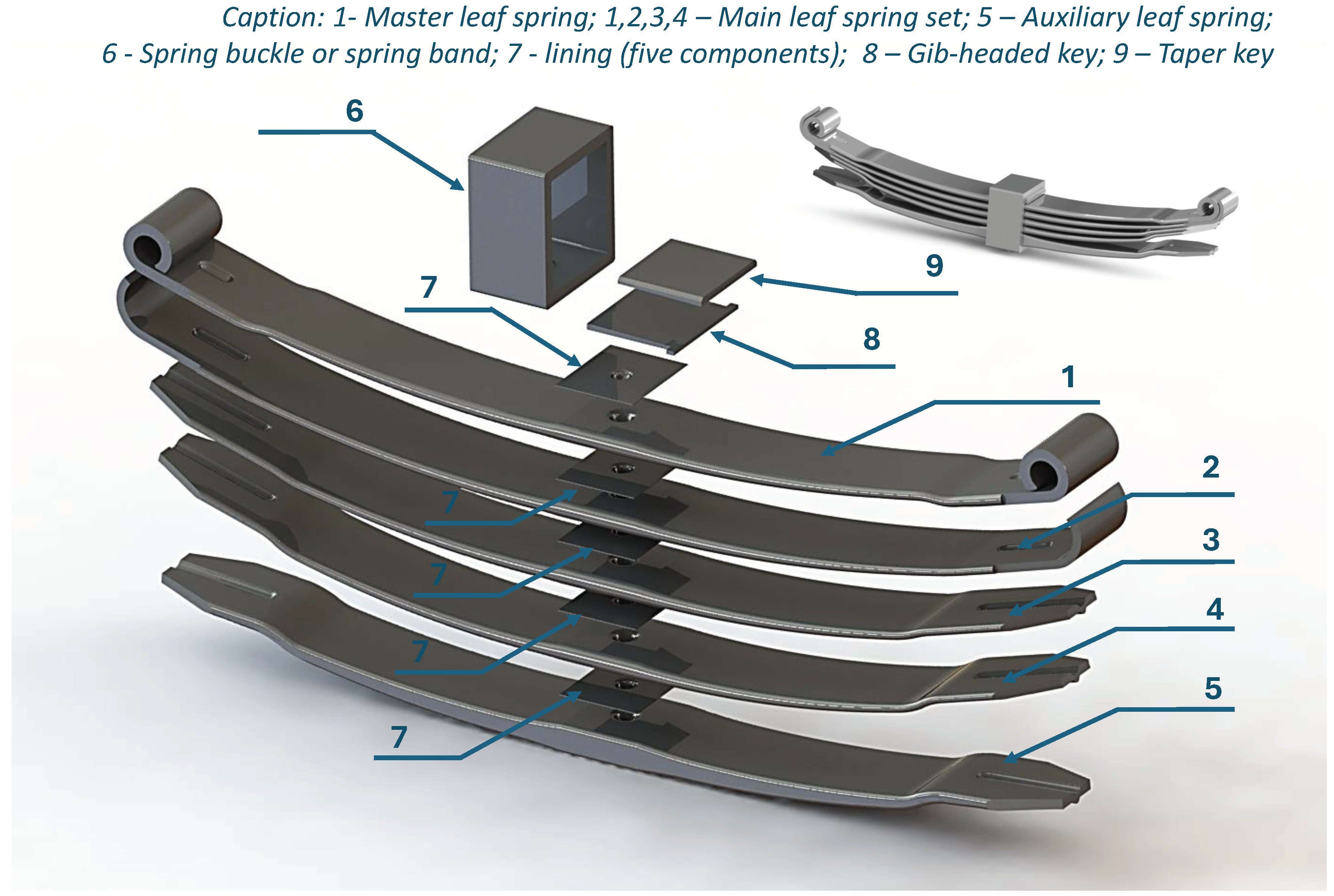
17], two spring buckle assembly processes can be considered. Nevertheless, taper-key is inserted between the spring buckle and the leaf springs, regardless of the assembling process. Introducing the taper-key, the gap existing between spring buckle’s inner face and leaf spring’s top surface is removed (see
Figure 1). Additionally, the central area of the leaf spring (connection area) is strengthened. Concerning the description of the assembling methods, in the first method, the spring buckle surfaces are expanded thermally. In the second mounting method, the taper-key and gid-headed key are introduced between the master leaf and the spring buckle under cold pressure [
18].
In the case of UIC leaf springs, they do not have fastening clamps at the ends, and hence their good operational stability will rely on the pre-stress induced by the assembly process [
17]. Pre-stress is understood as the initial deformation of the leaves which increases the contact forces on the mating surfaces. Taking into account the existence of this initial deformation caused by the assembling process and the importance that the effect of residual stresses has in the good prediction of the maximum yielding and fatigue resistances, an analysis for understanding the initial stress level presented in the parabolic leaf springs for freight wagons is carried out.
The analysis procedure consists of experimental and numerical investigations. In the experimental part, the stress relief method is used, which consists of relieving the stresses of the leaf caused by assembling by incrementally removing the spring buckle. An experimental setup is used to allow the incremental pre-strain relief of the leaves, while an acquisition system collects surface strain readings from installed electric strain gauges. This method guarantees the safety of lab people and equipment, contrary to the direct method of assembly by deforming the leaves. Regarding the computational component, a numerical model based on the finite element method is developed to simulate the assembly process. Here, a direct process is considered where the leaves are deformed incrementally until the gap between the components becomes null. Lastly, the numerical and experimental results are compared to each other for posteriorly the numerical model be used to collect a distribution of the surface bending stress over the leaf spring length. Since the distribution profile over the leaf length is determined, this profile can be used in the structural design of parabolic leaf springs for railway freight wagons.
2. Material and Methods
In determining the stress profile on the surface of the parabolic leaf spring master leaves, two approaches, experimental and numerical, are carried out. In the experimental approach, electrical strain gauges are used in the stress relief method to measure the surface deformations of the master leaf that are generated due to the assembly of the spring leaves. The stress relief method essentially consists of evaluating the variation in surface stresses throughout the spring buckle opening test until all leaves are completely relieved. In the case of the numerical approach, the method consists of numerically simulating the assembly of all the leaves up to the maximum closing displacement, which is given by the sum of the gaps between each of the leaves.
2.1. Experimental Details
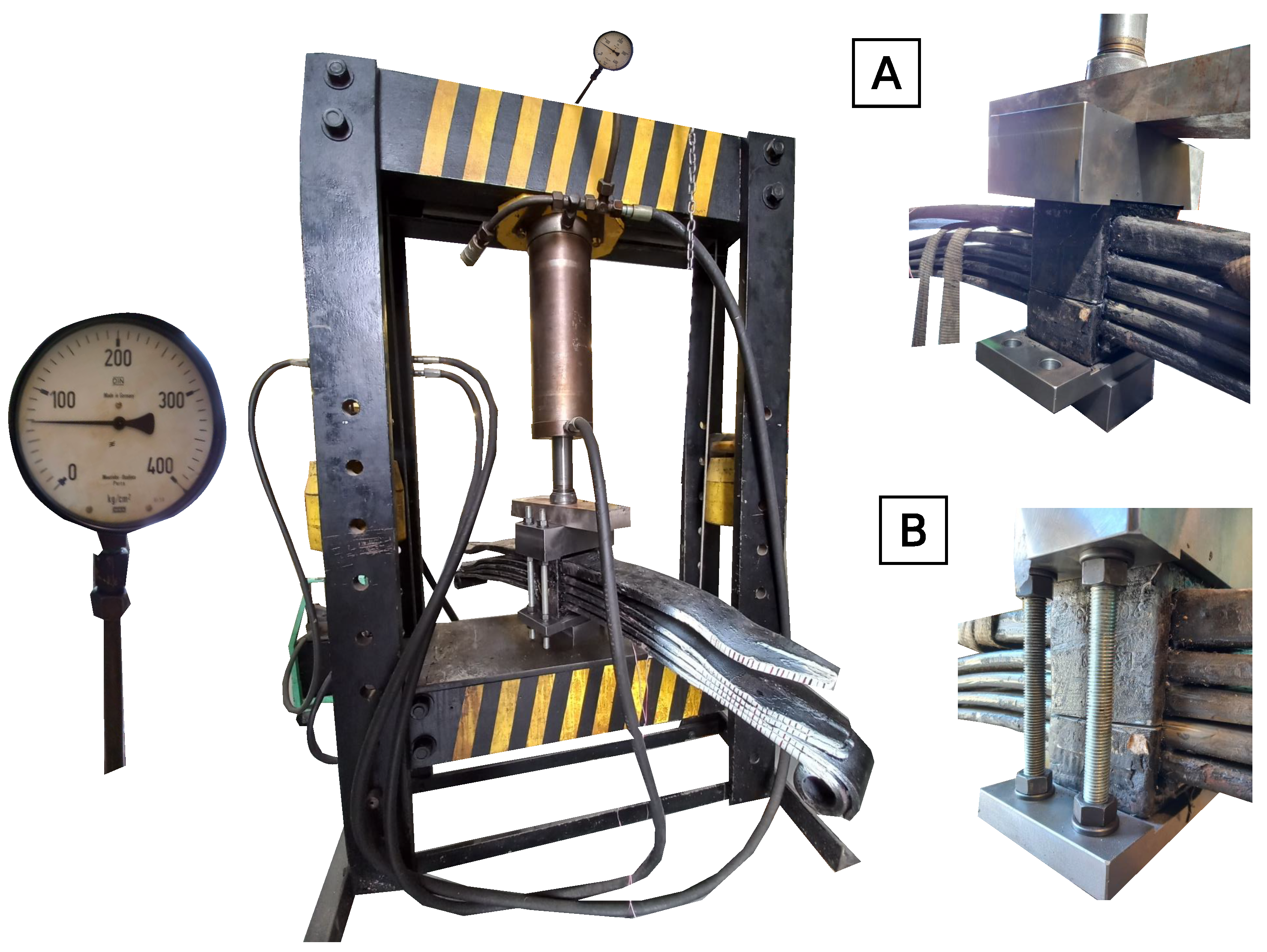
When carrying out the stress relief method, it is initially required to use a cage system that is fixed to the spring buckle of the leaf springs. This cage system is constituted of two blocks (upper and lower) and four threaded rods that fix the two blocks. Once the cage system is assembled, it is necessary to prepare the test sample. The preparation consists of creating a through-thickness cut on both sides and along the entire width of the spring buckle. In order to maintain the initial pre-stress conditions, the spring buckle tightening pressure is kept constant by applying a pressure of 70 kg/cm
2 by the hydraulic press, as shown in
Figure 2 - Left. While the hydraulic press presses the leaf spring, the two threaded rods are removed from one side. With the threaded rods removed, the spring buckle is cut. The cut is carried out in an area above the master leaf in order to prevent any damage (see
Figure 2 - A). After cutting, the two threaded rods are placed and well tightened (see
Figure 2 - B). The same procedure is performed for the other side of the spring buckle.
After the pre-preparation is done, strain gauges are glued on the main leaf surface and connected to a CATMAN SPIDER 8 acquisition system. Strain gauges with designation CEA-06-250UN-120 with 120 ± 0.3 %, and with a gauge factor of 2.105 ± 0.5% were used. These strain gauges have a gauge length, an overall length, and a matrix length of 6.35, 10.54, and 13.2 mm, respectively. Concerning their width, they have grid, overall, and matrix widths of 3.05, 3.05, and 5.6 mm, respectively. Gluing strain gauges requires prior preparation of the installation surface. The material protector, anti-corrosive paint and zinc coating (if any) and the initial surface layers were roughed with 80-grit sandpaper. A sandpaper SCP-1 Silicon Carbide Paper, 220-grit is used later for a better finish of the surface. In the strain gauge bonding procedure, a CSM-3 Degreaser was initially used, followed by MCA-1 M-Prep Conditioner and MN5A-1 M-Prep Neutralizer 5A, and finally glued with the M-bond 200 set (catalyst liquid plus adhesive liquid). After bonding the strain gauges, wire cables are welded to the terminals.
A set of 5 strain gauges were installed in specific locations to evaluate the longitudinal stress distribution with the vertical displacement imposed on the spring. The locations for bonding the strain gauges on the master leaf were decided based on the percentage of occurrence of fatigue failure (70 % in the middle zone and the remaining 30% close to the spring buckle overlap and in the central zone of the geometric notch) [
20]. Following this premise four strain gauges are glued longitudinally along the upper surface of the master leaf, in the geometric centre. An extra strain gauge is glued to the other side of the master leaf to assess the symmetry conditions (see
Figure 3).
Table 1 presents the value of the thicknesses at the strain gauges’ glue points.
2.2. Geometrical Model
In the creation of the finite element model to simulate the assembly process, the geometric information obtained after the disassembly process is used. This information essentially consists of determining the spacing between each leaf, the camber value, or radius of curvature, in addition to the geometry of the leaves.
Figure 4 presents the leaf spring geometry before the assembling process.
The effect of the different camber values,
p, of each of the leaves can be seen in
Figure 4, which shows the position of the leaves before the assembly process, with spacing between them. According to the UIC 517 standard [
17], the curvature radius of the spring leaves can be calculated using the information of the camber value.
Table 2 shows the camber value, distance
p and respective curvature radius,
, for each of the leaves, measured using the ground as a reference for the height measurement and its ends for the measurement of the longitudinal length.
Finally, all the leaves were placed together and properly aligned without any tightening to assess the gap between them (see
Figure 4). It was verified that the gap size was in the order of tens mm, which resulted in around 28 mm, a greater value than inner surfaces of the spring buckle, as shown in geometrical model represented in
Figure 4. Combining the geometry information provided by
Figure 4 and
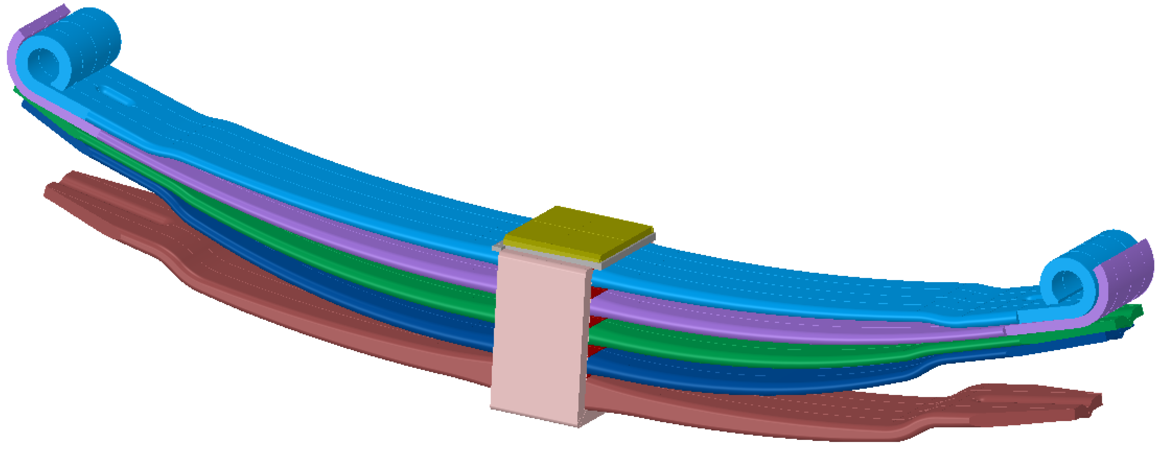
Table 2, the geometrical CAD model is of a disassembled leaf spring is developed (see
Figure 5).
2.3. Numerical Details
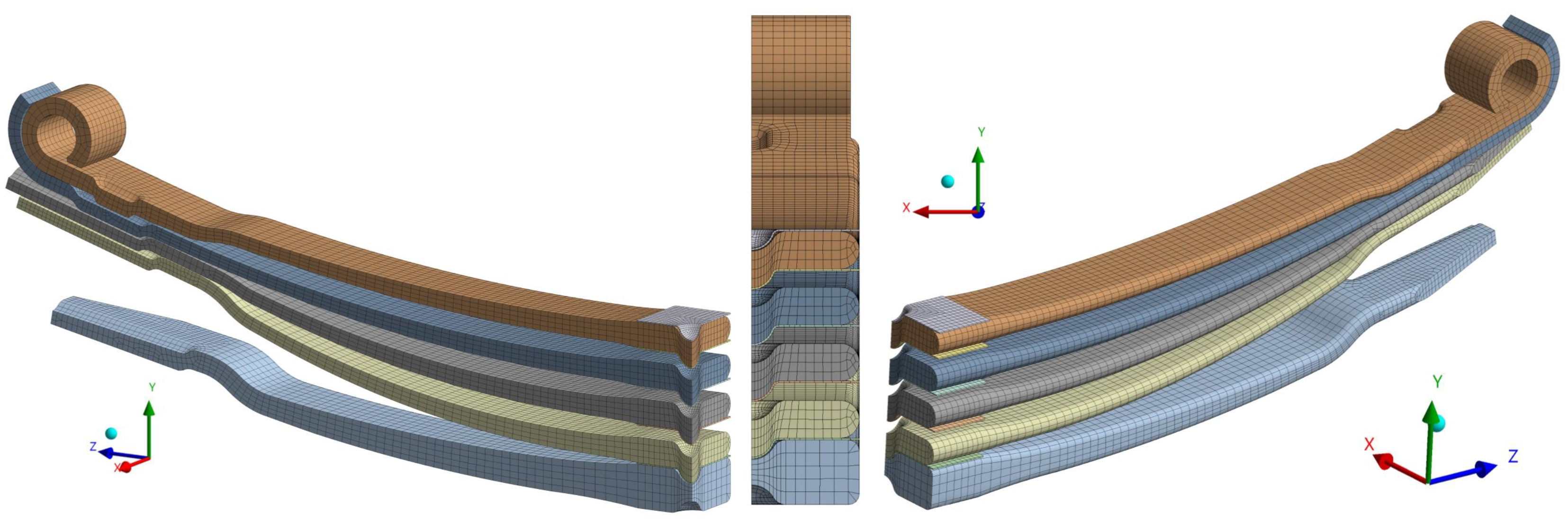
The computational model is developed in ANSYS FEM code to evaluate the distribution of the longitudinal stresses due to the assembling process. The developed numerical model only considers the five spring leaves and the spacers (linings) between them, excluding the spring buckle, taper key, and gid-headed key from the analysis to reduce the number of contact pairs (see
Figure 6).
For the investigation of the structural behaviour, the analysis problem is solved via static analysis solver with line search [
26], whose global differential equation system is written as
with
n, denoting the number of time step increments,
i denoting the iteration of the convergence process. Vectors
,
,
,
, denote respectively, the displacement vector, the external force vector, the restoring force, and the nodal contact force vector. Matrices
and
are referred to as the tangent stiffness matrix and the contact stiffness matrix, respectively. The solution of the equation system (
1) is obtained by LDLT factorization using the Sparse direct method and a Newton-Raphson procedure. The convergence criteria for the iterative process are evaluated according to the
-Norm.
The element finite formulation for a problem in analysis is assumed to be a linear elastic material with elastic constants, Young’s modulus,
E = 202.5 GPa (according to [
27]), and Poisson ratio,
= 0.29 . Geometric itineraries are represented by the contribution of the shape stiffness matrix, and the stress stiffness matrix in the tangent stiffness matrix using a corotational approach [
21,
22]. The tridimensional iso-parametric elements are brick (SOLID186), tetrahedral, and pyramidal (SOLID187) elements, and they are formulated in the displacement field with quadratic shape functions and uniform reduced integration scheme by Gauss method [
23,
24,
25]. For leaves, between 2 and 5 elements across thickness are considered whereas for the spacers, only 1 element across thickness is considered (see
Figure 6).
Regarding the contact element formulation, mating surfaces are considered to have a large deformation and sliding. Each contact pair is assigned a symmetric contact pair with surface-to-surface contact quadrilateral and triangular elements (elements CONTA174 and TARGE170 with 8 and 6 nodes), whose integration is made to the Gauss points of the element [
28,
29]. The contact symmetric numerical problem is solved via the nested augmented Lagrangian method [
30,
31] with gap function defined via pinball algorithm [
32]. The penetration tolerance is assumed to be 0.1% of the dimension perpendicular to the contact surface of the finite element and the penalty stiffness is initially assumed to be 0.1 with updating according to an adaptative scheme for each iteration
i.
Figure 7 illustrates the mating surfaces considered in the contact model of the assembling analysis.
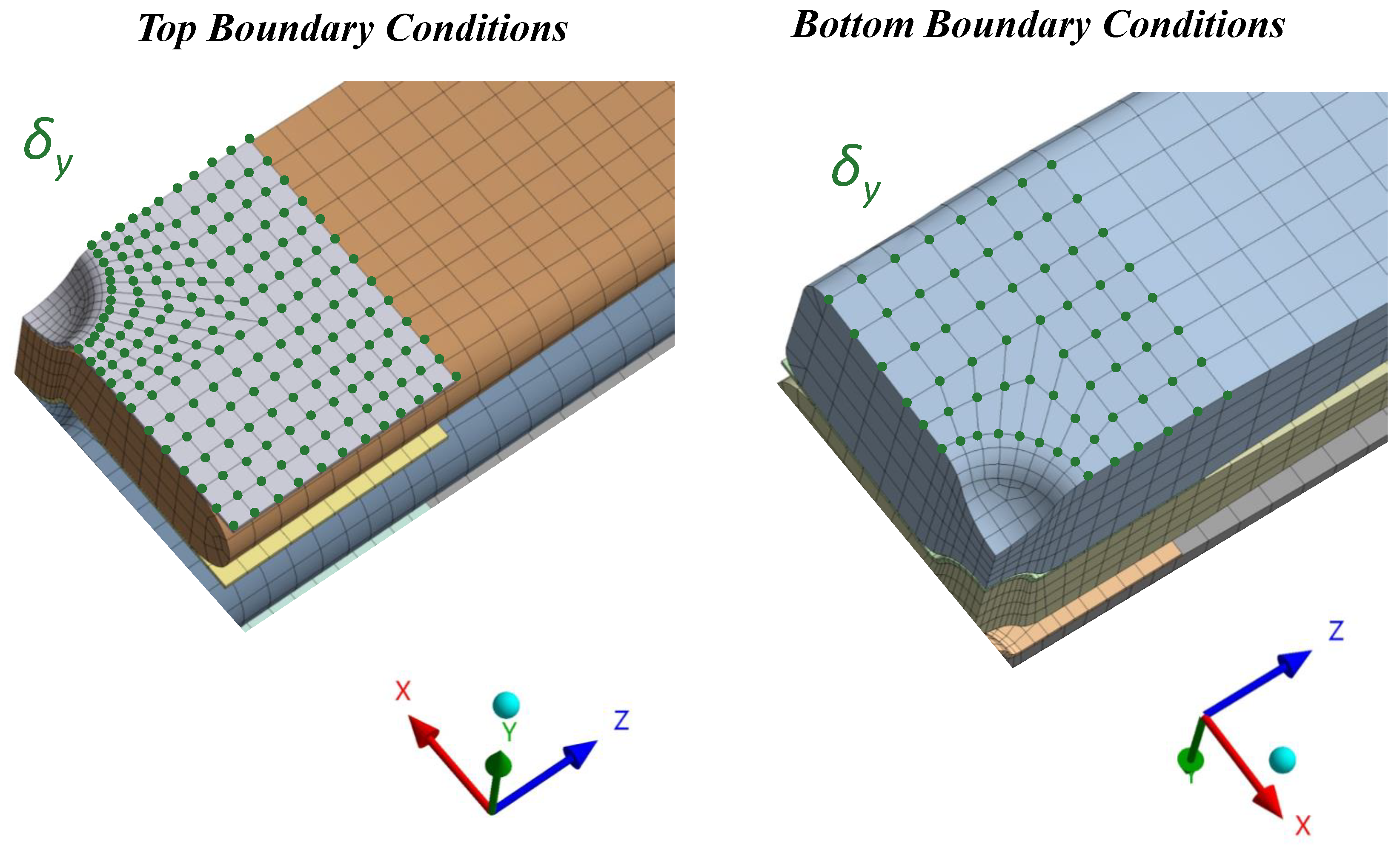
Due to the geometric and physical symmetry of the experimental model, the kinematic and boundary conditions of the numerical are represented by a 1/4 of the model, with XY and YZ symmetry planes (
Figure 8). On the top surface of master leaf and the bottom surface of the auxiliary leaf are imposed a displacement,
, with opposite directions and with a perpendicular direction to XZ plane (see
Figure 8 - "Top Boundary Conditions" and
Figure 8 - "Bottom Boundary Conditions", respectively).
3. Results and Discussion
3.1. Stress Relief Experimental Results
The experimental test by the stress relief method was carried out to determine the magnitude of the surface stresses caused by the leaf spring assembly method.
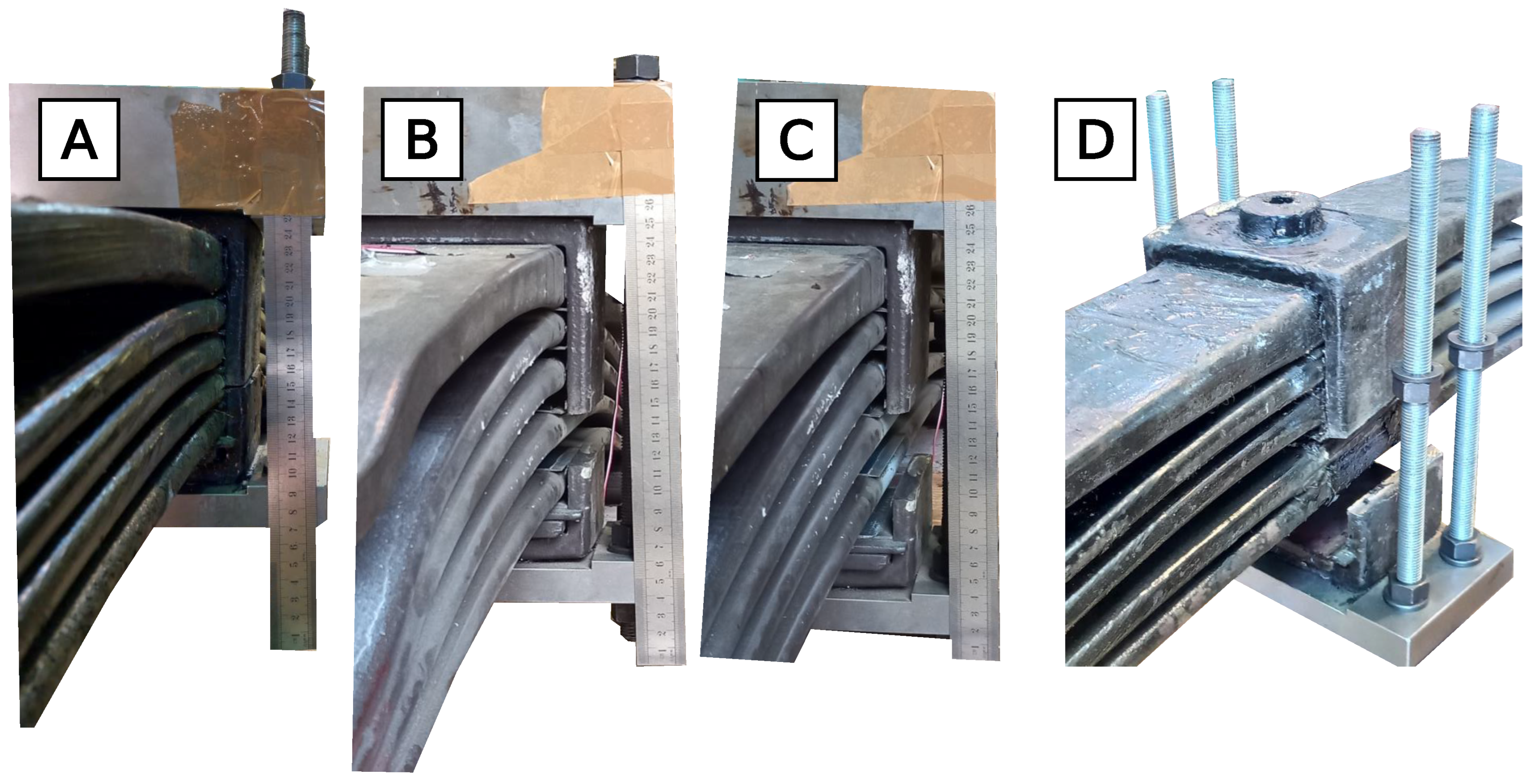
Figure 9 shows four steps related to the disassembly process of the leaf spring. In each image, a ruler is placed to identify the assembly displacement that the leaf springs are subjected to. As shown in
Figure 9 - A and C, the reference zero point corresponds to 25 mm with a maximum displacement greater than 55 mm.
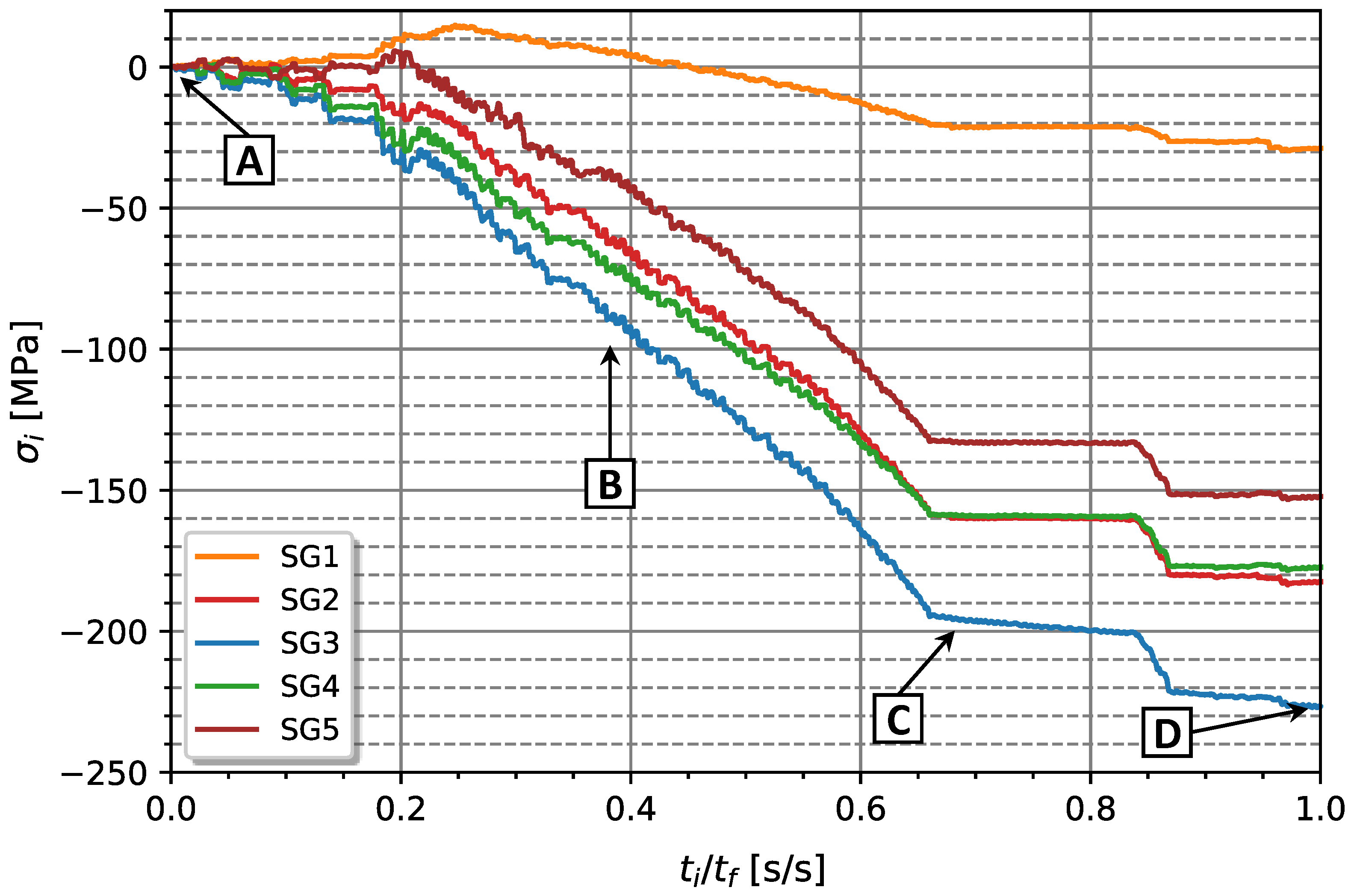
Figure 10 show the evolution of surface stress during the disassembling process. The instant time,
, was normalised by the maximum test time,
, performed in the unscrewing operation. The instant stress,
, is obtained by applying the Hooke’s law to the surface strain, assuming the same Young’s modulus considered in the numerical model (
E = 202500 MPa). From the analysis of
Figure 10 and taking into account
Figure 9, it can be seen that in the initial opening phase (point A), longitudinal stresses have less variation than in the second phase (point B). This occurs due to the high elastic energy absorbed in the spring assembling and that is exerting pressure against the cage system. As the threaded rods are loosened, the leaves have more space to recover its to its original (undeformed) position, resulting in an increase in compressive strain in the strain gauges. The smallest variation in the final stages (points C and D) corresponds to the moments of removal of the upper and lower blocks and when the spring leaves are almost completely relieved.
According to the analysis based on
Figure 10, the strain gauge Sg.1 exhibited a much lower deformation than the other strain gauges, around 28.74 MPa. On the other hand, the Sg.3 strain gauge proved to be the one with the highest deformation level during the disassembly process, with a longitudinal stress in the order of -226.62 MPa. In addition, strain gauges Sg.4 and Sg.5 exhibited very close surface stresses, -177.25 and -152.19 MPa, respectively. The result provided by Sg.4 and Sg.5 shows that the disassembly process was carried out almost uniformly. In addition, the results seem to be consistent with a structural beam model, where its ends have lower stress levels than the intermediate zones.
3.2. Assembling Procedure by Numerical Methods
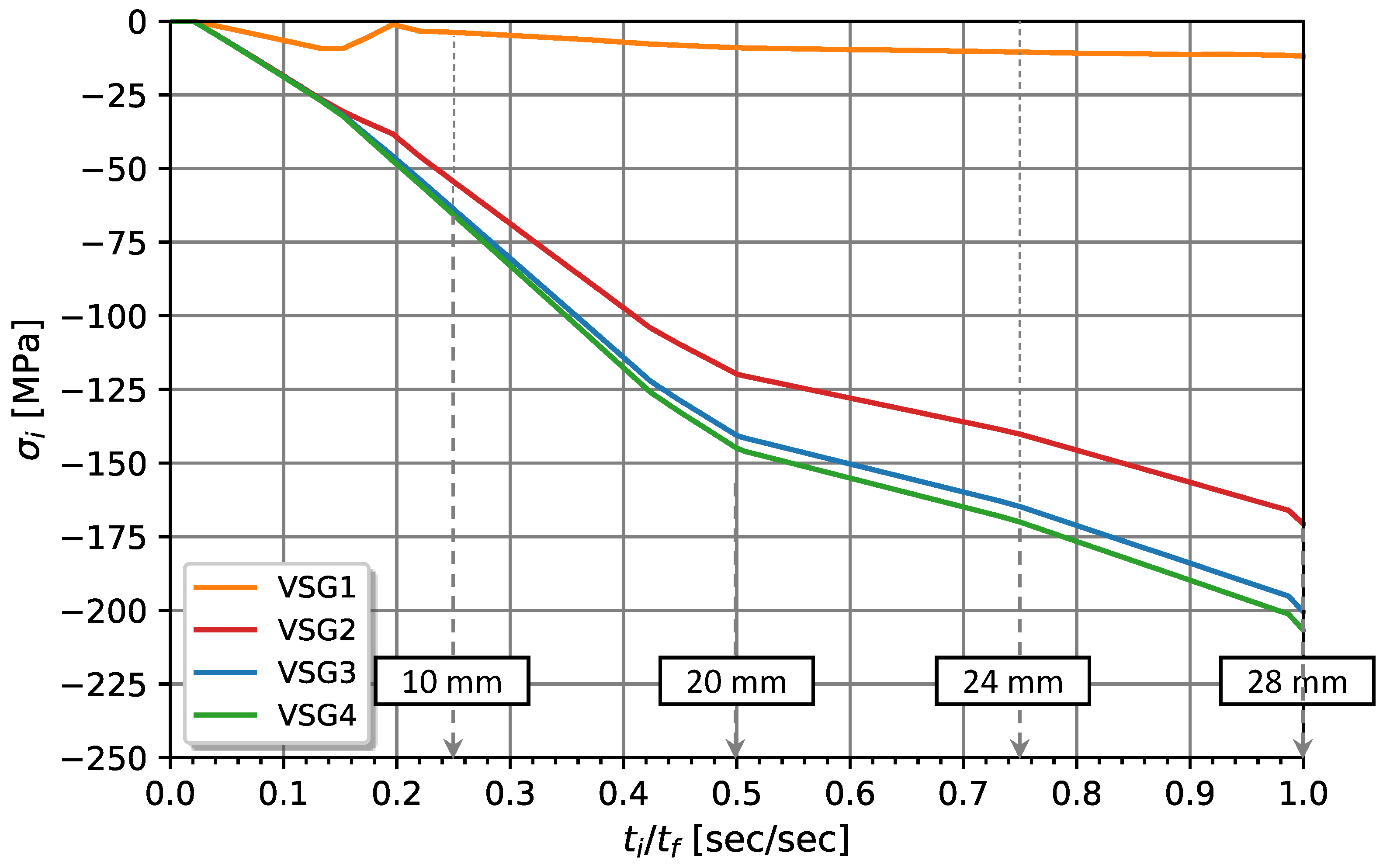
The computational model described previously was used to determine the surface stress profile over the main spring leaf length. Initially, the results obtained by the computational method were compared with the experimental results of the stress relief method for the locations measured by the strain gauges. This comparison was performed considering virtual strain gauges created in the computational model with a gauge length of 6.35 mm and an overall width of 3.05 mm according to the strain gauges data sheet used in the experimental work.
Figure 11 presents the surface stress variation by assembling along testing time evaluated considering virtual strain gauges. According to the results presented in
Figure 11, Sg.1 is the virtual strain gauge that undergoes the lowest stress level. On the other hand, the virtual strain gauges closer to the geometric centre of the leaf exhibited the highest stress level.
Table 3 presents the results obtained via the experimental model, the results obtained via the computational model, and the comparison of assembling stress values in the different positions of the strain gauges applied to the master leaf spring. From the analysis of
Table 3 it is verified that the strain gauge Sg.1 is effectively one that exhibits less deformation. The relative difference between numerical and experimental models for Sg.1 is 59.57 %. On the other hand, the strain gauges furthest from the end of the master leaf were those that exhibited the lowest difference between the analysis methods, with the extremes occurring at Sg.4 (-16.63 %).
3.3. Assembling Surface Stress Profile
Once the computational model is validated by the experimental model, it is possible to consider the computational model to provide additional information.
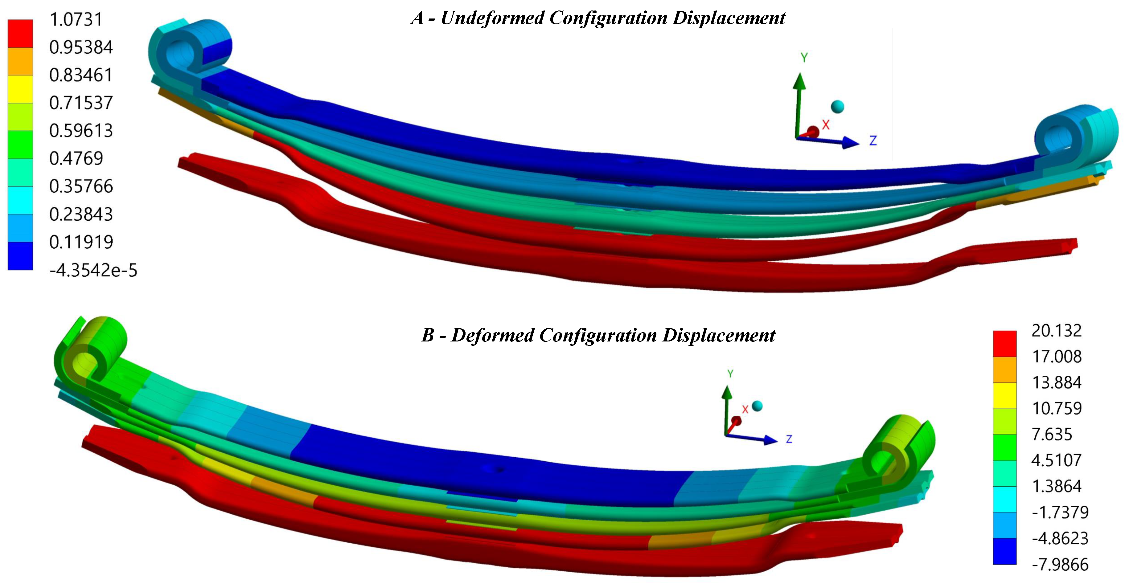
Figure 12 shows the deformed configuration of the leaf spring after assembling the leaves in contrast to the undeformed configuration before the assembling procedure.
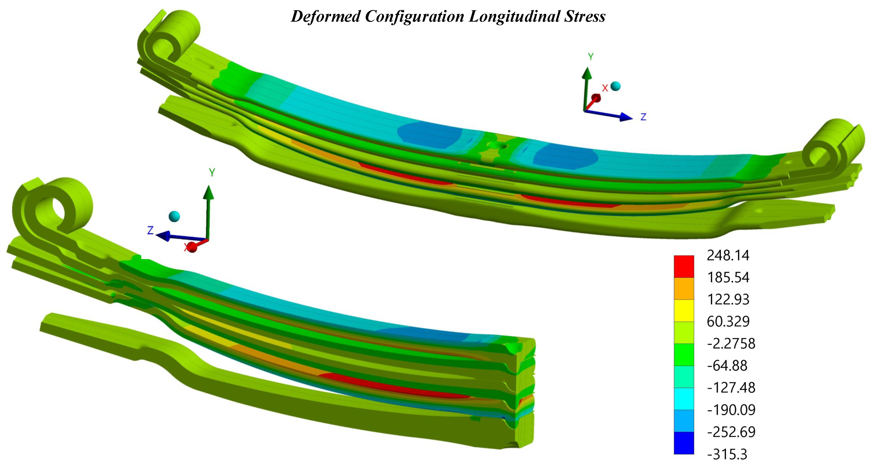
The imposed assembling displacement induces different bending stresses in the spring leaves. For example, in the outermost leaf, indicated as number 1 and number 4, the bending effect is more pronounced than in the central leaves, number 2 and number 3. Regarding leaf 4, the top surface is usually stressed under tension, as opposed to leaf 1, whose top surface is subject to compression. Notice that this compressive effect on the master leaf was verified in the results obtained experimentally. Furthermore, the same structural behaviour for leaves 1 and 4 was observed in [
33].
Figure 13 presents the longitudinal stress magnitude in the leaves at the end of the assembling test. It is interesting to point out that the maximum and minimum stresses verified in the plot are of the same order of magnitude, namely above 200 MPa, both for compressive and tension states.
Figure 13 illustrates the variation of stress along the thickness and length of the master leaf.
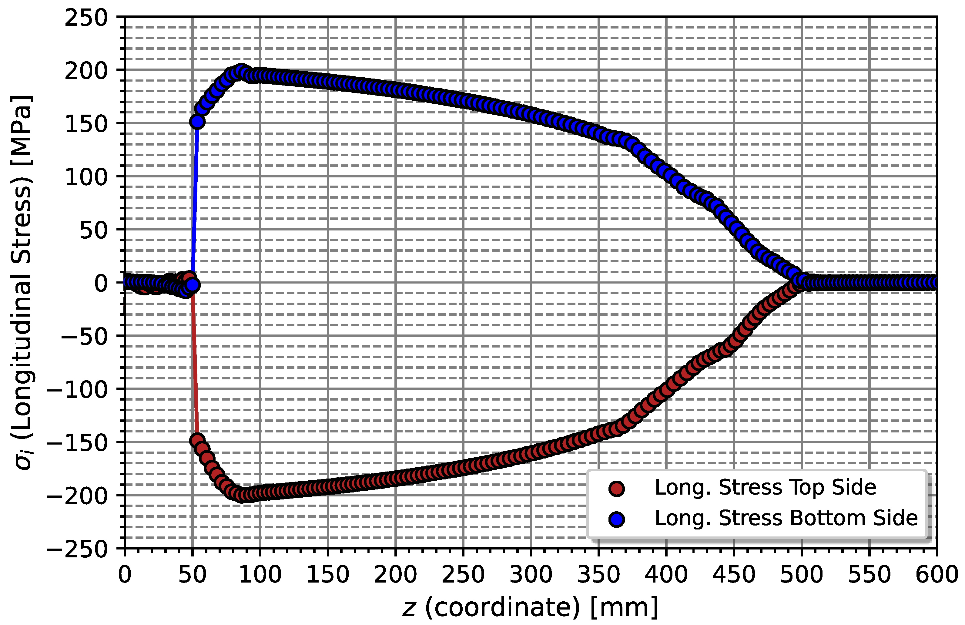
In order to analyse the profile of assembly stresses on the master leaf, the magnitude of the surface stress on the top and bottom surface of the master leaf is compared as shown in
Figure 14. It is possible to state that there is a symmetrical effect of the magnitude of surface stress. Furthermore, the maximums and minimums occur in the zone close to the initiation of the spring buckle overlap and geometric shape change, [50 - 100 mm]. For length coordinate values less than 50 mm, the stress level is practically null due to the compressive displacement boundary conditions applied to this zone. On the other hand, for values of coordinates of
mm, the surface stress on both sides tends to decrease, in magnitude up to the point of
z = 500 mm. For values of
z greater than 500 mm, the surface stress remains zero. A similar stress profile of a Bernoulli’s cantilever beam was observed in an experimental test rig of single parabolic leaf springs. In [
34,
35], spring leaves were clamped with rigid blocks not allowing deformation of the leaf in the clamped zone.
4. Conclusions
The initial state of stresses due to the assembly process of the leaf springs was investigated. The determination of stresses generated by the assembly process was analysed using an inverse stress relaxation method denominated as the stress relief method. Strain gauges were used to measure surface deformations in the leaf spring. The master leaf was considered for analysis because it is the leaf with the highest probability of failure and because of the ease of installation of the strain gauges. Five strain gauges were placed in different positions along the length of the spring master leaf. The fifth strain gauge was glued on the opposite side to identify the symmetry of stresses associated with the assembly process.
The results obtained by the experimental model were used to validate the numerical model. The numerical model developed simulated the assembly of the leaf springs from their undeformed configuration to their deformed configuration. Thus, the consideration of two methods of opposing procedures allowed the reciprocal validation of numerical and experimental results.
According to the experimental results, the data collected by strain gauges showed that the highest deformation values occur for the positions of 285 mm in relation to the geometric centre that corresponds to the middle zone of the leaf. However, the strain gauge placed in this position showed some measurement anomalies at the beginning of the test. In addition, the electric strain gauges showed the existence of stress symmetry.
As regards the comparison with the numerical results, it was demonstrated that the highest stress measurement error is located in the zone closest to the ends. However, for the zones closest to the geometric centre, a maximum error of -16.63 % was exhibited. The numerical model proved to be in agreement with that presented in the literature, showing that upper leaves set undergo a greater deformation than inner leaves and the stress level also relies on the pre-deformed curvature of the leaf. Additionally, it was verified that the top surface of the fourth leaf is subjected to a tension state whereas the top surface of the master leaf is subjected to compression. Thus, the validated numerical model allows obtaining a stress state profile along the length of the master leaf, such that it is verified a null stress in the overlapped zone and a maximum stress occurs in the geometric change (to parabolic shape), approximately 100 mm from the centre. For greater lengths, bending stress tends to decrease.
Author Contributions
Conceptualization, Gomes V.M.G.; methodology, Gomes V.M.G. and Figueiredo M.A.V. ; software, Gomes V.M.G. and Figueiredo M.A.V.; validation, Gomes V.M.G., de Jesus A.M.P.; formal analysis, Gomes V.M.G.; investigation, Gomes V.M.G.; resources, Figueiredo M.A.V., Correia J.A.F.O. and de Jesus A.M.P.; data curation, Gomes V.M.G. and Figueiredo M.A.V.; writing—original draft preparation, Gomes V.M.G.; writing—review and editing, Gomes V.M.G., Figueiredo M.A.V., Correia J.A.F.O. and de Jesus A.M.P.; visualization, Gomes V.M.G., Figueiredo M.A.V. and de Jesus A.M.P.; supervision, Figueiredo M.A.V., Correia J.A.F.O. and de Jesus A.M.P.; project administration, de Jesus A.M.P.; funding acquisition, Correia J.A.F.O. and de Jesus A.M.P.
Institutional Review Board Statement
Not applicable
Informed Consent Statement
Not applicable
Data Availability Statement
The data presented in this study are available on request from the corresponding author. The data are not publicly available due to privacy restrictions.
Acknowledgments
The authors also want to express a special thanks to the Doctoral Programme iRail - Innovation in Railway Systems and Technologies funded by the Portuguese Foundation for Science and Technology, IP (FCT) through the PhD grant (PD/BD/143141/2019); and the following Research Projects: FERROVIA 4.0, with reference POCI-01-0247-FEDER-046111, co-financed by the European Regional Development Fund (ERDF), through the Operational Programme for Competitiveness and Internationalization (COMPETE 2020), under the PORTUGAL 2020 Partnership Agreement; SMARTWAGONS - DEVELOPMENT OF PRODUCTION CAPACITY IN PORTUGAL OF SMART WAGONS FOR FREIGHT with reference nr. C644940527-00000048, investment project nr.27 from the Incentive System to Mobilising Agendas for Business Innovation, funded by the Recovery and Resilience Plan and by European Funds NextGeneration EU; and PRODUCING RAILWAY ROLLING STOCK IN PORTUGAL, with reference nr. C645644454-00000065, investment project nr. 55 from the Incentive System to Mobilising Agendas for Business Innovation, funded by the Recovery and Resilience Plan and by European Funds NextGeneration EU.
Conflicts of Interest
The authors declare no conflict of interest.
References
- Zhao, W. Y.; Wei, L.; Wang, J. F.; Wang, J.; Gu, X. S.; Song, C. Study on the modeling method of leaf spring based on assembly pre-stress. Advanced Materials Research. 2013, 663, 545–551. [Google Scholar] [CrossRef]
- Arora, V. K.; Bhushan, G.; Aggarwal, M. L. Fatigue life assessment of 65Si7 leaf springs: a comparative study. International scholarly research notices. 2014. [Google Scholar] [CrossRef]
- Kong, Y. S.; Omar, M. Z.; Chua, L. B.; Abdullah, S. Explicit nonlinear finite element geometric analysis of parabolic leaf springs under various loads. The Scientific World Journal. 2013. [Google Scholar] [CrossRef]
- Refngah, F. N. A.; Abdullah, S.; Jalar, A.; Chua, L. B. Behaviour Study and FEA-Based Fatigue Simulation on Parabolic Leaf Spring. Key Engineering Materials. 2011, 462, 419–424. [Google Scholar] [CrossRef]
- Krason, W.; Hryciow, Z.; Wysocki, J. Numerical studies on influence of friction coefficient in multi-leaf spring on suspension basic characteristics. AIP Conference Proceedings. 2019, 2078(1), 545–551. [Google Scholar] [CrossRef]
- Krason, W.; Wysocki, J.; Hryciow, Z. Dynamics stand tests and numerical research of multi-leaf springs with regard to clearances and friction. Advances in Mechanical Engineering. 2019, 11(5), 545–551. [Google Scholar] [CrossRef]
- Ali, N.; Riantoni, R.; Putra, T. E.; Husin, H. The fracture of two-layer leaf spring: Experiments and simulation. IOP conference series: materials science and engineering. IOP Publishing, 0120; 46. [Google Scholar] [CrossRef]
- Husaini, H.; Anshari, R.; Ali, N.; Yunus, J. The analysis of the failure of leaf spring used as the rear suspension system in 110 PS diesel trucks. In AIP Conference Proceedings, 2613. [Google Scholar] [CrossRef]
- Fuentes, J. J.; Aguilar, H. J.; Rodríguez, J. A.; Herrera, E. J. Premature fracture in automobile leaf springs. Engineering Failure Analysis. [CrossRef]
- Husaini, H.; Farhan, M.; Ali, N.; Putra, T. E.; Anshari, R. , Analysis of the Leaf Spring Failure in Light Duty Dump Truck. Key Engineering Materials; 2022, 930, 43–52. [Google Scholar] [CrossRef]
- Deulgaonkar, V. R.; Rode, M.; Katwate, S.; Mandge, A.; Patil, A.; Makode, Y. Failure analysis of leaf spring used in transport utility vehicles. Journal of Failure Analysis and Prevention, 1844. [Google Scholar] [CrossRef]
- Chen, Y. H.; Chen, G. C.; Wu, C. T.; Lee, C. L.; Chen, Y. R.; Huang, J. F.; Hsiao, K. H.; Lin, J. I. Object investigation of industrial heritage: The forging and metallurgy shop in Taipei railway workshop. Applied Sciences 2020, 10(7), 2408. [Google Scholar] [CrossRef]
- Matej, J.; Seńko, J.; Awrejcewicz, J. Dynamic properties of two-axle freight wagon with uic double-link suspension as a non-smooth system with dry friction. In Applied Non-Linear Dynamical Systems. Springer International Publishing. [CrossRef]
- Piotrowski, J. Model of the UIC link suspension for freight wagons. Archive of Applied Mechanics 2003, 73, 517–532. [Google Scholar] [CrossRef]
- Hoffmann, M.; True, H. Dynamics of two-axle railway freight wagons with UIC standard suspension. Vehicle System Dynamics 2006, 44, 139–146. [Google Scholar] [CrossRef]
- Iwnicki, S. D.; Stichel, S.; Orlova, A.; Hecht, M. Dynamics of railway freight vehicles. Vehicle system dynamics. Vehicle System Dynamics 2015, 53(7), 995–1033. [Google Scholar] [CrossRef]
- UIC 517, Wagons - Suspension Gear - Standardisation. International Union of Railways 2007.
- ISO 683-14, Heat-treatable steels, alloy steels and free-cutting steels Part 14: Hot-rolled steels for quenched and tempered springs. European Committee for Standardization, Brussels.
- Gomes, V. M. G.; Marques, M. J.; Figueiredo, M.; Correia, J. A. F. O.; Batista, A. C.; Calçada, R. , de Jesus, A. M. P. Experiments for the Quantification of the Initial Stress State in UIC Parabolic Leaf Springs. Procedia Structural Integrity 2023, 48, 142–148. [Google Scholar] [CrossRef]
- Petrovi, D.; Bii Gai, M.; Savkovi, M. Increasing the efficiency of railway transport by improvement of suspension of freight wagons. Promet-Traffic Transp. 2012, 24, 487–493. [Google Scholar] [CrossRef]
- Rankin, C. C.; Brogan, F. A. An element independent corotational procedure for the treatment of large rotations. J. Pressure Vessel Technol. 1986, 108(2), 165–174. [Google Scholar] [CrossRef]
- Argyris, J. An excursion into large rotations. Computer Methods in Applied Mechanics and Engineering. [CrossRef]
- McMeeking, R. M.; Rice, J. R. Finite-element formulations for problems of large elastic-plastic deformation. International Journal of Solids and Structures. 1975, 11(5), 601–616. [Google Scholar] [CrossRef]
- Flanagan, D. P.; Belytschko, T. A uniform strain hexahedron and quadrilateral with orthogonal hourglass control. International journal for numerical methods in engineering. 1981, 17(5), 679–706. [Google Scholar] [CrossRef]
- Zienkiewicz, O. C.; Taylor, R. L.; Zhu, J. Z. The Finite Element Method: Its Basis and Fundamentals; Elsevier Ltd., 2013. [CrossRef]
- Schweizerhof, K. H.; Wriggers, P. Consistent linearization for path following methods in nonlinear FE analysis. Computer Methods in Applied Mechanics and Engineering 1986, 14(3), 266. [Google Scholar] [CrossRef]
- Gomes, V.M.G.; Souto, C.D. S; Correia, J. A.; de Jesus, A.M.P. Monotonic and Fatigue Behaviour of the 51CrV4 Steel with Application in Leaf Springs of Railway Rolling Stock. Metals 2024, 14(3), 266. [Google Scholar] [CrossRef]
- Cescotto, S.; Charlier, R. Frictional contact finite elements based on mixed variational principles. International Journal for numerical methods in engineering 1993, 36(10), 1681–1701. [Google Scholar] [CrossRef]
- Cescotto, S.; Zhu, Y. Y. Large strain dynamic analysis using solid and contact finite elements based on a mixed formulation: Application to metal forming. Journal of materials processing technology. [CrossRef]
- Simo, J. C.; Laursen, T. An augmented Lagrangian treatment of contact problems involving friction. Computers & Structures. [CrossRef]
- Laursen, T. A.; Simo, J. T. Algorithmic symmetrization of Coulomb frictional problems using augmented Lagrangians. Computer methods in applied mechanics and engineering. [CrossRef]
- Belytschko, T.; Neal, M. O. Contact-impact by the pinball algorithm with penalty and Lagrangian methods. International Journal for Numerical Methods in Engineering 1991, 31(3), 547–572. [Google Scholar] [CrossRef]
- Wang, T.; Tinsley, B.; Patel, M. D.; Shabana, A. A. Nonlinear dynamic analysis of parabolic leaf springs using ANCF geometry and data acquisition. Nonlinear Dynamics 2018, 93, 2487–2515. [Google Scholar] [CrossRef]
- Fragoudakis, R.; Saigal, A.; Savaidis, G.; Malikoutsakis, M.; Bazios, I.; Savaidis, A.; Pappas, G.; Karditsas, S. Fatigue assessment and failure analysis of shot-peened leaf springs. Fatigue Fract. Eng. Mater. Struct. 2013, 36, 92–101. [Google Scholar] [CrossRef]
- Savaidis, G.; Karditsas, S.; Savaidis, A.; Fragoudakis, R. Microstructural, surface and fatigue analysis of stress peened leaf springs. International Journal of Structural Integrity 2015, 6(5), 589–604. [Google Scholar] [CrossRef]
Figure 1.
Illustration of an assembled and a disassembled UIC parabolic leaf spring and the identification of its respective structural and assembly components.
Figure 1.
Illustration of an assembled and a disassembled UIC parabolic leaf spring and the identification of its respective structural and assembly components.
Figure 2.
Illustration of the experimental setup needed to prepare the test sample: Left - Hydraulic Press at 70 bar, Right A - Screw removal and spring buckle cutting, Right B - Screw replacement [
19].
Figure 2.
Illustration of the experimental setup needed to prepare the test sample: Left - Hydraulic Press at 70 bar, Right A - Screw removal and spring buckle cutting, Right B - Screw replacement [
19].
Figure 3.
Location of the five strain gauges used to measure the assembling stresses in the master leaf.
Figure 3.
Location of the five strain gauges used to measure the assembling stresses in the master leaf.
Figure 4.
Leaf spring geometry before the assembling process.
Figure 4.
Leaf spring geometry before the assembling process.
Figure 5.
Geometrical representation of a disassembled leaf spring.
Figure 5.
Geometrical representation of a disassembled leaf spring.
Figure 6.
Geometrical representation of a disassembled leaf spring.
Figure 6.
Geometrical representation of a disassembled leaf spring.
Figure 7.
Representation of the definition of the mating surfaces used to the contact model.
Figure 7.
Representation of the definition of the mating surfaces used to the contact model.
Figure 8.
Representation of the boundary conditions applied in the symmetric finite element model, which represents the experimental assembling test of a parabolic leaf spring.
Figure 8.
Representation of the boundary conditions applied in the symmetric finite element model, which represents the experimental assembling test of a parabolic leaf spring.
Figure 9.
Representation of the time steps corresponding to the
Figure 10 of the stress relief method.
Figure 9.
Representation of the time steps corresponding to the
Figure 10 of the stress relief method.
Figure 10.
Variation of the surface stress by assembling along testing time.
Figure 10.
Variation of the surface stress by assembling along testing time.
Figure 11.
Variation of the assembling surface stress along testing time evaluated considering virtual strain gauges.
Figure 11.
Variation of the assembling surface stress along testing time evaluated considering virtual strain gauges.
Figure 12.
Representation of the undeformed configuration, at the beginning of the test, and the deformed configuration at the end of the testing after the leaves assembled.
Figure 12.
Representation of the undeformed configuration, at the beginning of the test, and the deformed configuration at the end of the testing after the leaves assembled.
Figure 13.
Representation of the longitudinal stress magnitude in the leaves at the end of assembling test.
Figure 13.
Representation of the longitudinal stress magnitude in the leaves at the end of assembling test.
Figure 14.
Bending stress profile of assembly stresses on the master leaf, on the tension and compression sides.
Figure 14.
Bending stress profile of assembly stresses on the master leaf, on the tension and compression sides.
Table 1.
Thickness of the cross-section in the position of the strain gauges applied on the surface of the master leaf.
Table 1.
Thickness of the cross-section in the position of the strain gauges applied on the surface of the master leaf.
| Dimension [mm] |
Leaf Spring N |
| Position |
1 |
2 |
3 |
4 |
5 |
| Thickness, (h) |
13.45 |
13.50 |
17.20 |
18.05 |
17.85 |
| Length, (z) |
490 |
285 |
130 |
80 |
-110 |
Table 2.
Camber value, p, measured for each leaf and respective curvature radius, .
Table 2.
Camber value, p, measured for each leaf and respective curvature radius, .
| Leaf Spring |
|---|
| Number and Name |
Master (nº1) |
SlaveI (nº2) |
SlaveII (nº3) |
SlaveIII (nº4) |
Auxiliary (nº5) |
| Camber, p[mm] |
107 |
140 |
102 |
123 |
61 |
| Curvature radius, [mm] |
1735 |
1665 |
1555 |
1325 |
1660 |
Table 3.
Comparison of assembling stress values in the different positions of the strain gauges applied to the master leaf spring.
Table 3.
Comparison of assembling stress values in the different positions of the strain gauges applied to the master leaf spring.
| Strain Gauge |
Sg.1 |
Sg.2 |
Sg.3 |
Sg.4 |
Sg.5 |
| Experimental [MPa] |
-28.74 |
-182.40 |
-226.62 |
-177.25 |
-152.19 |
| Numerical [MPa] |
-11.62 |
-166.07 |
-195.20 |
-206.72 |
- |
| Error [%] |
59.57 |
8.952 |
13.86 |
-16.63 |
- |
|
Disclaimer/Publisher’s Note: The statements, opinions and data contained in all publications are solely those of the individual author(s) and contributor(s) and not of MDPI and/or the editor(s). MDPI and/or the editor(s) disclaim responsibility for any injury to people or property resulting from any ideas, methods, instructions or products referred to in the content. |
© 2024 by the authors. Licensee MDPI, Basel, Switzerland. This article is an open access article distributed under the terms and conditions of the Creative Commons Attribution (CC BY) license (https://creativecommons.org/licenses/by/4.0/).
