Introduction
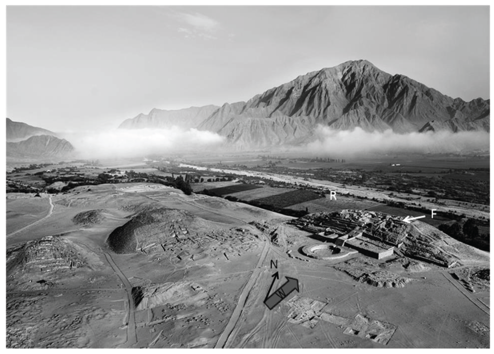
In the Late Archaic Period (5,000 to 3,750 Before Present), monumental architecture and the largest urban settlements in the Western Hemisphere flourished in the Supe Valley and adjacent desert drainages of the Peruvian coast (Shady 2006; Shady 2009; Sandweiss et al. 2009). Caral, spanning over 65 hectares and including six large pyramids, numerous smaller platform mounds, a variety of residential architecture, and two sunken circular plazas, was the largest of these settlements (Shady et al. 2001). A general view of Caral in the Supe River Valley and of the largest pyramid, Picramide Mayor, is shown in Figure 1A.
Figure 1A.
Aerial view. Panel A in the front page depicts the setting of Caral in its surroundings with the relative location of the Fogón Mayor (F) and Supe River (R, which flows right to left in the photograph) and its fertile valley, with mountains in the background. Arrows indicate North (N) and the contemporary prevailing winds (W).
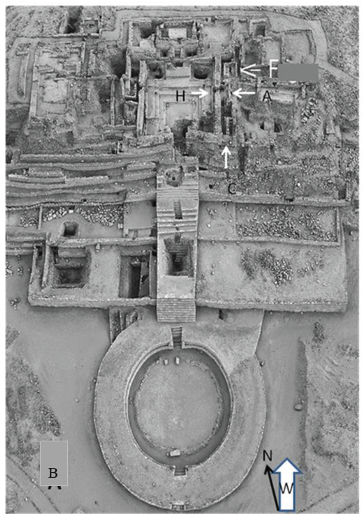
Figure 1.
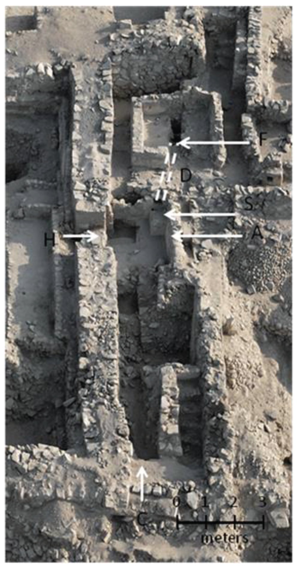
Panel B shows detail of the pyramid top indicating the relative locations of the fire pit (F), the corridor (C) and the antechamber (A) with hinged doors (H). All photographs were taken with either a 4x5 view camera fitted with a 150 mm lens or a Nikon D800E. All photographs were color balanced with a standard gray card and enhanced by Photoshop CS6 computing software.
Radiocarbon analysis from a variety of contexts at Caral provides a range of uncalibrated dates between 4,090 + 90 and 3,640 + 50 years ago. After calibration, these dates corresponded to a 600-year period ca. 2,700 and 2,000 cal B.C. (Shady et al. 2001). The absence of ceramic, metallurgical or loom-woven artifacts discovered in the archaeological excavations has hindered empirical understanding of the technological development of this early society. However, this apparent under-development in technological disciplines, as evidenced by the lack of respective artifacts, is contradicted by the very sophisticated and complex monumental architecture at Caral. (Shady 2006; Shady and Kleihege 2008). Dispersed among these architectural monuments are a number of architectonically diverse fire pits (or “fogones”), some without any ventilation structure that would increase airflow and others where air was fed into the fire pit by one or by two underground air ducts. Considering the general assumption that there were neither ceramics nor metallurgy in Caral or in archaic coastal Peru (Shady 2006; Sandweiss et al. 2009), several alternative roles of these fogones have been proposed. The most generally accepted role for the fogones revolves around collective ceremonies where offerings were burnt to produce sacred smoke that elevated towards the gods. This hypothesis seems to relate to Inca customs witnessed by early Spanish chroniclers several thousand years after Caral was abandoned (Jones 2008). Religion appears as an imaginative justification to monumental construction, however, there is no evidence supporting the general belief that the main pyramid of Caral played a religious role.
In the present work, we focused on the main fogón (the fire pit and related structures) located at the top of Caral’s largest pyramid, Pirámide Mayor. This structure was uncovered by the investigations ongoing at Caral since 1994 under the direction of Dr. Ruth Shady (Shady and Machacuy 2000). The location of this fogón (named here “Fogón Mayor”) relative to other structures on top of Pirámide Mayor is shown in Figure 1B. The corridor and ancillary structures have previously been proposed to have served as deposit or walkway (Shady and Machacuy, 2000). The goal of our study was to investigate whether a “sacred smoke” role best explained Fogón Mayor, taking into consideration the construction techniques, the complex architectural design, the ventilation system and its placement on top of Pirámide Mayor. To this end we applied widely accepted engineering principles in aerodynamics and thermodynamics to calculate and model the air-flow characteristics of this sophisticated fogón. We divided the technical analysis of the Fogón Mayor into two key lines of study: i) analysis of the air-flow characteristics influenced by its location on top of the pyramid and by the design of the corridors and ducts introducing air to the fire pit and ii) estimation of the heat generation capabilities, heat losses and potential operating temperature of the combustion chamber of the fogón itself. Estimating the airflow that the fogón would receive under various wind conditions was considered to be the determinant factor to any combustion in the fogón (assuming that fuel was a set parameter, almost certainly wood or other cellulosic material). Therefore, air-flow is the subject of the present manuscript. The subject of the second key process (combustion) requires a separate study and a different team of scientists and therefore, will be dealt in a following report. A summary of all these findings was presented at The 82nd Annual Meeting of the Society for American Archaeology (Sagripanti et. al. 2018).
Archaeological Context
The
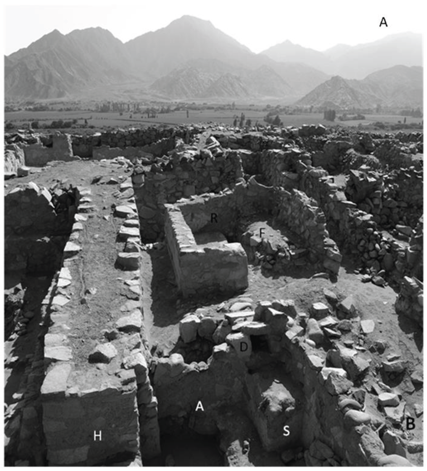
Fogón Mayor is part of a stone architectonic unit that includes a central space with a fire pit and is surrounded by a wall with auxiliary components that include a platform, small rooms, and a corridor (as depicted in
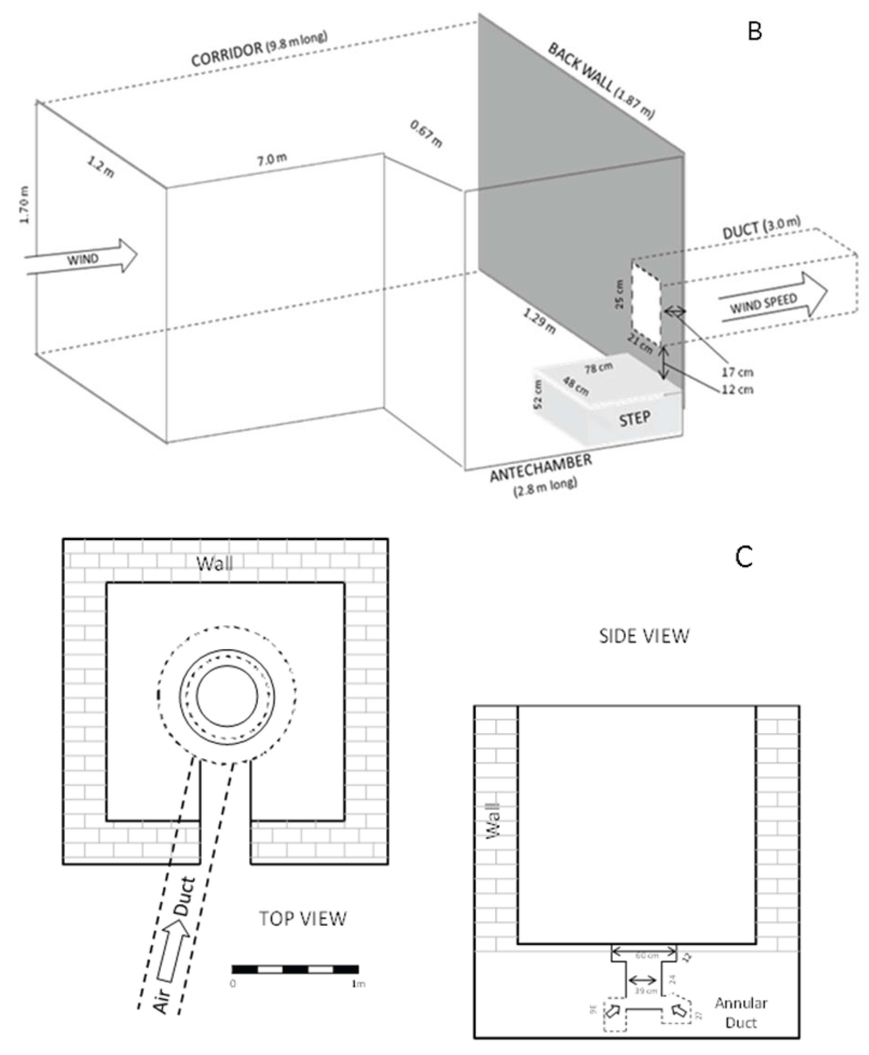
Figure 2A). The dimensions of the unit were previously reported (Shady and Machacuy, 2000).
These authors posited that the structure had walls approximately 1.7 meters in height and was covered by a light roof. Shady and Machacuy also reported the dimensions of the corridor, antechamber and duct that ventilated the fire pit (schematized in
Figure 2B). The corridor, which begins at the facade of
Pirámide Mayor and ends in the antechamber, is 1.2 m wide. The enlarged space of the antechamber is 1.87 m wide and contains some remains that indicate the presence of hinged doors. It also holds a stone step, 48 cm wide, 78 cm deep and 52 cm wide, which sits at the mouth of the underfloor duct. This duct, 3 m in length and varying in cross-section dimensions from 21 cm to 25 cm, connects the antechamber to an annular cavity that surrounds the fire pit (as schematized in
Figure 2C).
It was previously reported that the contemporary coastal archaeoclimate regime was dominated by strong daily winds blowing inland NNE off the Pacific Ocean (that is from SSW towards NNE) (Andrus et al 2002; Reitz et al 2008). The corridor of the Fogón Mayor faces South Southwest (SSW or 20 degrees West as shown in Figure 1) and runs from SSW to NNE, and appears to have been built in precise alignment with the contemporary prevailing winds. Therefore, we consider that this corridor’s purpose was to direct air under dynamic pressure into the intake duct leading into the fire pit.
Estimation of Airflow in the Structure
The airflow in the duct caused by the wind pushing into the corridor was estimated by four different methods.
PHPAIDA
The initial estimates were obtained by using the On-Line Natural Ventilation, Mixed Mode and
Air Infiltration Rate Calculation Algorithm (PHPAIDA) from Ventilation Energy and Environmental Technology Ltd (12/18/2010 update at
http://phpaida.veetech.org.uk/phpaida.php). PHPAIDA is designed for housing applications and assumes that openings (windows and ducts) are orifice type, that ambient rooms are single zone with the air well mixed and in a volumetric flow, and that there is uniform wind pressure on each face of the structure. Therefore, natural ventilation through the openings (windows, doors, stacks) and the duct of interest was estimated using PHPAIDA’s orifice model in the online calculator. The building height, the top of the ceiling, and the volume (corridor, antechamber and duct) were considered 19 m, 18 m and 23.35 m
3, respectively. We calculated the total air flow for various wind speeds on air path # 5 of the Calculator (corresponding to the corridor) with an area of 20,400 cm
2 at a height of 18 m and on path # 7 (corresponding to the duct) of 525 cm
2 at 17 m high. Indoor and outdoor temperature was assumed 21
oC.
Analytical Solution
More rigorous calculations of airflow in the duct were made using established physics equations regarding aerodynamic engineering procedures based on conservation of wind energy (Holmes 1986; Lindburg 1992).
Experimental Measurements
Measures of airflow were obtained in a model tested in the Breeze Tunnel Facility of the Edgewood Chemical Biological Center, Maryland, USA. The testing section of the facility is 59.5 m long and 18 m
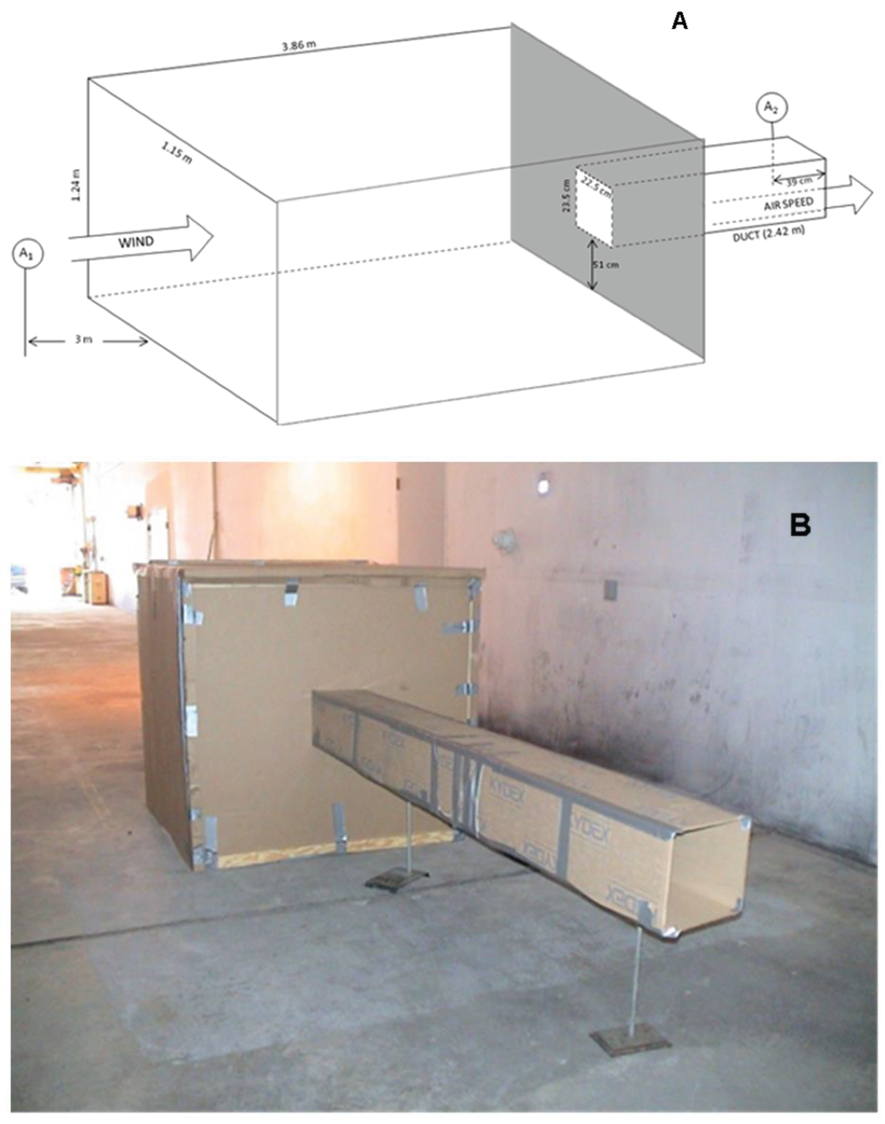
2 in section. Electric fans at the end of the tunnel moved air at controlled speeds from 0 up to 10 km/h (3 m/s). An approximate experimental model of the corridor and duct was built with 4.6 mm (3/16 inch) thick cardboard and assembled with high strength aluminum tape (
Figure 5). The model consisted of a main chamber 1.24 m high by 1.15 m wide, whose length could be altered to be either 1.2 m or 3.9 m long, and from the back of which air exited through a duct 0.23 m wide x 0.23 m high x 2.42 m long. Two anemometers, one located 3 m leeward of the main opening (Digital Model 840030, Sper Scientific, Scottsdale, AZ) and another (Cold Probe Veloci Calc, model 8346, TSI USA, St. Paul, MN) placed 39 cm from the end of the duct, measured wind speed and airflow simultaneously to one decimal point. In addition, a digital manometer monitored pressure within the main chamber (Model HD 700, Extech Inst., Nashua, NH) 0.47 m from the duct opening in the back wall.
Computational Fluid Dynamics
To estimate the effect of wind on the pyramid complex, computational fluid dynamics modeling was done with CFX, a software for Process and Product Design Optimization (ANSYS, Canonsburg, PA). CFX is a highly parallelized, general purpose fluid dynamics program with an adaptive architecture solver that enables calculating virtually any type of phenomena related to fluid flow. CFX software runs in a fully parametric environment coupled to an algebraic multigrid that uses second order numerics (by default) to ensure the most accurate predictions possible. The multi-grid mesh was refined with a minimum cell size of 0.0021 m, maximum cell face size of 7.0 m, and a maximum cell size of 14.0 m. The other parameters employed were the defaults. Inflation was imposed on the tunnel and ventilation duct in order to properly model boundary layer effects. Five inflation layers were used with a 0.272 transition ratio into the main mesh, which ensured the entirety of the mesh was of acceptable orthogonal quality (acceptable orthogonal quality was defined as a minimum orthogonal value above 0.05, as per ANSYS standard practice).
Results
Calculation of Airflow in the Duct by a Web-based Ventilation Calculator
To delineate the magnitude of the air flowing from the tunnel into the duct, an online ventilation calculator widely used to estimate wind loads on buildings was first used with the assumptions and parameters indicated in the previous section. In order to input data in the web-based ventilation calculator, we considered the corridor as an opening at the windward side of the building and the opening at the firepit (and surrounding galleries depicted in the photograph of
Figure 2A) as the exhaust side of structure.
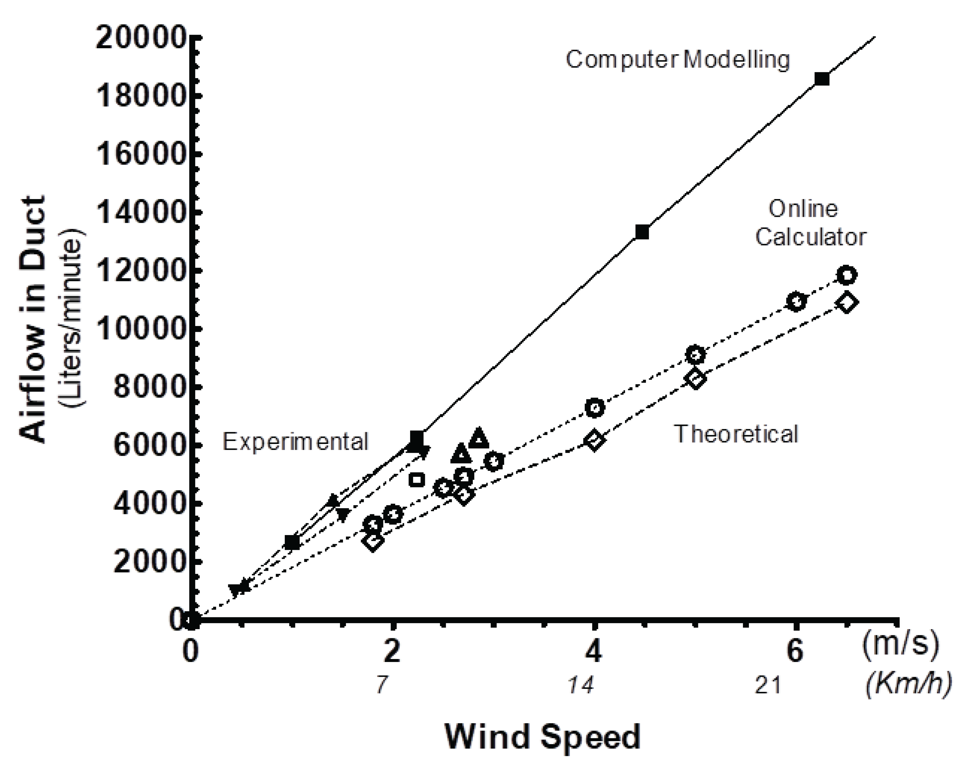
The air after exiting the duct into the fire pit would then flow into the atmosphere. The airflow (as total ventilation rate) exiting the under-floor duct when the corridor faced wind speeds of between 1.8 m/s and 6.5 m/s (6.5-23 km/h, corresponding to a light to fresh breeze in the Beaufort Scale), is represented in the graph of
Figure 3. Within the range studied, the relationship between the wind speed facing the corridor and the airflow exiting the duct into the fire pit resulted relatively linear. These values provided a first approximation to the magnitude of expected airflow. Uncertainty remained due to using an online ventilation calculator whose presumed purpose assumes a tall, prismatic building with vertical walls instead of an actual complex on top of a pyramid. This prompted more specific theoretical calculations of the airflow in the duct.
Theoretical Airflow Calculations.
The airflow measured in the
fogón ventilation complex, consisting of the corridor with antechamber and a duct beginning at the back wall of said antechamber and ending at the fire pit, was first considered without accounting for frictional losses in the walls. For calculations, the actual geometry of the complex shown in
Figure 2 was simplified to a configuration consisting of a large prismatic corridor ending in a wall with an opening from which exits the exhaust vent (of the type shown in
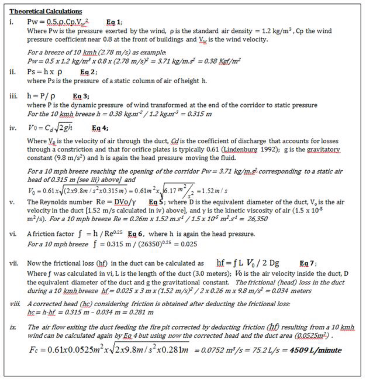
Figure 5A). Wind impacted the entrance of the corridor driving the air flow into the antechamber and then through the under-floor duct. This then vented into the fire pit. Therefore, the complex was naturally ventilated. The air-flow through the corridor and the duct was driven by the difference in wind pressure at the entrance of the corridor and that of the air flowing into the fire pit. This pressure difference was calculated by assuming that the wind energy is converted to a stagnation pressure along the corridor and that the pressure at the duct exhaust remains at atmospheric pressure. Therefore, the pressure at the entrance of the corridor is the atmospheric pressure plus the wind dynamic pressure, while the pressure at the exhaust duct is simply the atmospheric pressure.
The available wind energy appearing as dynamic wind pressure, which corresponds to the height of a static column of air exerting an equivalent pressure that is transformed at the end of the corridor to static pressure, is represented in
Figure 4 by Equations 1,2, and 3, respectively.
The L shape and relatively large volume of the corridor and antechamber relative to the duct would buffer the normal fluctuation in wind speed at the face of the corridor. The misalignment of the duct with the main axis of the corridor prevents direct impingement of the wind on the duct opening. This reduces the effect of wind fluctuation at the duct while still maintaining maximal wind pressure in the corridor. Furthermore, the corridor/antechamber system provides a relatively large reservoir of air pressurized by wind that is nearly stagnant and at a relative constant pressure. This results in a concomitant steady airflow through the small duct. Therefore, considering that the volumes of the corridor and antechamber are much larger than that of the duct, the velocity of air exiting through the duct can be calculated as the discharge of fluid through an orifice in a tank (Lindeburg 1992). The flow of air through the orifice was calculated by Torricelli’s Speed of Efflux equation corrected for the orifice geometry. The frictional losses of air in the corridor were disregarded since the boundary layer is very small compared to the area and because the air velocity (particularly near the end wall) is nearly zero. The frictional loss (hf) in the duct was then calculated by the Darcy-Weisbach Equation (Eq. 7 in
Figure 4) (Lineburg 1992). The airflow was calculated by Eq 4 again but now using a corrected head (hc) after deducting the frictional loss. The result for a 10 km/h breeze impacting the corridor is presented (
in italics) as an example in
Figure 4 with airflows for additional wind speeds plotted in
Figure 3.
Actual Measures of a Simplified Model within a Wind Tunnel.
To confirm or refine the calculations obtained by the methodology described above, we constructed a simplified model of the
fogón (schematized in
Figure 5A) and then introduced it to a wind tunnel as shown in
Figure 5B. The model consisted of a main chamber (1.2 m x 1.2 m x 0.9 m) which simulated the original corridor. A duct at the back of the corridor (0.23m x 0.23 m x 2 m) provided an exit for the air. Although the dimensions of the model were not precisely those of the structures at Caral, we considered that the construct could provide experience and experimental data that should approximate the airflow in the actual
fogón. The wind tunnel generated wind speeds of between 0 and 3 m/s (0-11 km/h) and anemometers (and pressure sensors) were located in the tunnel as indicated in
Figure 5A,B. Flow rates in the duct ranged from 4,360 to 6,270 liters per minute for wind speeds from 2.2 to 2.85 m/s. An extended range of wind speeds was tested with a longer simulated corridor (3.9 m long) with the flow rates measured for various wind speeds represented in
Figure 3. In addition, testing was done with and without a step (approximately 50.0 cm. x 28.0 cm x 26.6 cm) under the duct entrance in the simulated corridor. Shortening the corridor from 3.9 m to 1.2 m reduced airflow in the duct by 22 percent, 14 percent and 5 percent at wind speeds of 0.5 m/s, 1.45 m/s and 2.2 m/s, respectively (data not shown). The step did not alter the airflow rate but a flow-tuft made of light cloth tape placed over the step closely followed airflow changes at the entrance of the duct.
Figure 5.
Hard model testing within the wind tunnel. Panel A depicts a schematic representation of the constructed model showing its dimensions. A1 and A2 represent the locations of anemometer probes inserted in the air path to measure air velocity. Panel B shows a view of the model inside the wind tunnel with the duct protruding from the back wall. .
Estimates made with the online calculator, with calculations based upon theoretical principles, and experimental measurements in the breeze tunnel provided flow rates of air exiting the duct at given wind speeds. All these however, excluded the effects of elevation resulting from the ventilation system being placed on top of the pyramid, as well as any aerodynamic effects relating to such a massive structure.
Effect of Elevating the Fogón Mayor Above Surrounding Ground.
The orientation and location of the
fogón and its ventilation system on top of
Pirámide Mayor exposed the entrance of the corridor to increased wind speed.
The variation of wind speed and resulting available Aeolic power as a function of elevation atop thin masts has been previously reported (as indicated in a previous section). We employed these previously established graphs and equations relating the wind speed at ground level and its increase at various heights to calculate the increase along the elevation profile of Pirámide Mayor. The graphs presented in Figure 6 show that elevating the fogón 18 m above the ground level of the plaza increased the wind speed at the entrance of the corridor by nearly 50 percent.
The gain derived from previous measures of wind speed at different heights using relatively narrow and aerodynamically transparent masts or towers, although significant, is likely an underestimation. The effects of this massive pyramid on contemporary winds should have increased the already substantial airflow calculated here based on narrow masts, thus prompting the more accurate approach that follows.
Validation of Computer Simulation
First, we employed the computational fluid dynamics modeling program described earlier in this manuscript with the geometry and dimensions (shown in
Figure 5A) that were tested experimentally in the breeze tunnel. These initial simulations were completed to determine whether default parameters in the program would mimic the air flows obtained by experimental data obtained in the breeze tunnel. During these comparative studies we learned that the most relevant simulation parameter was the value of the frictional boundary layer imposed to the corridor and duct surfaces. The frictional boundary layer parameter that better resembled experimental data obtained in the breeze tunnel online included a 0.272 mesh transition ratio applied in 5 mesh layers. Modeling the effect of a 2.2 m/s (8 km/h) wind acting over a (1.7 m high x 1.7 m wide x 7 m long) corridor, we obtained results of 4,830 l/m airflow in the (0,20 m x 0.25 m x 3 m) duct. We determined that the airflows on similar models (wind facing a main chamber with a duct exiting from the back wall) obtained by advanced computer modeling (4,830 l/m) were within 2 percent of the experimental data measured inside the wind tunnel (4,734 l/m by extrapolating 2.67 m/s data to 2.2 m/s). In addition, computer simulation and experimental data were within 18 percent of online calculations (4,000 l/m) and 7 percent of estimates made using physical equations (4,509 l/m). Thus, the parameters used in computer simulation represented the ventilation system and resulting airflows within reasonable agreement with other approaches. The parameters that provided better agreement with experimental data obtained in the wind tunnel and therefore, the most accurate predictions of air flow were used in all subsequent modeling.
Computer Simulation of Air Flow on Top of the Pyramid
Considered is a pyramidal structure 18-19 m high, 140-150 m wide at the base, and 55 m wide at its top as illustrated in Figure 1 and
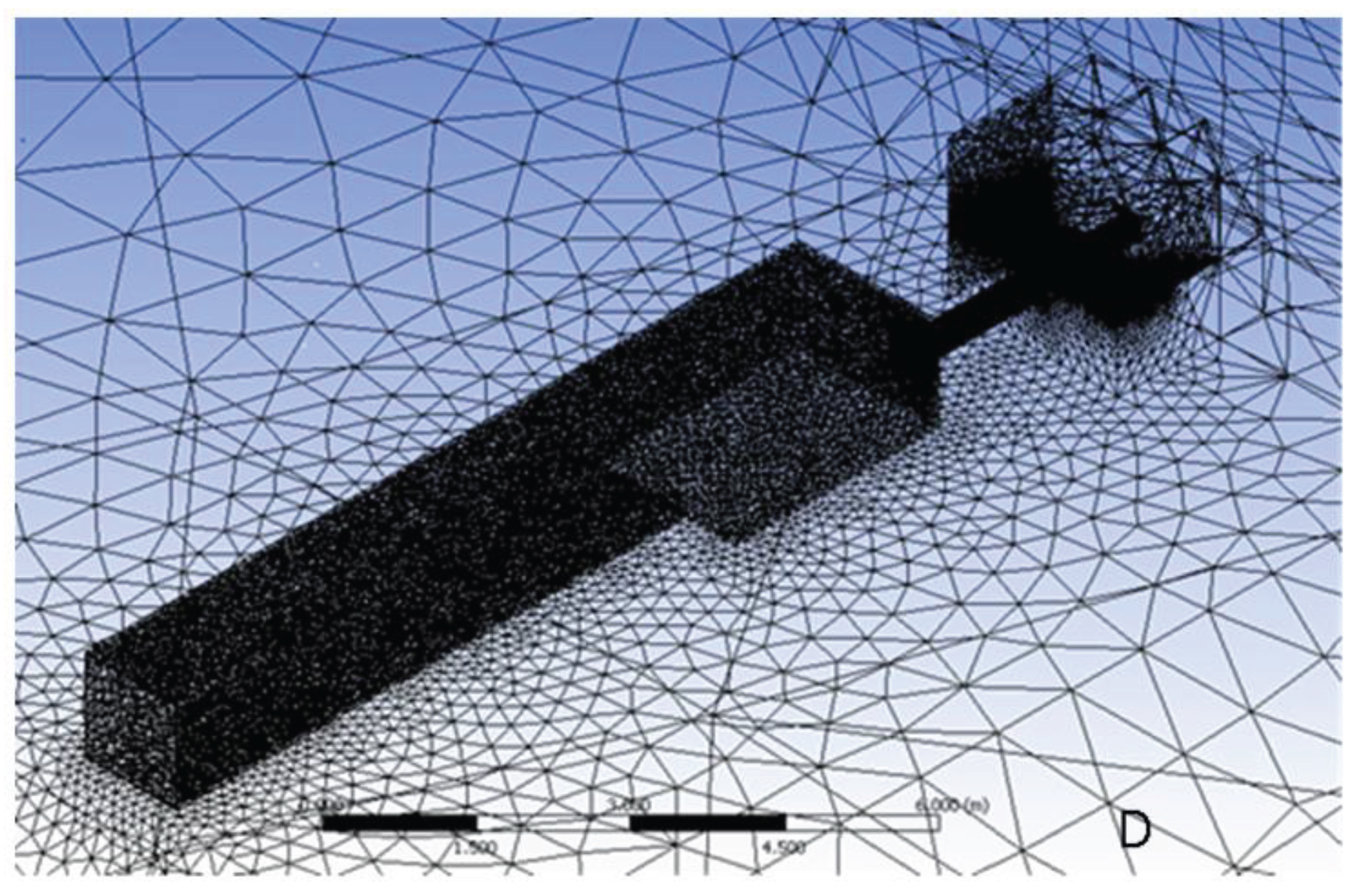
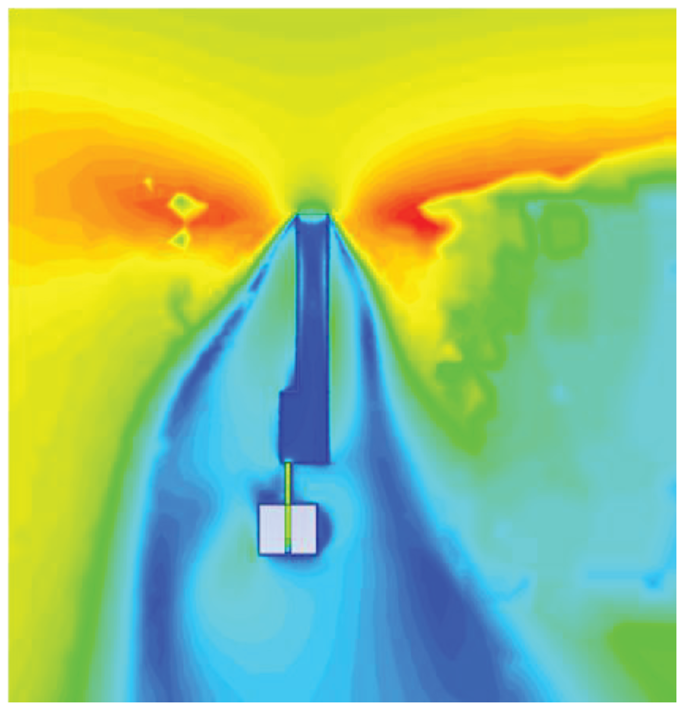
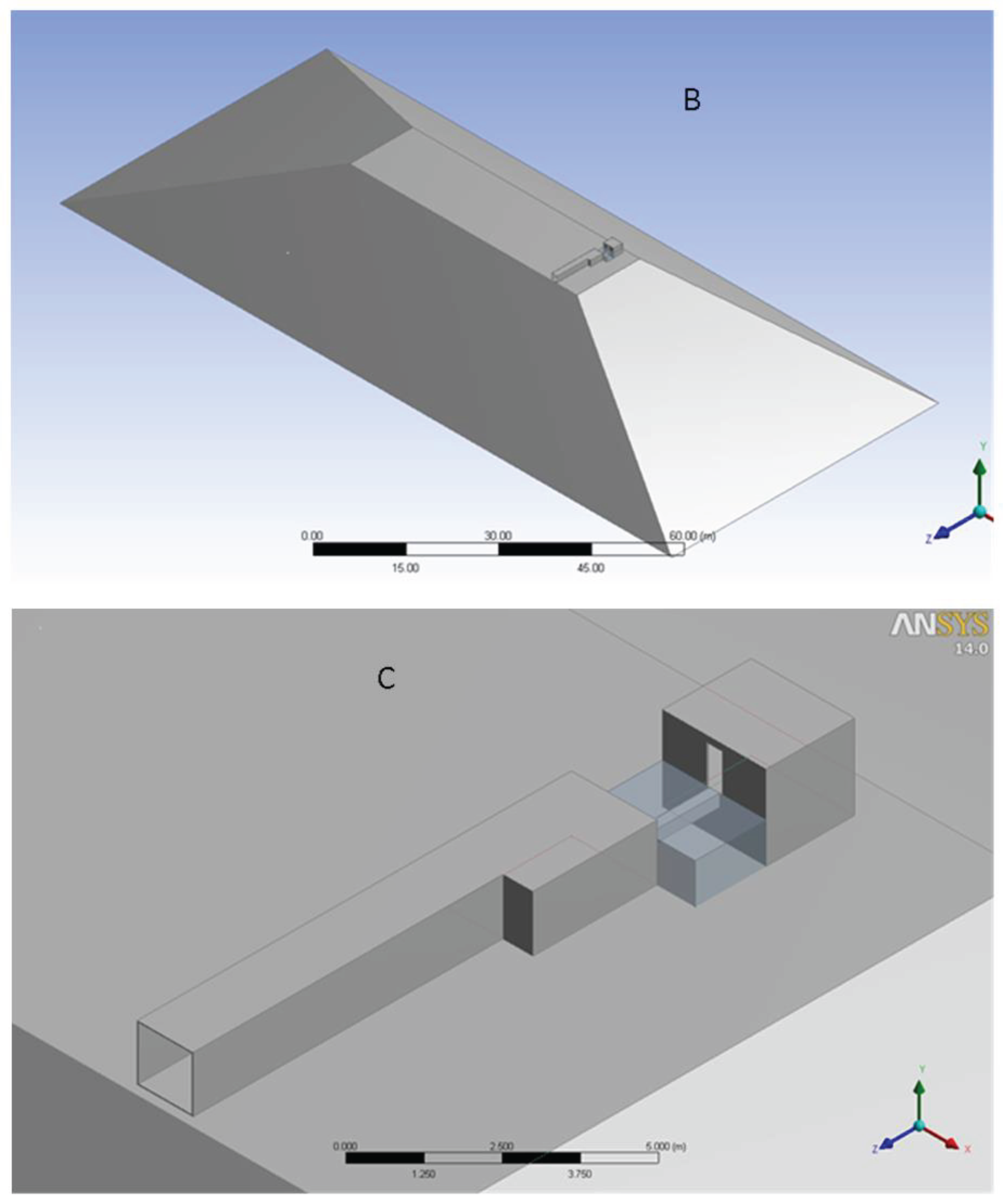
Figure 2. The complex consists of a corridor with antechamber and a step in Figure 7A and is represented by the models in Figure 7B,C, with the corresponding mesh map presented in Figure 7D. Computer calculation of the ventilation through the model resulted in the airflow contours of the type presented in
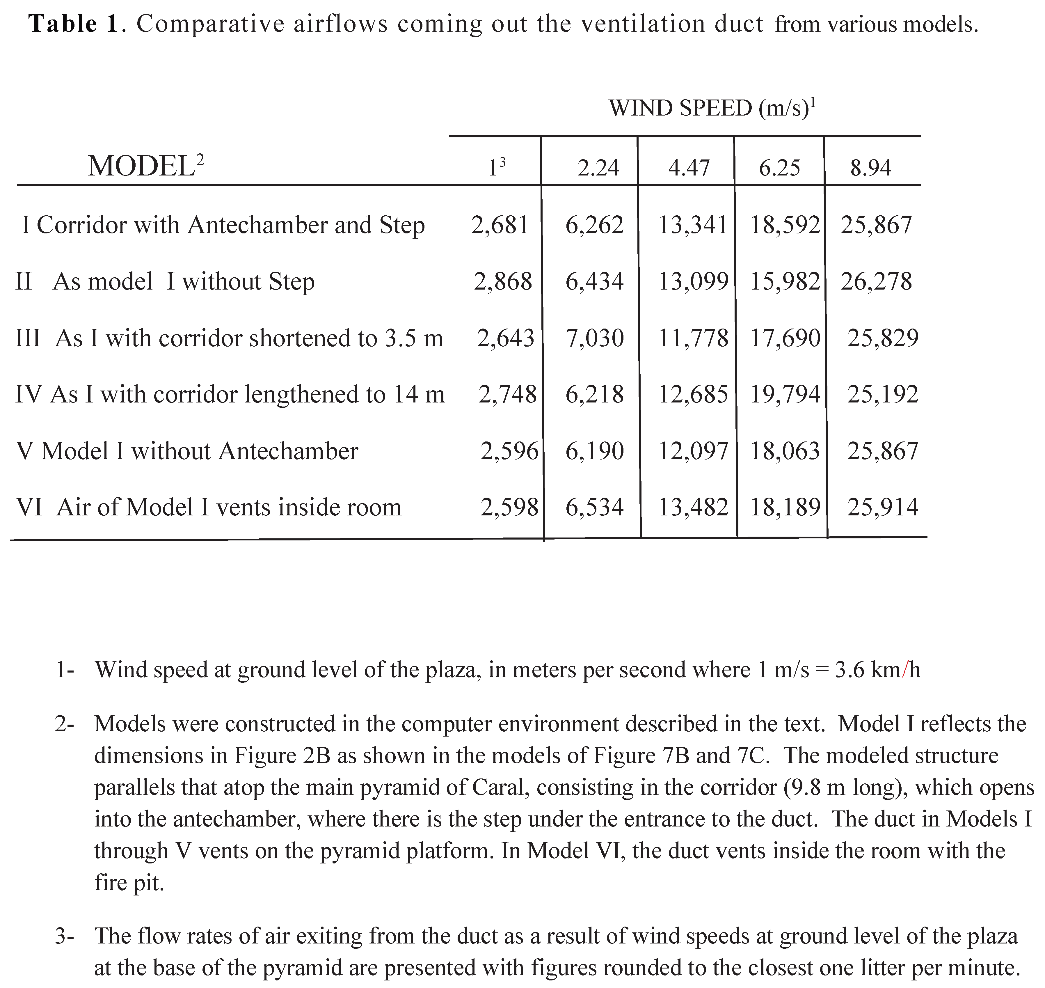
Figure 8. The comparison of all results calculated at various wind speeds showed that the computer simulation of models that included both the height and mass of the pyramid resulted in the largest air flows into the duct that feeds the fire pit (
Figure 3). Since the regression lines of airflow as a function of wind speed were nearly parallel to each other, the increase of airflow as modeled on top of the pyramid could be calculated to be approximately 70 percent greater than the airflows estimated by an online calculator or theoretical equations, both applied to wind speeds at ground level. In addition, and to uncover any effect of particular design characteristics in the construct, we altered the model by changing the length of the main corridor (lengthened to 14 m or shortened to 3.5 m).
Figure 7.
Aerodynamic Modeling. The figures depict the modeling and simulation process, with the photograph in Panel A presenting a perspective view of the ventilation system of the fogón with features labeled as in Figure 1 and
Figure 2. A computer model of the fogón complex atop the pyramid is presented in panel B with a close up in Panel C. Mesh features in panel D were calculated as described in the text corresponding to Model VI of Table 1.
We also separately removed both the antechamber and the step with the resulting airflow presented in Table 1. Shortening the corridor reduced the airflow in the duct by 12 percent and lengthening the corridor reduced the airflow by 5 percent for a surface wind of 4.5 m/s (20 km/h). Removing the antechamber reduced the airflow in the duct by 9 percent for a surface wind of 4.5 m/s (20 km/h). Lowering the wind speed resulted in smaller differences when varying the corridor length or excluding the antechamber. Including or removing the step under the duct entrance resulted in airflow variations smaller than 3 percent at all wind speeds studied.
Discussion
The long corridor facing SSW from which the underfloor duct reaches the fire pit had previously been considered as a deposit or a walkway. The calculated airflows and the cold that we experienced during breeze tunnel experiments even while wearing military-issue parkas indicate that using the corridor as a walkway during even a light breeze would be a rather uncomfortable experience. Use of this corridor as a deposit also seems unlikely considering that there is a relatively limited area on top of the pyramid. This suggests better use than storage for this premium real estate.
Figure 8.
Top view results of a simulation experiment. An illustrative example is presented in which wind at ground level was 10 km/h. The air speed contours on the upper part of the figure demonstrate the effect of the pyramid slope on the increase of the air flowing through the duct (lighter and darker shades correspond to faster and slower air speeds, respectively).
By contrast, the importance of the corridor is highlighted when considering that air (oxygen) would have been the most important variable to affect the performance of the connected Fogón Mayor, since wood or another cellulose-based substance was likely the fuel available to the Caral society.
Based on early Spanish accounts of Inca rituals (all several thousand years after Caral’s abandonment [Jones 2008]), the step at the end of the corridor has been suggested to play a ceremonial role as a support for offerings. Our findings suggest that using the step to deposit offerings is very unlikely because anything there would be immediately drawn into the under-floor duct, eventually blocking this passage. Our study did not identify any aerodynamic effect of the step. Rather serendipitously, however, we observed during experiments with the wind tunnel that the step would be an ideal location for any light material (cloth, long leaves, etc.) to be used to visually monitor the intensity of air-current flowing into the duct (a wind telltale).
The airflows resulting from a 2.2 m/s wind at ground level on a simplified design (representing a corridor and connected intake duct) estimated by three independent approaches or by experimental testing in the wind tunnel resulted in airflows exiting the duct that agreed within 2 to 18 percent from each other. This variation appears acceptable given the considerable differences among the various approaches employed and dimensional uncertainties due to recorded earthquakes and deteriorating of the structure through millennia.
Experimental testing supported by computer modeling suggests that the length of the corridor may have been optimized for airflow into the duct. We found that a duct of shorter length would result in a lower airflow due to a shorter column of wind being harnessed while a longer corridor also had a decreased airflow due to excessive friction.
Elevating the Fogón Mayor above the plaza appears as another technical decision to harness wind. Previous measurements of windmills atop masts or slim towers indicated that elevating the ventilation system for the Fogón Mayor 18 m resulted in nearly 50 percent gain in wind speed over that at the ground level of the plaza. However, the engineers at Caral did not appear content with only elevating the fogón in a small, narrow and relatively economic to build tower-like structure (feasible considering the bundled- rock construction practiced in many walls of Caral). Instead, the engineers placed the fogón complex at the top of a broad and sloped pyramid that further directed wind into the corridor. Our computer analysis demonstrates that building the fogón on top of a pyramidal structure of the size of the Pirámide Mayor increased available wind even more than could be expected from elevation alone (as predicted by calculations of wind shear in masts or towers). Results from computer modeling demonstrated an aerodynamic gain in airflow when the ventilation system was atop the pyramidal structure, with an airflow exiting the duct nearly 70 percent greater than that calculated at ground level by different approaches (see above). Further gain could result from having located Pirámide Mayor at the edge of a natural terrace, which stands 10 m above the river valley. This may have increased the draft in the leeward face, but this question is being left for future geographical and paleo-meteorological modeling that is outside the scope of the present work.
We realize that even higher altitude could have been gained more cheaply by placing the fogón on one of the mountains surrounding Caral (see Figure 1A). However, lower than expected wind speed at the corridor entrance may have occurred. The physical mass of the mountain may have prevented the fogón from taking full advantage of any negative back pressure that would normally develop on the leeward side. Moreover, the mountains surrounding Caral are devoid of almost all vegetation and all firewood for the fogón would have to have been carried to the top of the mountain. This scarcity of fuel at the top of a mountain would rapidly have become a larger limiting factor in fire making compared to the relatively lower wind speeds but proximity of fuel at the top of a pyramid in the valley. Therefore, intaking air on top of a pyramid built over relatively flat land and near the fuel of the river valley was the best solution for the Fogón Mayor of Caral.
Careful design and laborious construction indicate that the
Fogón Mayor was intended to operate with copious amounts of air/oxygen. In fact, the engineers operating the
Fogón Mayor must have contended with two main consequences of increasing wind speeds (our calculations indicate that the ventilation complex was designed to operate efficiently with winds at ground level from 4-6 km/h up to 25-30 km/h, corresponding from light air to moderate gale, respectively). A main consequence of wind speed relates to efficiency and the need to keep the airflow from the duct in a narrow range. Burning of any fuel (here most likely wood or any other cellulose-based material) depends on oxygen (air) flow in a rather exquisite balance. A relatively low airflow starves any fire. Heat and fuel are then lost in smoke. An excessive airflow will cool the fire, robbing it of heat which is then wasted in the exhaust. The second consequence of regulating the wind relates to the very survival of the structural integrity of the
fogón. Excessive airflow could simply have blown the roof off of the building. The wind pressure inside the corridor suggests that the archaic engineers must have been able to operate the ventilation system to tolerances quite close to catastrophe. Caral engineers solved the need for a delicate balance between variable outside winds and air flowing into the fire pit by locating doors at the end of the air intake corridor (
Figure 2). These doors (that open toward the airflow and would tend to be closed by wind pressure) allowed airflow to be regulated in the duct by relieving wind pressure in the corridor. They also served as a safety device to rapidly vent excess wind pressure before the roof would blew off.
It was previously reported that approximately 5,800 years ago, the return of El Niño (the warm phase of the El Niño–Southern Oscillation phenomenon, or ENSO) after a hiatus of several millennia (Sandweiss et al. 1996; Sandweiss et al. 2009) coincided with emplacement of a fishery dominated by small schooling fish and of a contemporary coastal regime dominated by strong daily winds blowing inland north-northeast off the ocean (Andrus et al. 2002; Reitz 2008). The corridor of the Fogón Mayor faced south-south west and ran north northeast and thus, it was accurately oriented (within the 22.5 degree resolution of the 16 point compass) to receive the prevailing winds of the time. Any deviation would have reduced the wind power as a function of sine of the angle between the corridor and wind. Thus, a one-compass-point [22.5 degrees] misalignment would have resulted in 38 percent loss in wind power. The probability that Pirámide Mayor was aligned to prevailing wind only by chance is relatively low (one orientation point out of 16 possible compass orientations, resulting in 1/16 or .06 probability that alignment with prevailing winds was just by chance). In contrast, the precise alignment of the corridor with contemporary prevailing winds suggests that harnessing wind as needed in the fogón was a major consideration to the pyramid builders.
All the approaches that were used in the present study agree in that the architectural design of the
Fogón Mayor complex would provide large quantities of air (oxygen) to the fire pit, resulting in temperatures and other operational conditions to be presented in a companion study regarding combustion. The most refined of our calculations included computer modeling utilizing parameters that resulted in airflows within 2 percent accuracy (as compared to experimental data in the breeze tunnel). This approach when applied to the
fogón as part of the whole pyramid indicated that the complex was designed to harness light to moderate winds to deliver 3,000 to 18,000 liters of air per minute into the fire pit (
Figure 3). This considerably large airflow in
Fogón Mayor was attained without workers directly blowing into the fire and instead, it was achieved solely by the aerodynamic design of a structure built sometime during the third millennium B.C. Although harnessing wind is not unique to Caral, this degree of technological sophistication seems to have vanished in many later societies in South America, Mesoamerica, Egypt, and other parts of the ancient world (Nordenskiold 1921; Garland and Bannister 1927; Bray 1985, Shimada and Merkel 1991) where air for combustion was continuously and laboriously insufflated by workers through blowpipes or tuyeres.
The findings of the present study suggest that a complex construction, able to deliver the considerable airflows reported here, was within the reach of an archaic society in coastal ancient Peru. We hope the analysis presented in this work will raise also questions about the technological potential of ventilation systems reported at archaeological sites of other cultures.
Conclusions
Every approach employed in this study demonstrated that the corridor with antechamber and duct atop the largest pyramid in Caral was a sophisticated ventilation system where the prevailing wind was able to provide between 3,000 and 18,000 liters of air per minute to the attached fogón. This ventilation system could be regulated (by doors in the antechamber) to respond to changes in wind speed to maintain the air flowing to the fire pit. This control maintained burning efficiency and building safety. Considering the calculated increase in airflow resulting by elevating the complex atop a massive sloping structure, we must conclude that ventilating the fogón must have been a major consideration in determining the construction of a pyramidal shape, locating the structure at the edge of a terrace, and orientating this largest pyramid in Caral towards the contemporary prevailing winds. These aerodynamic findings together with the study in a companion article of the combustion temperatures that this airflow enabled, suggest an advanced technological knowledge in an archaic American society with a degree of sophistication rarely contemplated by the archaeological community.
Acknowledgements
We acknowledge Dr. Ruth Shady for directing the pioneering archaeological work that uncovered the subject of our study. We also deeply appreciate her generous invitation to visit Caral in 2012 to begin our investigations. We are grateful also to Marcos Machacuy, Carlos Leyva and Pedro Novoa for generously supplying publications that the professional team at Caral had previously produced. We thank Marcelino Valderrama for his continued interest in the project and for his assistance in facilitating communications between South and North America.
References
- Andrus, C.F.T., D.E. Crowe. Otolith a18O record of Mid-Holocene sea surface temperatures in Peru. Science 2002, 295, 1508. [Google Scholar] [CrossRef] [PubMed]
- Bray, Warwick. Ancient American metallurgy: five hundred years of study. pp 76-84 In The art of pre-Columbian gold. The Jan Mitchell Collection. Metropolitan Museum of Art Press, New York. 1985. [Google Scholar]
- Garland, H.; Bannister, C.O. Ancient Egyptian Metallurgy. Charles Griffin & Company. 1927. [Google Scholar]
- Holmes, J.D. 1986. Wind Loads on Low-Rise Buildings: The structural and environmental effects of wind on buildings and structures. Monash University Press, Melbourne, Australia.
- Jones, D. M. 2008. The Myths and Religion of the Incas. Anness Publishing. London.
- Lindeburg, M.R. Engineer in Training Reference Manual 8th Ed. Professional Publications, Belmont CA. 1992. [Google Scholar]
- 7. Nordenskiold, E. 1921. The Copper and Bronze Ages of South America. Comparative Ethnographical Studies 4, Goteborg, Germany.
- 8. Reitz E.J., C.F.T. Andrus, and D.H. Sandweiss.
- 2008. In Human Impacts on Marine Environments, eds Rick T, Erlandson J., Univ of California Press, Berkeley, pp 125–145.
- Sagripanti J-L, D. Wise, R.A. Anthenien Jr., E. Yoon, C. Kleihege.
- 2018. High Energy Generation and Elevated Temperature Potential of an Archaic Furnace in Ancient Peru. Platform presentation. The 82nd Annual Meeting of the Society for American Archaeology, Washington, DC. 2018 (tDAR id: 443107).
- Sandweiss Daniel H., J. B. Richardson; Reitz, E.J.; Rollins, H.B.; Maasch, K.A. Geoarchaeological evidence from Peru for a 5000 years B.P. onset of El Niño. Science 1996, 273, 1531–1533. [Google Scholar] [CrossRef]
- Sandweiss, D.H., R.S. Shady, M.E. Moseley, D.K. Keefer, and C.R. Ortloff. 2009. Environmental change and economic development in coast al Peru between 5800 and 3600 years ago. Proc. Nat. Acad. Sci. 106 (5) ; 1359 - 1363.
- Shady, R.S. 2006. America’s first cit y? The case of late archaic Caral. In Andean Archaeology III North and South. W. Isbell and H. Silverman (Eds) Springer, Berlin.
- Shady, R.S. 2009. Caral-Supe y su Entorno natural y Social en los Orígenes de la Civilización. In: Andean Civilization, a Tribute to Michael E. Moseley. UCLA Contsen Press. Los Ángeles.
- Shady, R.S. and M. Machacuy. 2000. El Altar del Fuego Sagrado del Templo Mayor de la Ciudad Sagrada de Caral.
-
Boletín Museo Arqueología y Antropología Universidad Mayor de San Marcos/Perú 3 (12) 1-7.
- Shady R.S. and C. Kleihege. 2008. Caral: The First Civilization in the Americas. Universidad de San Martín de Porres Press.
- Shady R.S, J. Haas; Creamer, W. Dating Caral, a Preceramic site in the Supe Valley on the central coast of Peru. Science 2001, 292, 723–726. [Google Scholar]
- Shimada, I., and J.F. Merkel 1991. Copper alloy metallurgy in ancient Peru. Scientific American. July, 80-86.
|
Disclaimer/Publisher’s Note: The statements, opinions and data contained in all publications are solely those of the individual author(s) and contributor(s) and not of MDPI and/or the editor(s). MDPI and/or the editor(s) disclaim responsibility for any injury to people or property resulting from any ideas, methods, instructions or products referred to in the content. |
© 2024 by the authors. Licensee MDPI, Basel, Switzerland. This article is an open access article distributed under the terms and conditions of the Creative Commons Attribution (CC BY) license (http://creativecommons.org/licenses/by/4.0/).
