Preprint
Article

Stress Wave Propagation in a Rayleigh–Love Rod with a Sudden Cross-Sectional Area Variation Impacted by a Striker Rod

Altmetrics

Downloads

82

Views

89

Comments

0

A peer-reviewed article of this preprint also exists.

This version is not peer-reviewed

Submitted:

18 March 2024

Posted:

20 March 2024

You are already at the latest version

Alerts
Abstract
This paper presents an in-depth study of the stress wave behavior propagating in a Rayleigh–Love rod with a sudden cross-sectional area change. The analytical solutions of stress waves are derived for the reflection and transmission propagation behavior at the interface of the cross-sectional area change in the rod, considering inertia and Poisson’s effects. Examples solved by the finite element method are provided to verify the correctness of the analytical results. In addition to the forward analysis of Rayleigh–Love wave propagation in rods impacted by a striker rod, a nondestructive testing method is proposed to conduct the defect assessment in the rod type of the structure component with a sudden cross-sectional area change within a cover medium by using the measured signals at the measurable zone of the rod to be inspected.
Keywords: 
Subject: Engineering  -   Civil Engineering

1. Introduction

Stress wave propagation, particularly concerning the nondestructive testing (NDT) of structures, is an important field in engineering. The NDT method is crucial for assessing the safety, reliability, and efficiency of structures [1,2,3,4,5] because it allows for the evaluation of structures and component integrity without causing damage. This approach is particularly vital for detecting defects or fractures in engineering structures [6,7,8,9,10]. It is also used for structural analysis and optimization to enhance the bearing capacity of a structure [11,12]. The detection of the damage condition in rod-type structure elements embedded inside the medium is an important topic in the NDT field. Among the various theories introduced to understand the longitudinal wave propagation for the impact echo NDT method, Rayleigh–Love rod theory [13] presents the closest modeling to the observed real behavior. This theory combines the effects of lateral inertia and Poisson’s ratio, often neglected in the traditional model of D’Alembert [14]. Incorporating lateral inertia and Poisson’s ratio is crucial for analyzing longitudinal stress wave propagation in rods because it considerably affects wave behavior, as evidenced by the research provided by Yang et al. [15,16].
The primary goal of this research is to develop an NDT method aimed at identifying the positions of cross-sectional area changes based on forward analysis of stress wave propagation in rod. Since the exhibiting abrupt changes in cross-sectional area of a rod often indicates damage or defects in the rod type structure member. The theoretical foundation of this research is grounded in Rayleigh–Love rod theory [13], which provides a comprehensive understanding of stress wave propagation in rod, particularly in the context of sudden cross-sectional changes. This complex theoretical approach enables a detailed analysis of the complex dynamics of wave propagation, including the critical effects of lateral inertia and Poisson’s ratio.
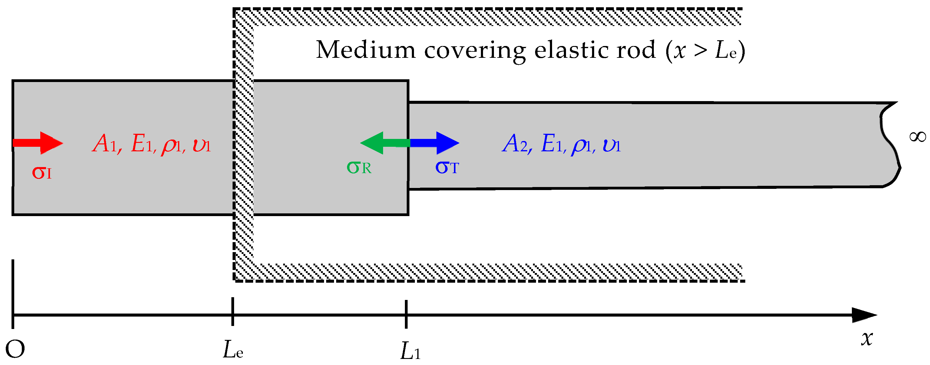
As depicted in Figure 1, the model for this research is developed to determine the changing cross section A2 and length L1 based on stress wave propagation signals. The analysis delves into the reflection and transmission of waves in rods undergoing sudden changes in their cross-sectional area. These changes may be regarded as the main defects, such as cracks, necking, and corrosion in the rod. This aspect is crucial because the shape and intensity of stress waves are significantly affected at the discontinuity interface within a structure [17,18]. Previous studies [17,18] have documented the substantial influence of boundaries on wave behavior, particularly noting how sudden changes in cross-sectional area can modify wave propagation. However, these studies do not fully consider the specific effects of lateral inertia and Poisson’s ratio on stress wave propagation.
This research seeks to enrich the understanding of stress wave propagation in structures with abrupt cross-sectional changes by investigating the interaction between wave behavior and discontinuous cross-section areas. Moreover, the practical application of this research involves the numerical verification of an impact echo testing method. The striker rod is moved with an impact velocity of 2v0. Then, an incident wave and a contingent reflection wave are generated at the position of a cross-sectional area change. A signal is measured at a sensing site for back-calculation to determine the position and severity of a cross-sectional area change. This study aspires to advance the theoretical knowledge in the field and contribute practically to the NDT of defect assessment in rods.

2. Fundamental Theory of Stress Wave Propagation in a Rayleigh–Love Rod

This section provides the fundamental theory of stress wave propagation in a Rayleigh–Love rod, followed by the derived solution for the stress wave propagation equation in a Rayleigh–Love rod with a sudden variation in cross-sectional area.

2.1. Fundamental of Rayleigh- Love Theory

The Materials and Methods should be described with sufficient details to allow others to replicate and build on the published results.
The behavior of stress waves in a material is typically described by the wave equation. It also captures the relationship between the displacement of particles within the material and the rate at which these displacements change over time and space. This dynamic phenomenon is often attributed to the transmission of energy and momentum through the medium. The traditional wave equation for one-dimensional wave propagation in a rod is given by [14]
2 u t 2 = c 0 2 2 u x 2 ,
where u (x, t) represents the axial (longitudinal) displacement of a point located at position x in the rod at time t, and c0 is the wave velocity without considering Poisson’s ratio effect. Herein, wave velocity is related to the mass density ρ and Young’s modulus E of the rod by using the equation c 0 = E / ρ .
Equation (1) provides a foundational understanding of wave propagation in rods. However, it does not fully reflect the wave behavior in rods as observed in the real world. Rayleigh and Love [13] recognized this limitation. They conducted a study that resulted in the development of a revised wave equation that is in keeping with the dynamics of wave propagation in rods. An important feature of this modified equation is the incorporation of Poisson’s effect, an aspect that clears light on the transversal deformations during the wave’s movement. The detailed derivation of the modified wave equation presented by Rayleigh and Love [13] is shown in Appendix A. This derivation incorporates Poisson’s effect and provides a generalized representation of the deformation process. Applying Hooke’s law to correlate lateral strain with longitudinal stress and assuming uniaxial stress can simplify the complex relationships in the rod’s deformation. Then, the derivation utilizes the energy method, calculating the kinetic and potential energy densities to elucidate the rod’s dynamics. This step involves integrating these energy expressions over the rod’s cross section, with a focus on longitudinal and lateral displacements. A balance is established between the internal and external forces acting on the rod by employing Hamilton’s principle. Finally, an equation is derived using the variational method, accurately describing the stress wave propagation in the rod as follows
2 u t 2 = c 0 2 2 u x 2 + υ 2 κ 2 4 u x 2 t 2 ,
where u is the axial displacement in the axial direction of stress wave propagation, υ is Poisson’s ratio, and κ is the radius of gyration of the cross section. Subject to the following boundary conditions, as shown in Eq. (A19) of Appendix A, the stress equation can be expressed as
σ = E u x + ρ υ 2 k 2 3 u x t 2 , at x = 0 and x = L .
Various methods, such as separation of variables [19,20,21], D’Alembert’s solution [22,23], finite difference method [24], finite element method (FEM) [25,26], or Laplace transform [27,28,29], can be employed to solve Eq. (2). The Laplace transform, a mathematical tool that transitions functions from the time domain to the s-domain, offers an elegant method for simplifying and solving differential equations [30]. When applied in wave propagation, this transform converts the original differential equation problem into an algebraic equation, making managing and solving easy. The solution is then converted back to the time domain using the inverse Laplace transform, which provides an accurate solution to the original wave propagation problem. Therefore, the Rayleigh–Love rod model, which considers the effects of lateral inertia, can be effectively solved with the Laplace transform. This analytical approach contributes to a detailed interpretation of the wave propagation dynamics and the consequential stress distribution, thereby providing substantial insights into the dynamic response of materials under stress wave propagation.

2.2. Solution of the Stress Wave Propagation Equation in a Rayleigh–Love Rod with a Sudden Cross-Sectional Area Variation

This research sets the approach based on the results of the Laplace transform method derived from Yang et al. [16], and the exact solution for the transmitted and reflected stress waves in a Rayleigh–Love rod with a sudden cross-sectional variation is derived. Subsequently, a backward analysis method can be developed to determine the position of the changing cross section and the ratio of the reduced area to the original area, as illustrated in Figure 1.
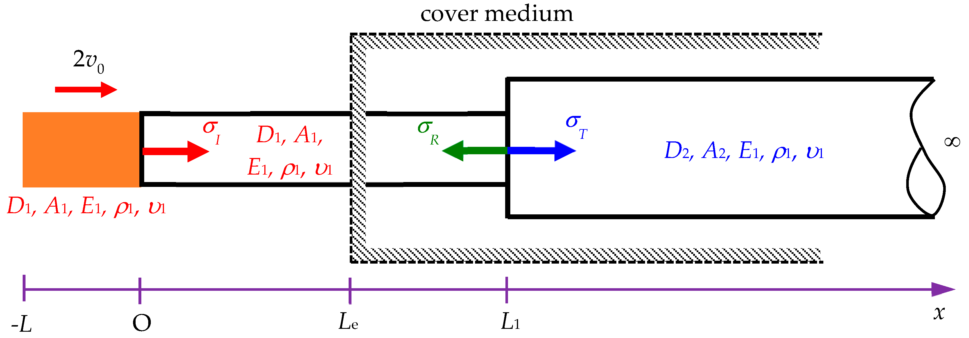
Yang et al. [16] focused on building an impact model based on split Hopkinson tests. The process begins with a semi-infinite rod, known as the incident bar, being struck longitudinally by a striker bar. The traditional one-dimensional theory suggests that the resulting impact generates a rectangular pulse if both rods are composed of the same material and have identical cross-sectional areas. However, the distortions of the pulses are expected on theoretical grounds and observed during experiments. Yang et al. [16] derived the analytical solutions for the longitudinal impact problems in dispersive rods. Their discussion focused on a situation where a semi-infinite Rayleigh–Love rod was impacted by a striker rod of length L with the same material and cross-sectional area as the Rayleigh–Love rod, as depicted in Figure 2.
At the initial time t = 0, a finite striker rod moving coaxially at an impact velocity of 2v0 hits a stationary semi-infinite rod, with both rods assumed to be unstressed. Consequently, the initial conditions relating to the axial displacement u can be expressed as follows:
u ( x , 0 ) = 0 , u ( x , 0 ) t = 2 v 0 , L x < 0 ,
u ( x , 0 ) = 0 , u ( x , 0 ) t = 0 , 0 x < .
The boundary conditions at the free end, where x = L , and at infinity are determined by
σ ( L , t ) = 0 , | u ( , t ) | = 0 .
If the two rods are tightly bonded without separation following the collision, then the coupled continuity conditions at the contact surface x = 0 can be established as
u ( 0 , t ) = u ( 0 + , t ) , σ ( 0 , t ) = σ ( 0 + , t ) .
Yang et al. [16] converted the values to dimensionless quantities for easy transformation by setting u ¯ = u D , x ¯ = x D , t ¯ = c t D , L ¯ = L D , b = ν κ ¯ = ν κ D , v ¯ 0 = v 0 c , and σ ¯ = σ E . The Laplace transform is employed to solve Eq. (2). The results in the s domain are obtained as follows:
{ d 2 U d x ¯ 2 s 2 1 + b 2 s 2 U = 2 v ¯ 0 1 + b 2 s 2 , L ¯ x ¯ < 0 d 2 U d x ¯ 2 s 2 1 + b 2 s 2 U = 0 , 0 x ¯ < ,
where U ( x ¯ , s ) = L { u ( x ¯ , t ¯ ) } is the displacement in the s domain.
Solving Eq. (8) with the boundary conditions can obtain the displacement function in the s domain as follows:
U ( x ¯ , s ) = { v ¯ 0 s 2 [ 2 e x ¯ s 1 + b 2 s 2 e x ¯ s 1 + b 2 s 2 ] , L ¯ x ¯ < 0 v ¯ 0 s 2 [ e x ¯ s 1 + b 2 s 2 e ( x ¯ + 2 L ¯ ) s 1 + b 2 s 2 ] , 0 x ¯ < .
Utilizing an inverse Laplace transformation in Eq. (9) obtains the result in a semi-infinite rod as
u ¯ ( x ¯ , t ¯ ) = 4 v ¯ 0 π 0 1 b sin L ¯ η 1 b 2 η 2 cos ( x ¯ + L ¯ ) η 1 b 2 η 2 sin ( t ¯ η ) 1 η 2 d η , 0 x ¯ < .
The stress formula in Eq. (3) in a semi-infinite rod is determined as
σ ¯ ( x ¯ , t ¯ ) = u ¯ x ¯ + b 2 3 u ¯ x ¯ t ¯ 2 .
From Eq. (10) and (11), Yang et al. [16] provided the results of stress wave propagation in the semi-infinite Rayleigh–Love rod as follows:
σ ¯ ( x ¯ , t ¯ ) = 4 v ¯ 0 π 0 1 b sin L ¯ η 1 b 2 η 2 sin ( x ¯ + L ¯ ) η 1 b 2 η 2 sin ( t ¯ η ) ( 1 b 2 η 2 η ) d η .
Equation (12) can efficiently present the stress wave propagation in the Rayleigh–Love rod model with a sudden cross-sectional variation, which is embedded inside a medium with x > Le. It cannot be identified from outside the structure, as depicted in Figure 3. Interactions occur at the interface when a wave motion encounters a discontinuity in a rod. The incident wave approaches the disruption, leading to reflected and transmitted waves. The distinctiveness of the Rayleigh–Love model lies in its acute focus on the effects of lateral inertia, providing deep insights into the dynamics of wave behavior at rod discontinuities. This model, illustrated in Figure 3, offers a comprehensive vision and theoretical representation of the problem to be investigated in this study. Converting the dimensionless quantities from Eq. (12) into dimensional quantities can simplify the analysis and obtain the following result:
σ I ( x , t ) = 4 ρ c v 0 π 0 1 b sin L η D 1 1 b 2 η 2 sin ( x + L ) η D 1 1 b 2 η 2 sin ( t c D 1 η ) ( 1 b 2 η 2 η ) d η ,
where b = υ κ ¯ , κ ¯ = κ D 1 , κ = I 1 A 1 , η is a variable in the contour integration of the Laplace inverse transform, ρ is the mass density, c is the longitudinal wave velocity of the elastic material, and v0 is the impact velocity.
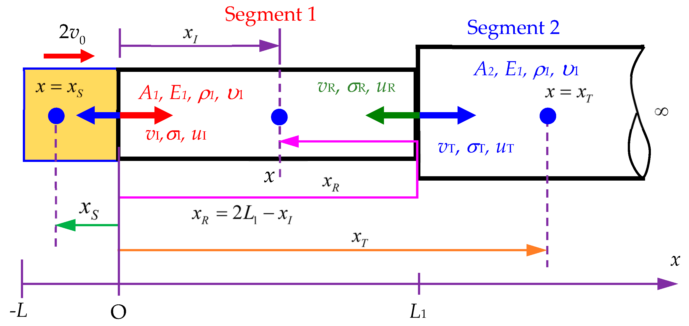
In this study, the incident stress result is considered to determine the reflected stress ( σ R ) and transmitted stress ( σ T ) in a Rayleigh–Love rod with a sudden change in cross-sectional area under the effects of Poisson’s ratio and lateral inertia. Based on the balance of forces at the interface between two segments, the total force applied by segment 1 (from the incident and reflected waves) must be equal to the total force applied by segment 2 (from the transmitted wave), as shown in Figure 4. Thus, the following equation is obtained:
A 1 ( σ I + σ R ) = A 2 σ T ,
where A1 and A2 are the cross-sectional areas of segment 1 and segment 2, respectively; σI, σR, and σT are the incident, reflected, and transmitted stresses, respectively.
Based on the continuity of velocity in Figure 4, the velocity of the interface between the two segments must be the same, which is expressed as
v I v R = v T .
The relationship between stress and velocity in the rod is shown as follows (Appendix B):
σ = ρ c v ,
where c is the longitudinal wave velocity of the elastic material, and v is the velocity of the material point under stress σ.
Based on Eq. (16), the velocity for incident, reflected, and transmitted waves can be, respectively, presented as
v I = σ I ρ 1 c 1 ,
v R = σ R ρ 1 c 1 ,
v T = σ T ρ 2 c 2 .
Substituting Eqs. (17) to (19) into Eq. (15) can obtain
σ I ρ 1 c 1 σ R ρ 1 c 1 = σ T ρ 2 c 2 .
Solving Eqs. (14) and (20) can obtain the reflected stress σ R and transmitted stress σ T as follows:
σ R = A 2 ρ 2 c 2 A 1 ρ 1 c 1 A 1 ρ 1 c 1 + A 2 ρ 2 c 2 σ I = R × σ I ,
σ T = 2 A 1 ρ 2 c 2 A 1 ρ 1 c 1 + A 2 ρ 2 c 2 σ I = T × σ I ,
where the reflected ratio is R = A 2 ρ 2 c 2 A 1 ρ 1 c 1 A 1 ρ 1 c 1 + A 2 ρ 2 c 2 , and the transmitted ratio is
T = 2 A 1 ρ 2 c 2 A 1 ρ 1 c 1 + A 2 ρ 2 c 2 .
According to Figure 3, the stress wave propagation σ1 traveling along segment 1 is determined as
σ 1 ( x , t ) = σ I ( x , t ) + σ R ( 2 L 1 x , t ) ,
where   σ I ( x , t ) = 4 ρ c v 0 π 0 1 b sin L η D 1 1 b 2 η 2 sin ( x + L ) η D 1 1 b 2 η 2 sin ( t c D 1 η ) ( 1 b 2 η 2 η ) d η ,
σ R ( 2 L 1 x , t ) = 4 ρ c v 0 R π 0 1 b sin L η D 1 1 b 2 η 2 sin ( 2 L 1 x + L ) η D 1 1 b 2 η 2 sin ( t c D 1 η ) ( 1 b 2 η 2 η ) d η ,
x [ 0 , L 1 ] , where x is the positions determined for the incident and reflected stresses (see Figure 4).
The propagation of the transmitted stress propagation σ2 traveling along segment 2 is determined as
σ 2 ( x , t ) = σ T = 4 ρ c v 0 T π 0 1 b sin L η D 1 1 b 2 η 2 sin ( x + L ) η D 1 1 b 2 η 2 sin ( t c D 1 η ) ( 1 b 2 η 2 η ) d η ,
x [ L 1 , ] , where x is the position determined for the transmitted stress.
The stress wave propagation in the striker rod is determined as follows:
σ S ( x , t ) = 4 ρ c v 0 π 0 1 b sin L η D 1 1 b 2 η 2 sin ( x + L ) η D 1 1 b 2 η 2 sin ( t c D 1 η ) ( 1 b 2 η 2 η ) d η , L x < 0 ,
x [ L , 0 ] , where x is the position for the determined stress wave in the striker rod.
When the Poisson’s ratio is set as zero, the incident stress, reflection stress, and transmitted stress are, respectively, expressed as follows:
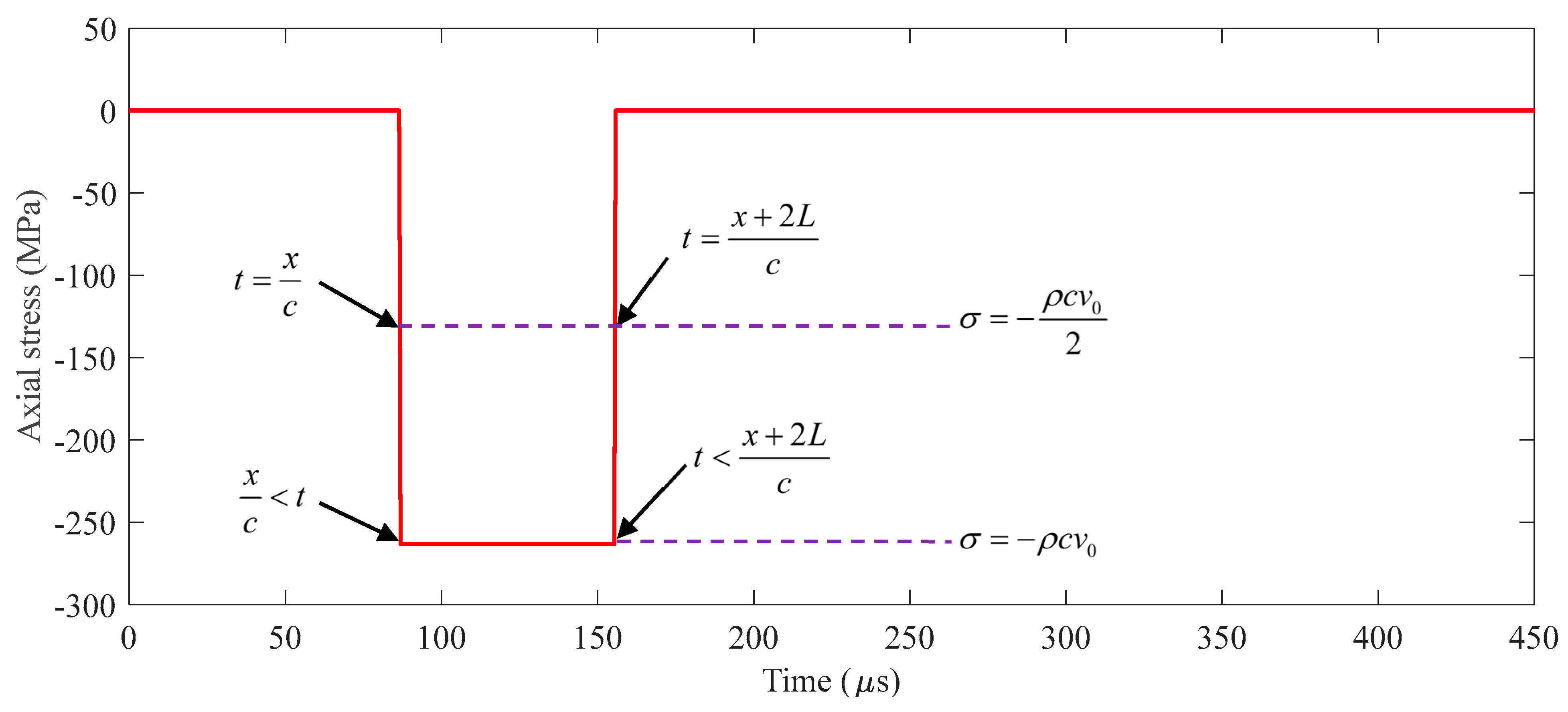
σ I ( x , t ) = 4 ρ c v 0 π 0 sin L η D 1 sin ( x + L ) η D 1 sin ( t c D 1 η ) ( 1 η ) d η = { ρ c v 0 , x c < t < x + 2 L c ρ c v 0 2 , 0 , t = x c , t = x + 2 L c otherwise ,
σ R ( 2 L 1 x , t ) = 4 ρ c v 0 R π 0 sin L η D 1 sin ( 2 L 1 x + L ) η D 1 sin ( t c D 1 η ) ( 1 η ) d η = { ρ c v 0 R , 2 L 1 x c < t < 2 ( L + L 1 ) x c ρ c v 0 R 2 , 0 , t = 2 L 1 x c , t = 2 ( L + L 1 ) x c otherwise ,
σ T ( x , t ) = 4 ρ c v 0 T π 0 sin L η D 1 sin ( x + L ) η D 1 sin ( t c D 1 η ) ( 1 η ) d η = { ρ c v 0 T , x c < t < x + 2 L c ρ c v 0 T 2 , 0 , t = x c , t = x + 2 L c otherwise .
The numerical integration provided by Yang et al. [31] was utilized to obtain the stress wave propagation in a Rayleigh–Love rod to solve Eqs. (24) to (28). The process for solving Eqs. (29) to (31) can be seen in Appendix C. The results obtained are subsequently compared with those from the FEM to verify the correctness of the proposed modeling and solving algorithm.

3. Validation and Verification Examples

3.1. Example 1

The condition in Example 1 is set as a rod with two segments of different cross-sectional areas, where cross-sectional area A2 is greater than cross-sectional area A1, as shown in Figure 3. First, the accuracy of Eqs. (24) to (28) must be confirmed. Finding the difference between the results derived from these equations and those obtained from the FEM is necessary.
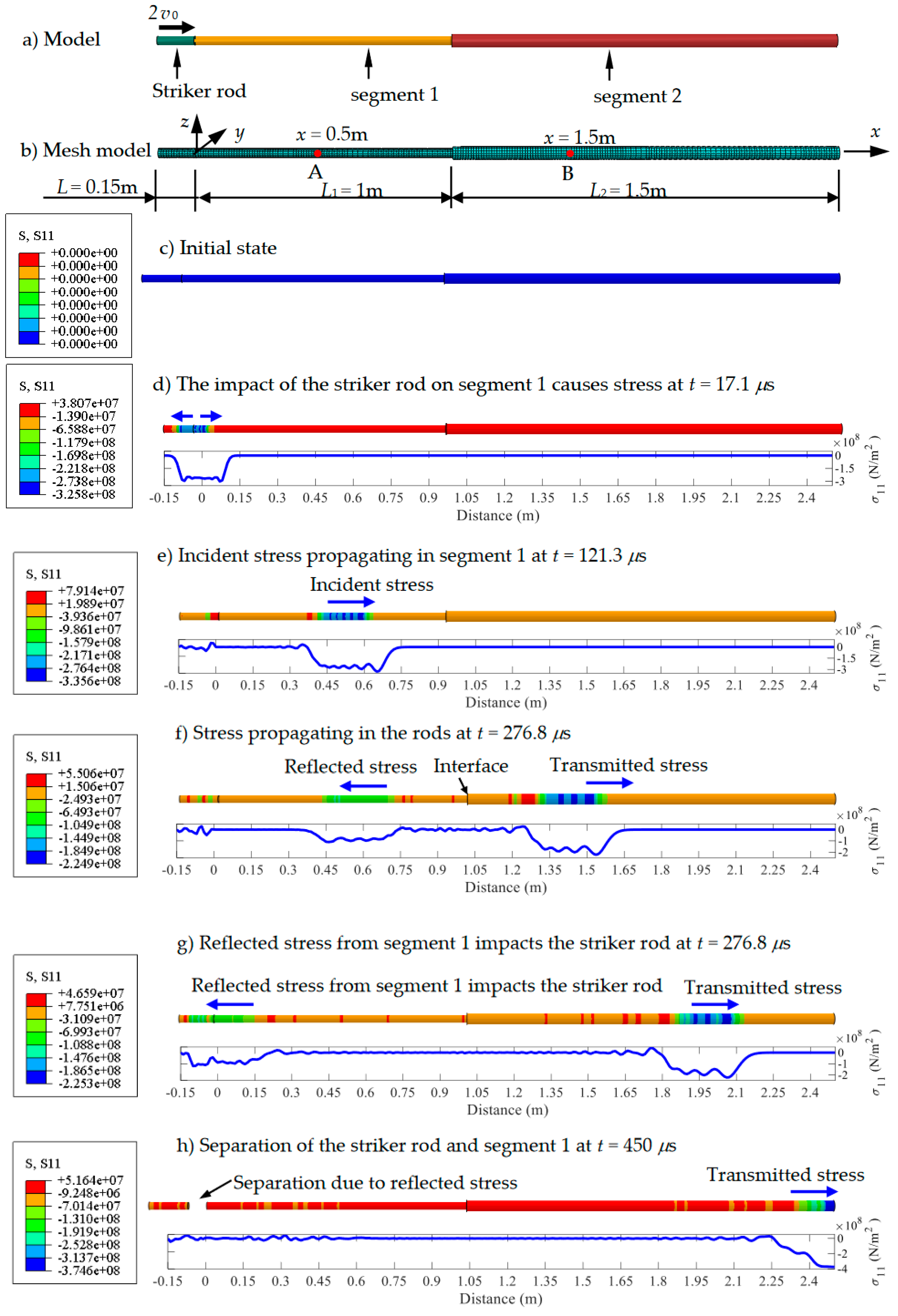
The geometrical shape and finite element mesh of the Rayleigh–Love rod model are plotted in Figs. 5(a) and 5(b), and the relevant parameters used in the Rayleigh–Love rod model are shown in Table 1. Based on Eq. (B3), the elastic material wave velocity c is computed as 5,782.69 m/s. In the Abaqus-based FEM simulations, the solid element-type C3D8R is employed, with 10,947 nodes and 8,448 elements in the model, as shown in Figure 5(b). The detailed stress variations are demonstrated in Figure 5c,h at the time from the initial state to 450 μs.
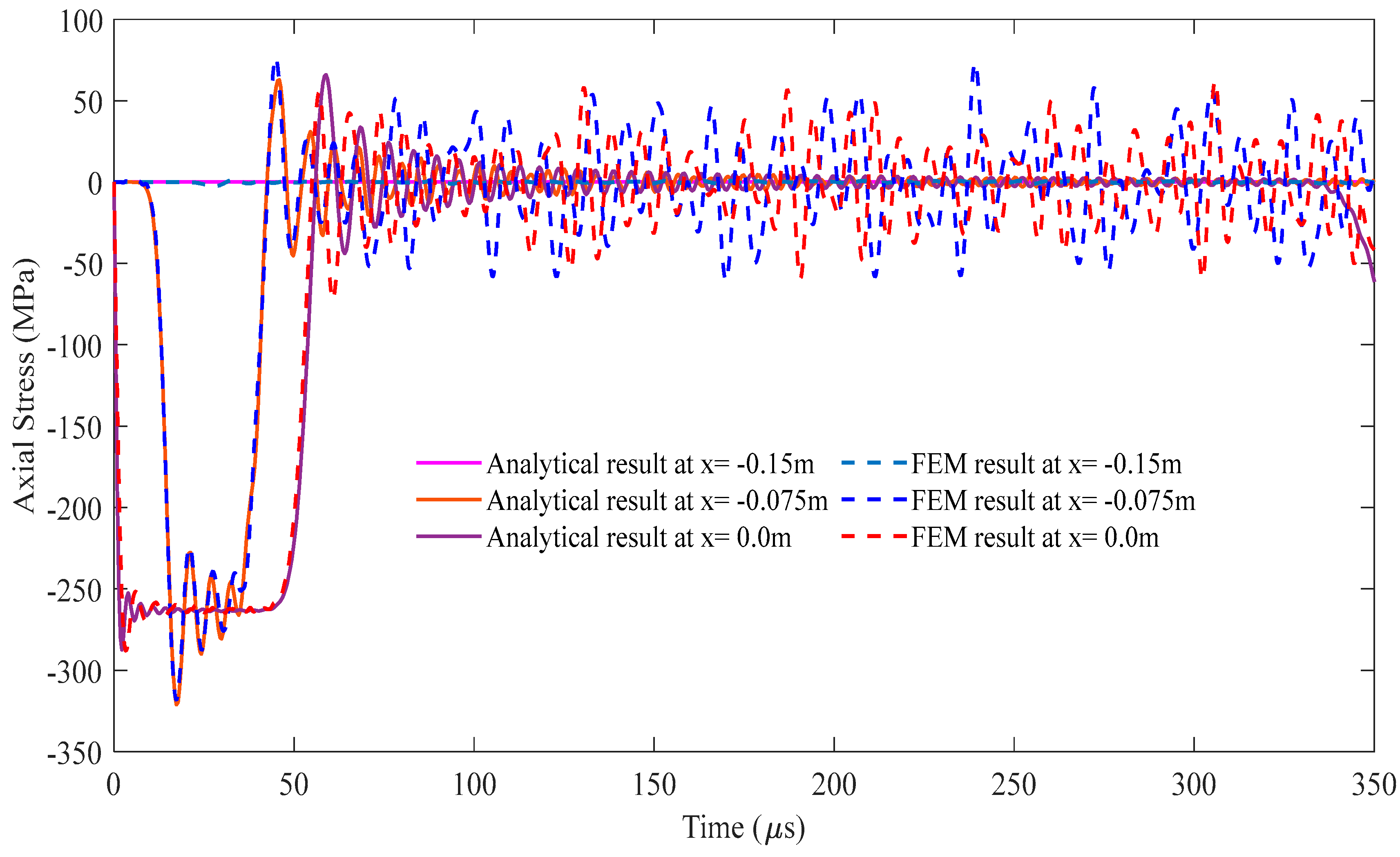
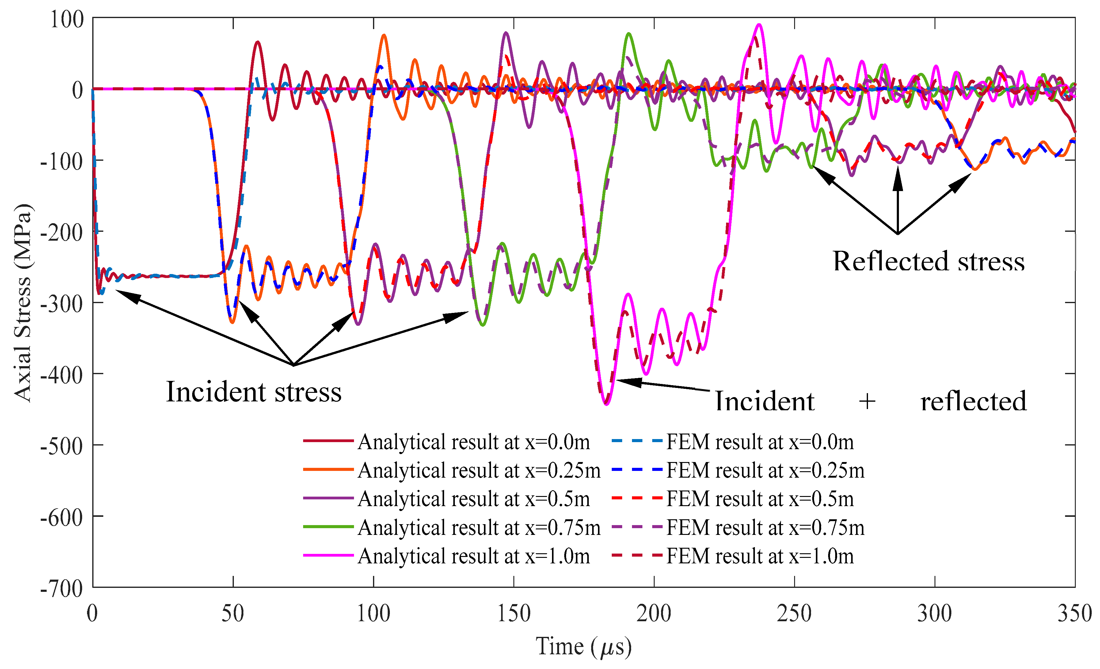
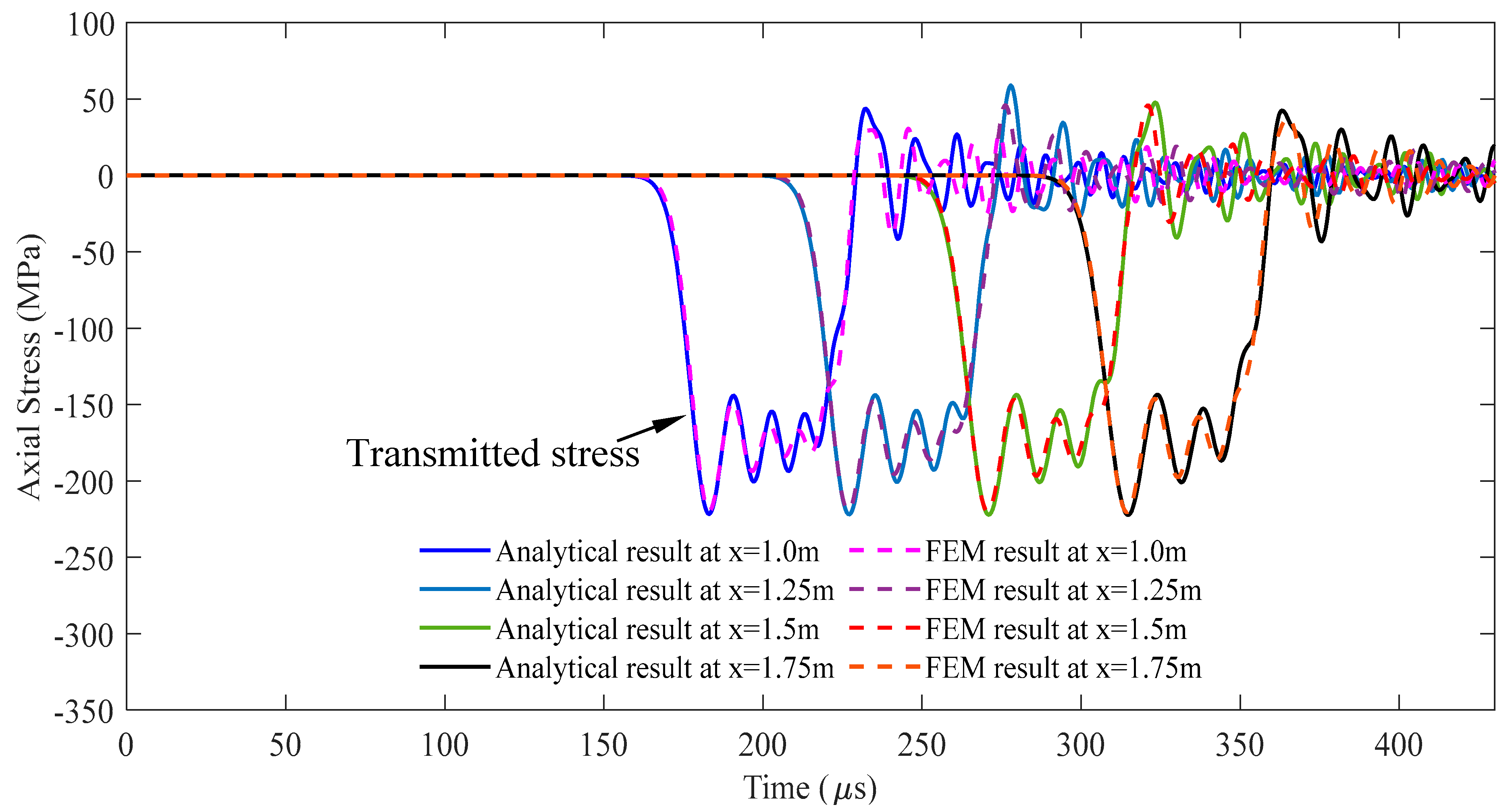
For the cross-sectional area ratio A2/A1 = 2, i.e., A2 = 1.41 × 10⁻³ mm2, the comparisons of the stress responses over time at varying positions at the striker rod, segment 1, and segment 2 between both methods are illustrated in detail in Figure 6, Figure 7 and Figure 8, respectively, through the whole wave propagation duration. A high consistency presents positive evidence for a high degree match between the analytical solutions expressed by Eqs. (24)–(28) and FEM simulation results. It verifies that the correctness of the numerical algorithm used to solve Eqs. (24)–(28) in this study.
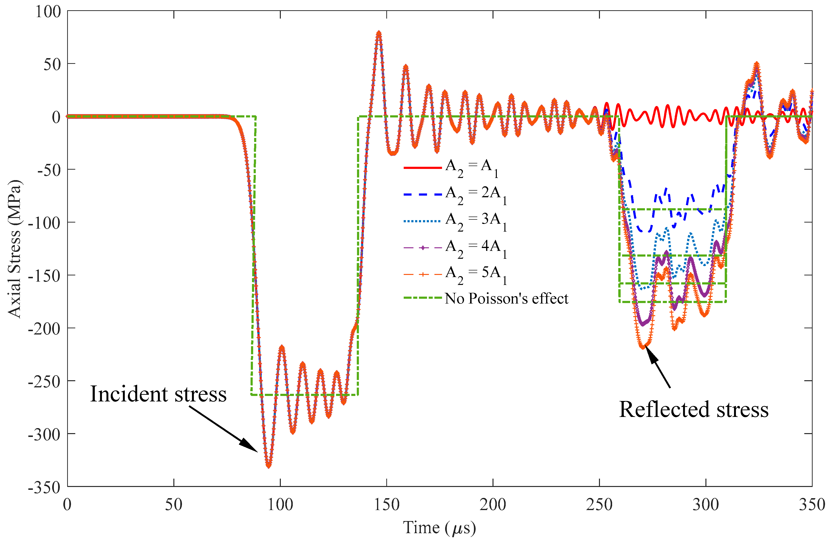
Figure 9 presents the two types of stress responses, incident and reflected stresses, at x = 0.5 m, i.e., point A in Figure 5(b), in segment 1, within the rod based on Eq. (24). The shape of the incident stresses remains unchanged at the period of 90–140 μs as expected. By contrast, the reflected stress at the period of 260–310 μs significantly varies with cross-sectional area A2. In particular, an increase in cross-sectional area A2 results in a corresponding increase in the magnitude of the reflected stresses. When the cross-sectional areas are equal, i.e., A1 = A2, no reflected stresses are observed, signifying the absence of reflected stresses. Moreover, the incident and reflected stresses exhibit the same negative-valued responses.
Figure 9 also shows the stress responses without considering Poisson’s effect. The peak stress values of the incident stress wave are −333.24 and −263.286 MPa, respectively. This finding indicates that the stress under Poisson’s effect increases by 25.57% compared with that without Poisson’s effect. Table 2 shows that the reflected stress values range from 23.84% to 24.55% for the cross-sectional area ratio, A2/A1, varying from 2 to 5. This finding demonstrates that Poisson’s effect has similar stress responses for different cross-sectional area ratios.
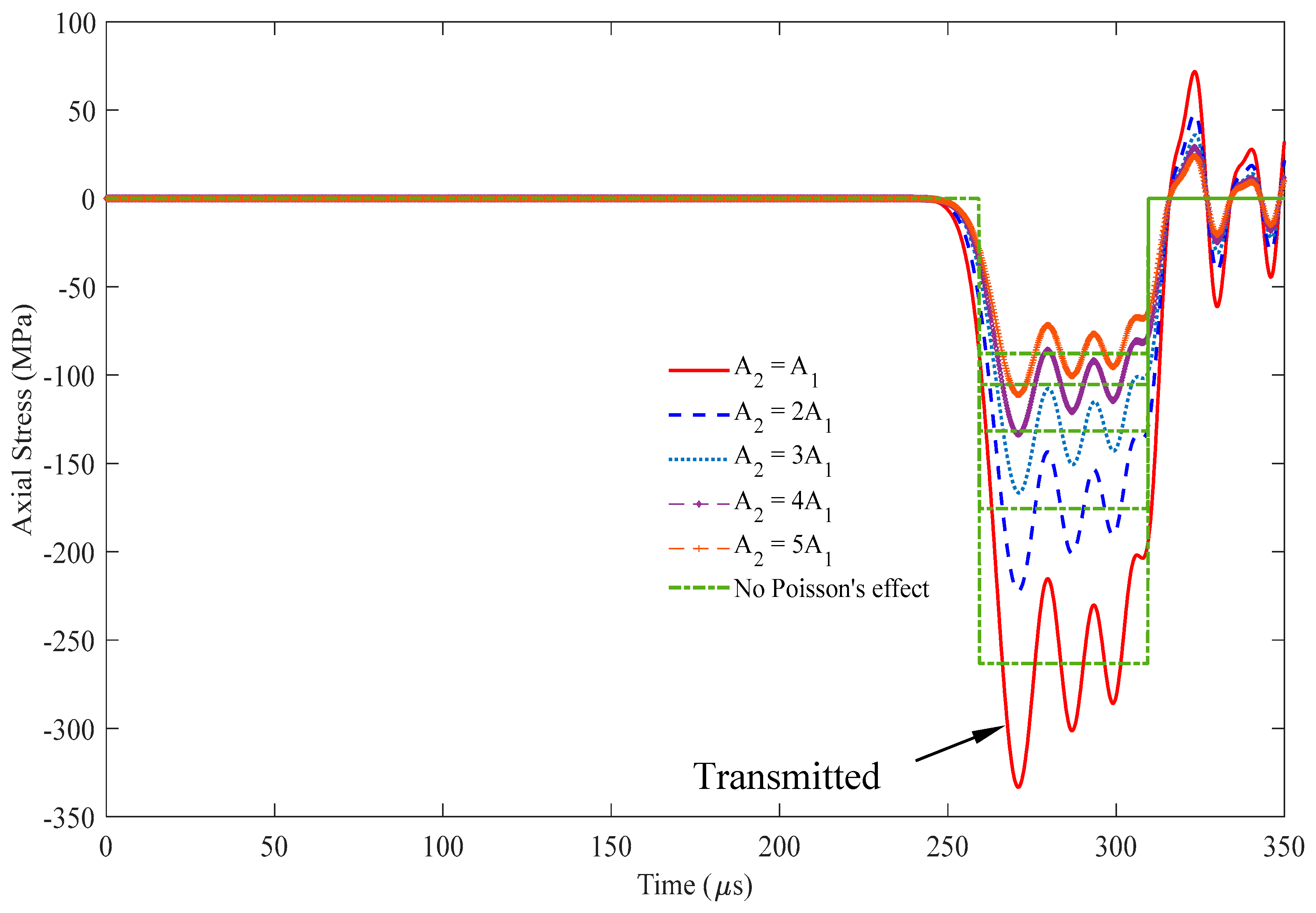
Figure 10 illustrates the stress responses at x = 1.5 m, i.e., point B in Figure 5(b), in segment 2 within the rod based on Eq. (27). The first peak values of this transmitted stress vary with cross-sectional area A2. The transmitted stresses are equal to the incident stress values when the cross-sectional area A1 is equal to A2. In particular, the resulting transmitted stress responses become increasingly intensive as the cross-sectional area A2 increases. Table 3 shows that the stress values have similar stress responses, with and without considering Poisson’s effect and the Poisson’s effect for different cross-sectional area ratios, A2/A1. The waveforms of nonzero Poisson’s ratio oscillate about the waveform of zero Poisson’s value.

3.2. Example 2

The condition in Example 2 is set as a rod with two cross-sectional areas, where cross-sectional area A2 is less than cross-sectional area A1, as shown in Figure 11. Except for the diameters of segment 2, the relevant parameters used in the Rayleigh–Love rod model are listed in Table 1. The diameters of segment 2 are set as 30, 21, 17, 15, and 13 mm instead.
Figure 12 depicts the stress responses, incident and reflected stresses, at x = 0.5 m, i.e., point A in Figure 5(b), in segment 1, within the rod based on Eq. (24) when cross-sectional area A1 is greater than cross-sectional area A2. The shape of the incident stresses remains invariant at the 90–140 μs period regardless of the changes in the cross-sectional areas A2 as expected. Conversely, the reflected stress at the 260–310 μs period significantly varies with alterations in the cross-sectional area A2. A small cross-sectional area A2 leads to intensive reflected stresses. When the cross-sectional areas are equal, i.e., A1 = A2, no reflected stress responses are observed, signifying the absence of reflected stresses. In this scenario, the incident and reflected stresses exhibit opposite signs, indicating that the reflected wave phase is strongly affected by the cross-sectional area ratio at the interface. Table 4 shows that the stress values have similar stress responses with and without Poisson’s effect for different cross-sectional area ratios.
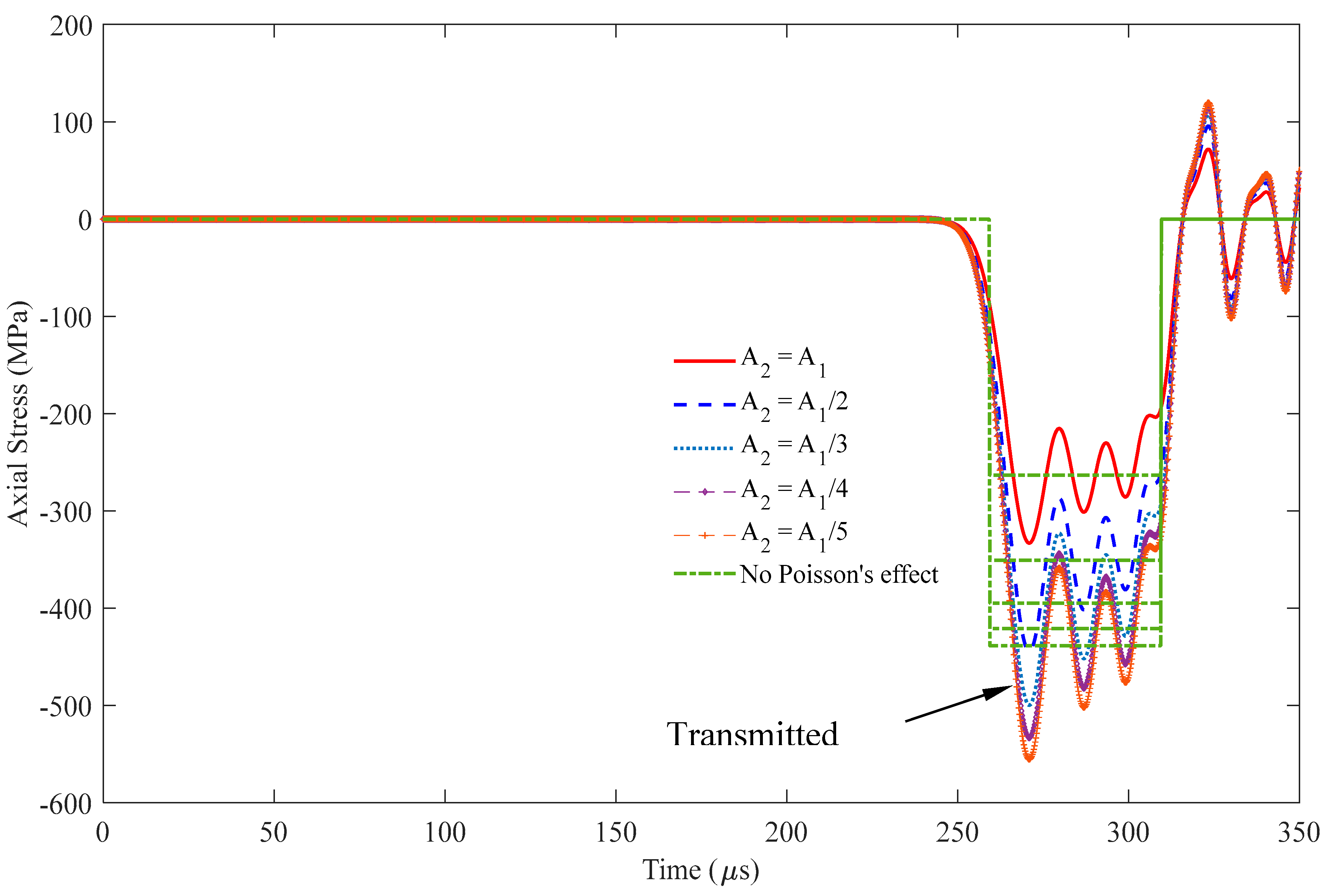
Figure 13 illustrates the stress responses at x = 1.5 m, i.e., point B in Figure 5(b), in segment 2 within the rod based on Eq. (27) when cross-sectional area A1 is greater than cross-sectional area A2. Similarly, a small cross-sectional area A2 leads to highly intensive reflected stresses. When the cross-sectional area A1 is equal to A2, the transmitted stresses are equal to the incident stress values. In particular, the resulting transmitted stress responses become increasingly intensive as cross-sectional area A2 increases. Table 5 shows that the stress values have similar stress responses, A2/A1, with and without considering Poisson’s effect and the Poisson’s effect for different cross-sectional area ratios.

4. Identifying the Positions of Cross-Sectional Area Change and Cross-Sectional Area Ratios in a Rod

4.1. Transmission and Reflection of Stress Wave at Interface

In some engineering diagnosis problems, the damaged position and the condition of the rod inside a cover medium must be identified. The impact-echo method is usually applied for this purpose. The variations in the reflected and transmitted stresses can be presented in terms of cross-sectional area ratio A2/A1 to illustrate the influence of the cross-sectional area change in the rod. The reflected stress σ R and transmitted stress σ T can be expressed as follows by letting α = A2/A1 and substituting it into Eq. (21) and Eq. (22):
σ R = α ρ 2 c 2 ρ 1 c 1 ρ 1 c 1 + α ρ 2 c 2 σ I ,
σ T = 2 ρ 2 c 2 ρ 1 c 1 + α ρ 2 c 2 σ I .
Eqs. (32) and (33) show the relationship between the cross-sectional area ratio and the reflected and transmitted stress. When the cross-sectional area ratio A 2 / A 1 approaches 0, the σR approaches -σI, and σT approaches 2σI; as A 2 / A 1 approaches ∞, the σR approaches σI, and σT approaches 0.
Suppose one knows the first peak stress values, labeled σ I p as the peak incident stress and σ R p as the peak reflected stress. In this case, one can determine the change in the cross-sectional area A2 from the measurement. From Eq. (32), the cross-sectional area ratio α can be rewritten as
α = A 2 A 1 = ρ 1 c 1 ( σ I p + σ R p ) ρ 2 c 2 ( σ I p σ R p ) = ρ 1 c 1 ( 1 + σ R p / σ I p ) ρ 2 c 2 ( 1 σ R p / σ I p ) .
Assume that one measures the wave traveling time t, which is the interval of the first peak of the wave traveling from the sensing point and the first peak of the reflected wave received at the same sensing point. In this case, one can determine the length of Lm between the sensing point and the reflected interface as
L m = 1 2 t c 1 ,
where c1 is the longitudinal wave speed of the rod material. The sensing point is located at a distance Ls from the rod end that is smaller than the embedded length Le, as shown in Figure 14.
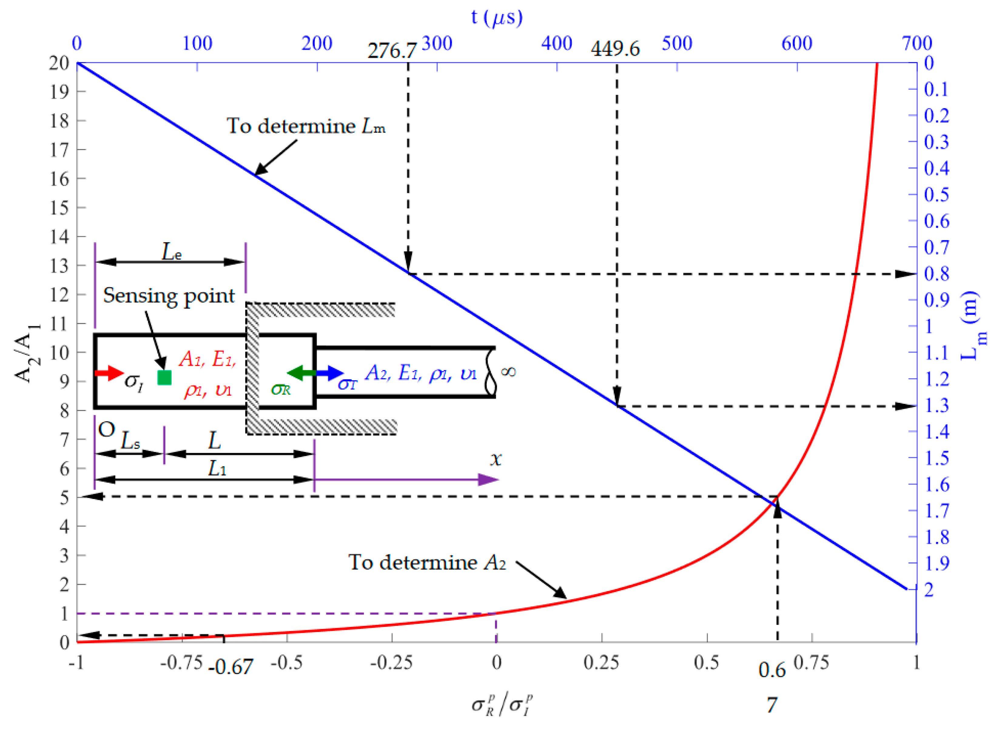
We assume that ρ 1 = ρ 2 , c 1 = c 2 . Figure 15 shows the relation curve (labeled as a red line) between the cross-sectional area ratio A 2 / A 1 and the reflected ratio σ R p / σ I p and the relation curve (labeled as a blue straight line) between the length Lm between the sensing point and the reflected interface and the wave traveling time t. σ R p / σ I p = 1 implies that A 2 = 0 , indicating that the reflected wave is equal in magnitude but opposite in sign to the incident wave. It also represents a free surface at position L1. σ R p / σ I p = 1 implies that A 2 , indicating that the reflected wave is equal to the incident wave in magnitude. When σ R p / σ I p = 0 , this scenario implies that A 2 / A 1 = 1 . If no reflected wave is received, the cross-sectional area in segment 2 remains unchanged, i.e., A2 = A1. For 1 < σ R p / σ I p < 0 , the cross-sectional area A2 is smaller than A1. When 0 < σ R p / σ I p < 1 , the cross-sectional area A2 is greater than A1. The length of L1 = Lm + Ls can be determined from Figure 14. The application in Figure 14 is demonstrated in the following subsection.

4.2. Case Study

  • Case A: Cross-sectional area ratio A2/A1 = 5
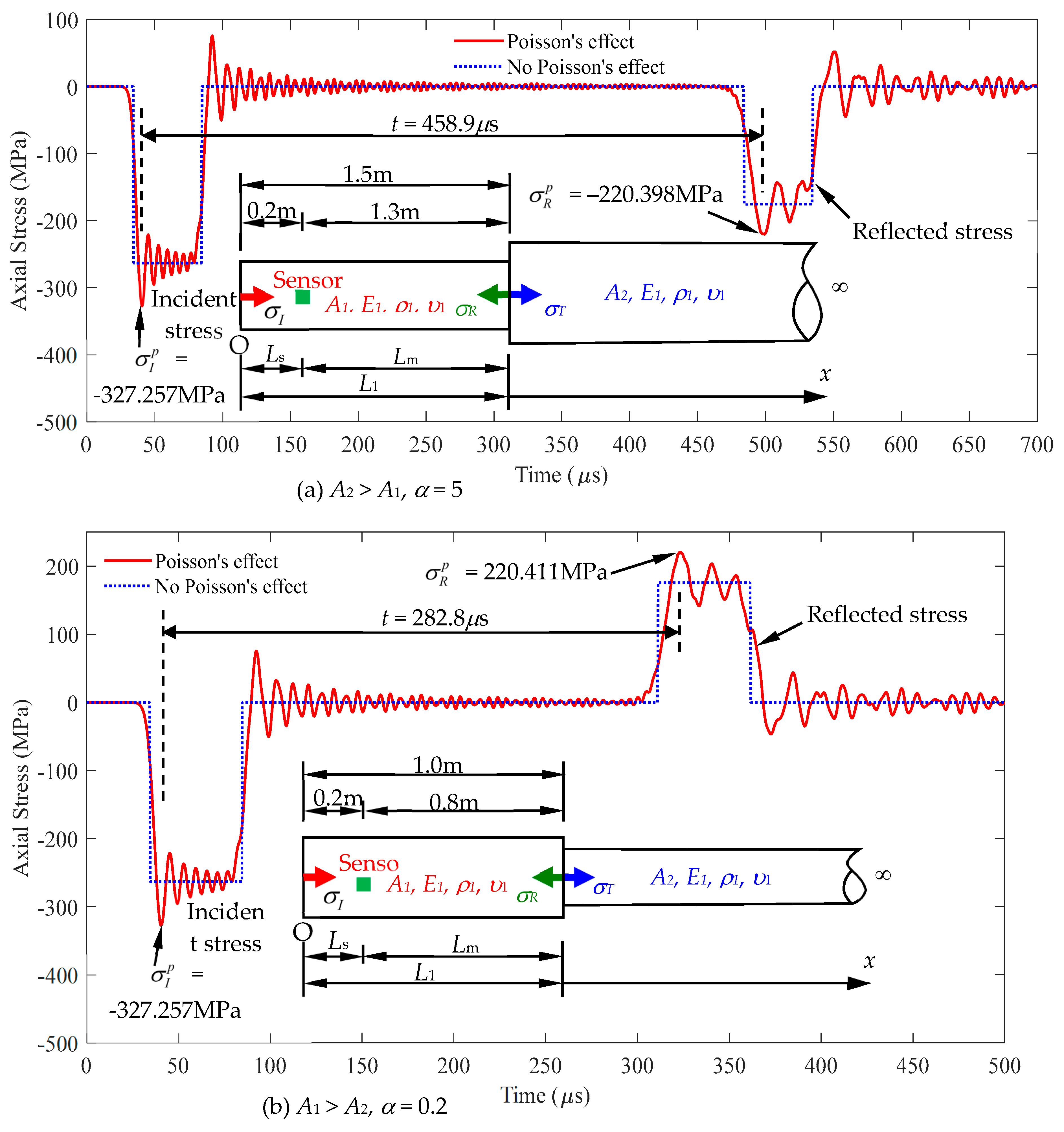
As shown in Figure 15(a), Case A indicates the stress responses at the position of x = Ls = 0.2 m by using Eq. (24). The relevant parameters used in the Rayleigh–Love rod model are identical to those used in Example 1, i.e., Table 1. The diameter of segment 2 is chosen as 67 mm. The first peak incident stress is σ I p = 327.257 MPa , and the first peak reflected stress is σ R p = 220.398 MPa , leading to a reflected ratio of σ R p / σ I p = 0.67 . Figure 15 shows the corresponding cross-sectional area ratio A 2 / A 1 = 5 , which implies A2 = 5A1. The signal received by the reflected stress at time t is 458.9 μs, indicating that Lm = 1.3 m, from the corresponding curve in Figure 14. Given that Ls = 0.2 m is chosen, L1 is calculated as Lm + Ls, equal to 1.5 m.
2.
Case B: Cross-sectional area ratio A2/A1 = 0.2
As shown in Figure 15(b), Case B indicates the stress responses at the position of x = Ls = 0.2 m by using Eq. (24). The relevant parameters of materials are identical to those used in Case A except for the diameter of segment 2. The diameter of segment 2 is set as 13 mm. The first peak incident stress is σ I p = 327.257 MPa , and the first peak reflected stress is σ R p = 220.411 MPa , indicating the reflected ratio of σ R p / σ I p = 0.67 . Figure 15 shows the corresponding cross-sectional area ratio A 2 / A 1 = 0.2 ; thus, A 2   =   A 1 / 5 . The received signal of the reflected stress at t = 282.8 μs corresponds to Lm = 0.8 m in Figure 14. Given that Ls = 0.2 m is chosen, L1 is calculated as Lm + Ls, equal to 1.0 m.
3.
Case C: Influences of different impact velocities and striker lengths on the characteristics of response signals
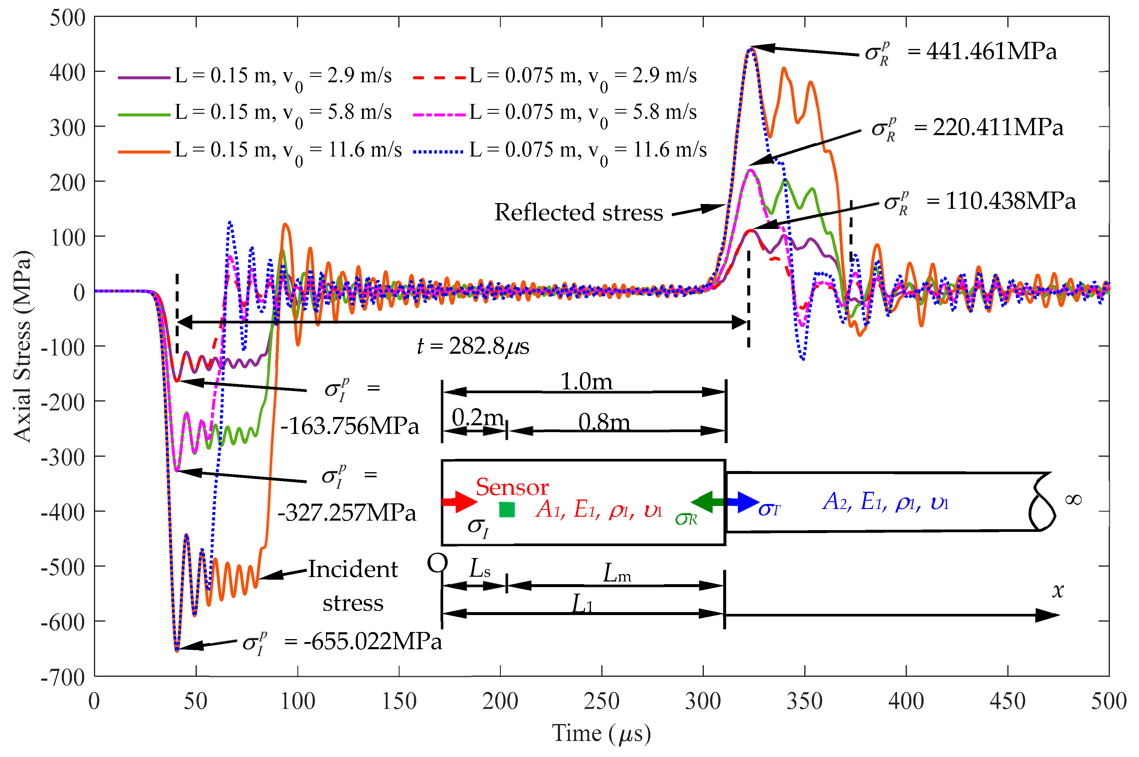
All parameters of case C are identical to those of case B, except for the different impact velocities and striker lengths. As shown in Table 6, the length of the striker rod was varied to 0.15 m and 0.075 m, respectively. Velocities were used for the cases as 2.9 m/s, 5.8 m/s, and 11.6 m/s, respectively. The impact energy of each case that the striker applied on the rod is also listed in Table 6. Stress responses for the different cases of (impact velocity, striker length) combination are shown in Figure 16. This figure demonstrates that the fist peak stress values varied with the impact energy of the striker input to the rod. It is noted that the time interval t between the first peak of incident and reflected wave signal is fixed as t = 282.3 μ s and the stress ratio obtained between the cases of reflected and incident waves is the same for all cases as calculated in Eq. (36).
σ R p / σ I p = 110.438 / 163.756 = 220.411 / 327.257 = 441.461 / 655.022 = 0.67 .
Since all the cases have the same arrival time interval t and the same first peak stress ratio σ R p / σ I p , then have the same length Lm and cross-sectional area A2 from Figure 14. Form this case study, it shows that the impact echo test method proposed in this paper is just provide a suitable impact energy to the inspected rod and measures the response signal at a sensing point. The measurements of the impact velocity and the length of the striker are not required. The location and cross-sectional area ratio of the rod with cross sectional area jump can be identified through the curves in Figure 14.

5. Travel Time History

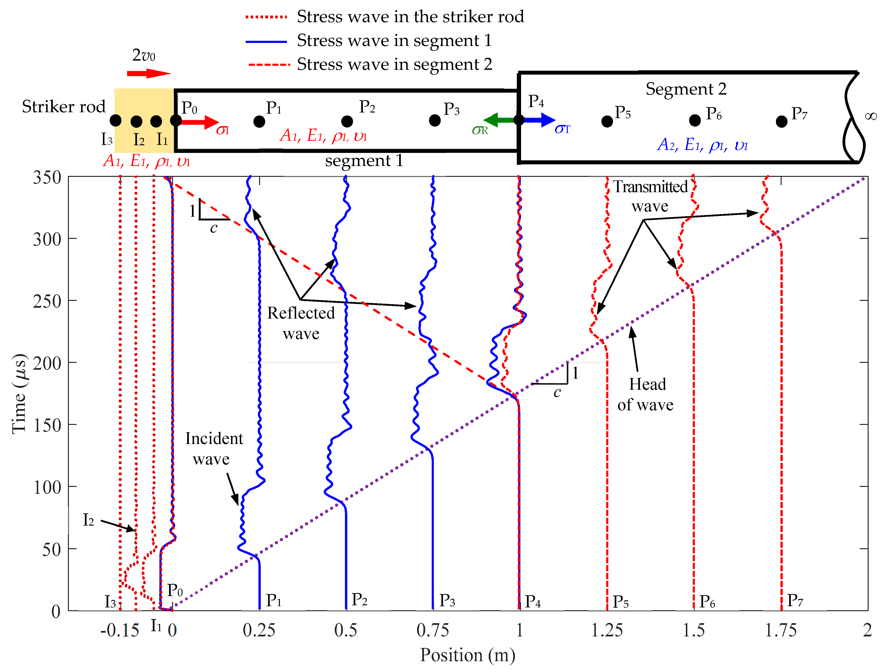
Given the model in Figure 5, Figure 17 illustrates the stress wave travel time history at varying positions in a Rayleigh–Love rod. The stress propagation in the striker rod is presented at Points I1, I2, I3, and P0 (left). Points P0 (right) to P3 represent the presence of the incident and reflected waves. Points P5 to P7 describe the transmitted wave in the semi-infinite rod. The dotted lines represent stress in the striker rod, the solid lines represent the incident and reflected waves, and the dashed lines correspond to the transmitted wave.
The interface of the cross-sectional area jumps off the rod, and all three types of waves (incident, reflected, and transmitted waves) are observed at P4. The incident and reflected waves are detected on the left side of Point P4, whereas the transmitted wave is discernible on the right side. The oscillations of the wave, influenced by Poisson’s effect, are consistently found at each position, leading to stress values surpassing those from traditional wave equations that disregard Poisson’s effect. The phase velocity of the stress waves is equal to c and is determined by Eq. (B3). This finding emphasizes the pertinence of the theoretical approach in aligning closely with the actual wave propagation observed in real tests, suggesting its applicability to structural analysis works.

6. Conclusions

This paper presents a detailed study of the stress wave propagation in a Rayleigh–Love rod characterized by a sudden change in the cross-sectional area after a distance from the impacted end of the rod. Based on the analytical solution by Yang et al. [16], the analytical solutions of the transmitted and reflected stresses in a Rayleigh–Love rod with sudden cross-section variation are obtained. This study highlights the influence of a sudden cross-sectional variation on wave behavior, triggering the reflections and transmissions at the interface of discontinuity. The role of Poisson’s effect is emphasized, shedding light on how it modulates wave behavior by generating additional waves and modulating the amplitudes of both reflected and transmitted waves.
Analyses for impact echo testing cases are also presented to identify the interface positions and cross-sectional area ratio in a Rayleigh–Love rod from the signal variations at specific positions. Examples solved by the FEM are provided to verify the correctness of the modeling and numerical algorithm to the analytical results of this study.
In addition to the forward analysis of Rayleigh–Love wave propagation in rods impacted by a striker rod, an NDT method is proposed to conduct the condition assessment of the rod type of the structure component with a sudden cross-sectional area change within a cover medium based on the measured signals at the measurable zone of the rod to be inspected.
Investigation results show that when determining the cross-sectional area using the σR/σI ratio, the decision to consider or not consider Poisson’s ratio has little influence on the final ratio (Figure 14). Including Poisson’s ratio leads to a similar rate of increase in amplitudes in the incident and reflected stress waves. As a result, the reflected ratio σ R p / σ I p remains nearly the same values, regardless of whether Poisson’s ratio is accounted for or not. However, in practical application, the first peak σ I p and σ R p values can be easily determined through measured signal, and the technique proposed in this study can be applied to conduct the nondestructive evaluation of the location and the ratio of the cross-sectional area change of a rod within a cover medium.
The condition in Example 1 is set as a rod with two segments of different cross-sectional areas, where cross-sectional area A2 is greater than cross-sectional area A1, as shown in Figure 3. First, the accuracy of Eqs. (24) to (28) must be confirmed. Finding the difference between the results derived from these equations and those obtained from the FEM is necessary.

Author Contributions

Chung-Yue Wang: Advisor, Conceptualisation, Methodology, Writing - Review, and Editing. Nguyen Ngoc Thang: Conceptualisation, Methodology, Formal Analysis, Numerical Simulation, Validation, Data Curation, Visualisation, and Writing – Original draft. Helsin Wang: Conceptualisation, Writing - Review, and Editing.

Funding

This research received no external funding.

Institutional Review Board Statement

Not applicable.

Informed Consent Statement

Not applicable.

Data Availability Statement

Data are contained within the article.

Acknowledgments

This paper received no specific grant from public, commercial, or not-for-profit funding agencies.

Conflicts of Interest

The authors declare no conflict of interest.

Appendix A

Derivation of the Rayleigh–Love equation of stress wave propagation in the rod.
Figure A1. The rod and the cross section illustrate the longitudinal and lateral displacement components due to Poisson’s effect.
Preprints 101612 g0a1
The strain–stress relationship from the general Hooke’s law is presented as
ε i j = 1 + υ E σ i j υ E σ k k δ i j σ i j = E 1 + υ ε i j + υ E ( 1 + υ ) ( 1 2 υ ) ε k k δ i j ,
where E is Young’s modulus, and υ is Poisson’s ratio of the rod material.
We assume that uniaxial stress still holds, so that σ y = σ z = 0 . Thus, Eq. (A1) becomes
ε y = ε z = υ E σ x = υ ε x = υ u x .
The lateral displacements are determined as follows:
v = ε y y , w = ε z z ,
where y and z are the coordinates of a point in the cross-section. Substituting Eq. (A2) into Eq. (A3) enables the lateral displacements to be expressed in terms of the longitudinal motion as
v = υ y u x , w = υ z u x .
The expressions for the kinetic and potential energy are required in applying the energy method for the derivation of the equation of motion. The kinetic energy density is
T = ρ 2 ( u ˙ 2 + v ˙ 2 + w ˙ 2 ) .
The strain energy density of this axially loaded rod is determined as follows:
V = 1 2 σ x ε x ,
Then, Hamilton’s equation becomes
t 0 t 1 δ W ˜ d t + δ t 0 t 1 ( T ˜ V ˜ ) d t = 0 ,
where T ˜ = V ρ 2 ( u ˙ 2 + v ˙ 2 + w ˙ 2 ) d V V ˜ = V 1 2 σ x ε x d V W ˜ = W ˜ b o d y + W ˜ s u r f a c e = V Q u d V + S q u d S ,
where W ˜ is the work done by the external forces, including Q as the body force and q as the surface force.
The preceding expressions can be integrated over the area of the section. From Eq. (A4), we can obtain the following by considering the kinetic energy integral:
v ˙ = υ y 2 u x t , w ˙ = υ z 2 u x t .
Then, the following is obtained by substituting Eq. (A9) into Eq. (A8):
T ˜ = 0 L d x A ρ 2 ( u ˙ 2 + υ 2 ( y 2 + z 2 ) ( 2 u x t ) 2 ) d A .
The longitudinal displacement u(x,t) does not depend on the coordinates y and z. Thus, the area integral may be evaluated exactly. The result is
T ˜ = 0 L ρ A 2 { u ˙ 2 + υ 2 k 2 ( 2 u x t ) 2 } d x = 0 L ρ A 2 { ( u t ) 2 + υ 2 k 2 ( 2 u x t ) 2 } d x .
where k 2 = I / A (I is the second moment of area, and A is the cross-section area of the rod) is the radius of gyration of the cross section. The potential energy density is determined as follows:
V ˜ = 0 L d x A 1 2 ( E ε x ) ε x d A = 0 L d x A 1 2 E ε x 2 d A = 0 L E A 2 ε x 2 d x = 0 L E A 2 ( u x ) 2 d x .
The only stress that exists here is σx. Thus, only the body and surface forces compatible with σ exist. Moreover, only the axial body force Q and the end applied tractions σ(0,t) and σ(L,t) exist. Thus, we obtain
δ W ˜ = δ ( V Q u d V + A σ u d A ) = V Q δ u d V + A σ δ u d A = A ( 0 L Q δ u d x + σ δ u | 0 L ) .
The variation of the kinetic and potential energy is
δ I = δ t 0 t 1 ( T ˜ V ˜ ) d t = δ ( t 0 t 1 d t 0 L A [ ρ 2 { ( u t ) 2 + υ 2 k 2 ( 2 u x t ) 2 } E A 2 ( u x ) 2 ] d x ) .
We obtain the following through the procedure of the calculus of variation method:
t 0 t 1 A ( 0 L Q δ u d x + σ δ u | 0 L ) d t E A t 0 t 1 d t { u x δ u | 0 L + 0 L 2 u x 2 δ u d x } + 0 L d x { ρ A u t δ u | t 0 t 1 t 0 t 1 ρ A 2 u t 2 δ u d t } + 0 L d x ( ρ A υ 2 k 2 2 u x t ) x δ u | t 0 t 1 t 0 t 1 d t { t ( ρ A υ 2 k 2 2 u x t ) δ u | 0 L 0 L 2 x t ( ρ A υ 2 k 2 2 u x t ) δ u d x } = 0 .
We obtain the following by rearranging Eq. (A15):
t 0 t 1 0 L ρ [ c 0 2 2 u x 2 2 u t 2 + υ 2 k 2 4 u x 2 t 2 + Q ρ ] δ u d x d t t 0 t 1 [ ( E u x σ + ρ υ 2 k 2 3 u x t 2 ) δ u ] | 0 L d t + 0 L ρ [ u t + ρ υ 2 k 2 3 u x 2 t ] δ u | t 0 t 1 d x = 0 ,
where c 0 = E / ρ .
We can obtain the following by applying the calculus of variation analysis:
t 0 t 1 0 L ρ [ c 0 2 2 u x 2 2 u t 2 + υ 2 k 2 4 u x 2 t 2 + Q ρ ] δ u d x d t t 0 t 1 [ ( E u x σ + ρ υ 2 k 2 3 u x t 2 ) δ u ] | 0 L d t = 0 .
According to variation theory, each expression within the square brackets of the first and second terms in Eq. (A17) must be zero, and body force Q must be neglected. These latter conditions lead to Rayleigh–Love’s equation of motion.
2 u t 2 = c 0 2 2 u x 2 + υ 2 k 2 4 u x 2 t 2 .
They are simultaneously subjected to the essential boundary condition at the ends as follows:
σ = E u x + ρ υ 2 k 2 3 u x t 2 , at x = 0 , and L .

Appendix B

Derivation of the relationship between stress and velocity in a rod.
According to Newton’s second law, we have the following relation for the affected part in Figure B1:
F L d t = m v ,
where m = ρ A d L = ρ A c d t is the mass of the stress wave affected part in a time interval dt, and v is the velocity of the mass m due to the stress wave. The force is F L = σ A .
Figure B1. Schematic of the affected and undisturbed parts of the stress wave propagation in a rod under compression.
Preprints 101612 g0a2
After using the above relations, Eq. (B1) becomes
σ = ρ c v ,
where c is the wave velocity of the elastic material and is determined as follows:
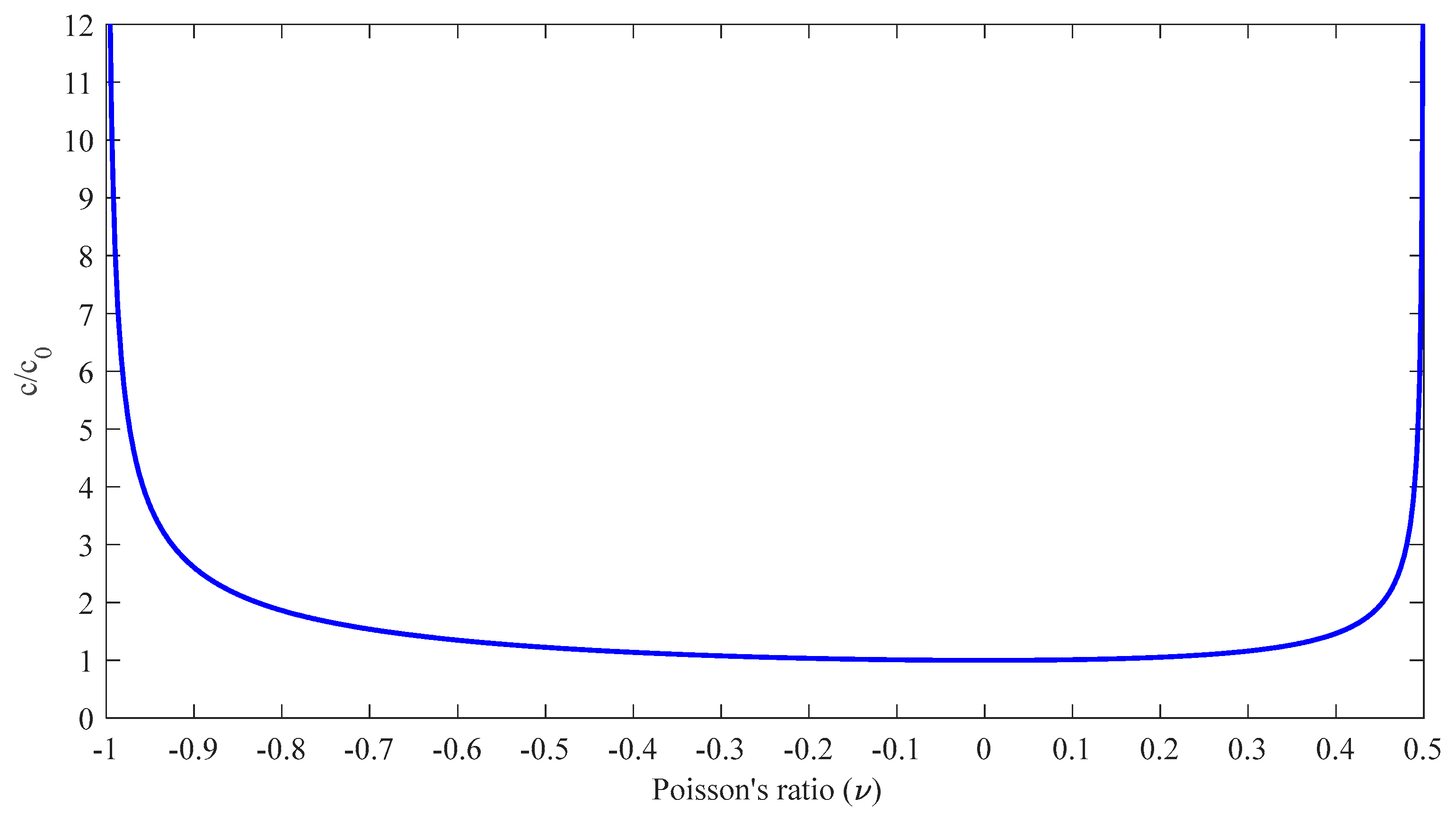
c = λ + 2 μ ρ = ( 1 υ ) E ( 1 + υ ) ( 1 2 υ ) ρ = ( 1 υ ) ( 1 + υ ) ( 1 2 υ ) E ρ = ( 1 υ ) ( 1 + υ ) ( 1 2 υ ) c 0 ,
where λ and μ are Lame’s constants; E and υ are Young’s modulus and Poisson’s ratio, respectively.
The influence of Poisson’s ratio υ on the wave propagation velocity is illustrated in Figure B2. As Poisson’s ratio approaches –1 or 0.5, the ratio c/c0 tending toward infinity indicates a highly sensitive relationship with the extreme values of Poisson’s ratio. This observation reflects the substantial influence of Poisson’s ratio properties on the velocity of wave propagation.
Figure B2. Relationship between Poisson’s ratio and ratio of c/c0.
Preprints 101612 g0a3

Appendix C

Integration of Eqs. (29) to (31).
Equation (29) calculates the stress value at xI at time t of the incident wave as follows:
σ I ( x , t ) = 4 ρ c v 0 π 0 sin L η D 1 sin ( x + L ) η D 1 sin ( t c D 1 η ) ( 1 η ) d η ,
where x is the position determined for the incident stress.
First, the product-to-sum formula is applied to the first two sine functions to conduct the integration in Eq. (C1). The product-to-sum formula for two sine functions is expressed as
sin A sin B = 1 2 [ cos ( A B ) cos ( A + B ) ] .
Then, the product-to-sum formula, combining a sine and a cosine function, is applied as follows:
sin A cos B = 1 2 [ sin ( A + B ) + sin ( A B ) ] ,
which is also applied. Eq. (C1) can become as follows:
σ I ( x , t ) = ρ c v 0 π 0 [ sin ( ( x + t c ) η D 1 ) sin ( ( x t c ) η D 1 ) sin ( ( 2 L + x + t c ) η D 1 ) + sin ( ( 2 L + x t c ) η D 1 ) ] 1 η d η .
The integral properties of the sine function are used as follows:
I = 0 sin ( a η ) η d η = { π 2 , a > 0 π 2 , a > 0 .
Eq. (C4) is transformed as
σ I ( x , t ) = { ρ c v 0 , x c < t < x + 2 L c ρ c v 0 2 , 0 , t = x c , t = x + 2 L c otherwise .
Figure C1. Stress wave propagation without Poisson’s effect is plotted from Eq. (C4) (v0 = 5.8 m/s, c = 5782.69 m/s, ρ = 7850 kg/m3, D1 = 0.03 m; L = 0.2 m; x = 0.5 m; t = 0~450 μs).
Preprints 101612 g0a4
Similarly, the results for Eq. (30) and (31) are, respectively, expressed as
σ R ( 2 L 1 x , t ) = { ρ c v 0 R , 2 L 1 x c < t < 2 ( L + L 1 ) x c ρ c v 0 R 2 , 0 , t = 2 L 1 x c , t = 2 ( L + L 1 ) x c otherwise ,
σ T ( x , t ) = { ρ c v 0 T , x c < t < x + 2 L c ρ c v 0 T 2 , 0 , t = x c , t = x + 2 L c otherwise
where x is the positions determined for the reflected or transmitted stresses.

References

  1. Tesfamariam, S., and B. Martín-Pérez. Stress wave propagation for evaluation of reinforced concrete structures. In Non-Destructive Evaluation of Reinforced Concrete Structures, pp. 417-440. Woodhead Publishing, 2010. [CrossRef]
  2. Sawangsuriya, Auckpath. Wave propagation methods for determining stiffness of geomaterials. Wave processes in classical and new solids 44 (2012). [CrossRef]
  3. Ostachowicz, Wiesław, and Maciej Radzieński. Structural health monitoring by means of elastic wave propagation. In Journal of Physics: Conference Series, vol. 382, no. 1, p. 012003. IOP Publishing, 2012. [CrossRef]
  4. Hu, Yuhang, and Yaowen Yang. Wave propagation modeling of the PZT sensing region for structural health monitoring. Smart Materials and Structures 16, no. 3 (2007): 706. [CrossRef]
  5. Jamaludin, N., David Mba, and R. H. Bannister. Condition monitoring of slow-speed rolling element bearings using stress waves. Proceedings of the Institution of Mechanical Engineers, Part E: Journal of Process Mechanical Engineering 215, no. 4 (2001): 245-271. [CrossRef]
  6. Lee, B. C., and W. J. Staszewski. Modelling of Lamb waves for damage detection in metallic structures: Part I. Wave propagation. Smart materials and structures 12, no. 5 (2003): 804. [CrossRef]
  7. Lee, B. C., and W. J. Staszewski. Modelling of Lamb waves for damage detection in metallic structures: Part II. Wave interactions with damage. Smart materials and structures 12, no. 5 (2003): 815. [CrossRef]
  8. Palacz, Magdalena, and Marek Krawczuk. Analysis of longitudinal wave propagation in a cracked rod by the spectral element method. Computers & structures 80, no. 24 (2002): 1809-1816. [CrossRef]
  9. Krawczuk, Marek, Joanna Grabowska, and Magdalena Palacz. Longitudinal wave propagation. Part II—Analysis of crack influence. Journal of Sound and Vibration 295, no. 3-5 (2006): 479-490. [CrossRef]
  10. Gaul, L., S. Bischoff, H. Sprenger, and T. Haag. Numerical and experimental investigation of wave propagation in rod-systems with cracks. Engineering fracture mechanics 77, no. 18 (2010): 3532-3540. [CrossRef]
  11. Xixiong, W. A. N. G., Y. U. Tao, Y. A. N. Huipeng, D. I. N. G. Jifeng, L. I. Zhen, Q. I. N. Zhaoye, and C. H. U. Fulei. Application of stress wave theory for pyroshock isolation at spacecraft-rocket interface. Chinese Journal of Aeronautics 34, no. 8 (2021): 75-86. [CrossRef]
  12. Fang, Xiangfan. A one-dimensional stress wave model for analytical design and optimization of oscillation-free force measurement in high-speed tensile test specimens. International Journal of Impact Engineering 149 (2021): 103770. [CrossRef]
  13. Love AEH. A treatise on the mathematical theory of elasticity. New York: Dover Publications; 1944.
  14. D’Alembert, J. Researches on the curve that a tense cord forms when set into vibration. Hist. Acad. R. Des Sci. BL Berlin 3 (1747): 214-249.
  15. Yang, Hongsheng, Yulong Li, and Fenghua Zhou. Propagation of stress pulses in a Rayleigh-Love elastic rod. International Journal of Impact Engineering 153 (2021): 103854. [CrossRef]
  16. Yang, Hongsheng, Yulong Li, and Fenghua Zhou. Stress waves generated in a Rayleigh-Love rod due to impacts. International Journal of Impact Engineering 159 (2022): 104027. [CrossRef]
  17. Beddoe, B. Propagation of elastic stress waves in a necked rod. Journal of Sound and Vibration 2, no. 2 (1965): 150-166. [CrossRef]
  18. Fraige, F. Y., and M. H. Es-Saheb. Analysis of Elastic Stress Wave Propagation in Stepped Bars, Transmission, Reflection, and Interaction: Experimental Investigation. Jordan Journal of Mechanical & Industrial Engineering 16, no. 2 (2022).
  19. Payton, Robert G. Elastic wave propagation in a non-homogeneous rod. The Quarterly Journal of Mechanics and Applied Mathematics 19, no. 1 (1966): 83-91. [CrossRef]
  20. Yang, Ke. A unified solution for longitudinal wave propagation in an elastic rod. Journal of Sound and Vibration 314, no. 1-2 (2008): 307-329. [CrossRef]
  21. Rogozhnikov, A. M. Application of the Laplace transform to the analysis of a mixed problem describing the vibrations of a compound rod. Differential Equations 50 (2014): 88-97. [CrossRef]
  22. Wheeler, Gerald F., and William P. Crummett. The vibrating string controversy. American Journal of Physics 55, no. 1 (1987): 33-37. [CrossRef]
  23. Sirota, Lea, and Yoram Halevi. Extended D'Alembert solution of finite length second order flexible structures with damped boundaries. Mechanical Systems and Signal Processing 39, no. 1-2 (2013): 47-58. [CrossRef]
  24. Tanaka, Kichinosuke, Tomoaki Kurokawa, and Kazunaga Ueda. Plastic stress wave propagation in a circular bar induced by a longitudinal impact. In Macro-and Micro-Mechanics of High Velocity Deformation and Fracture: IUTAM Symposium on MMMHVDF Tokyo, Japan, August 12–15, 1985, pp. 317-326. Berlin, Heidelberg: Springer Berlin Heidelberg, 1987.
  25. Mirzajani, Mohsen, Naser Khaji, and Muneo Hori. Stress wave propagation analysis in one-dimensional micropolar rods with variable cross-section using micropolar wave finite element method. International Journal of Applied Mechanics 10, no. 04 (2018): 1850039. [CrossRef]
  26. Gopalakrishnan, S. A deep rod finite element for structural dynamics and wave propagation problems. International Journal for numerical methods in Engineering 48, no. 5 (2000): 731-744. [CrossRef]
  27. Payton, Robert G. Elastic wave propagation in a non-homogeneous rod. The Quarterly Journal of Mechanics and Applied Mathematics 19, no. 1 (1966): 83-91. [CrossRef]
  28. Yang, Ke. A unified solution for longitudinal wave propagation in an elastic rod. Journal of Sound and Vibration 314, no. 1-2 (2008): 307-329. [CrossRef]
  29. Rogozhnikov, A. M. Application of the Laplace transform to the analysis of a mixed problem describing the vibrations of a compound rod. Differential Equations 50 (2014): 88-97. [CrossRef]
  30. Schiff, Joel L. The Laplace transform: theory and applications. Springer Science & Business Media, 2013. [CrossRef]
  31. Yang, Won Y., Wenwu Cao, Jaekwon Kim, Kyung W. Park, Ho-Hyun Park, Jingon Joung, Jong-Suk Ro, Han L. Lee, Cheol-Ho Hong, and Taeho Im. Applied numerical methods using MATLAB. John Wiley & Sons, 2020.
Figure 1. Model for determining the changing cross section A2 and the length L1 embedded in a medium (x > Le) based on stress wave propagation theory. (Note: σI, σR, and σT represent the incident, reflected, and transmitted stresses, respectively; A1 and A2 are the cross-sectional areas of segments 1 and 2 of the semi-infinite rod, respectively; E1, ρ1, and υ1 are Young’s modulus, mass density, and Poisson’s ratio of the rod, respectively.)
Preprints 101612 g001
Figure 2. Scheme of a semi-infinite rod under the impact of a striker rod. (Note: σI is the incident stress, D1 and A1 are the diameter and the cross-sectional area of the striker rod and the semi-infinite rod, respectively; E1, ρ1, and υ1 are Young’s modulus, mass density, and Poisson’s ratio of the two rods, respectively; 2v0 is the impact velocity, used to facilitate the application of the Laplace transform in later derivation.)
Preprints 101612 g002
Figure 3. Scheme of a Rayleigh–Love rod with a sudden cross-sectional area change within a cover medium of x > Le. (Note: σI, σR, and σT represent the incident, reflected, and transmitted stresses, respectively; D1 is the diameter of the striker rod and rod segment 1; D2 is the diameter of rod segment 2; A1 is the cross-sectional areas of the striker rod and rod segment 1; A2 is the cross-sectional area of rod segment 2; E1, ρ1, and υ1 are Young’s modulus, mass density, and Poisson’s ratio of the rod, respectively.)
Preprints 101612 g003
Figure 4. The interface between the two segments of a Rayleigh–Love rod with the same material but different cross-sectional areas. (Note: vI, σI, and uI are the incident velocity, incident stress, and incident displacement of segment 1, respectively; vR, σR, and uR are the reflected velocity, reflected stress, and reflected displacement of segment 1, respectively; vR, σR, and uR are the transmitted velocity, transmitted stress, and transmitted displacement of segment 2, respectively; A1 and A2 are the cross-sectional areas of segment 1 and segment 2 of the semi-infinite rod, respectively; E1, ρ1, and υ1 are Young’s modulus, mass density, and Poisson’s ratio of the two rods, respectively; xI, xR and xT are the positions determined for the incident, reflected, and transmitted stresses in the semi-infinite rod, respectively; xS is the position determined stress in the striker rod).
Preprints 101612 g004
Figure 5. Stress wave propagating in a Rayleigh–Love rod model using solid elements for cross-sectional area ratio A2/A1 = 2.
Preprints 101612 g005
Figure 6. Comparison of the stress wave propagation in the striker rod between the analytical solution and FEM results for the cross-sectional area ratio A2/A1 = 2.
Preprints 101612 g006
Figure 7. Comparison of the stress wave propagation in segment 1 between the analytical solution and FEM results for the cross-sectional area ratio A2/A1 = 2.
Preprints 101612 g007
Figure 8. Comparison of the stress wave propagation in segment 2 between the analytical solution and FEM results for the cross-sectional area ratio A2/A1 = 2.
Preprints 101612 g008
Figure 9. Stress wave propagation for the incident and reflected stresses in some cases of A2A1 observed at x = 0.5 m (impact velocity 2v0 = 11.6 m/s).
Preprints 101612 g009
Figure 10. Stress wave propagation for the transmitted waves in some cases of A2A1 observed at x = 1.5 m (impact velocity 2v0 = 11.6 m/s).
Preprints 101612 g010
Figure 11. Scheme of a Rayleigh–Love rod with a sudden cross-sectional area change from large to small embedded in a cover medium of x > Le. (Note: σI, σR, and σT represent the incident, reflected, and transmitted stresses, respectively; D1 is the diameter of the striker rod and rod segment 1; D2 is the diameter of rod segment 2; A1 is the cross-sectional areas of the striker rod and rod segment 1; A2 is the cross-sectional area of rod segment 2; E1, ρ1, and υ1 are Young’s modulus, mass density, and Poisson’s ratio of the rod, respectively.)
Preprints 101612 g011
Figure 12. Stress wave propagation for the incident and reflected waves in some cases of A2A1 observed at x = 0.5 m (impact velocity of 2v0 = 11.6 m/s).
Preprints 101612 g012
Figure 13. Stress wave propagation for transmitted waves in some cases of A2A1 observed at x = 1.5 m (impact velocity of 2v0 = 11.6 m/s).
Preprints 101612 g013
Figure 14. Diagram for determining the length Lm and cross-sectional area A2.
Preprints 101612 g014
Figure 15. The cross-sectional area A2 and length L1 determined based on the stress signal measured at x = Ls: (a) A2 > A1, (b) A1 > A2.
Preprints 101612 g015
Figure 16. Determine the cross-sectional area A2 and length L1 based on the stress signal measured with different velocities and striker lengths at the position of x = Ls, A1 > A2, α = 0.2.
Preprints 101612 g016
Figure 17. Stress wave travel time history at various positions in the striker rod and Rayleigh–Love rod with a sudden cross-sectional area variation for the incident, reflected, and transmitted waves depending on position and time.
Preprints 101612 g017
Table 1. Parameters used in the Rayleigh–Love rod model
Parameters Values
Diameter of the striker rod 30 mm
Diameter of segment 1 30 mm
Diameters of segment 2 30, 42, 52, 60, 67 mm
Young modulus, E 195 GPa
Poisson’s ratio, υ 0.3
Mass density, ρ 7,850 kg/m3
Striker rod length, L 0.15m
Length of segment 1, L1 1 m
Length of segment 2, L2 1.5 m
Impact velocity, 2v0 11.6 m/s
Table 2. Reflected stresses in case of A2A1
A2/A1 σ R p ( υ ) σ R p ( υ = 0 ) Diff. (%)
1 0 0 -
2 −108.688 −87.762 23.84
3 −163.362 −131.643 24.09
4 −196.481 −157.972 24.38
5 −218.610 −175.524 24.55
Table 3. Transmitted stresses in case of A2A1
A2/A1 σ T p ( υ ) σ T p ( υ = 0 ) Diff. (%)
1 −333.24 −263.286 26.57
2 −222.16 −175.524 26.57
3 −166.62 −131.643 26.57
4 −133.296 −105.314 26.57
5 −111.08 −87.762 26.57
Table 4. Reflected stresses in case of A2A1
A2/A1 σ R p ( υ ) σ R p ( υ = 0 ) Diff. (%)
1 0 0 -
1/2 114.9129 87.762 30.94
1/3 170.8699 131.643 29.80
1/4 204.1672 157.9716 29.24
1/5 226.3654 175.524 28.97
Table 5. Transmitted stresses in case of A2A1
A2/A1 σ T p ( υ ) σ T p ( υ = 0 ) Diff. (%)
1 −333.240 −263.286 26.57
1/2 −444.320 −351.048 26.57
1/3 −499.860 −394.929 26.57
1/4 −533.184 −421.2576 26.57
1/5 −555.400 −438.81 26.57
Table 6. The initial impact kinetic energy ( 1 / 2 m v 0 2 ) of the striker in each case in Figure 16
No. Cross-section
(m2)
Density
(kg/m3)
Impact length
(m)
Initial velocity
(m/s)
Kinetic energy
(J)
1 7.069*10-4 7850 0.15 2.9 3.500
2 5.8 14.000
3 11.6 55.999
4 0.075 2.9 1.750
5 5.8 7.000
6 11.6 27.999
Disclaimer/Publisher’s Note: The statements, opinions and data contained in all publications are solely those of the individual author(s) and contributor(s) and not of MDPI and/or the editor(s). MDPI and/or the editor(s) disclaim responsibility for any injury to people or property resulting from any ideas, methods, instructions or products referred to in the content.
Copyright: This open access article is published under a Creative Commons CC BY 4.0 license, which permit the free download, distribution, and reuse, provided that the author and preprint are cited in any reuse.
Prerpints.org logo

Preprints.org is a free preprint server supported by MDPI in Basel, Switzerland.

Subscribe

© 2024 MDPI (Basel, Switzerland) unless otherwise stated