1. Introduction
The Gifford-McMahon refrigeration cycle [
1,
2,
3,
4,
5] is a thermodynamic process used for low-temperature refrigeration, often in cryogenics. It involves the compression and expansion of gas through a system of coupled piston-cylinders along with heat transfer through heat exchangers. This cycle is particularly effective in achieving extremely low temperatures, such as those required for gas liquefaction and other cryogenic applications. This cycle is commonly used in various cryogenic applications, including the liquefaction of gases like hydrogen. The ability of the Gifford-McMahon cycle to efficiently achieve temperatures below 20K has positioned it as a pivotal technology in cryogenic applications such as liquefaction of gases, superconductivity, and low-temperature research. Beyond its traditional cryogenic uses, recent advancements have sparked interest in harnessing the cycle’s capabilities in emerging energy sectors. This article aims to provide a comprehensive overview of the Gifford-McMahon cycle’s principles and operation, highlighting its potential applications in energy-related fields. We explore how the cycle’s unique thermodynamic characteristics make it an attractive candidate for various energy conversion and storage technologies, including liquefied natural gas (LNG) production, hydrogen liquefaction, and renewable energy storage. Through a detailed analysis of the cycle’s performance and efficiency, we aim to elucidate its advantages and limitations starting from a thermodynamic and exergy analysis. Additionally, we discuss recent research endeavors and technological innovations aimed at optimizing and enhancing the Gifford-McMahon cycle for broader energy applications. Overall, this article seeks to contribute to the understanding of the Gifford-McMahon cycle’s role in shaping the future of energy systems and inspire further exploration into its potential in advancing sustainable energy solutions. In particular, the Gifford-McMahon cycle could be used to liquefy tiny amounts of hydrogen, for example in jewelers and gold factories. In fact, this gas has always been used in goldsmithing. Historically, it has been used in welding, for example for chains. In addition, hydrogen is used to remove stains and clean metals of oxides.
2. Gifford- Mc-Mahon Thermodynamic Cycle
A thermodynamic analysis of the operation of the chiller is therefore necessary [
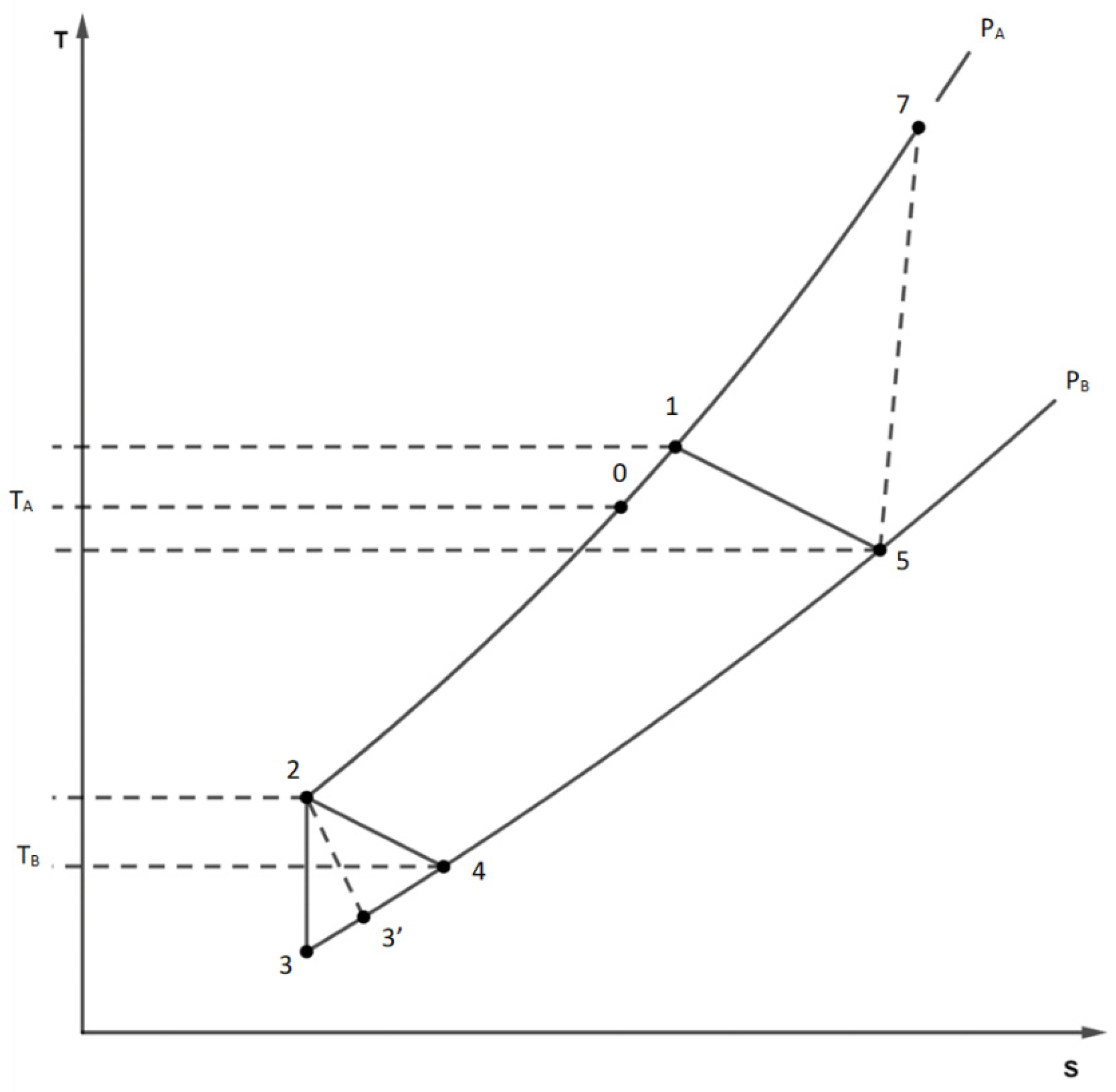
6]. The examination begins by considering the piston at the lower point in state 5 (
Figure 1) with pressure P
5=P
B, temperature T
5 and mass m
5=P
BV /RT
5, with V extensive volume common to the hot and cold chamber.
When the Li inlet valve opens, the cylinder does not move while the pressure rises sharply to P
A (compressor discharge pressure) with a first mass injection, reaching state 7. During the transformation, the energy of the gas in the hot chamber increases by the amount Δ(mCvT)=I
0 Δm so that the group
remains constant, i.e., for the equation of state
Therefore, state 7 assumes the temperature
and the pressure P
7=P
A.
In addition, the mass contained in the hot chamber at the end of the compression is
Then the cylinder rises, expelling the gas from the upper chamber and beginning to fill the cold chamber B where the temperature T
B prevails. A second injection of gas from the valve mixes with the helium escaping from chambre A. The total mass of mixed gas, which is equal to the filling mass of the cold chamber, is therefore.
while the total mass introduced into the chiller through the inlet valve is m=m2-m5.
After the mixing process (at the inlet of the regenerator) the mass m
2 of gas is then in state 1 with a pressure P
1=P
A and a temperature T
1 obtained from the energy balance equation
The production of entropy Δ Sprod,1 in the upper chamber A can be calculated by observing that:
a) a mass m5 enters the thermodynamic conditions PB, T5 of entropy s5,
b) a mass m=m2-m5 in state 0, with entropy s0 enters, through the lamination valve,
c) the mixed mass m2 in the state 1 with s1 comes out of the thermodynamic system
The gas, passing through the regenerator, passes from the temperature T
1 to T
2 with T
1=T
5+ΔT and T
2=T
4+ΔT; the thermal difference ΔT between the round trip is related to the efficiency of the regenerator itself by the
The entropy production related to the transmission of heat inside the regenerator can be calculated considering that:
1) a mass m2 in state 1 enters the outward journey and exits in state 2 with temperature T2 and pressure PA,
2) the mass m
2 on the return enters the condition of state 4 and exits in state 5. We then obtain
At the outlet of the regenerator, the mass m2 of helium in state 2 fills the cold chamber, with the piston in the top dead center.
When the exhaust valve is opened, the gas expands rapidly into the lower chamber and some of it escapes. The expansion of helium in this chamber can be considered isentropic (S
3=S
2), so the depletion law
applies. Hence with simple steps,
where m and P were intermediate between 2 and 3. At the end of the expansion in the cold chamber there is a mass
of gas in state 3, characterized by pressure
and temperature
The leakage of the mass (m
2-m
3) of gas occurs (at variable temperature) with fluid dynamic irreversibility: therefore, it induces a development of entropy. The production of elementary entropy due to the irreversible adiabatic expansion of a mass dm of gas from the generic pressure P (in the cold chamber) to the pressure PB is given by
Subsequently, because of the piston motion, the residual gas also exits the cold chamber. The entire mass m
3 of helium is considered to participate in the refrigeration effect, and it heats up to the temperature T
B (state 4). As a result, the useful amount of heat is
this process is also irreversible due to the temperature difference between the current temperature of the fluid and TB. Finally, in the conditions of state 4, helium passes through the regenerator again, leaving it at temperature T5 and pressure unchanged PB (state 5); A portion of mass m5 (usually very small) fills the hot chamber, while the remaining portion of mass m is ejected. The above reports allow to calculate the characteristics of the fluid states inside the chiller, the gas masses and the entropy productions once the operating temperatures TA and TB, the pressures PA and PB and the volume V of the chambers are assigned.
3. Case Study
The cryogenic generator under consideration, manufactured by Galileo Vacuum Tec (GVT), is designed to achieve operating temperatures significantly below 20K, making it suitable for hydrogen liquefaction. This generator operates using gaseous helium in a closed circuit, without the need for “liquefied gases.”
The cryocooler consists of two main units:
- The compressor group, identified by GVT as D2A, supplies compressed helium to the refrigeration unit. It comprises a hermetic compressor with a power output of 2kW, a refrigerant gas-liquid heat exchanger for cooling the gas after compression, and two series-connected filters for gas purification.
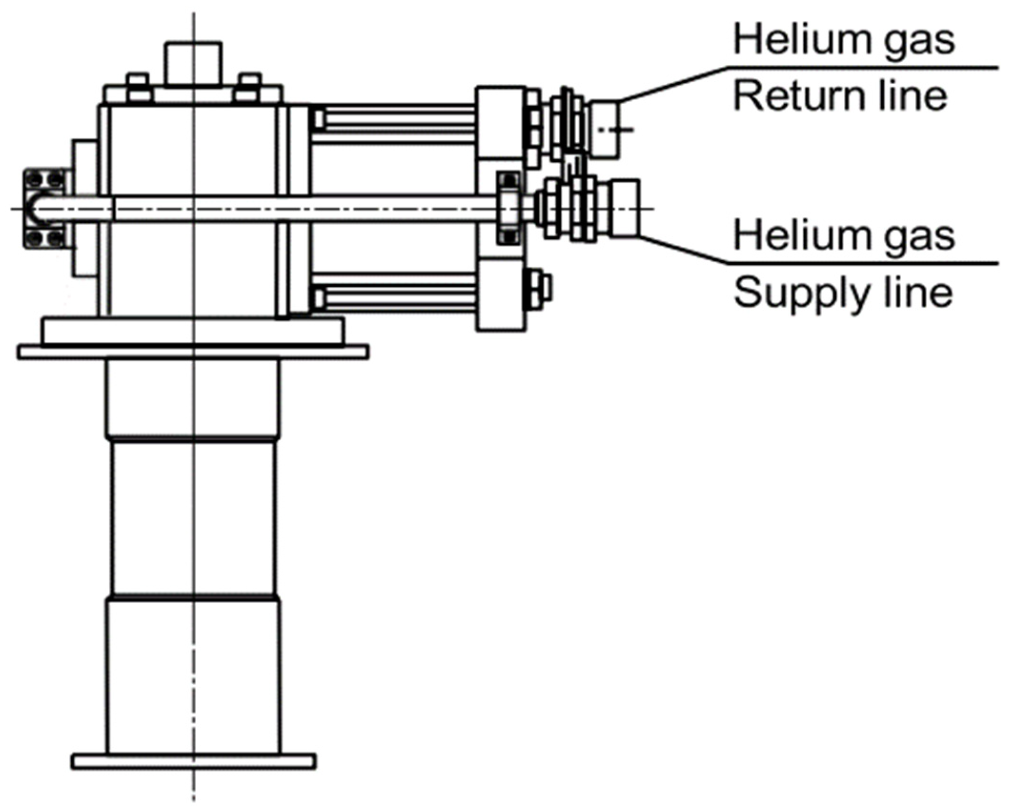
- The refrigerator, referred to as K1, is where the compressed, purified, and initially room temperature gas from the compressor group completes the refrigeration cycle, generating the cooling power (see
Figure 2).
The cycle occurs through the expansion of the gas, facilitated by the coordinated action of the delivery and suction valves, along with a plunger driven by a 30W electric motor integrated into the head of the group. The plunger, situated within the helium expansion zone, encloses an element known as a regenerator, which plays a fundamental role in the realization of the thermodynamic cycle.
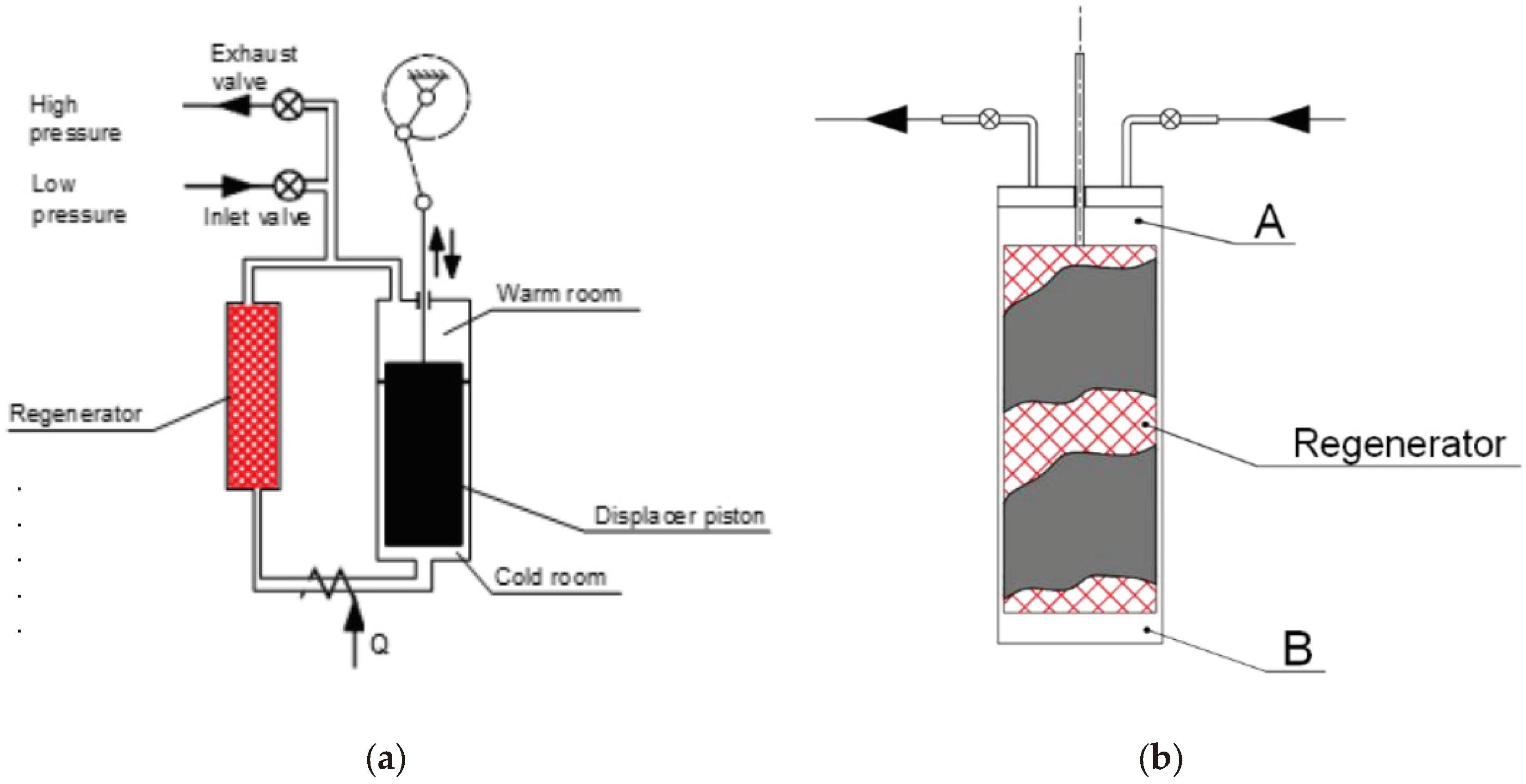
The regenerator consists of a porous matrix with high thermal capacity, comprised of approximately 800 brass or steel screens with very fine mesh (0.1mm). It enables the maintenance of a temperature gradient, ranging from room temperature to cryogenic temperatures, in the direction of gas expansion (see
Figure 3a,b).
Due to this property, the plunger is made of roulon, a special material with a practically negligible coefficient of expansion.
The compressed helium at room temperature, coming from the compressor unit, enters the expansion zone through the porous matrix, resulting in gradual cooling in accordance with [
7,
8]. During the compression phase, the helium flows in the opposite direction to the regenerator, absorbing heat from it, and then returns to room temperature before re-entering the compressor unit.
The interface through which cryogenic power is available to the external environment is the copper flange located at the end of the chiller. The machine operates on a cycle proposed by Gifford and McMahon. This cycle, introduced at the end of the 1950s as a variant of the inverse Stirling cycle, involves the fluid passing through the regenerator and evolving along two isochores, rather than the two isovolumic transformations. A more detailed analysis of the thermodynamic behaviour of the chiller is the focus of this study. The classic scheme is depicted in
Figure 3a, while
Figure 3b illustrates the version developed by Galileo Vacuum-Tec, which involves aligning the displacer and regenerator.
4. Exergy Cycle Analysis
The analysis of the chiller is conducted, in accordance with [
9,
10,
11,
12,
13] by considering the intrinsic irreversibility of the expansion/compression process within the cryogenic group K1, along with those arising from a thermal jump during the displacer’s round trip. Factors such as friction, displacer movement work, and losses due to imperfect thermal insulation are intentionally omitted from the analysis for simplicity. Additionally, the fluid is idealized as a perfect gas with specific heat assumed to be independent of temperature.
The chiller is treated as an open system undergoing non-steady-state operation, wherein, during each cycle, a mass m of helium compressed at pressure PA and ambient temperature TA (state 0) is subsequently expelled at a lower pressure PB and a temperature T5 near room temperature (state 5).
The energy balance and entropy equations, applied to the chiller for a duty cycle, are derived, with mechanical energy terms being neglected for simplicity.
while the consequent exergy balance equation can be written
in these equations with Q and Δ S prod are given respectively the (quantity) amount of heat associated with refrigeration and the entropy production per cycle with I, S, I* the enthalpy, entropy and exergy (flow) per unit mass of the fluid. The temperature of the neutral state corresponds to the ambient temperature. For the purposes of exergy analysis, the inlet exergy is the difference between the flow exergy entering the cryocooler (state 0) and the fictitious state that would occur if the fluid exited at a pressure lower than PB but with a temperature equal to the ambient temperature.
equal to the work required to isothermally compress the fluid in an ideal compressor with compression ratio Π =P
A/P
B. The useful exergy flow is identified with Q[(T
A/T
B)-1] and therefore the exergy efficiency of the chiller is
The exergy loss is, for us, the difference between the actual exit exergy (state 5) and that of the sham state considered above .
The other exergy losses are all attributable to irreversibility. The contributions to entropy production are as follows:
- Δ Sprod,1 due to the irreversible compression of the gas contained in the hot chamber A and its mixing with the gas sent to the compressor;
- Δ Sprod,2 due to the thermal transmission inside the regenerator;
- Δ Sprod,3 due to fluid dynamic irreversibility caused by the abrupt escape of the cold chamber gas following expansion;
- Δ Sprod,4 due to the thermal transmission between the external body and the fluid.
The present analysis is developed with a different criterion from that of other authors [
14] and therefore the results are different mainly due to the different weight attributed to losses in the regenerator.
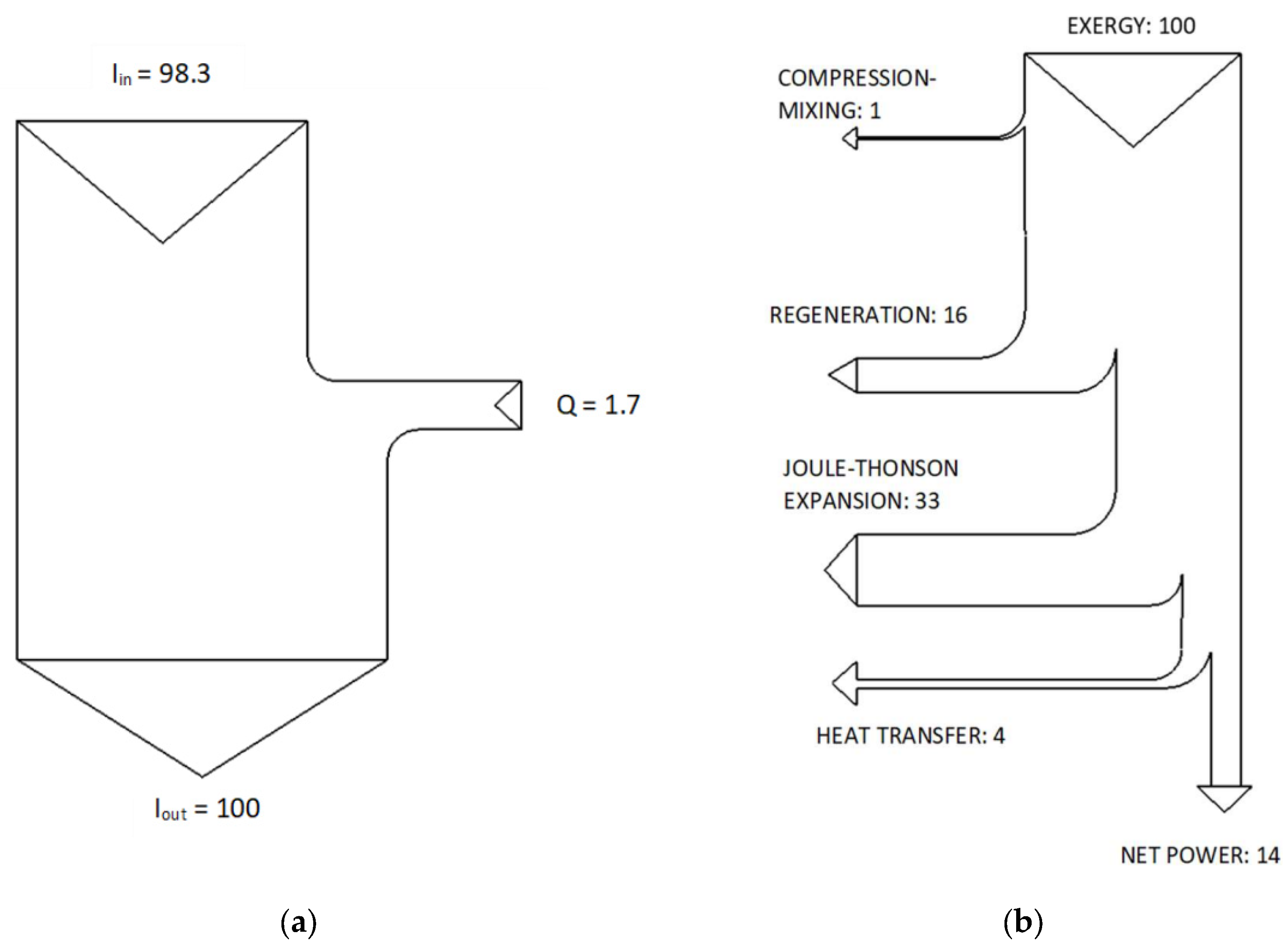
At this point we can draw the Sankey and Grassmann diagrams of the K1 cryocooler. As for the Sankey diagram, which results from the energy analysis, it is shown in
Figure 4a.
As has already been pointed out, frictional irreversibility, which is not entirely negligible, has not been considered. In fact, the seal between the cooler piston and the cylinder is made by means of a non-lubricated roulon ring. However, this irreversibility due to friction are compensated by the small 30W electric motor that determines the motion of the piston, the opening and closing of the inlet and outlet valves, by means of a small crankshaft.
Only the incoming and outgoing enthalpies and the cryogenic power are shown in this energy diagram. The effects due to the compression of the gas and the high-temperature exchanger are outside the considered control volume. The Grassmann diagram, the result of the exergy or “entropic” analysis of the implant [
9] is shown in
Figure 4b. From the exergy diagram it can be seen that once the incoming exergy is unitary and with a regenerator efficiency of 98.5%, the phenomena that induce the most significant losses are: fluid regeneration (46%) and Joule-Thomson adiabatic expansion (33%). On the contrary, the decrease in the availability function due to the heat transfer of cold cell B (4%) and to compression and mixing in the hot chamber (1%) are practically negligible. Completely irrelevant (less than 0.1%) is the exergy returned to the compressor: for this reason it has been neglected.
A comparison of the two diagrams by Sankey and Grassmann shows how much more explanatory the latter is. Therefore, the use of exergy, is useful [
9,
10].
This diagram allows you to have useful information to be able to better perform a realistic simulation.
In fact, after validating the mathematical model with the help of experimental data, an investigation was conducted on the sensitivity of the machine to the variation of the various parameters: the numerical code was used, varying only the efficiency of the regenerator.
It can be seen that a reduction of 0.1% in the efficiency of the regenerator is sufficient to have a COP that is an order of magnitude smaller (see
Table 1).
On the contrary, the losses found in the adiabatic expansion in the hot chamber B are independent of the variation of the operating conditions and marginally influence the “exergy efficiency” of the machine.
Finally, it is observed that the amount of gas that remains in the hot chamber A (after the exhaust valve is closed), which recirculates in the next cycle and which mixes with the gas coming from the compressor, is always negligible. In fact, it represents about 0.8% of the total gas that completes the cycle (see
Table 1) Through this analysis
Theoretically and experimentally, we have found some conclusions that are congruent with other experimental works [
15,
16,
17,
18]: indeed, the regenerator is the most critical part of the machine.
5. Exploring the Gifford-McMahon Cycle: Critical Considerations.
In this section, we delve into a detailed analysis of the Gifford-McMahon refrigeration cycle, considering both numerical values obtained from real-world tests and theoretical comparisons to elucidate its performance characteristics and practical implications. The numerical values presented below are extracted from actual test data archived by the GVT Company, providing insights into the operational parameters of the cycle. These values include operating pressures of 21 and 5 bar, temperatures of 296 and 9.6 K, and a regenerator efficiency of 98.5%. Despite the seemingly low coefficient of useful effect of this machine, averaging 0.017, it is essential to contextualize its efficiency relative to other thermodynamic cycles for a more comprehensive assessment of its performance. For instance, comparing the Gifford-McMahon cycle’s coefficient of performance (COP) to that of an inverse Carnot cycle operating between 9.6 and 296 K reveals a COP of approximately 0.033.
This intrinsic COP is primarily attributed to the substantial temperature differential of around 300 degrees between the heat sources. Furthermore, evaluating the efficiency of the Gifford-McMahon cycle relative to the ideal Carnot cycle allows us to gauge its exergy efficiency, a critical parameter in assessing its thermodynamic performance.
This ratio typically ranges between 0.4 and 0.5, indicating that the Gifford-McMahon refrigeration machine achieves approximately half of the maximum efficiency theoretically possible. However, it is important to note that achieving temperatures close to absolute zero remains the primary objective for such machines. Moreover, the capability of the Gifford-McMahon cycle to operate efficiently under low thermal power conditions, such as 10 W at temperatures around 30 K, underscores its practical significance, aligning with design specifications and real-world requirements. By critically evaluating these considerations, we gain a deeper understanding of the Gifford-McMahon cycle’s performance limitations, its intrinsic efficiency, and its potential for future optimization and application in various thermal engineering contexts.
6. Conclusions
The paper contributes to a deeper understanding of the thermodynamic behavior of Gifford-McMahon cycle refrigerators and provides valuable insights for optimizing their performance in practical applications. Ongoing research aimed at analyzing the cycle’s performance and expanding its applicability in evolving energy world. Through this comprehensive analysis, the author aims to offer a holistic understanding of the Gifford-McMahon refrigeration cycle, its implications across various domains, and the avenues for future exploration and innovation focusing on the possible application of Gifford-McMahon cycle for hydrogen liquefaction.
By means of a theoretical analysis based on the data obtained from a real refrigerator, the performance is thoroughly assessed, with a particular focus on energy and exergy losses. The obtained results are compared with Sankey and Grassman diagrams, providing visual representations of energy and exergy flows within the system. The localization of exergy losses is carefully analyzed to identify key areas for optimization aimed at enhancing efficiency and power output.
The capability of the Gifford-McMahon cycle to operate efficiently under low thermal power conditions, such as 10 W at temperatures around 30 K, appears to be really interesting and the COP of the Gifford-McMahon refrigeration machine achieves approximately half of the maximum efficiency theoretically possible with ideal Carnot inverse cycle.
Acknowledgments
We would like to express our Acknowledgments to Dr. Ing. Nicola Rossi and Mr. Enzo Peroni for the execution of drawings and tables.
Nomenclature
R helium gas constant [J/kgK]
I specific enthalpy [J/kg]
I* specific flux exergy [J/kg]
Q Extensive heat [J]
q specific heat [J/kg]
S Extensive entropy [J/K]
s Specific entropy [J/kgK]
V Extensive volume [m3]
v Specific volume [m3/kg]
γ=Cp/Cv
D2A compressor group,
K1 chiller
References
- Gifford, W. E. U. S. Patent 2966035 (1960).
- McMahon, H.O.; Gifford,W.E. adv Cryog (1960) 354.
- Gifford, W.E. The Gifford-McMhaon cycle Adv Cryog 3 Eng 1966) 11 pp. 152-159.
- Ackermann, R.A.; Acharaya, A.; Gifford, W.E. Adv Cryog Eng 14 (1969) 353.
- Ackermann, R.A.; Gifford,W.E. Adv Cryog Eng 16 (1971) 271.
- Borel, L. Thermodinamique et énergétique. Press politecnique Romandes, 1986.
- Wang C, Gifford P E, Weisend J G, Barclay J, Breon S, Demko J, DiPirro M, Kelley J P, Kittel P, Klebaner A, Zeller A, Zagarola M, Van Sciver S, Rowe A, Pfotenhauer J, Peterson T and Lock J. 2008 Performance Improvement Of A Single Stage Gm Cryocooler At 25 K. AIP Conference Proceedings Advances In Cryogenic Engineering: Transactions of the Cryogenic Engineering Conference - CEC, Vol. 52 vol 985 (Chattanooga (Tennessee): AIP) pp 26– 33.
- Wang, C. and Gifford, P. E. 2002 High Efficiency, Single-Stage GM Cryorefrigerators Optimized for 20 to 40K Cryocoolers 11 ed R G Ross (Boston: Kluwer Academic Publishers) pp. 387–392.
- Kotas,T.J. ‘Exergy concepts for thermal plant’ (First of two papers on exergy techniques in thermal plant analysis) Int. J. Heat and Fluid Flow, 2 (1980), pp. 105-114.
- Kotas,T.J. Exergy method of thermal plant analysis. Ed. Butterworths, 1985; ISBN978-0-408-01350-5. [CrossRef]
- Dincer, I. and Rosen, M.A. Exergy, Energy, Environment and Sustainable Development, Ed. Elsevier Science, 2013; ISBN 978-0-08-097089-9.
- Ahern, J.E. The exergy method of energy system analysis. Ed. Wiley, 1980. [CrossRef]
- Moran, M.J. Avaibility Analysis. Publisher: Prestige Hall, 1982, pp.210-261.
- Thirumaleshwar, M.; Subramannyam, S.V. Two stage Gifford-McMahon cycle cryorefrigerator operating at 20 K Cryogenics (1986) Volume 26, Issue 10, October 1986, pp. 547-555.
- Masuyama, S.; Fukuda, Y.; Imazu,T.; Numazawa,T. Characteristics of a 4 K Gifford–McMahon cryocooler using the Gd2O2S regenerator material, Cryogenics 51, 2011, pp. 337-340. [CrossRef]
- Vikas, R. and Kasthurirengan, S. Recent Advances in Gifford-McMahon Cryocoolers. 2020 J. Phys.: Conf. Ser. 1473 012052 pp. 1-12. [CrossRef]
- Xu, M.; Bao Q.; Tsuchiya, A. and Li, R. Development of Compact 2K GM Cryocoolers Physics Procedia. 2015, 67, pp. 491-496.
- Bao, Q.; Tsuchiya, A.; Xu, M. and Li, R. Experimental Investigation of Compact 2 K GM. 2015; Procedia 67 pp.491–496. [CrossRef]
|
Disclaimer/Publisher’s Note: The statements, opinions and data contained in all publications are solely those of the individual author(s) and contributor(s) and not of MDPI and/or the editor(s). MDPI and/or the editor(s) disclaim responsibility for any injury to people or property resulting from any ideas, methods, instructions or products referred to in the content. |
© 2024 by the authors. Licensee MDPI, Basel, Switzerland. This article is an open access article distributed under the terms and conditions of the Creative Commons Attribution (CC BY) license (http://creativecommons.org/licenses/by/4.0/).


