Preprint
Article

Optimization of Process Parameters for Stir Casting of Tib2 Reinforced In-Situ Composites

Altmetrics

Downloads

79

Views

24

Comments

0

This version is not peer-reviewed

Submitted:

23 March 2024

Posted:

26 March 2024

You are already at the latest version

Alerts
Abstract
The research paper investigates the synthesis of metal matrix composites (MMCs) through the amalgamation of aluminum and silicon carbide particles, employing a two-step mixing methodology called the stir casting method. Metal matrix composites are materials that enhance the capabilities of a metallic matrix by incorporating another material. This leads to better characteristics such as tensile and shear moduli, fatigue and fracture properties, thermal expansion coefficient, and more. Aluminum-matrix composites are a class of materials that possess distinct characteristics that may be modified by altering factors such as the type of reinforcing material, the amount of reinforcement, and the fabrication technique employed to produce the composite. The concept aims to combine the desirable properties of metals and ceramics by incorporating durable refractory particles into a malleable metal structure. The fabrication process employs the stir casting technique, where reinforcing phases are mechanically stirred into a molten matrix to create cast composites with reinforcement volume percentages of up to 30%. The study utilizes Response Surface Methodology to enhance the mechanical properties of the composites through the optimization of manufacturing parameters, including stirring temperature, time, and speed. The study entails analyzing the correlation between different casting conditions and the resulting changes in hardness and tensile strength.
Keywords: 
Subject: Engineering  -   Mechanical Engineering

1. Introduction

A composite material is a substance formed by combining two or more constituent materials that possess distinct physical or chemical properties. The resulting material has unique characteristics that are distinct from those of its original components. The various components maintain their unique and distinct nature inside the final framework. There are several reasons why the new material may be favored: Materials that are stronger, lighter, or less expensive as compared to typical materials. More recently, researchers have also begun to actively embed sensing, actuation, computation, and communication into composites. Composite materials are new-generation materials produced to suit the demands of the rapid expansion of technological advances in industries. [1] Fei Chen, Zonging Chen, Fen Mao; TiB2 reinforced aluminium-based in situ composites manufactured by stir casting. This work gives a review on the mechanical and microstructural features of stir-cast aluminum matrix composites incorporating single TiB2 reinforcement generated from the two halide salts namely, Potassium Hexafluro Titanate and Potassium Tetrafluro Borate. Addition of Titanium Diboride to aluminum has demonstrated an enhancement in its mechanical properties. The microstructural investigation demonstrated that correct stirring intensity and duration are useful in suppressing the formation of severe agglomeration of reinforcements. [2] L.LU, M.O.Lai , Y.Su , h.l.Teo, C.F. Feng; In situ, TiB2 reinforced Al alloy composites. Al MMC reinforced with TiB2 particles was produced via in situ reaction utilizing Al, TiO2, and B2O3. The formation of TiB2 reinforcement particles was confirmed by XRD examination. Mechanical characteristics showed an increase in strength when the amount of TiB2 in the specimens was increased. [3] Dr.S.Periyasamy, M.Aravind, Dr.K.S.Amirthagadeswaran; Optimization of surface grinding parameters for minimal Surface roughness in AISI 1080 using Response Surface Methodology. In this study, an attempt has been made to optimize process parameters for minimal surface roughness using the response surface approach. RSM delivers good results with a minimum number of experiments. [4] Narendra Kumar, Rakesh Kumar Gowtham, Sunil Mohan; In-situ Development of ZrB2 particles and their effect on microstructure and mechanical properties of AA5052 metal matrix composites. [5] R.Keshavamoorthy, Sadhanandha Mageri: Microstructure and mechanical characteristics of Al7075-TiB2 In-Situ composites. Al 7075 – TiB2 composites were manufactured by the stir casting process. The temperature was set around 810 ºC, the Speed of 200rpm, and the Time of about 20 minutes. TiB2 is altered as 0% and 8.5% and the mechanical properties are in direct proportionality with the presence of TiB2 particles. [6] B. Ravi, B. Balu Naik, J.Udhayapraksh: Characterization of aluminum matrix composites manufactured by stir casting process. B4C content is varied to AA6061 matrix material and a direct proportionality of hardness and tensile qualities were obtained. Stir casting was done under continuous parameters of Temperature 850 ºC, Speed 400 rpm, and Time 10-15 minutes. [7] Pardeep Sharma, Satpal Sharma, Dinesh Khanduja; Production and characterization of AA6082-(Si3N4 + Gr) stir cast hybrid composite. Compared al6082 with Gr and Si as distinct reinforcement particles generated by stir casting at constant temperature and speed. [8] A.B.Sarmasti, M.Yazdanirad,M.Nauri Khezrabad,m.Kharbalaie; Effect of alumina particle size and heat condition of casting on microstructure and mechanical properties of stir cast Al-Al2O3 composites. Researched Aluminium composite manufacture with alumina by stir casting technique carried out at 800 °C and identified the optimum amount required for better qualities. [9] Ranjith Bauria and M.K.Surappa; Processing and characteristics of Al-Li-SiCp Composites. Heat-treated the composite samples and observed a proportionality increase with the untreated samples. [10] Ibrahim Ozbek; A study on re-solution heat treatment of AA2618 aluminum alloy. Investigated the aging process on solution-treated samples and discovered that aged samples showed an increase of roughly 15-20% rise in their hardness value than untreated samples.

2. Experimental Procedure

2.1. Fabrication

The stir casting apparatus consists of conical shaped graphite crucible utilized for manufacturing of AMCs, as it withstands high temperature which is more than needed temperature [850°C]. This crucible is set in muffle which is made up of high ceramic alumina. Around which heating element is coiled. The coil which works as heating element is Kanthol-A1. This sort of furnace is called as resistance heating furnace. It can work up to 900°C which can be attained within 45 min. Aluminium, in liquid stage is strongly reactive with ambient oxygen. Oxide production occurs when it comes in touch with the open air. Thus, all the process of stirring is carried out in closed chamber with argon gas as inert gas in order to avoid oxidation. Closed chamber is made with aid of steel sheet. This lowers heat loss and gas transmission as compared to open chamber. A ‘K type’ Temperature thermocouple whose working range is -200°C to 1250°C is used to record the present temperature of the liquid. Due to corrosion resistance to environment, EN 24 steel is selected as stirrer shaft material. One end of shaft is linked to 0.5 hp PMDC motor with flange coupling. While at the other end blades are welded. 4 blades are bonded to the shaft at 45°C. A steady feeding rate of reinforcement particles is necessary to avoid coagulation and segregation of the particles. This can be performed by employing hopper. Aluminium alloy matrix will be created in the crucible by heating aluminium alloy ingots in furnace. A stirring action is initiated at slow rate of 30 rpm and increased to desired rpm (200-400) with speed controller. A mixture of reinforcing salts (K2TiF6 and KBF4) is to be included in the metal matrix at semisolid level approximately 700°C. Dispersion time is should be taken as 6 minutes.

2.1.1. Procedure

Stir casting procedure starts with inserting empty crucible in the muffle. At first heater temperature is set to 500°C and then it is gradually increased up to 850°C. High temperature of the muffle helps to melt aluminium alloy fast, reduces oxidation level, enhance the wettability of the reinforcing particles in the matrix metal. Aluminum alloy Al6063 is utilized as Matrix material. Required quantity of aluminum alloy is cut from the raw material. Aluminum alloy is cleaned to remove dust particles, weighed and then poured in the crucible for melting. During melting argon gas is used as inert gas to form the inert atmosphere around the molten matrix. Powders of organic salts K2TiF6 and KBF4 were utilized for making TiB2 reinforcement. 1% by weight of pure magnesium powder is used as wetting agent. At a time, total 700 gram of molten composite was treated in the crucible. Required quantities of reinforcing powder and magnesium powder are weighed on the weighing machine. Then it is fully combined with each other. Prior to completing the test this combination is kept for heating in another heater.
Organic salts (K2TiF6 and KBF4) responsible for reinforcements creation are heated for half an hour and at temperature of 200°C. When matrix was in the totally molten condition, Stirring is started after 2 minutes. Stirrer rpm is progressively increased from 0 to 300 RPM with the help of speed controller. Temperature of the heater is set at 850°C which is below the melting temperature of the matrix. A homogeneous semisolid state of the molten matrix was produced by churning it at 850°C.Pouring of preheated reinforcements during the semisolid stage of the matrix enhance the wettability of the reinforcement, minimizes the particle settling at the bottom of the crucible. Reinforcements are poured manually with the help of conical hopper. The flow rate of reinforcements measured was 0.5 gram per second. After stirring 15 minutes at semisolid stage slurry was reheated and kept at a temperature of 850°C to make sure slurry was entirely liquid. Stirrer RPM was then gradually dropped to the zero. The stir casting device is manually kept side. Then the stir molten metal along with the salts is held at different temperatures for 30 minutes. This makes the reaction to take place to form TiB2 from the salts and Aluminium matrix. Then molten composite slurry is put in the metallic mould. Mould is preheated at temperature 400°C before pouring of the molten slurry in the mould. This makes sure that slurry is in molten condition throughout the pouring. While pouring the slurry in the mould the flow of the slurry is kept consistent to avoid entrapment of gas. Then it is rapidly quenched with the help of air to minimize the settling time of the particles in the matrix.

2.1.2. Fabrication Parameters

Fabrication parameters are stirring speed, stirring temperature, reinforcement preheat temperature, stirring time, inert gas used and pre heat temperature of mould and are shown in the Table 2.1. Specimens were casted by altering three casting parameters including Stirring Temperature, Stirring Time and Stirring Speed utilizing Bottom pouring type stir casting furnace. Each of the above process parameters consists of three separate levels. The parameters and the levels were shown in Table 2.1.
Response Surface Methodology was applied to optimize the parameters. RSM aids in improving a response (output variable) which is influenced by numerous independent variables (input variables). The major importance of applying RSM approach is its applicability in few investigations rather than going for whole physical experiment which is very time inefficient and expensive. Box Behnken designed an experimental setup for response surface methods to determine the ideal answer. The total number of experiments selected was seventeen. The sequence of tests was offered by Design Expert program as indicated in Table 2.2.
For three factors and three levels there will be a total of 13 experiments. The number of center blocks selected was one. Fabrication parameters were tabulated in Table 2.3.
By the reaction of two salts with the Aluminum matrix material TiB2 is formed. K2TiF6 and KBF4 were added in the ratio of 1:2. Hence 16 g of K2TiF6 and 32g of KBF4 were added.

2.2. Micro Structure Analysis

The casted sample was cleaned using abrasive silicon carbide paper. Polishing was done in a step on each by abrasive paper. Then the specimen was thoroughly washed, dried and again polished on the velvet cloth. The sample was etched with Keller’s reagent. This highly polished surface was observed and photographs were captured using Optical Metallurgical Microscope

2.3. Hardness

Brinell hardness measurements were carried out on the composite samples by using standard Brinell hardness tester. Brinell hardness measurements were carried out in order to investigate the influence of particulate weight fraction on the matrix hardness. Load applied was 250kg and indenter was a steel ball of 5 mm diameter.

2.4. Heat Treatment

The specimens were prepared to be solution heat treated to 560 °C for about 1 hour. During hardening solutes starts moving along the solvent matrix. Here the solvent refers to the major solute present in the material. It moves to and fro along the solvent and seats on its respective position to make it seems to be uniformly distributed. It is then quenched in water. After water quenching, the particles stay in their respective positions permanently thus accounting for improved properties. Quenching is done not only to improve its strength but also to cool it rapidly enough to prevent the alloying elements (solutes) from precipitating on cooling. The delay in time from heating chamber to water to quench is about 5 to 15 seconds. After quenching, the specimens were artificially aged at 200 °C for about 2 hours. This ageing helps alloying elements begin to form ordered arrays of atoms in Aluminium matrix. These arrays are called GP zones and they strengthen the Aluminium.

2.5. Tensile Test

The tensile testing of the composite was done using UTM. The specimens were prepared according to ASTM standard specimens with 60mm gage length were used to evaluate ultimate tensile strength. As the force on the specimen is increased and as soon as the yield strength is reached the material will begin to deform plastically through the movement of dislocations. Dislocations are mono-dimensional defects inside crystals that move mainly through shear stress on the slip plane. What is important to understand is that dislocations will move more easily and with more ease through shear so they will be more encouraged to move in the shear planes of the component. As the deformation proceeds new dislocations are formed and will begin to pile up and interact one another. This is called strain hardening and it is, by all means, an increase of the mechanical resistance of the material due to plastic deformation. At a certain point the dislocations become so many and are so piled up that no more dislocations be created. At this point the increase in stress due to the decrease in the cross-sectional area (cause by the conservation of volume) becomes greater than the increase in the stress that the material can carry due to strain hardening. But the test carries on, trying to keep the deformation rate constant and thereby increasing the force. Then the instability nature comes into act and it will lead to necking or localized plastic deformation of the specimen in a small region inside the test area. Necking in a cylindrical tensile specimen is symmetrical around the tensile axis if the material is isotropic. The reason for the tilted angle of failure is due to the maximum shear plane will be at 45° in respect to the principal stress plane. This is why tensile tests "sometimes" result in a break that is at 45°C angle to the pull axis. In cylindrical specimens this manifests itself in the typical cup and cone shape of the fracture surface.
After preparing the composite specimens, the output responses values were measured. Those includes hardness (before and after heat treatment) and tensile strength. The results were tabulated in Table 2.4. The output responses were measured and entered into the design layout.

3. Result and Discussion

3.1. Hardness (Before Heat Treatment)

Analysis of variance:
The ANOVA table for hardness (before heat treatment) was obtained. The results are presented in Table 3.1.
ANOVA technique was used to find out the influence of each factor considered on the response factor. Its speciality is its ability to find the significance of the factor on the response. The F-value shown in table 3.1 should be maximum. Values of “prob>F” less than 0.0500 indicate model terms are significant. It reveals that Speed and Time has significant effect on Hardness (BHT).Preprints 102096 i001
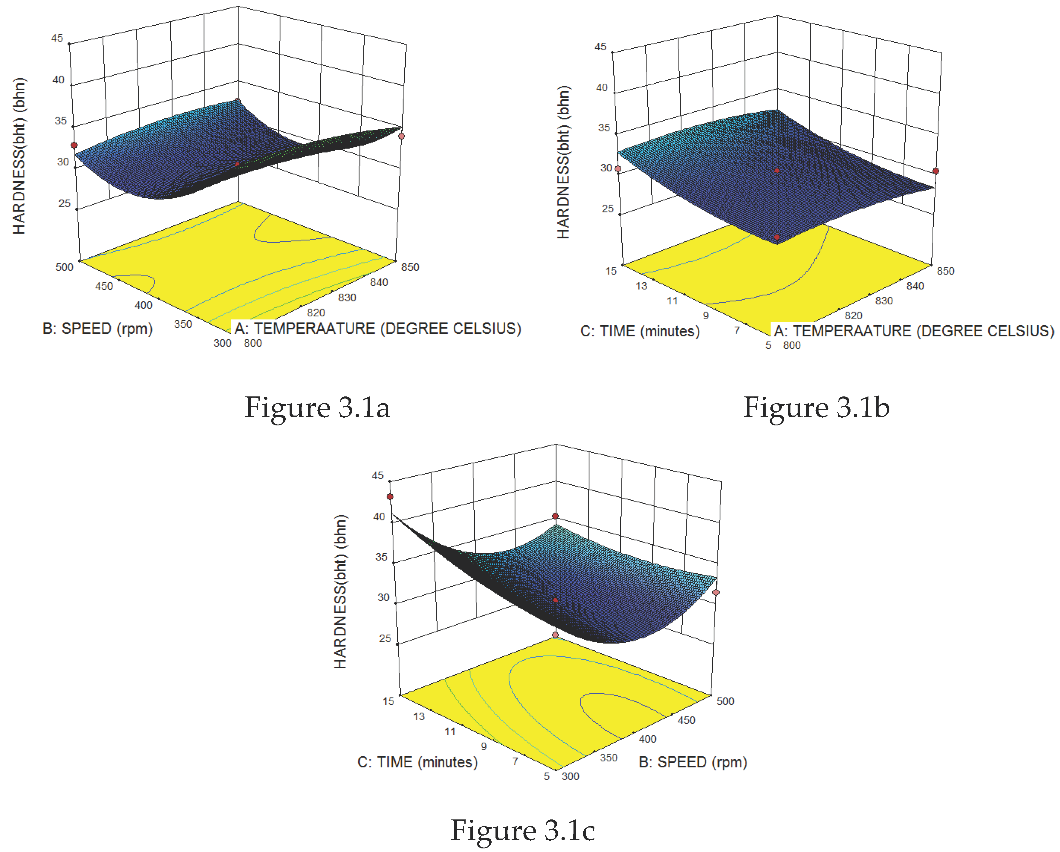
It is clear from Figure 3.1a and 3.1b that hardness decreases if speed and temperature increases. From Figure 3.1c it is seen that hardness increases with increase in time. Therefore, the combination of control factors for highest hardness should consist of minimum speed, minimum temperature and maximum time.

3.2. Tensile Test

Analysis of variance:
The ANOVA table for tensile strength was obtained. The results are presented in Table 3.2. Preprints 102096 i002
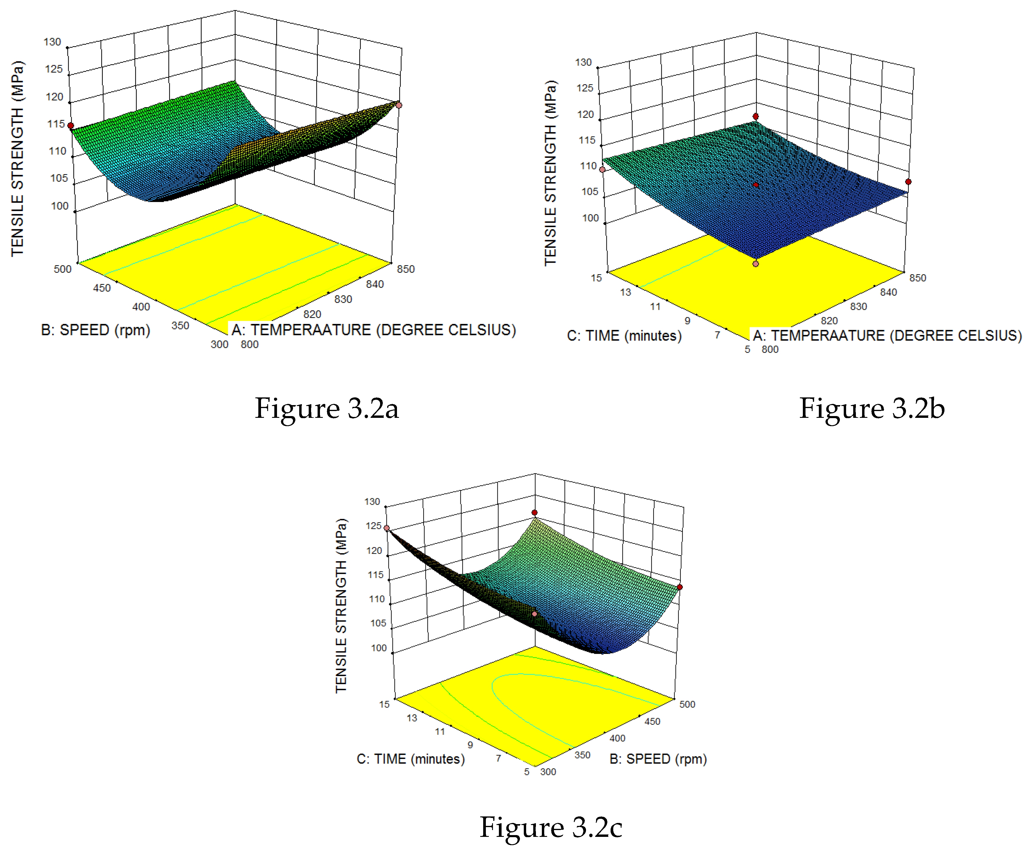
It is clear from Figure 3.2a and 3.2b that tensile strength decreases if speed and temperature increases. From Figure 3.2c it is seen that tensile strength increases with increase in time. Therefore, the combination of control factors for highest tensile strength should consist of minimum speed, minimum temperature and maximum time.

3.3. Optical Micrograph Studies

Figure 3.3 shows the optical micrographs of Al6063 alloy with TiB2 particles It is observed that the fine TiB2 particles (black particles seen in the above image) are distributed evenly throughout the matrix with some traces of intermediate compound, TiAl3, in Figure 3.3.
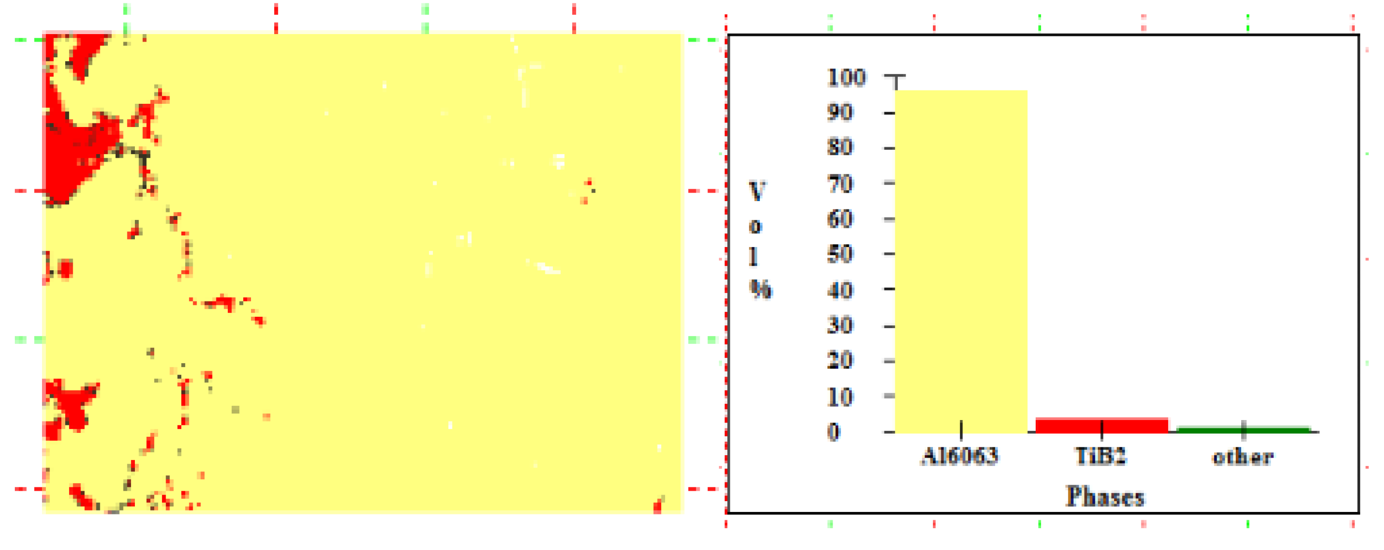
Figure 3.4 shows the phase/volume fraction of composite prepared and it reveals that aluminium occupies 95.67%, TiB2 occupies 3.42% whereas another compound (intermediate TiAl3) occupies 0.91%. This shows that the intermediate compound formation was mostly eliminated as in conventional method of preparation of composites.

3.4. Optimal Solution

The aim is to maximise the hardness and tensile strength. Using the Design expert software, five optimal solutions were developed. The solution with high desirability is chosen. The optimum process parameters chosen is shown in Figure 3.5. The optimum process parameters obtained are temperature of 806.16 °C, time of 15 seconds and speed of 300 rpm.

3.5. Confirmation Test

The confirmation experiments were conducted with the optimal process parameters and the results validated optimal solutions. The percentage of deviation for hardness was 4.68% and for tensile strength is 2.34%.

4. Conclusion

Al-TiB2 composites were successfully prepared using halide salts by varying the stir casting parameters. From the experiments and optimization results, the following conclusions were made. The stir casting parameters were successfully optimised using Box-Benhken design of RSM with the hardness and tensile strength as output responses. ANOVA and 3D surface plots of responses were also analysed. Optical micrograph of the specimens for the optimal solution was analysed and the uniform distribution of reinforcement was revealed. The maximum hardness and tensile strength were obtained at temperature of 806.16 °C, time of 15 seconds and speed of 300 rpm. Al6063 composites are now extensively used in production of lightweight aircraft structures such as ribs and the fuselages.

References

  1. Fei chen, Zonging chen, Fen Mao; TiB2 reinforced aluminium based in situ composites fabricated by stir casting. Materials and Engineering A 625 (2015) 357-368. [CrossRef]
  2. L.LU, M.O.Lai , Y.Su , h.l.Teo , C.F.Feng; In situ TiB2 reinforced Al alloy composites. Scripta materialia 45 (2010) 1017-1023. [CrossRef]
  3. Dr.S.Periyasamy, M. Dr.S.Periyasamy, M.Aravind, D.vivek, Dr.K.S.Amirthagadeswaran; Optimization of surface grinding process parameters for minimum surface roughness in AISI 1080 using response surface methodology. Advanced materials research vols 984-985(2014) 118-123. [CrossRef]
  4. Narendra kumar , Rakesh kumar gowtham , Sunil mohan; In-situ Development of ZrB2 particles and their effect on microstructure and mechanical properties of AA5052 metal matrix composites. Materials and Design. [CrossRef]
  5. R.Keshavamurthy, Sadananda mageri, Ganesh raj, B.Naveen Kumar and K.Vasu; Microstructure and mechanical properties of Al7065-TiB2 In-Situ Composites. Research Journal of Material Sciences. ISSN 2320-6065 Vol 1(10), 6-10, 2013. [CrossRef]
  6. B.Ravi, B. B.Ravi, B.Balu Naik, J.Udhayapraksh; Characterization of Aluminum matrix composites (AA6061/B4C) fabricated by stir casting technique. Materials Today: Proceedings 2 2015 2984-2990. [CrossRef]
  7. Pardeep sharma, Satpal sharma, Dinesh Khanduja; Production and characterization of AA6082-(Si3N4 + Gr) stir cast hybrid composite. Particulate Science and Technology. 0272-6356(print) / 1548-0056(online). [CrossRef]
  8. A.B.Sarmasti, M. A.B.Sarmasti, M.Yazdanirad,M.Nauri Khezrabad,m.Kharbalaie; Effect of alumina particle size and thermal condition of casting on microstructure and mechanical properties of stir cast Al-Al2O3 composites. Materials science and Technology Vol27 No11 1653. [CrossRef]
  9. Ranjith Bauria and, M.K. Surappa; Processing and properties of Al-Li-SiCp Composites. Science and technology of adanced materials 8 2007 494-502. [CrossRef]
  10. Ibrahim Ozbek; A study on re solution heat treatment of AA2618 alumnium alloy. Materials characterisation 58 (2007) 312-317. [CrossRef]
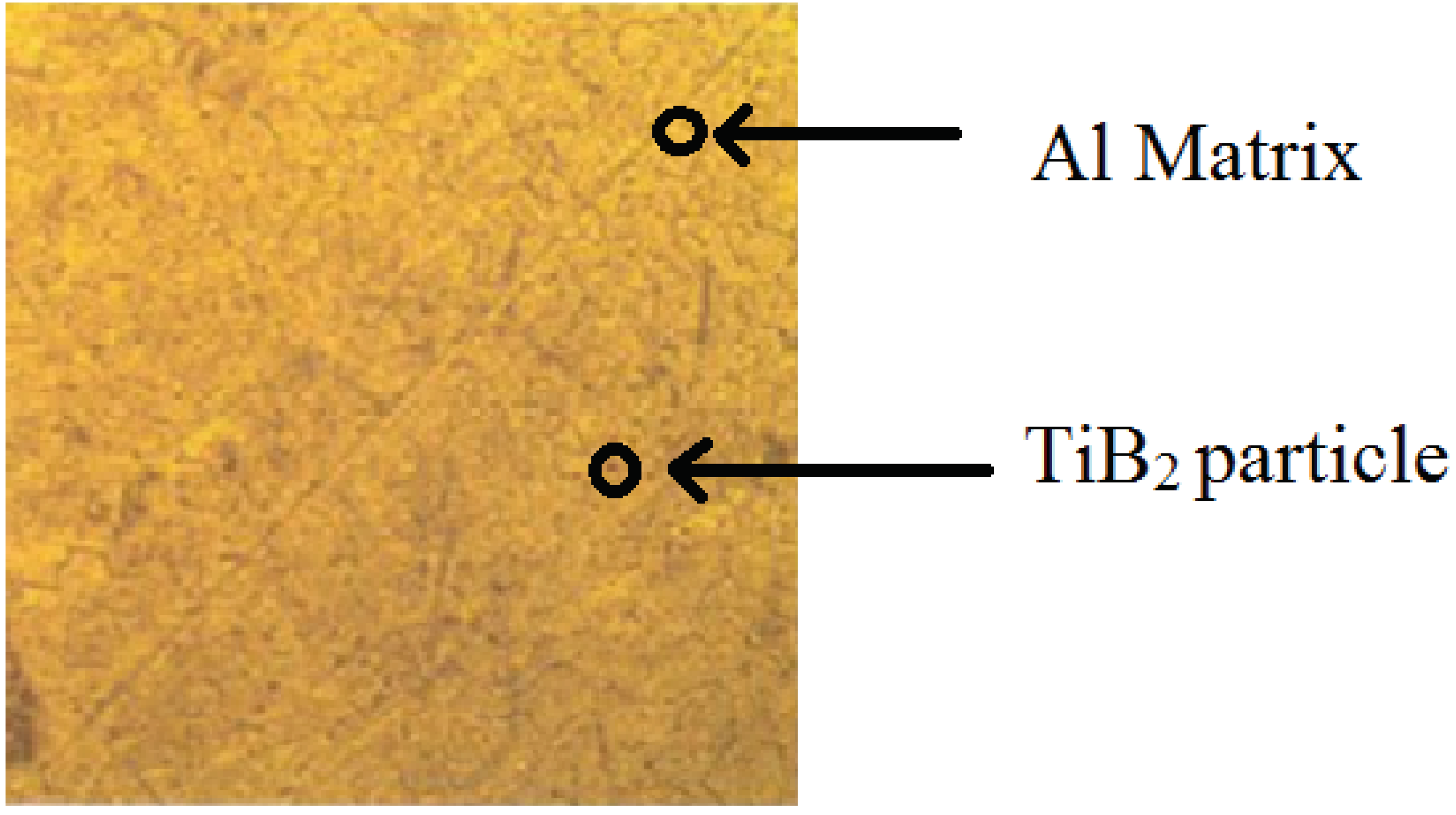
Figure 3.3. Micrograph100 µm.
Preprints 102096 g001
Figure 3.4. phase / volume fraction.
Preprints 102096 g002
Figure 3.5. Optimal solution obtained.
Preprints 102096 g003
Table 2.1. Casting parameters and their levels.
S.No Parameters Level 1 Level 2 Level 3
1 Stirring temperature 750 800 850
2 Stirring Time 5 10 15
3 Stirring Speed 300 400 500
Table 2.2. Design layout.
Factor 1 Factor 2 Factor 3
Run Temperature
°C
Speed
rpm
Time
sec
1 825 300 5
2 850 500 10
3 825 400 10
4 800 500 10
5 800 400 15
6 825 500 15
7 850 400 15
8 850 300 10
9 800 300 10
10 825 300 15
11 825 500 5
12 850 400 5
13 800 400 5
Table 2.3. Fabrication parameters.
Parameters Value
Stirring speed 300-500 rpm
Stirring temperature 800-8500C
Reinforcement preheat temperature 2000C
Stirring time 5-15 minutes
Inert gas Argon
Preheat temperature of mould 4000C
Table 2.4. Response in the design layout.
Factor 1 Factor 2 Factor 3 Output Responses
Run Temperature
°c
Speed
rpm
Time
sec
Hardness
(BHT)
Hardness
(AHT)
Tensile Strength (MPa)
1 825 300 5 33.79 34.47 118.9
2 850 500 10 32.79 33.04 114.0
3 825 400 10 30.49 31.10 107.6
4 800 500 10 32.96 33.62 116.1
5 800 400 15 30.83 31.45 110.7
6 825 500 15 35.31 36.02 121.3
7 850 400 15 31.49 32.12 112.2
8 850 300 10 34.11 34.79 119.8
9 800 300 10 37.74 38.49 124.4
10 825 300 15 43.19 44.05 125.8
11 825 500 5 31.59 32.22 113.9
12 850 400 5 30.56 31.17 108.3
13 800 400 5 30.23 30.84 104.5
Table 3.1. ANOVA (hardness).
Source Sum of Squares df Mean
Square
F-Value Prob > F
Model 165.08 9 18.34 5.90 0.0144
A-SPEED 34.35 1 34.35 11.05 0.0127
B-TEMPERATURE 1.30 1 1.30 0.42 0.5392
C-TIME 26.82 1 26.82 8.63 0.0218
AB 2.34 1 2.34 0.75 0.4140
AC 8.07 1 8.07 2.59 0.1512
BC 0.028 1 0.03 0.01 0.9265
A2 85.30 1 85.30 27.44 0.0012
B2 2.01 1 2.01 0.65 0.4475
C2 4.04 1 4.04 1.30 0.2920
Residual 21.76 7 3.11
Lack of Fit 21.76 3 7.25
Pure Error 0.000 4 0.00
Cor Total 186.84 16
Table 3.2. Tensile strength.
Source Sum of Squares Df Mean
Square
F-Value Prob > F
Model 675.58 9 75.06 23.0 0.0002
A-TEMPERATURE 0.25 1 0.25 0.08 0.7920
B-SPEED 69.62 1 69.62 21.33 0.0024
C-TIME 74.42 1 74.42 22.8 0.0020
AB 1.56 1 1.56 0.48 0.5113
AC 1.32 1 1.32 0.41 0.5447
BC 0.063 1 0.06 0.02 0.8938
A2 0.005921 1 0.01 0.02 0.9672
B2 510.63 1 510.63 156.43 0.0001
C2 7.82 1 7.82 2.39 0.1651
Residual 22.85 7 3.26
Lack of Fit 22.85 3
Cor Total 698.43 16
Table 3.3. Validation results.
Calculated value Experimental value
Hardness 41.7169 39.85
Tensile strength 126.902 124
Disclaimer/Publisher’s Note: The statements, opinions and data contained in all publications are solely those of the individual author(s) and contributor(s) and not of MDPI and/or the editor(s). MDPI and/or the editor(s) disclaim responsibility for any injury to people or property resulting from any ideas, methods, instructions or products referred to in the content.
Copyright: This open access article is published under a Creative Commons CC BY 4.0 license, which permit the free download, distribution, and reuse, provided that the author and preprint are cited in any reuse.
Prerpints.org logo

Preprints.org is a free preprint server supported by MDPI in Basel, Switzerland.

Subscribe

© 2024 MDPI (Basel, Switzerland) unless otherwise stated