Submitted:
25 March 2024
Posted:
26 March 2024
You are already at the latest version
Abstract
Keywords:
1. Introduction
2. Materials and Methods
2.1. Additive Manufacturing of 17-4 PH SS
2.2. The DUPLEX Treatment
2.3. Material Characterization
2.4. Scratch Resistance
3. Results and Discussion
3.1. Chemical and Microstructural Analysis
3.2. Crystalline Phase Identification
3.3. Cross-Sectional Characterization after the DUPLEX Treatment
3.4. Hardness Analysis after the DUPLEX Treatment
3.5. Scratch Resistance of the DUPLEX - 3D Printed 17-4 HP SS
Dynamic scratch testing
Static scratch resistance
4. Conclusions
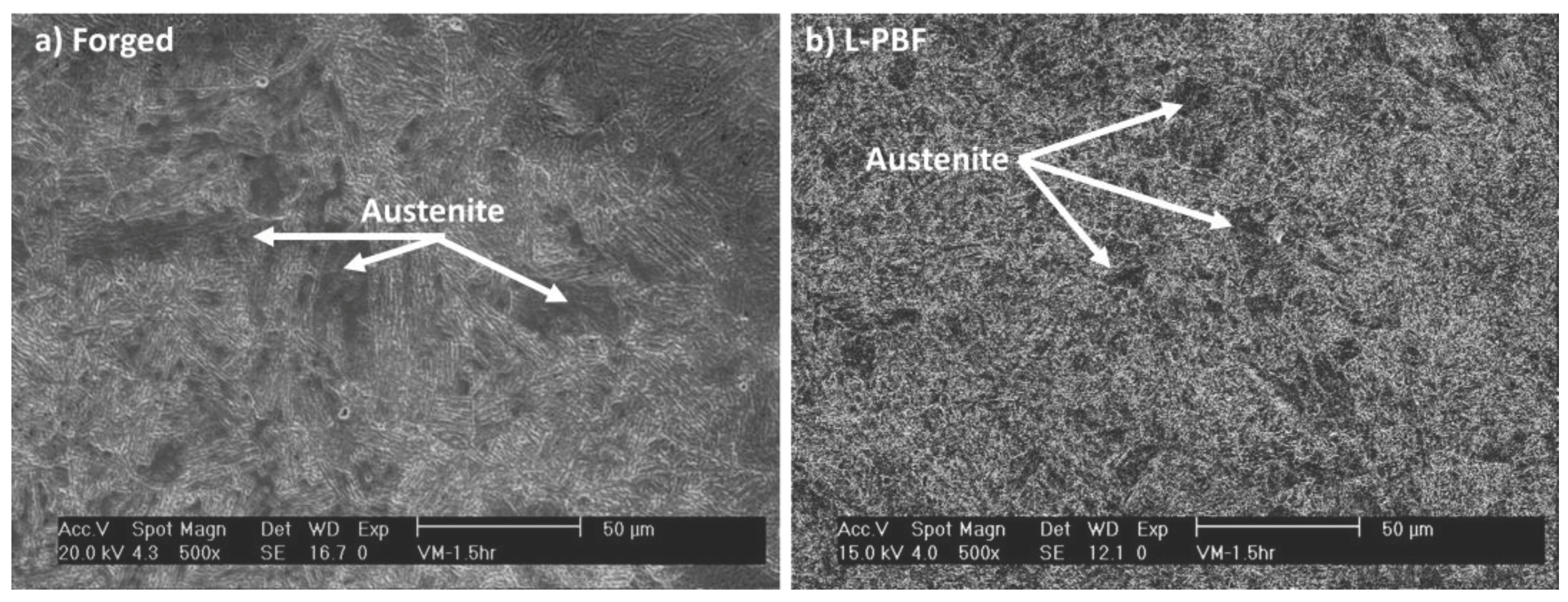
- The heat distribution during the printing process and the thermal history significantly influenced the microstructure of the steel after heat treatment. In the steel obtained by AM, a fine distribution of austenite grains was observed, with small sporadic zones of retained austenite, whereas the forged steel exhibited less refined austenite grains, with the presence of large grains of retained austenite. These differences directly impacted the mechanical properties of the materials, resulting in an observed increase in surface hardness for the forged material.
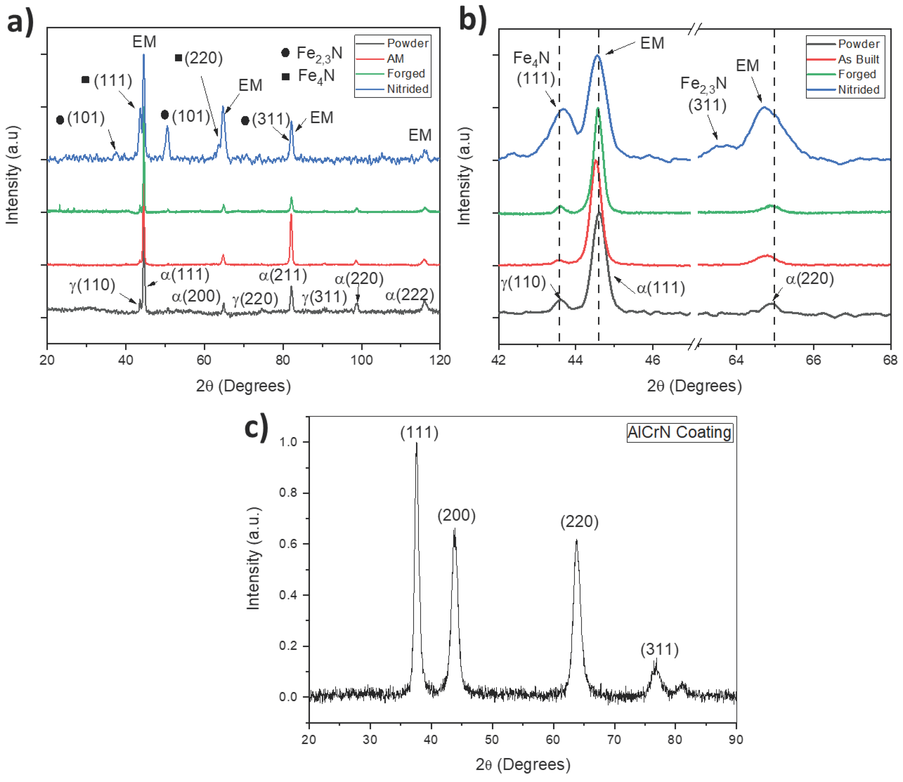
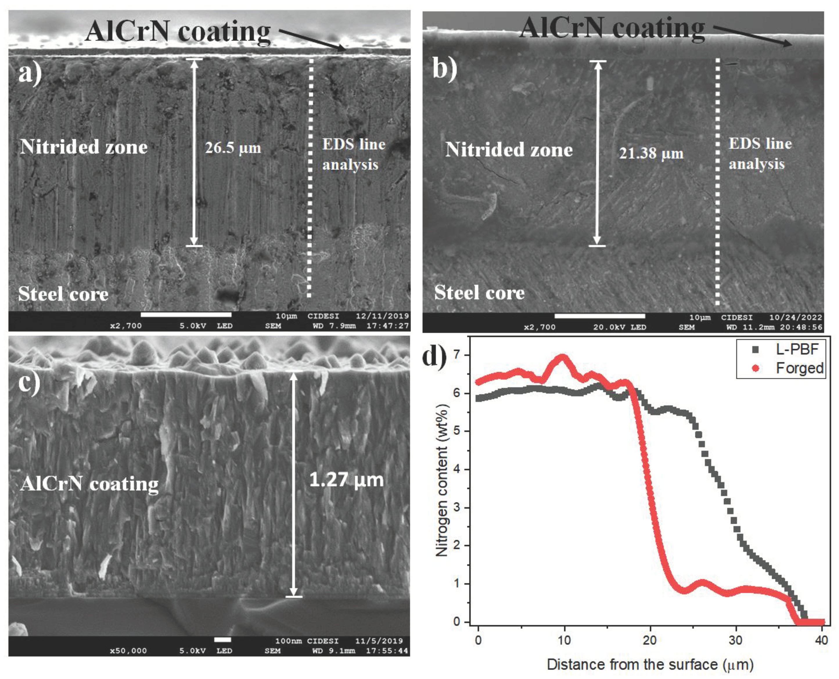
- After DUPLEX treatment, the formation of iron nitrides, the appearance of the expanded phase and the reduction of the gamma phase of iron were observed. For the nitriding conditions used, the appearance of segregated Cr-N phases was not observed, which can increase brittleness and reduce fatigue resistance. The thickness of the nitrided layers was between 21 and 26 um, demonstrating the high efficiency of the low-temperature AEGD-assisted nitriding process. Similarly, the growth of a homogeneous AlCrN layer of 1.27 um thickness was observed, composed of microdroplets, typical of the cathodic evaporation process by electric arc.
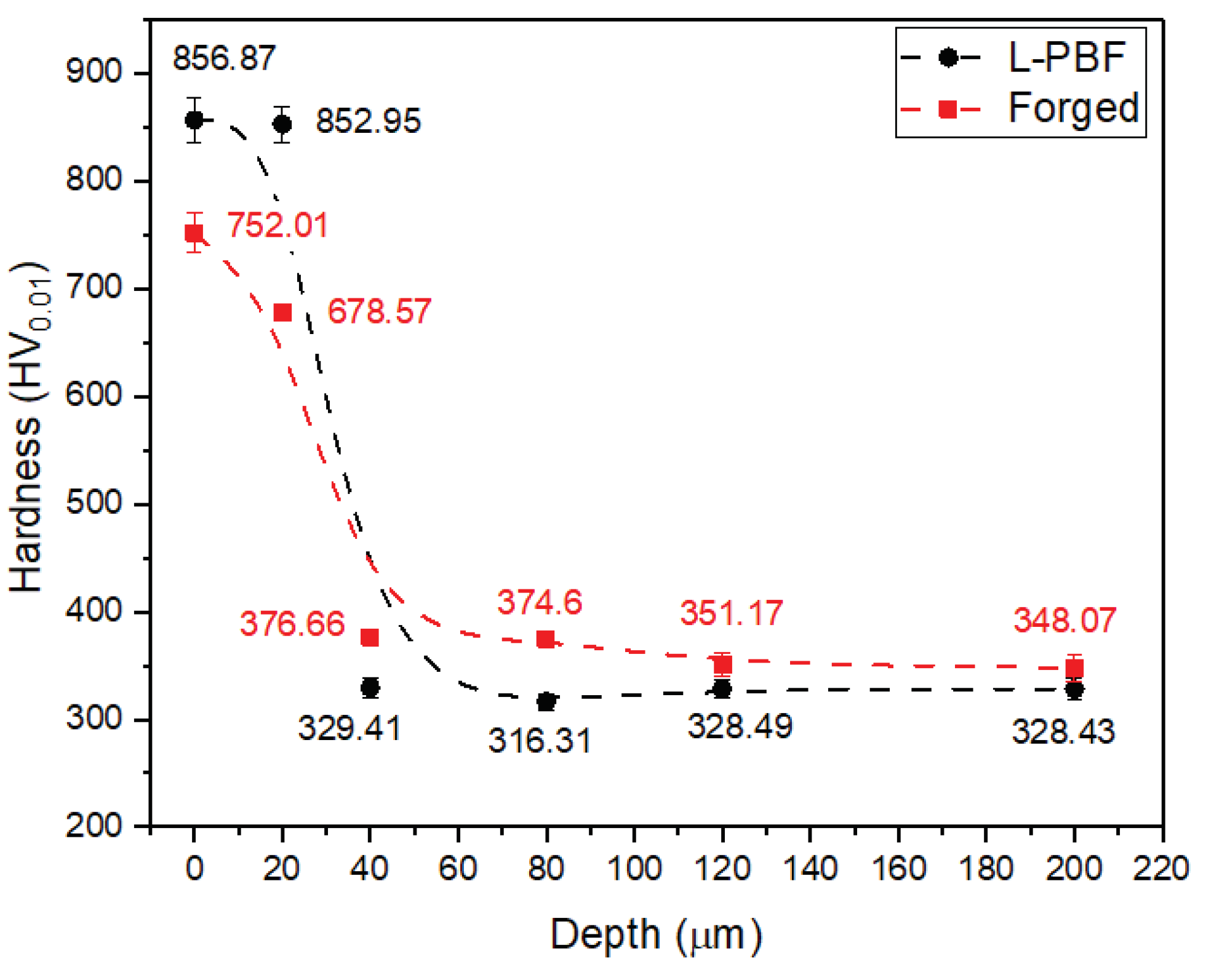
- The creation of a hardness gradient on the surface was observed when producing the DUPLEX treatment. The nitriding process increased the hardness of the heat-treated steel by between 210 and 260%. While the AlCrN coating increased the hardness of the substrate by 830% and 338% with respect to the nitrided surface.
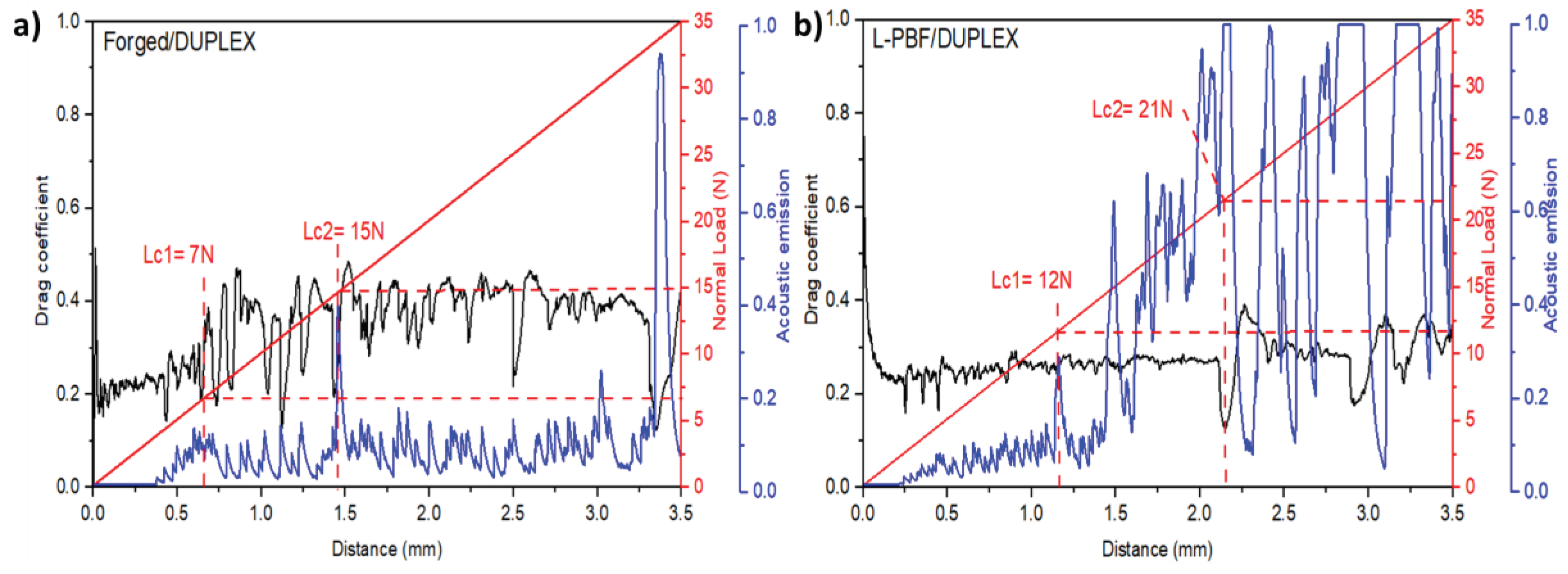
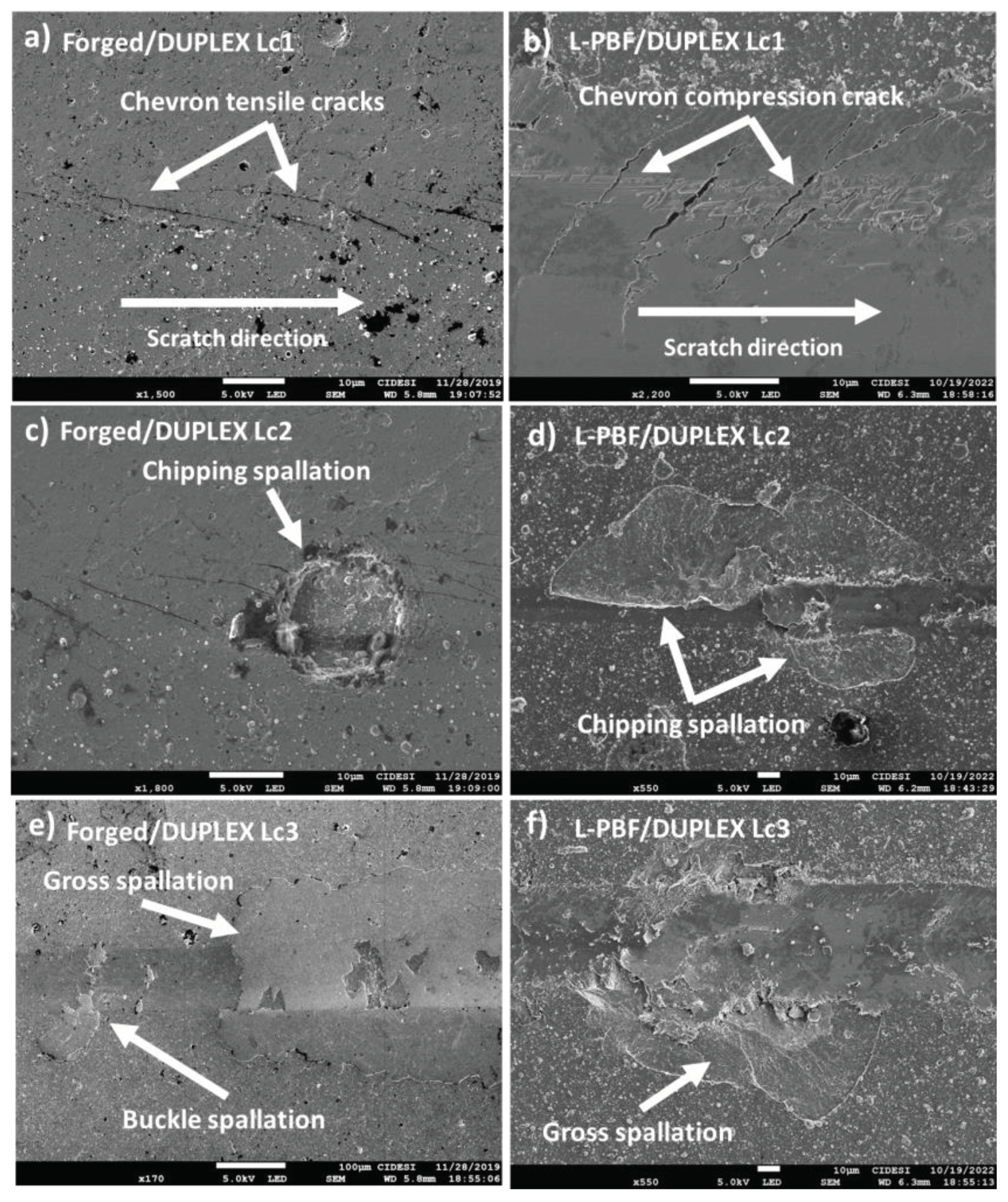
- It was demonstrated that the coatings exhibited acceptable adhesion; however, differences in failure modes were observed, which were related to mechanical properties. The steel manufactured by AM presented cohesive failures related to compression mechanisms and plastic deformation. The forged steel showed failures related to brittle mechanisms induced by tension. However, the adhesive failure patterns were similar for both materials and were characterized by the appearance of chippings, indicated by rounded areas where the coating detached. Finally, at loads greater than 30 N, gross spallation of the coating were observed, attributed to critical plastic deformation of the substrate.
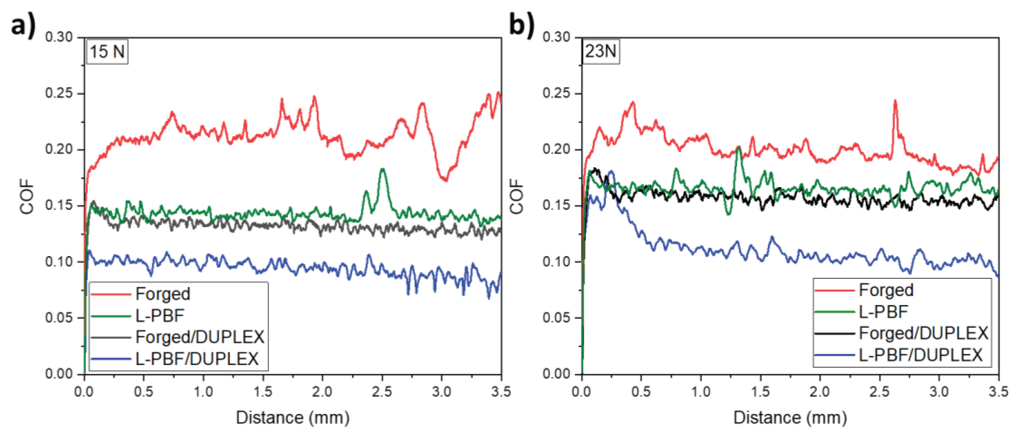
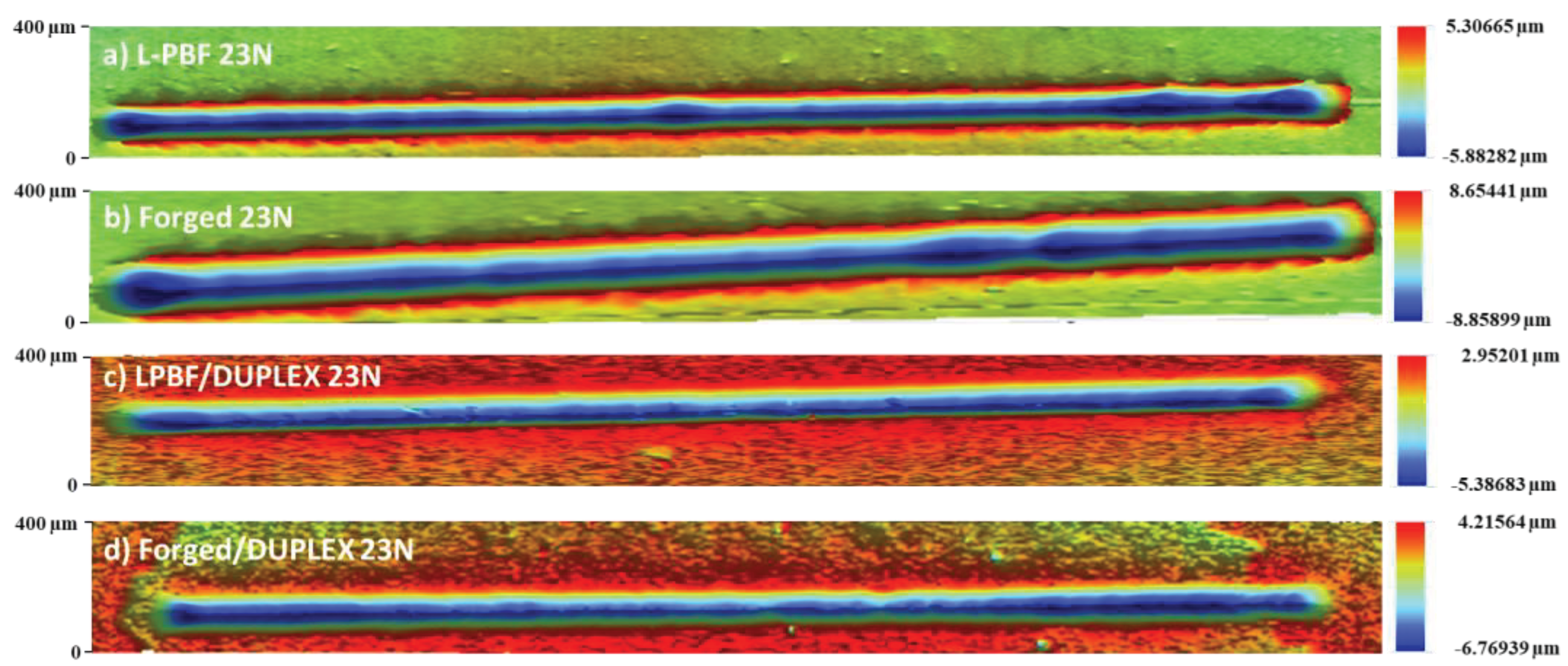
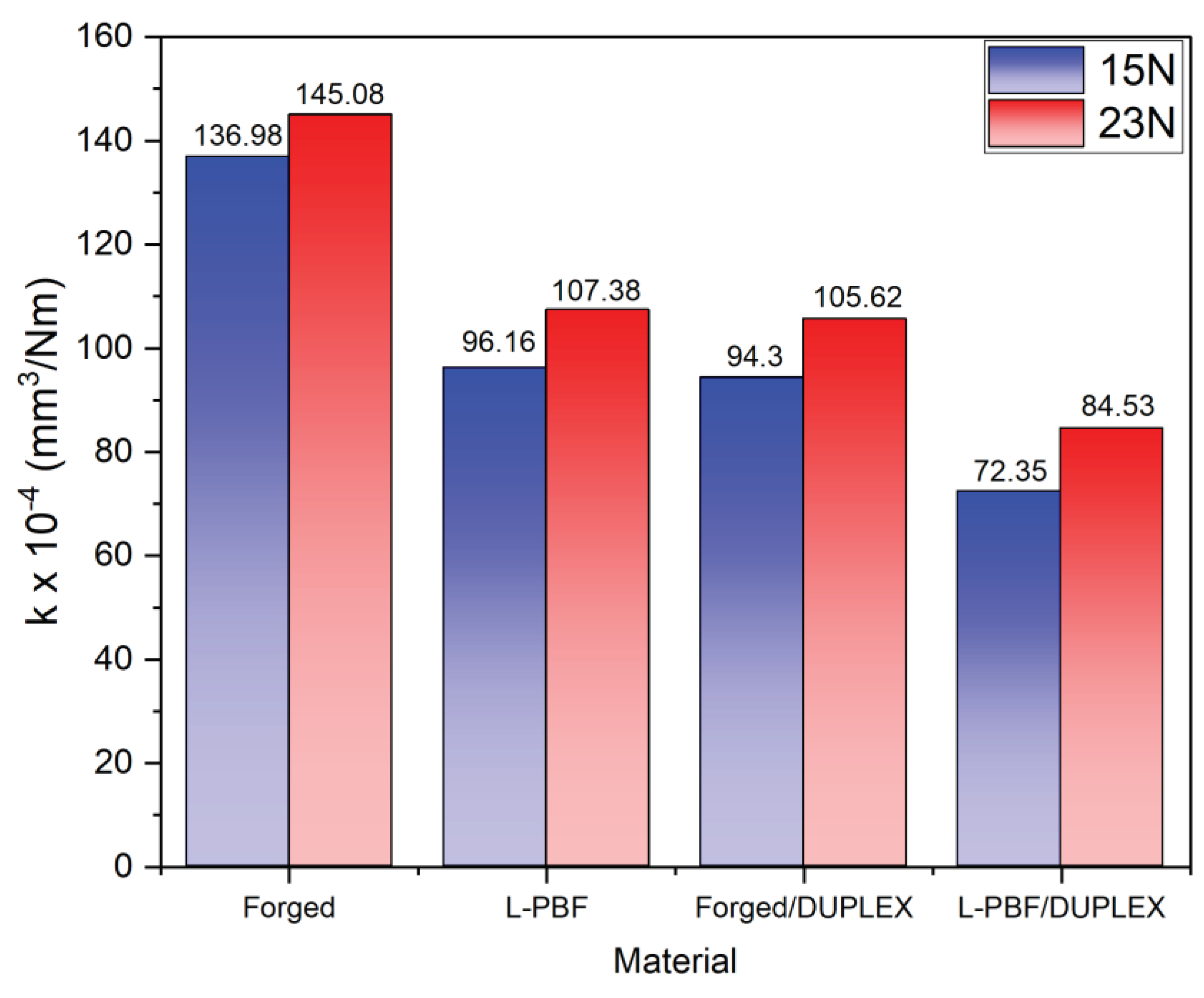
- A reduction in the coefficient of friction (COF) of the materials was observed when performing the DUPLEX treatment. Additionally, instabilities in the COF due to critical plastic deformation were reduced. This produced a decrease in the worn volume and the amount of material accumulated on the edges of the scratch track, which in turn was reflected in the decrease of the wear coefficient between 21 and 31% after the application of the DUPLEX treatment.
Author Contributions
Funding
Data Availability Statement
Acknowledgments
Conflicts of Interest
References
- Yang, L.; Hsu, K.; Baughman, B.; Godfrey, D.; Medina, F.; Menon, M.; Wiener, S. Additive Manufacturing of Metals: The Technology, Materials, Design and Production; Springer Science and Business Media LLC: Dordrecht, GX, Netherlands, 2017. [Google Scholar] [CrossRef]
- Singh, R.; Gupta, A.; Tripathi, O.; Srivastava, S.; Singh, B.; Awasthi, A.; Rajput, S.; Sonia, P.; Singhal, P.; Saxena, K.K. Powder bed fusion process in additive manufacturing: An overview. Mater. Today Proc. 2020, 26, 3058–3070. [Google Scholar] [CrossRef]
- Echeta, I.; Feng, X.; Dutton, B.; Leach, R.; Piano, S. Review of defects in lattice structures manufactured by powder bed fusion. Int. J. Adv. Manuf. Technol. 2019, 106, 2649–2668. [Google Scholar] [CrossRef]
- Adeyemi, A.; Akinlabi, E.T.; Mahamood, R.M. Powder Bed Based Laser Additive Manufacturing Process of Stainless Steel: A Review. Mater. Today: Proc. 2018, 5, 18510–18517. [Google Scholar] [CrossRef]
- Kc, S.; Nezhadfar, P.; Phillips, C.; Kennedy, M.; Shamsaei, N.; Jackson, R. Tribological behavior of 17–4 PH stainless steel fabricated by traditional manufacturing and laser-based additive manufacturing methods. Wear 2019, 440-441, 203100. [Google Scholar] [CrossRef]
- AlMangour, B.; Yang, J.-M. Improving the surface quality and mechanical properties by shot-peening of 17-4 stainless steel fabricated by additive manufacturing. Mater. Des. 2016, 110, 914–924. [Google Scholar] [CrossRef]
- Murayama, M.; Hono, K.; Katayama, Y. Microstructural evolution in a 17-4 PH stainless steel after aging at 400 °C. Met. Mater. Trans. A 1999, 30, 345–353. [Google Scholar] [CrossRef]
- Mirzadeh, H.; Najafizadeh, A. Aging kinetics of 17-4 PH stainless steel. Mater. Chem. Phys. 2009, 116, 119–124. [Google Scholar] [CrossRef]
- Hicho, G.E.; Smith, J.H. Metallurgical evaluation of 17-4 PH stainless steel castings. NISTIR 89-4075. 1989. [Google Scholar] [CrossRef]
- Murr, L.E.; Martinez, E.; Hernandez, J.; Collins, S.; Amato, K.N.; Gaytan, S.M.; Shindo, P.W. Microstructures and properties of 17-4 PH stainless steel fabricated by selective laser melting. J. Mater. Res. Technol. 2012, 1, 167–177. [Google Scholar] [CrossRef]
- Zitelli, C.; Folgarait, P.; Di Schino, A. Laser Powder Bed Fusion of Stainless Steel Grades: A Review. Metals 2019, 9, 731. [Google Scholar] [CrossRef]
- Zhang, Q.; Wu, L.; Zou, H.; Li, B.; Zhang, G.; Sun, J.; Wang, J.; Yao, J. Correlation between microstructural characteristics and cavitation resistance of Stellite-6 coatings on 17-4 PH stainless steel prepared with supersonic laser deposition and laser cladding. J. Alloy. Compd. 2021, 860. [Google Scholar] [CrossRef]
- Mondragón-Rodríguez, G.; Torres-Padilla, N.; Camacho, N.; Espinosa-Arbeláez, D.; de León-Nope, G.; González-Carmona, J.; Alvarado-Orozco, J. Surface modification and tribological behavior of plasma nitrided Inconel 718 manufactured via direct melting laser sintering method. Surf. Coatings Technol. 2020, 387, 125526. [Google Scholar] [CrossRef]
- Tarnowski, M.; Borowski, T.; Skrzypek, S.; Kulikowski, K.; Wierzchoń, T. Shaping the structure and properties of titanium and Ti6Al7Nb titanium alloy in low-temperature plasma nitriding processes. J. Alloy. Compd. 2021, 864, 158896. [Google Scholar] [CrossRef]
- Kaestner, P.; Olfe, J.; He, J.-W.; Rie, K.-T. Improvement in the load-bearing capacity and adhesion of TiC coatings on TiAl6V4 by duplex treatment. Surf. Coatings Technol. 2001, 142-144, 928–933. [Google Scholar] [CrossRef]
- Chang, C.-C.; Duh, J.-G. Duplex coating technique to improve the adhesion and tribological properties of CrAlSiN nanocomposite coating. Surf. Coatings Technol. 2016, 326, 375–381. [Google Scholar] [CrossRef]
- Riazi, H.; Ashrafizadeh, F.; Hosseini, S.R.; Ghomashchi, R.; Liu, R. Characterization of simultaneous aged and plasma nitrided 17-4 PH stainless steel. Mater. Charact. 2017, 133, 33–43. [Google Scholar] [CrossRef]
- Pinedo, C.E.; Larrotta, S.I.V.; Nishikawa, A.S.; Dong, H.; Li, X.-Y.; Magnabosco, R.; Tschiptschin, A.P. Low temperature active screen plasma nitriding of 17–4 PH stainless steel. Surf. Coatings Technol. 2016, 308, 189–194. [Google Scholar] [CrossRef]
- Oliveira, S.D.; Tschiptschin, A.P.; Pinedo, C.E. Simultaneous plasma nitriding and ageing treatments of precipitation hardenable plastic mould steel. Mater. Des. 2007, 28, 1714–1718. [Google Scholar] [CrossRef]
- Dong, H.; Esfandiari, M.; Li, X. On the microstructure and phase identification of plasma nitrided 17-4PH precipitation hardening stainless steel. Surf. Coatings Technol. 2008, 202, 2969–2975. [Google Scholar] [CrossRef]
- Riazi, H.; Ashrafizadeh, F.; Hosseini, S.R.; Ghomashchi, R. Influence of simultaneous aging and plasma nitriding on fatigue performance of 17-4 PH stainless steel. Mater. Sci. Eng. A 2017, 703, 262–269. [Google Scholar] [CrossRef]
- Kochmański, P.; Nowacki, J. Activated gas nitriding of 17-4 PH stainless steel. Surf. Coatings Technol. 2006, 200, 6558–6562. [Google Scholar] [CrossRef]
- Meredith, S.; Zuback, J.; Keist, J.; Palmer, T. Impact of composition on the heat treatment response of additively manufactured 17–4 PH grade stainless steel. Mater. Sci. Eng. A 2018, 738, 44–56. [Google Scholar] [CrossRef]
- Pellizzari, M.; Molinari, A.; Straffelini, G. Thermal fatigue resistance of plasma duplex-treated tool steel. Surf. Coatings Technol. 2001, 142-144, 1109–1115. [Google Scholar] [CrossRef]
- Sanaei, N.; Fatemi, A.; Phan, N. Defect characteristics and analysis of their variability in metal L-PBF additive manufacturing. Mater. Des. 2019, 182, 108091. [Google Scholar] [CrossRef]
- Naim, M.; Chemkhi, M.; Kauffmann, J.; Alhussein, A. Taguchi DoE analysis and characterization of 17-4 PH stainless steel parts produced by material extrusion (MEX) process. Adv. Ind. Manuf. Eng. 2024, 8. [Google Scholar] [CrossRef]
- Vetter, J.; Burgmer, W.; Perry, A.J. Arc-enhanced glow discharge in vacuum arc machines. Surf. Coatings Technol. 1993, 59, 152–155. [Google Scholar] [CrossRef]
- Archard, J.F. Contact and Rubbing of Flat Surfaces. J. Appl. Phys. 1953, 24, 981–988. [Google Scholar] [CrossRef]
- Hu, Z.; Zhu, H.; Zhang, H.; Zeng, X. Experimental investigation on selective laser melting of 17-4PH stainless steel. Opt. Laser Technol. 2017, 87, 17–25. [Google Scholar] [CrossRef]
- Kudzal, A.; McWilliams, B.; Hofmeister, C.; Kellogg, F.; Yu, J.; Taggart-Scarff, J.; Liang, J. Effect of scan pattern on the microstructure and mechanical properties of Powder Bed Fusion additive manufactured 17-4 stainless steel. Mater. Des. 2017, 133, 205–215. [Google Scholar] [CrossRef]
- Sowa, R.; Kowal, A.; Roga, E.; Arabasz, S.; Dziedzic, A.; Dul, I.; Parlinska-Wojtan, M. Influence of double solution treatment on hardness in 17-4 pH steel. Zastita Mater. 2016, 56, 261–268. [Google Scholar] [CrossRef]
- Cheruvathur, S.; Lass, E.A.; Campbell, C.E. Additive Manufacturing of 17-4 PH Stainless Steel: Post-processing Heat Treatment to Achieve Uniform Reproducible Microstructure. JOM 2015, 68, 930–942. [Google Scholar] [CrossRef]
- Yoo, W.D.; Lee, J.H.; Youn, K.T.; Rhyim, Y.M. Study on the Microstructure and Mechanical Properties of 17-4 PH Stainless Steel Depending on Heat Treatment and Aging Time. Solid State Phenom. 2006, 118, 15–20. [Google Scholar] [CrossRef]
- Sun, Y.; Bell, T. Low Temperature Plasma Nitriding Characteristics of Precipitation Hardening Stainless Steel. Surf. Eng. 2003, 19, 331–336. [Google Scholar] [CrossRef]
- Lomello, F.; Sanchette, F.; Schuster, F.; Tabarant, M.; Billard, A. Influence of bias voltage on properties of AlCrN coatings prepared by cathodic arc deposition. Surf. Coatings Technol. 2013, 224, 77–81. [Google Scholar] [CrossRef]
- Tang, J.-F.; Lin, C.-Y.; Yang, F.-C.; Tsai, Y.-J.; Chang, C.-L. Effects of nitrogen-argon flow ratio on the microstructural and mechanical properties of AlCrN coatings prepared using high power impulse magnetron sputtering. Surf. Coatings Technol. 2020, 386, 125484. [Google Scholar] [CrossRef]
- Sabitzer, C.; Paulitsch, J.; Kolozsvári, S.; Rachbauer, R.; Mayrhofer, P. Impact of bias potential and layer arrangement on thermal stability of arc evaporated Al-Cr-N coatings. Thin Solid Films 2016, 610, 26–34. [Google Scholar] [CrossRef]
- Chen, M.; Wu, D.; Chen, W.; Zhang, S. Structural optimisation and electrochemical behaviour of AlCrN coatings. Thin Solid Films 2016, 612, 400–406. [Google Scholar] [CrossRef]
- Le Bourhis, E.; Goudeau, P.; Staia, M.; Carrasquero, E.; Puchi-Cabrera, E. Mechanical properties of hard AlCrN-based coated substrates. Surf. Coatings Technol. 2009, 203, 2961–2968. [Google Scholar] [CrossRef]
- Kumar, T.S.; Jebaraj, A.V. Metallurgical characterization of CrN and AlCrN physical vapour deposition coatings on aluminium alloy AA 6061. Mater. Today: Proc. 2020, 22, 1479–1488. [Google Scholar] [CrossRef]
- Feng, Y.-P.; Zhang, L.; Ke, R.-X.; Wan, Q.-L.; Wang, Z.; Lu, Z.-H. Thermal stability and oxidation behavior of AlTiN, AlCrN and AlCrSiWN coatings. Int. J. Refract. Met. Hard Mater. 2014, 43, 241–249. [Google Scholar] [CrossRef]
- Randall, N.X. The current state-of-the-art in scratch testing of coated systems. Surf. Coatings Technol. 2019, 380, 125092. [Google Scholar] [CrossRef]
- Steinmann, P.; Tardy, Y.; Hintermann, H. Adhesion testing by the scratch test method: The influence of intrinsic and extrinsic parameters on the critical load. Thin Solid Films 1987, 154, 333–349. [Google Scholar] [CrossRef]
- Mo, J.; Zhu, M.; Lei, B.; Leng, Y.; Huang, N. Comparison of tribological behaviours of AlCrN and TiAlN coatings—Deposited by physical vapor deposition. Wear 2007, 263, 1423–1429. [Google Scholar] [CrossRef]
- Kumar, S.; Maity, S.R.; Patnaik, L. Friction and tribological behavior of bare nitrided, TiAlN and AlCrN coated MDC-K hot work tool steel. Ceram. Int. 2020, 46, 17280–17294. [Google Scholar] [CrossRef]
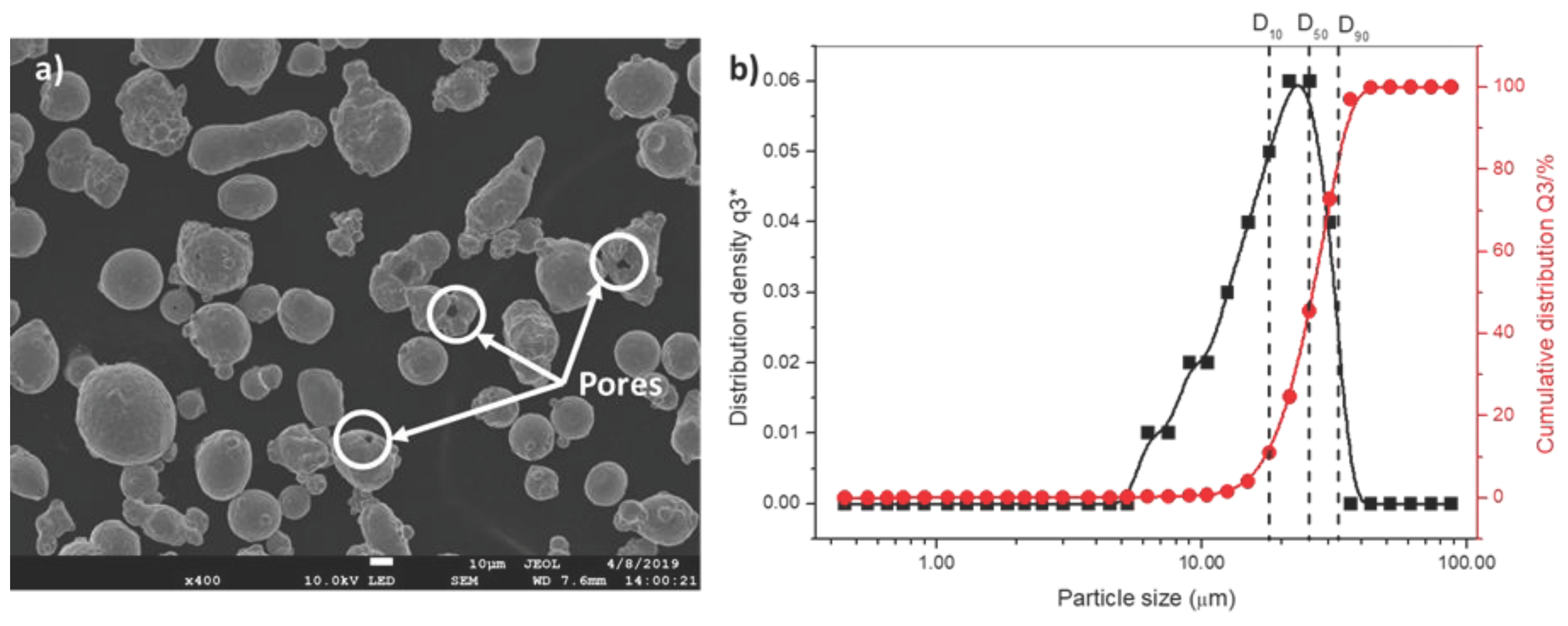
| Element | Initial Powder (wt. %) | Forged(wt. %) | L -PBF(wt. %) | Nominal Composition from Concept laser (wt. %) |
|---|---|---|---|---|
| Si | 0.45 | 0.88 | 0.28 | 1 |
| P | 0.04 | 0.24 | <0.01 | 0.04 |
| S | 0.02 | 0.36 | <0.01 | 0-0.03 |
| Cr | 16.16 | 15.72 | 16.5 | 15-17.5 |
| Mn | 0.8 | 1.34 | 0.98 | 1 |
| Ni | 3.80 | 4.39 | 3.71 | 3-5 |
| Cu | 3.75 | 3.10 | 3.45 | 3-5 |
| Nb | 0.25 | 1.07 | 0.3 | 0.15-0.45 |
| Fe | 69.3 | 72.90 | 69.62 | Balance |
Disclaimer/Publisher’s Note: The statements, opinions and data contained in all publications are solely those of the individual author(s) and contributor(s) and not of MDPI and/or the editor(s). MDPI and/or the editor(s) disclaim responsibility for any injury to people or property resulting from any ideas, methods, instructions or products referred to in the content. |
© 2024 by the authors. Licensee MDPI, Basel, Switzerland. This article is an open access article distributed under the terms and conditions of the Creative Commons Attribution (CC BY) license (http://creativecommons.org/licenses/by/4.0/).


