1. Introduction
In the realm of ultrasonic transducer technology, piezoelectric crystals, ceramics, and polymers materials have long dominated [
1]. In recent years, due to the advancement in microfabrication techniques, the capacitive micromachined ultrasonic transducers (CMUT) have emerged as a competitive technology in this field. This technology is based on the principle of combining capacitors with membranes. The basic element of a CMUT cell is a plate capacitor, one of which is fixed, and while the other is a flexible membrane. It operates both in transmission and reception modes [
2]. In the transmit mode, by superimposing a DC bias with an AC voltage signal, the membranes oscillate. This oscillation generates acoustical waves, which have a typical ultrasonic frequency. The displacement of the membranes can be of the order of (pm) and can be observed using a laser vibrometer. In the reception mode, incident acoustic waves set the membranes into vibration, modulating the overall capacitance of the device. Under DC voltage, the capacitance variation can be sensed through a readout circuit [
3].
CMUTs are often made with materials like silicon, which plays a significant role in the manufacturing process [
4]. Nowadays, the demand for this material is rocketing due to its extensive range of use, the ongoing energy transition led by many governments, and also with the proliferation of connected devices. Consequently, the adoption of a low-tech approach [
5,
6], prioritizing simplicity, accessibility and lower-energy manufacturing processes, is becoming increasingly crucial for managing the environmental resources of our planet.
This paper introduces the design of a low-tech CMUT followed by a comparison between finite element simulation results and experimental measurements of the displacement and eigenfrequency.
The paper is structured as follows : Section.1 deals with a brief introduction of the CMUT device. Section.2 details the design of the device. Section.3 focuses on finite element simulation. Section.4 covers experimental measurements. The paper concludes with Section.5.
2. Realization of a Low-Tech CMUT
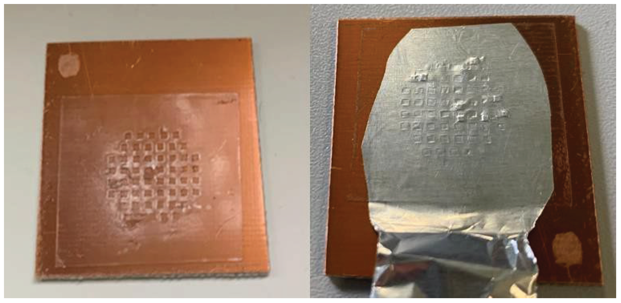
Figure 1 illustrates the materials and fabrication steps of the CMUT. A copper plate, covered with a thin insulating layer, serves as the fixed bottom electrode and defines the device's inertia by being a fixed part. Subsequently, a double-sided adhesive layer, 20µm thick and assimilated to polypropylene, is mechanically cut to create square cavities and applied to the copper plate. Next, a 10µm layer of aluminum foil is attached on top of the adhesive to form the top electrode. When considering the materials and manufacturing process employed, the environmental impact of this device is limited [
5].
It is notable that the prototype has larger dimensions compared to industrial CMUTs, resulting in an expected lower frequency behavior.
3. Finite Element Simulation on COMSOL Multiphysics
COMSOL Multiphysics is a versatile tool to model the comprehensive functionality of the proposed transducer, including various physics studies [
2,
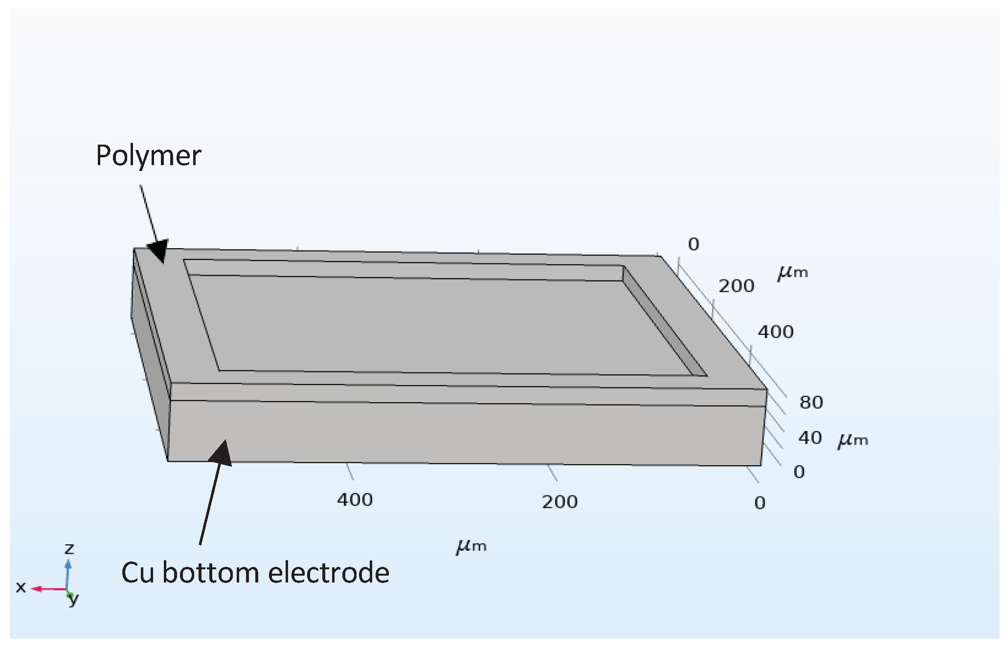
7]. This work focuses on the fundamental analysis of the basic element of a CMUT cell, where Solid Mechanics module of Structural Mechanics Physics study and Electrostatics module of AC/DC Physics study were used to define the boundary conditions. The cell is operating in out-of-plane mode and all edges are kept on fixed constraints as shown in
Figure 2. A 235 VDC Bias along with 10 VAC was superimposed on the top membrane. The bottom membrane was kept at ground.
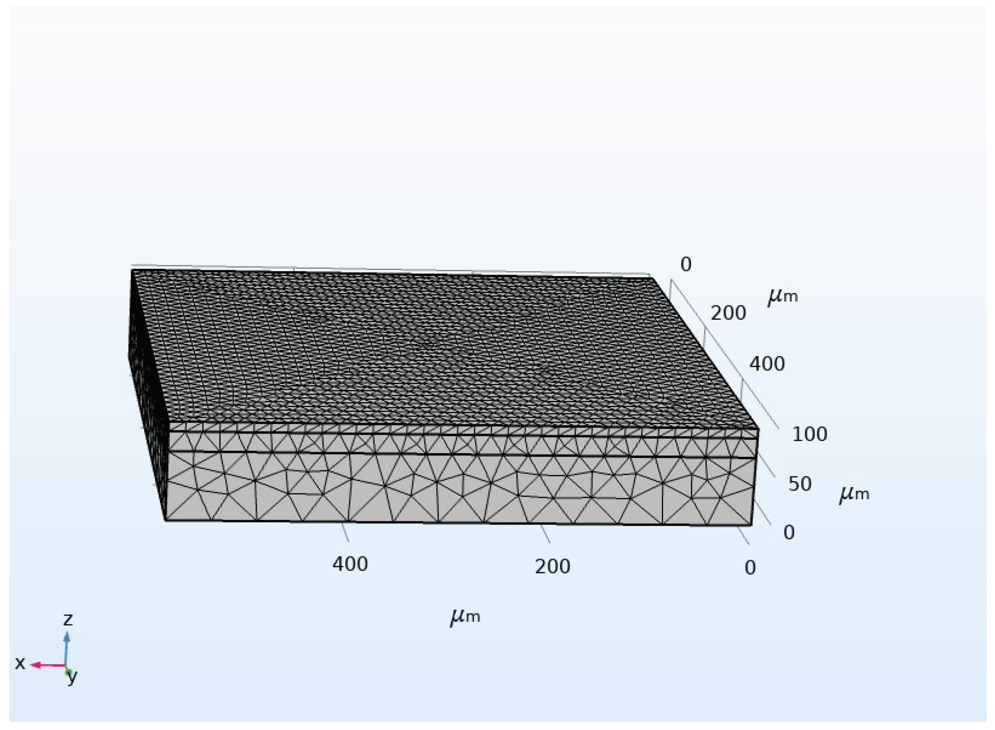
Subsequently, a free tetrahedral mesh of fine size was created for finite element method (FEM) simulations, as shown in
Figure 3. Two studies are conducted simultaneously: a stationary study to examine displacement and mechanical stresses, and a second study in the frequency domain to extract the eigenfrequency of the membrane. In addition to the intrinsic constants for each material preloaded by the software, parameters added to the software are outlined in Table 1.
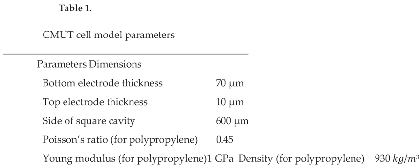
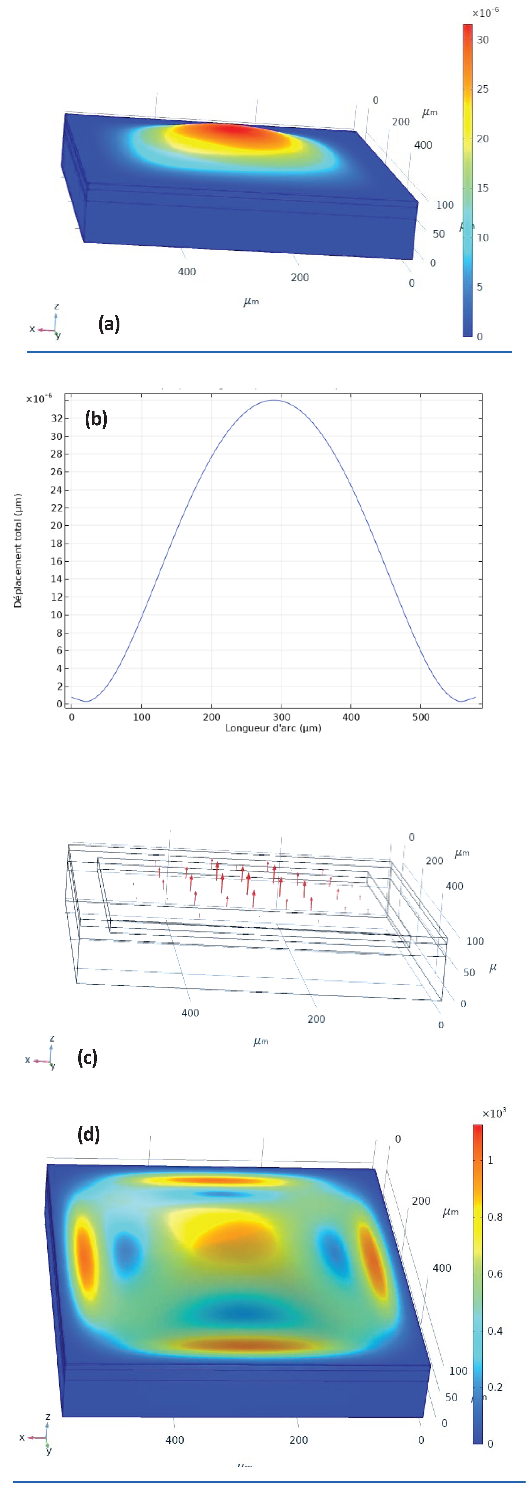
Figure 4. Simulation results: (a) 3D image of “out- of-plane” displacement, (b) membrane deflection as a function of side distance, (c) displacement field arrows when the alternating potential across the CMUT is positive
Figure 4 depicts simulation results, offering a comprehensive view of the CMUT's mechanical behavior. The 3D scan showing displacement intensity, provides valuable insights into the distribution of deformation and its maximum zone with a first mode at the eigenfrequency of 80 210 Hz.
Figure 4.b deals with the deflection curve along the line through the midpoint of two parallel sides. This representation confirms the results from
Figure 4.a by showing a displacement peak of 34 pm, underscoring that the center of the cavity experiences the most significant deflection.
Figure 4.c shows displacement field arrows when the alternating potential across the CMUT is positive. This induces an electrostatic force on the membrane, causing its deformation in that direction.
As for
Figure 4.d, it displays the Von Mises stress on a vibrating membrane. This mechanical parameter represents the applied force normalized to the surface area. Examining this measure is crucial for analyzing material resistance to deformations and estimating the likelihood of material failure. In this case, the stress is notably intense at the edges of the cavity compared to the rest of the surface. However, a value of 10
3 𝑁/𝑚² remains relatively low compared to the breaking thresholds of aluminum foil, which is 70.10
6N/m
2 [
8].
4. Experimental Measurements
4.1. Electrical Characterization
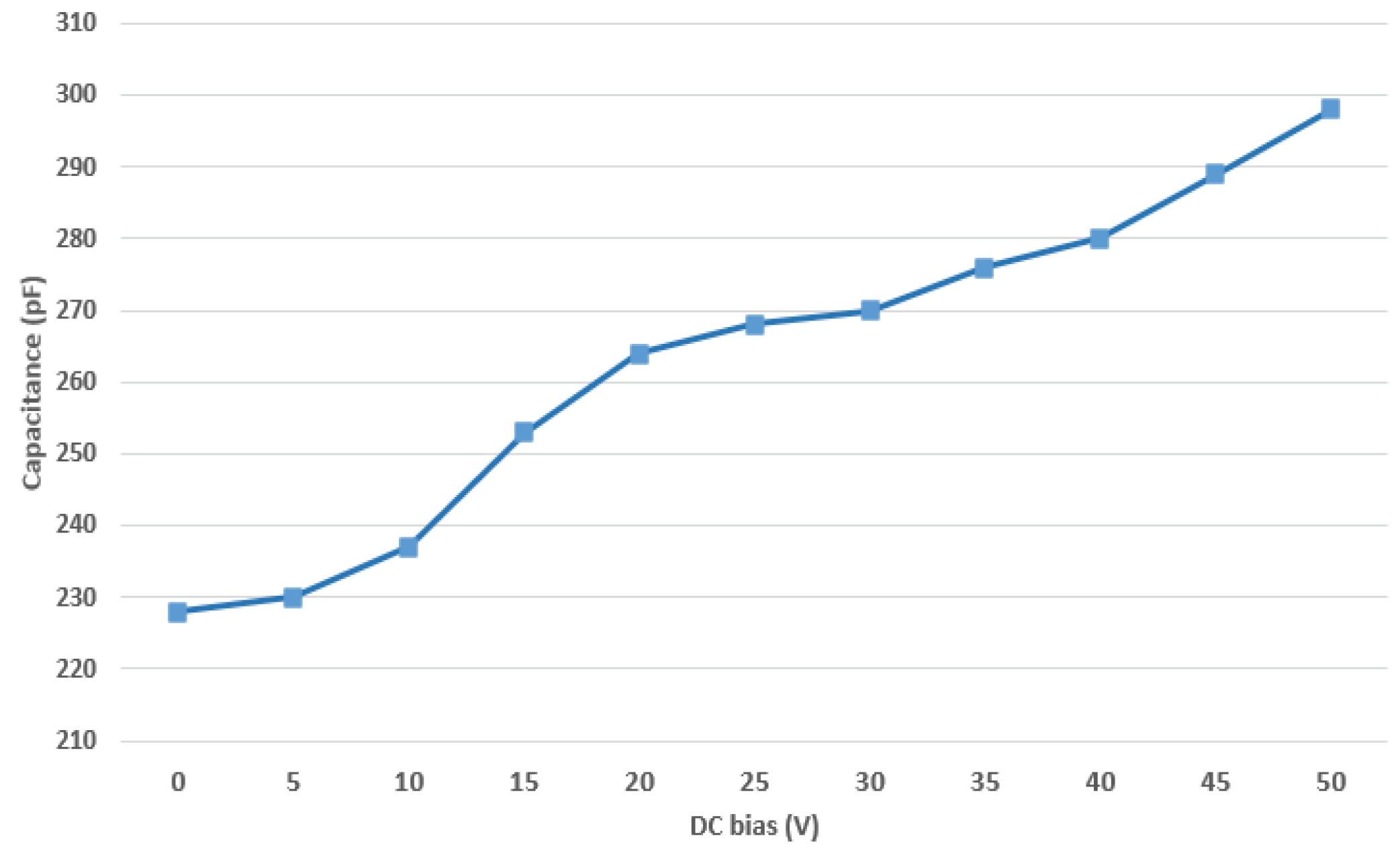
In addition to the simulation, experimental measurements were conducted to validate the performance of the low-tech CMUT. The first procedure involved supplying the device with DC bias without applying AC voltage, then the overall capacitance is measured for each Vdc using a multimeter, as illustrated in
Figure 5.
The initial capacitance value of the CMUT is nearly 230 pF. As the DC bias is incremented, it causes a rise in the electric field 𝐸 within the structure. This electric field induces an electrostatic force, leading to an attraction of additional charges between the two electrodes. Once the pull-in voltage is passed (not reached in this measurement) the capacitance value is expected to stabilize.
4.2. Mechanical characterization
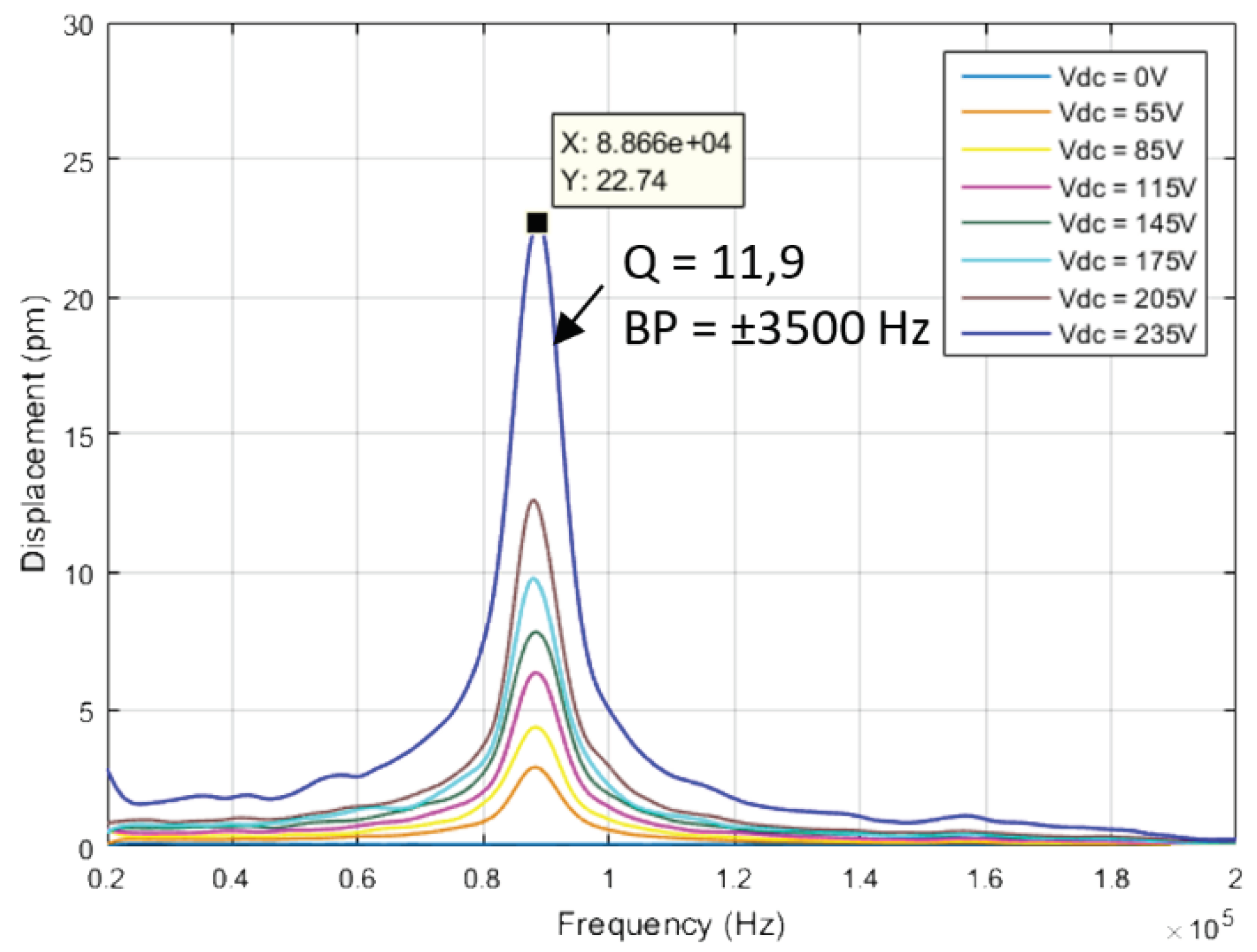
The second experiment aims to characterize the mechanical behavior of the CMUT. For this purpose, a laser vibrometer was employed to measure the out-of-plane displacement when the device is subjected to a 10Vpp Chirp signal while varying DC Bias from 0 to 235 V. Audible acoustic waves generated by the CMUT can be perceived from this actuation. After acquiring the displacement curve, MATLAB software was for post-processing operations such as filtering and fitting the data points.
Figure 6 presents the results.
The displacement response of the CMUT is amplified as the DC bias increases . At 235V, dynamic resonance mode had an out-of-plane amplitude exceeding 20 pm. The quality factor
Q = 11.9 reflects the ability to operate effectively within a specific frequency range, in this case, ±3500 𝐻𝑧 centered around the central frequency of 88.6 kHz.
The resonance frequency and the maximum displacement obtained in the simulation (80.21 kHz; 34 pm) is in the same order of magnitude as the experimental value (88.6 kHz; 22 pm).
However, the observed disparity could arise from factors like fabrication tolerances, boundary condition differences, environmental conditions influences.
5. Conclusion and Perspectives
In this work, a low-tech CMUT was fabricated and characterized, highlighting a sustainable approach using lower environmental footprint materials and manufacturing processes. The fabrication involved a copper plate, polymer-based adhesive, and aluminum foil. Comprehensive characterization, involving both simulation and experimental measurements, has been demonstrated. Considering the larger dimensions, the CMUT demonstrated an electromechanical behavior, with an eigenfrequency and displacement exceeding respectively 80 kHz and 20 pm.
These transducers hold potential for various applications including ultrasonic actuation and energy harvesting, thanks to their low material costs compared to any other fabrication techniques. The simplicity, biocompatibility and low environmental impact can unlock the full potential of CMUT low-tech. However, these transducers may not be directly integrated into industrial applications, they serve as excellent candidates for educational purposes, providing hands-on experience with a technology similar to high-performance silicon-based implementations. Thanks to these low-cost MUTs, simulation results could be verified experimentally using tools that can be found in any fablab.
Acknowledgments
Authors would like to thank the Certem: “Centre d'Études et de Recherches Technologiques en Microélectronique” for providing the equipment to measure the electromechanical properties of all micromachined systems.
References
- GOYAL, Rahul et YADAV, Divya Mohan. Design and simulation of a mems-based capacitive micro-machined ultrasonic transducer for viscosity sensing applications. Centre for Nanoscience and Engineering, Indian Institute of Science, 2019.
- Ray, A.; Chandel, V.; Taiwade, K.; Bamne, J.; Bhargav, A.; Haque, F.Z. Design and analysis of CMUT device using COMSOL for Radio frequency applications. Mater. Today: Proc. 2022, 65, 2602–2605. [Google Scholar] [CrossRef]
- A Anbalagan, S.; Uma, G.; Umapathy, M. Modeling and simulation of Capacitive Micromachined Ultrasonic Transducer (CMUT). J. Physics: Conf. Ser. 2006, 34, 595–600. [Google Scholar] [CrossRef]
- Wang, Y.-H.; Song, P.; Li, X.; Ru, C.; Ferrari, G.; Balasubramanian, P.; Amabili, M.; Sun, Y.; Liu, X. A Paper-Based Piezoelectric Accelerometer. Micromachines 2018, 9, 19. [Google Scholar] [CrossRef] [PubMed]
- Lemaire, E.; Moser, R.; Borsa, C.; Shea, H.; Briand, D. Green Paper-based Piezoelectric Material for Sensors and Actuators. Procedia Eng. 2015, 120, 360–363. [Google Scholar] [CrossRef]
- E. Lemaire et al., "Fast fabrication process of low environmental impact," 4 Novembre 2015.
- Ravi, "Modeling and Simulation of Dual Application Capacitive MEMS Sensor," 2014.
- SCHWEITZER, S.A. S, "FICHE TECHNIQUE PAPIER ALUMINIUM CUTTER BOX," 04,2021.
- Phan, H.-P.; Dao, D.V.; Dinh, T.; Brooke, H.; Qamar, A.; Nguyen, N.-T.; Zhu, Y. Graphite-on-paper based tactile sensors using plastic laminating technique. 2015 28th IEEE International Conference on Micro Electro Mechanical Systems (MEMS). LOCATION OF CONFERENCE, PortugalDATE OF CONFERENCE; pp. 825–828.
- Liu, X.; Mwangi, M.; Li, X.; O'Brien, M.; Whitesides, G.M. Paper-based piezoresistive MEMS sensors. Lab a Chip 2011, 11, 2189–2196. [Google Scholar] [CrossRef] [PubMed]
|
Disclaimer/Publisher’s Note: The statements, opinions and data contained in all publications are solely those of the individual author(s) and contributor(s) and not of MDPI and/or the editor(s). MDPI and/or the editor(s) disclaim responsibility for any injury to people or property resulting from any ideas, methods, instructions or products referred to in the content. |
© 2024 by the authors. Licensee MDPI, Basel, Switzerland. This article is an open access article distributed under the terms and conditions of the Creative Commons Attribution (CC BY) license (https://creativecommons.org/licenses/by/4.0/).

