Submitted:
23 March 2024
Posted:
26 March 2024
You are already at the latest version
Abstract
Keywords:
1. Introduction
2. Materials and Methods
3. Results
3.1. The Magnitude of the Resulting Hydraulic Oil Pressure Is Affected by the Different Values of the Hydraulic Oil Pressures in the Hydraulic Cylinders and the Pressure in the Supply Pipe
3.2. The Magnitude of the Resulting Pressure of the Hydraulic Oil Affected by the Change in the Different Magnitudes of the Pulling Forces in the Ropes
4. Discussion
5. Conclusions
Author Contributions
Funding
Data Availability Statement
Conflicts of Interest
References
- DIN EN 81-20: Safety rules for the construction and installation of lifts – Lifts for the transport of persons and goods – Part 20: Passenger and goods passenger lifts (In Czech: Bezpečnostní předpisy pro konstrukci a montáž výtahů – Výtahy pro dopravu osob a nákladů – Část 20: Výtahy pro dopravu osob a osob a nákladů). Available online: https://www.technickenormy.cz/din-en-81-20-safety-rules-for-the-construction-and-installation-of-lifts-lifts-for-the-transport-of-persons-and-goods-part-20-passenger-and-goods-passenger-lifts-7/ (accessed on 1 June 2020).
- EN 12385-5:2002: Steel wire ropes - Safety - Part 5: Stranded ropes for lifts (In Czech: Ocelová drátěná lana - Bezpečnost - Část 5: Pramenná lana pro výtahy). Available online: https://www.technickenormy.cz/csn-en-12385-5-ocelova-dratena-lana-bezpecnost-cast-5-pramenna-lana-pro-vytahy-3/ (accessed on 1 November 2021).
- Směrnice evropského parlamentu a rady 2000/9/ES. Available online: 32000L0009_001cs 3..10 (europa.eu) (accessed on 20 March 2020). Available online:.
- Zákon č. 22/1997 Sb.: Zákon o technických požadavcích na výrobky a o změně a doplnění některých zákonů. Available online: https://www.zakonyprolidi.cz/cs/1997-22 (accessed on 27 February 1997).
- Nařízení vlády č. 122/2016 Sb.: Nařízení vlády o posuzování shody výtahů a jejich bezpečnostních komponent. Available online: https://www.zakonyprolidi.cz/cs/2016-122 (accessed on 18 April 2016). Available online:.
- oralkar, S. Traction in Elevators. Elevator World India 2009, pp. 84-88.
- Yuda, S. M.; Pane, M. and Elyes, F. Design of Top Traction Elevator in Building 6 Floor. VANOS Journal of Mechanical Engineering Educatio 2021, 6(2), pp. 107-115.
- Soyaslan, M.; Avsar, Y.; Fenercioglu, A. and Sarihan, F. Design and production of belt drive elevator traction machine: modelling of double side belt system. Politeknik Dergisi 2023, 1-1.
- Annett, F. A. Elevators: electric and electrohydraulic elevators, escalators, moving sidewalks and ramps. 1960.
- Wrap traction overhead type elevator Available online: https://crownelevators.in/images/ropes/elevator-cable-setups.png.
- Hrabovsky, L. and Maslaric, M. Device designed for detection and setting the required tensile force in ropes. Advances in Science and Technology. Research Journal 2018, 12(1), pp. 200-206. [CrossRef]
- Hrabovsky, L. and Michalik, P. A tension equalizer in lift carrying ropes. Advances in Science and Technology. Research Journal 2017, 11(4). [CrossRef]
- Mingxiang, H.; Dequan, C.; Lizhi, P.; Longbin, Z. and Bo, T. Design of Monitoring Sensors for Rope Force in Assembling Tower with Inside Suspension Pole. In 2021 International Conference on Advanced Electrical Equipment and Reliable Operation (AEERO) (pp. 1-6). IEEE, 2021.
- Barnes, M and Rhiner, M. Constructional Stretch and Hoist-Rope Tension. Available online: https://elevatorbooks.com/wp-content/uploads/2019/02/EW0712.pdf (accessed on 20 March 2024).
- Kim, D. B. and Kim, G. S. A Study on the Development of an Elevator Rope Tension Automatic Equalizer. Journal of the Korean Society of Manufacturing Process Engineers 2020, 19(5), pp. 60-66. [CrossRef]
- Cvik, K.; Golasowski, J. and Hinner, V. Experience with operation of multi-rope hoisting equipment without any device for automatic equalization of tension in hoisting ropes. Uhli;(Czechoslovakia) 1989, 37(8).
- Zhang, X. and Jin, H. Design of strain tension sensor of steel wire rope used in the coal mine, in Proceedings of the Seventh International Symposium on Precision Mechanical Measurements, p. 99030C, Xiamen, China, January 2016.
- Liu, P; Zhang, X. Huang, Y. K. and Rong, J. X. The analysis of wire rope tension sensor elastic body based on solidworks, Advanced Materials Research 2012, vol. 591–593, pp. 1603–1606. [CrossRef]
- Singh, M. K.; Mahto, A.; Thakur, R. N. and Sinha, A. Failure analysis of wire rope used for hoisting in mining: a case study,” Journal of Failure Analysis and Prevention 2007, vol. 7, no. 2, pp. 87–91. [CrossRef]
- Jin, H. W. and Zhang, X. Design of dynamic tension detection system of multi-hoisting wire rope. Applied Mechanics and Materials 2012, 201, 565-568. [CrossRef]
- Lei, G.; Xu, G.; Zhang, X.; Zhang, Y.; Song, Z. and Xu, W. Study on dynamic monitoring of wire rope tension based on the particle damping sensor. Sensors 2019, 19(2), 388. [CrossRef]
- Hrabovsky, L. Tension force equalizer in a rope system using a proximity sensor. Zeszyty Naukowe. Transport/Politechnika Śląska 2021. [CrossRef]
- Yao, M.; Jin, Y.; Zhao, M. and Xu, S. Research and Application of Heavy-Equipment Parachute Rope Tension Sensor. Journal of Sensors, 2018, 1-10. [CrossRef]
- Zhao, M.; Tian, X. H.; Zhang, R. Y. and Wu, L. L. A wireless passive tension sensor. In Proceedings of the 16th International Conference on Mechatronics-Mechatronika 2014 (pp. 473-476). IEEE.
- Xu, G.; Da, J.; Zhang, X.; Han, M. and Xia, T. A novel tension monitoring device of multi-rope friction hoister by using acoustic filtering sensor. Journal of Vibroengineering 2016, 18(8), 5537-5552. [CrossRef]
- Hrabovsky, L. and Borovsky, D. Laboratory device for checking the functionality of the elevator rope sensors. Management Systems in Production Engineering 2021, 29.1, pp. 59-64. [CrossRef]
- Lei, G.; Xu, G.; Zhang, X. and Tian, B. Study on dynamic characteristics and compensation of wire rope tension based on oil pressure sensor. Advances in Mechanical Engineering 2019, 11(3), 1687814019836024. [CrossRef]
- Mitsantisuk, C.; Ohishi, K. and Katsura, S. Control of interaction force of twin direct-drive motor system using variable wire rope tension with multisensor integration,” IEEE Transactions on Industrial Electronics 2012, vol. 59, no. 1, pp. 498–510. [CrossRef]
- Daifuku, S.; Li, B.; Yamaguchi, Y.; Nagatoshi, M. and Imado, K. Development of tension meter for wire rope and lashing belt,” Journal of Mechanical Systems for Transportation and Logistics 2013, vol. 6, no. 1, pp. 65–72.
- Jin, H. W. and Zhang, X. Design of dynamic tension detection system of multi-hoisting wire rope. Applied Mechanics and Materials 2012, 201, 565-568. [CrossRef]
- Liu, S.; Zeng, X.; Ni, M.; Liu, Z. and Mo, L. Tension measurement for wire ropes based on magneto-elastic effect. In 2018 Prognostics and System Health Management Conference (PHM-Chongqing) 2018, pp. 50-56. IEEE.
- Konstantinov, M. Y.; Kiseleva, M. V. and Novikov, A. F. Equalizing forces in ropes of a multi-rope hoisting system. Ugol'Ukr.;(Ukrainian SSR) 1981, 5.
- Ruční olejová pumpa jednočinná s nádrží 3L. Available online: https://www.kardanka.cz/rucni-olej-pumpa-jednocinna-s-nadrzi-3l-23987 (accessed on 20 January 2023).
- Standardní dvoučinný hydraulický válec 32/20/50. Available online: https://www.kardanka.cz/standardni-dvoucinny-hydraulicky-valec-32/20/50-205-mm-35722 (accessed on 11 August 2023).
- Šestipramenné lano 6x19M-WSC. Available online: https://www.lana-retezy.cz/sestipramenna-lana/sestipramenne-lano-6x19m-wsc/ (accessed on 26 December 2022). Available online:.
- ČSN EN 12385-4: Steel wire ropes - Safety - Part 4: Stranded ropes for general lifting applications (In Czech: Ocelová drátěná lana - Bezpečnost - Část 4: Pramenná lana pro všeobecné zdvíhací účely.). Available online: https://www.technicke-normy-csn.cz/csn-en-12385-4-024302-162155.html (accessed on 20 May 2004). Available online:.
- AST – snímač typu “S”. Available online: https://www.format1.cz/files/products_files/a/AST.pdf (accessed on 13 January 2023).
- echnical reference manual DEWESoft DS-NET V20-1. Available online: https://d36j349d8rqm96.cloudfront.net/3/6/Dewesoft-DS-NET-Manual-EN.pdf (accessed on 26 April 2012).
- DEWESoft previous releases. DEWESoft® X2 SP5. Available online: https://dewesoft.com/download/dewesoftx-previous-releases (accessed on 11 Jul 2002).
- DIN ISO 6022:2008-06 Hydraulic fluid power - Mounting dimensions for single rod cylinders, 25 MPa (250 bar) series. Available online: https://eshop.normservis.cz/norma/diniso-6022-1.6.2008.html (accessed on 1 Jul 2008).



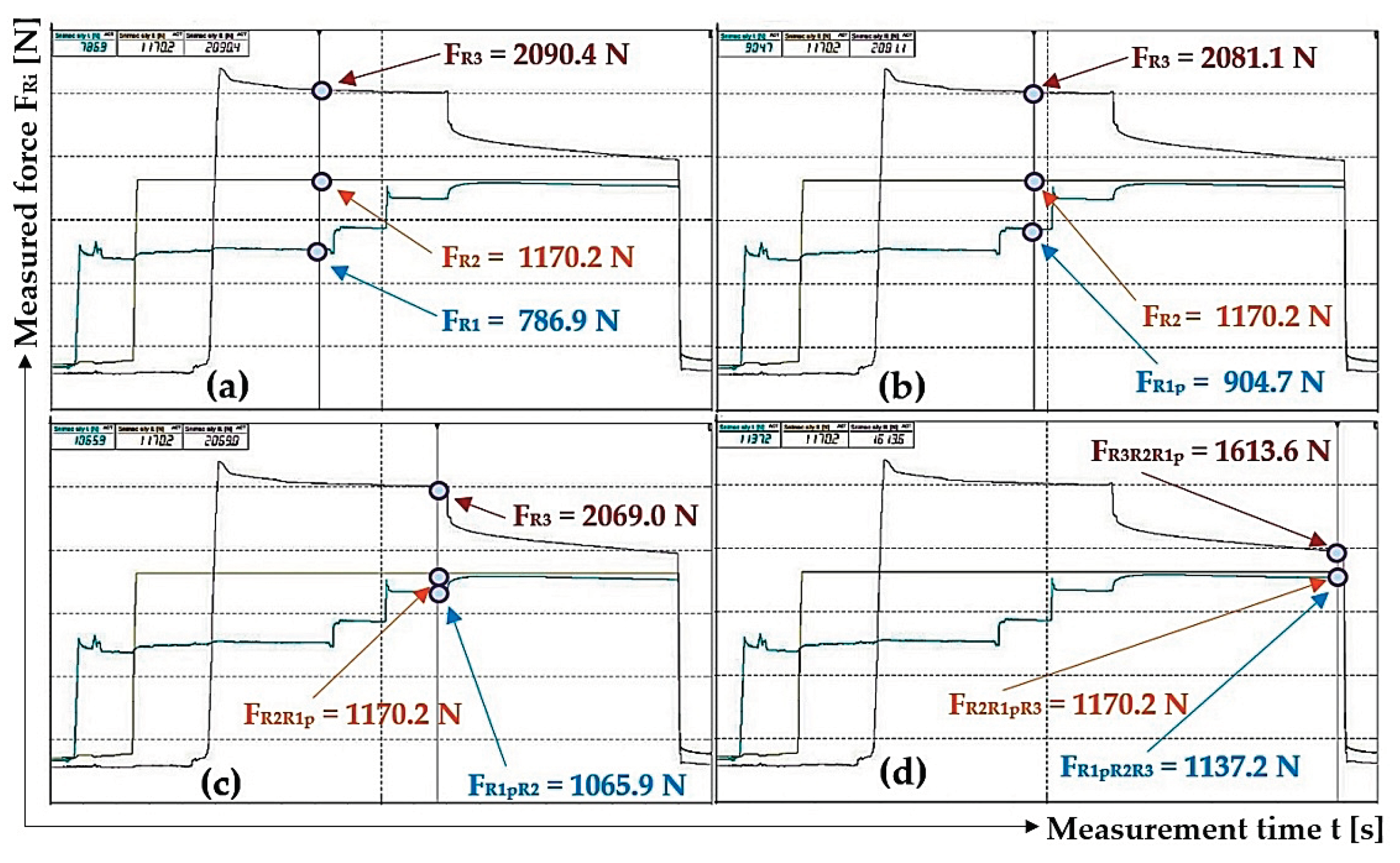

| n | FR1 | FR2 | FR3 | pp1 | pp2 | pp3 = pp |
| [N] | [106·Pa] | |||||
| 1 | 786.9 1 | 1170.2 1 | 2090.4 1 | 1.61 2 | 2.39 2 | 4.27 2 |
| 2 | 1158.7 | 531.9 | 2127.8 | 2.36 3 | 1.09 3 | 4.34 3 |
| 3 | 696.1 | 1170.2 | 2203.5 | 1.42 | 2.39 | 4.50 |
| n | FR1p | FR1pR2 | FR2R1p | FR1pR2R3 | FR2R1pR3 | FR3R2R1p | pp3p2p1p = ppr |
| [N] | [106·Pa] | ||||||
| 1 | 904.7 2 | 1065.9 3 | 1170.2 3 | 1137.2 4 | 1170.2 4 | 1613.6 4 | 3.29 |
| 2 | 1158.7 | 1158.7 | 806.1 | 1158.7 | 1009.4 | 1404.1 | 2.86 |
| 3 | 878.9 | 1170.2 | 2175.5 | 1052.5 | 1170.2 | 1623.7 | 3.31 |
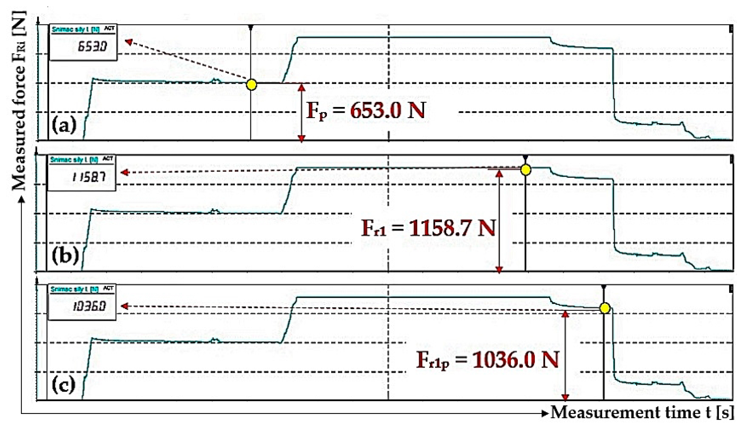
| n | Fp | FR1 | pp | pp1 | FR1p | pp1p |
| [N] | [MPa] | [N] | [MPa] | |||
| 1 | 653.0 1 | 1158.7 2 | 1.33 | 2.36 | 1036.0 3 | 2.11 |
| 2 | 285.9 | 618.5 | 0.58 | 1.26 | 593.7 | 1.21 |
| 3 | 406.5 | 938.2 | 0.83 | 1.91 | 912.4 | 1.86 |
| n | Fp1 | Fp2 | Fp3 | FR1 | FR2 | FR3 | pp | pp1 | pp2 | pp3 |
| [N] | [MPa] | |||||||||
| 1 | 285.9 1 | 318.6 1 | 297.2 1 | 642.3 2 | 1170.2 2 | 1921.5 2 | 0.58 | 1.31 | 2.39 | 3.92 |
| 2 | 606.3 | 615.6 | 618.0 | 1034.5 | 1170.2 | 1677.8 | 2.24 | 1.26 | 2.39 | 3.42 |
| 3 | 534.5 | 556.5 | 503.4 | 1104.0 | 1170.2 | 1816.4 | 1.09 | 2.25 | 2.39 | 3.71 |
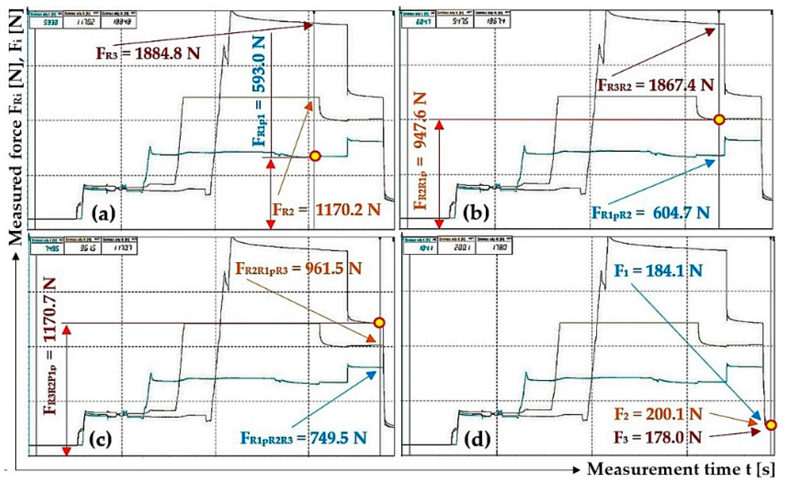
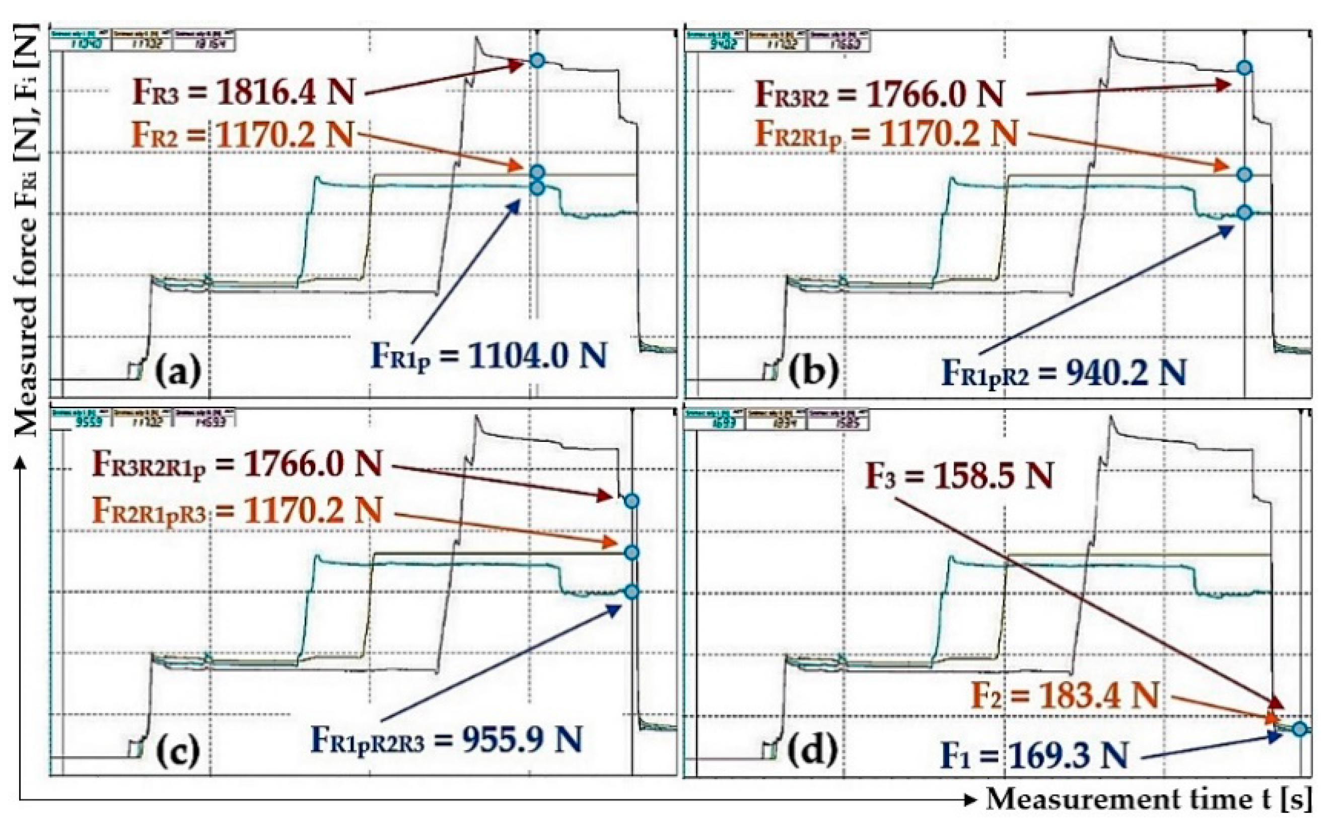
| n | FR1p1 | FR2R1p1 | FR1p1R2 | FR3R2 | FR3R2R1p | FR1pR2R3 | FR2R1pR3 | F1 | F2 | F3 |
| [N] | ||||||||||
| 1 | 593.0 1 | 947.6 2 | 604.7 2 | 1867.4 2 | 1170.7 3 | 749.5 3 | 961.5 3 | 184.1 4 | 200.1 4 | 178.0 4 |
| 2 | 1034.5 | 955.6 | 1170.2 | 1656.7 | 1005.4 | 1170.2 | 1358.9 | 534.5 | 556.5 | 503.4 |
| 3 | 1104.0 5 | 1170.2 6 | 940.2 6 | 1766.0 6 | 1766.0 7 | 955.9 7 | 1170.2 7 | 169.3 8 | 183.4 8 | 158.5 8 |
Disclaimer/Publisher’s Note: The statements, opinions and data contained in all publications are solely those of the individual author(s) and contributor(s) and not of MDPI and/or the editor(s). MDPI and/or the editor(s) disclaim responsibility for any injury to people or property resulting from any ideas, methods, instructions or products referred to in the content. |
© 2024 by the authors. Licensee MDPI, Basel, Switzerland. This article is an open access article distributed under the terms and conditions of the Creative Commons Attribution (CC BY) license (http://creativecommons.org/licenses/by/4.0/).


