1. Introduction
Revolutionizing LNG Plant Construction: A Comprehensive Comparative Analysis and Evaluation of Modular Design Development Versus Stick-Built Approach for Enhanced Efficiency and Cost-Effectiveness," focuses on exploring innovative methods to improve the construction process of LNG (Liquefied Natural Gas) plants..Traditional stick-built construction involves building each component on-site, while modular design development involves constructing pre-fabricated modules off-site and assembling them at the plant location. This study aims to analyze and evaluate the benefits and challenges of both approaches to determine which method offers the best combination of efficiency and cost-effectiveness in LNG plant construction.By comparing these two construction methods, the research aims to provide insights into how the industry can optimize the construction process to meet the growing demand for LNG facilities more effectively. The ultimate goal is to improve project timelines, reduce costs, and enhance overall project outcomes in the LNG sector.
This study makes a comparison of a modular design and a gravity base structure (GBS) concept to a conventional stick-built plant, specifically:
Land-based large individual modules
LNG process facilities mounted on concrete or steel gravity base structures (GBS) which could be located inshore, near shore, or offshore.
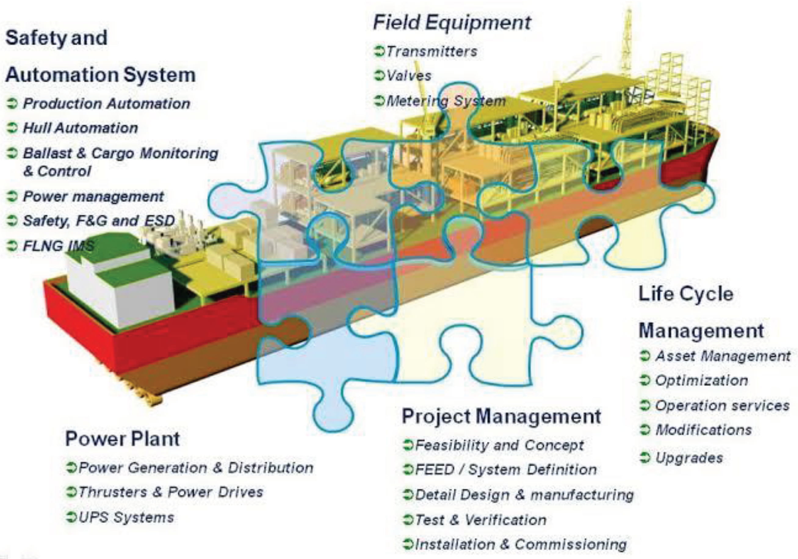
The construction constraints on the LNG plant support a philosophy of using modular construction by combining the advantages of off-site fabrication, pre-commissioning, a flexible transportation and site construction program. This philosophy is based on an analysis of the following conditions and constraints:
-

Unfavorable weather conditions at the plant site limits efficient outdoor work for lengthy periods and significantly reduce manpower productivity.
-

There is a shortage of skilled labor at the plant site. Skilled labor is costly to recruit and retain at the site for extended periods of time.
-

There are insufficient construction equipment and infrastructure facilities near the site. It would be a major effort and expense to assemble these resources.
-

There are insufficient transportation and communication services at the plant site.
-

Totally independent service providers would be required to supply these services.
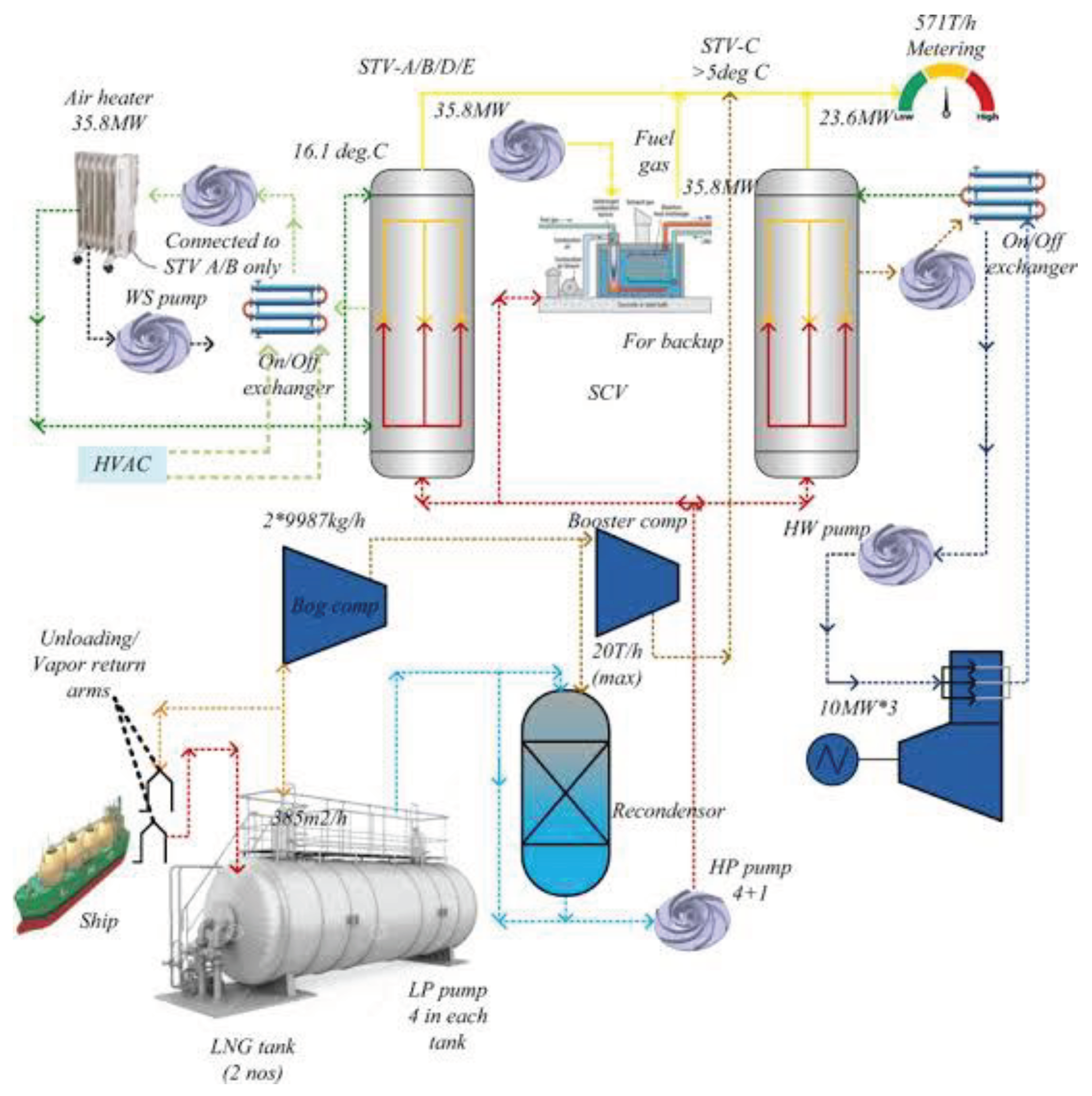
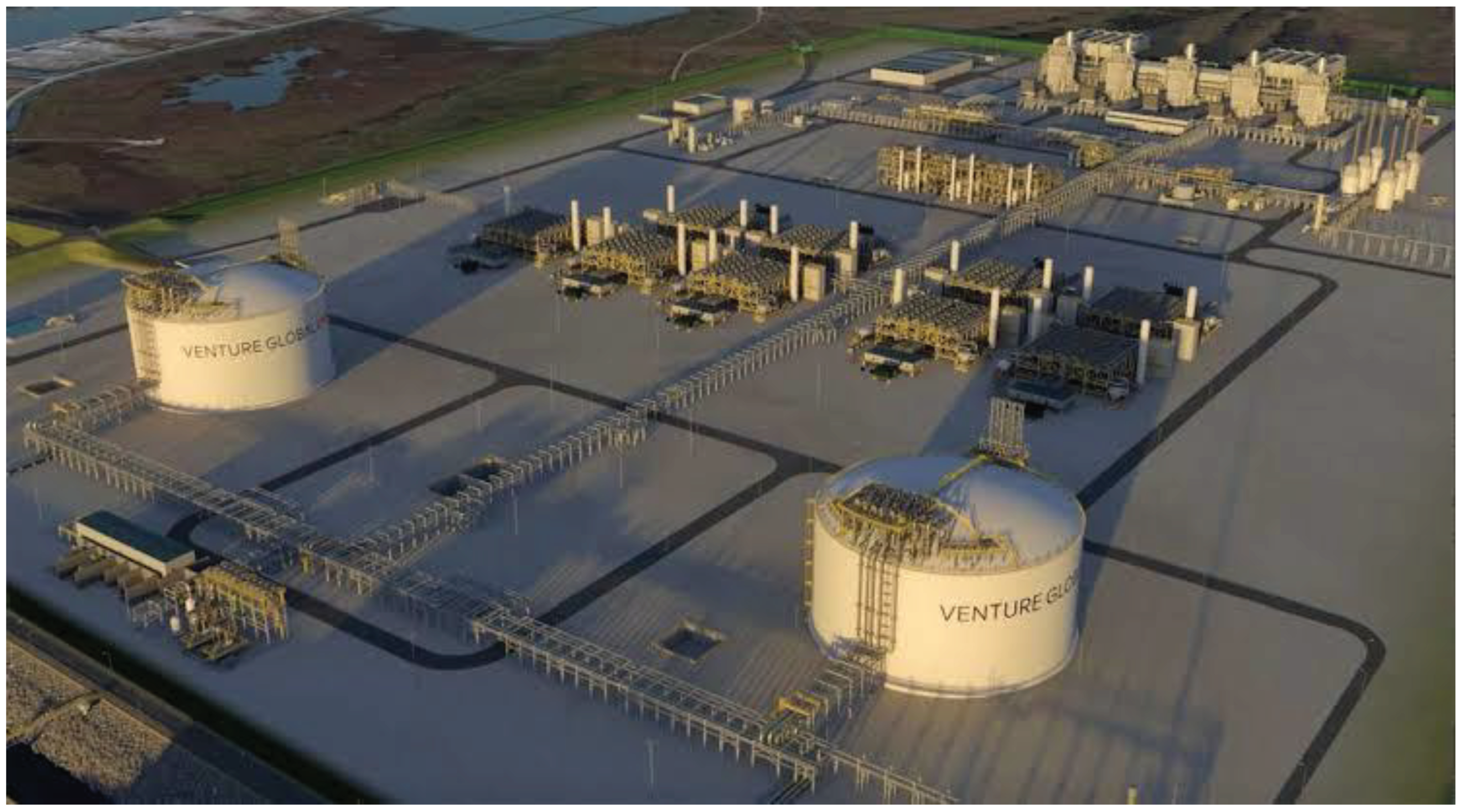
The design of the LNG facility is based on two train plant with capacity of approximately 3-4Mtpa each, based on APCI’s C3-MR liquefaction technology. There is no LPG extraction. Major utilities include power generation utilizing GTGs, steam for process heat medium, and seawater for cooling medium. Off-sites include two LNG storage tanks, condensate storage, and C2/C3 storage, WWT, flare and blow down and other miscellaneous units.
Figure 1.
Modular construction LNG Liquefaction Complex.
Figure 1.
Modular construction LNG Liquefaction Complex.
The deliverables of the research on "Revolutionizing LNG Plant Construction: A Comprehensive Comparative Analysis and Evaluation of Modular Design Development versus Stick-Built Approach for Enhanced Efficiency and Cost-effectiveness" include:
Research paper or report: A comprehensive document detailing the findings, methodologies, and recommendations of the study. This serves as a valuable resource for industry professionals, researchers, and stakeholders in the LNG sector.
Connecting these deliverables with the United Nations Sustainable Development Goals (SDGs), the following associations can be made:
-

SDG 9: Industry, Innovation, and Infrastructure: The research focuses on innovative approaches to LNG plant construction, specifically examining the benefits and challenges of modular design versus the stick-built approach. By promoting more efficient and cost-effective construction methods, it contributes to SDG 9 objectives.
-

SDG 11: Sustainable Cities and Communities: The research investigates how modular construction can reduce infrastructure requirements at a job site, minimize social infrastructure demands, and alleviate pressure on local communities. This aligns with the goals of SDG 11, aiming to create sustainable and inclusive cities and communities.
-

SDG 12: Responsible Consumption and Production: The research explores the potential for cost optimization, reduced manpower demands, and enhanced competition in module fabrication. By promoting responsible consumption and production patterns, it supports the objectives of SDG 12.
-

SDG 13: Climate Action: Modular construction can reduce construction-related emissions and environmental impacts by minimizing on-site activities and optimizing project execution. This aligns with the goals of SDG 13, which focuses on mitigating climate change and its impacts.
Overall, the deliverables of this research have the potential to contribute to several SDGs, including SDG 9 (Industry, Innovation, and Infrastructure), SDG 11 (Sustainable Cities and Communities), SDG 12
The study on "Revolutionizing LNG Plant Construction: A Comprehensive Comparative Analysis and Evaluation of Modular Design Development versus Stick-Built Approach for Enhanced Efficiency and Cost-effectiveness" holds several significant implications:
Cost Efficiency: The research provides insights into cost-effective approaches for LNG plant construction by comparing modular design with the traditional stick-built approach. This can lead to significant cost savings, improved financial performance, and enhanced competitiveness for companies in the LNG industry.
Enhanced Efficiency: By evaluating the benefits and challenges of modular construction, the study aims to identify opportunities for improving construction efficiency. This can result in shorter project schedules, reduced construction man hours, and optimized resource utilization, ultimately enhancing overall project efficiency.
Environmental Impact: The research explores the potential environmental benefits of modular construction, such as reduced on-site activities and minimized disruptions to natural habitats. By promoting more sustainable construction practices, the study contributes to minimizing the environmental footprint of LNG plant
2. Module Development
The study basis specified modules with total weight not to exceed 5000 metric tons. The module layout, spacing, and size of equipment is based on the typical plant layout criteria.
The selection of module sizes was determined by the projected weight of the modules and the structural steel base underneath a group of process equipment and associated systems.
Module weights were determined from equipment weight plus the weight of structural base and bulk materials. For the process area 22 modules were required and ranged from 500tons (e.g. C3 suction drum) to 4500tons (e.g. end flash compressor).
A total of 28 barge loads of modules were required based on barges with deck size of 400ftx100ft.
3. Gravity Base Structure Development
All process facilities be mounted on the GBS and only administration and service buildings, including the control room, were located on shore.
Definition of the GBS design criteria needed was:
GBS required height, top deck elevation etc., is determined from this information. The various GBS alternatives studied included:
Offshore location near LNG tankers loading
Near shore based on water depth
On shore location Steel GBS design
Concrete GBS design
Single GBS for typical LNG plant area
Multiple piece GBS
A matrix was then prepared to compare the results of the technical and cost parameters and for selecting a design basis for this study.
Figure 2.
Gravity Base Structure development.
Figure 2.
Gravity Base Structure development.
For the LNG trains, the GBS dimension of approx. 245 meters by 120 meters was determined by using a process area 225 meters by 100 meters plus a 10-meter perimeter around the process area. Several potential constraints exist within the design, fabrication, and installation of the GBS that were considered during the evaluation.
These constraints determine the optimum GBS configuration for a given site.
The constraints include:
-

Size of equipment plan layout and the need of preserving their functional integrity
-

Water depth requirements for adequate draft during installation
-

Water depth requirements for LNG tanker operation
-

Wave height at protected or unprotected area
-

Cost of dredging and GBS
-

Durability of the GBS during the useful life of the operation
-

Fabrication yard limits on GBS size
-

Towing requirements and limitations
-

Schedule of delivery
The water depth depends on the tankers operating conditions and draft requirements during installation of the GBS. Typically, 15m water depth is needed for taker operation and 10m for GBS installation.
Amongst the multiple layouts developed for the GBS, a one-piece steel GBS located near shore was selected, based on lowest cost, shorter delivery and better adaptability to repair.
However, due to its large size the GBS was split into smaller GBSs limited by available dock size.
The largest GBS’s were the LNG trains and the combination substation/common facilities GBS section measuring approximately 155 meters by 255 meters.
4. Comparison Of Facility Options
A comparison of the safety, technical, schedule, and cost differences between the Stick Built base case, Module case, and the Gravity Base Structure case are presented below.
4.1. Stick Built Concept
Pros
-

Safety consistent with industry practices.
-

Plant layout consistent with typical LNG facility.
-

Politically attractive with more local content.
-

Site preparation requirement normal for LNG facility. Marine work normal for LNG jetty and docks.
Cons
-

Highest requirement for construction manpower on a total and peak man power basis.
-

Highest requirement for skilled labor and training of available manpower.
-

Highest requirement for construction camps, major construction equipment, and temporary construction facilities.
-

Highest impact, if severe weather conditions reduce normal construction season.
-

Moderate opportunity for competitive bid conditions. Higher capital cost than the module case.
4.2. Module Case
Pros
-

Lower requirement for Site construction manpower on a total and peak Manpower basis.
-

Lower requirement for skilled labor and training of available manpower.
-

Lower requirement for construction camps, major construction equipment and temporary construction facilities.
-

Lower impact, if severe weather conditions reduce normal construction season.
-

Marine work normal for LNG jetty and docks.
-

Good opportunity for module assembly to be competitively bid, based on the large number of module fabrication yards available. Lower capital cost than the stick-built case.
Cons
-

Safety consistent with industry practices with design consideration for filling steel base structure to prevent accumulation of gases.
-

Plant layout is consistent with typical LNG facility but consideration should be given during layout development to improve the cost benefits of modularization without sacrificing safety and plant integrity.
-

Highest site preparation requirements due to excavation for module bases at grade level, back-fill requirements and wider roads to accommodate module transport vehicles.
-

Politically less attractive due to less local content, if module fabrication not performed in-country.
4.3. Gravity Base Structure
Pros
-

Lowest requirement for construction manpower on a total and peak manpower basis.
-

Lowest requirement for skilled labor and training of available manpower.
-

Lowest requirement for construction camps, major construction equipment, and temporary construction facilities.
-

Lowest impact if severe weather conditions reduce normal construction season.
-

Lowest site preparation since most of the hydrocarbon facilities are offshore.
-

Moderate opportunity for competitive bid conditions. Module fabrication is a highly competitive bid situation, but GBS is low competitive bid situation.
Cons
-

Safety can be consistent with industry practice by providing a design to prevent accumulation of gases in the module and the large GBS; by providing designs to account for potential movement between GBS; and by providing appropriate methods of personnel movement during emergencies.
-

Highest capital cost due to the number, size, and tonnage requirements for GBS.
-

Highest requirement for marine work due to the majority of interconnecting piping installed offshore near the GBS.
-

Shipyards facilities may not be sized to accommodate a large GBS, as required for this plant, and demand at the time of the study indicated need for advanced commitment of shipyard space.
-

LNG tank installation on GBS will require 54-month duration. The alternative is for the LNG tank and flare system on-shore (see Construction Schedules).
-

Politically least attractive due to least local content, if module and GBS fabrication not performed in-country.
5. Construction Schedules
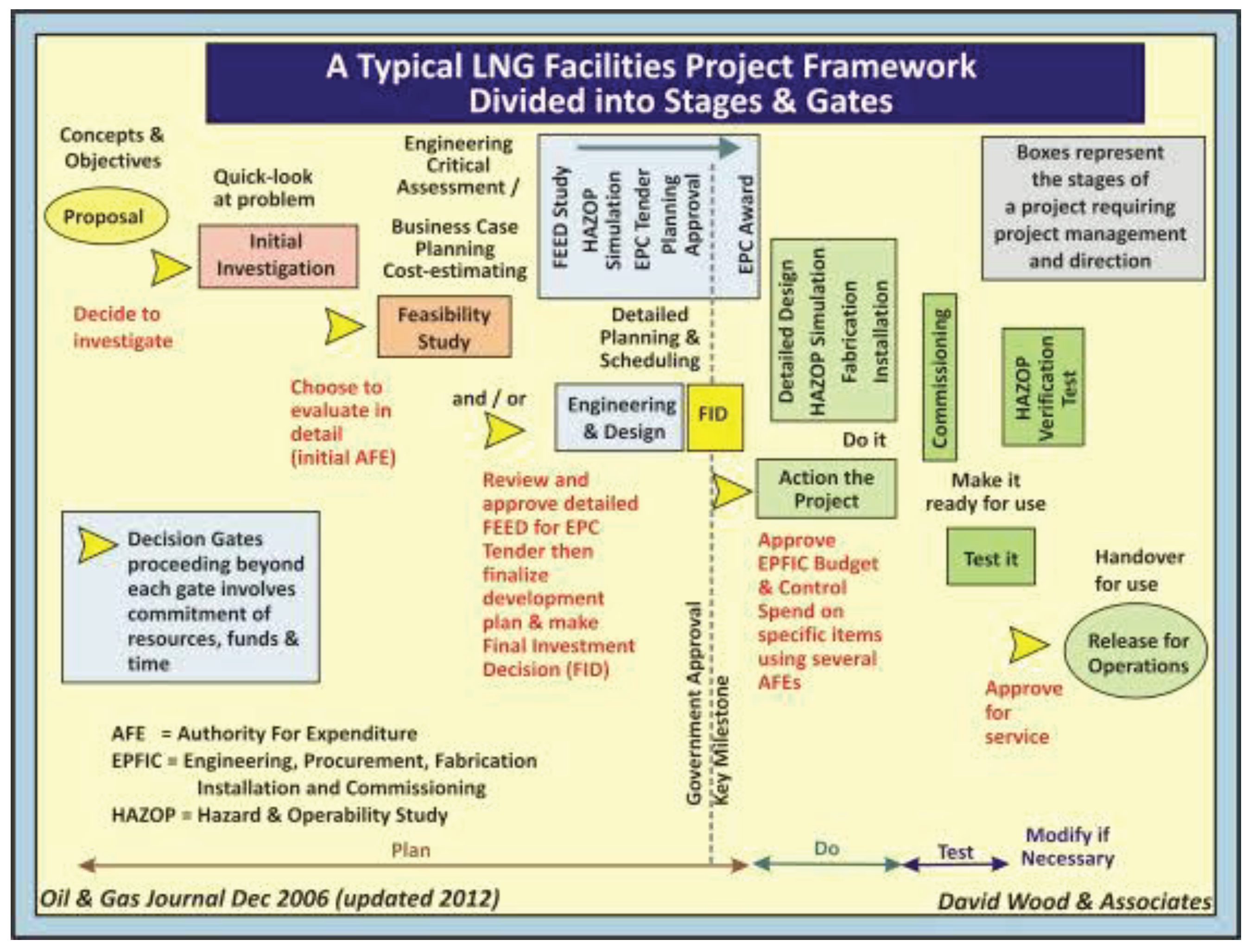
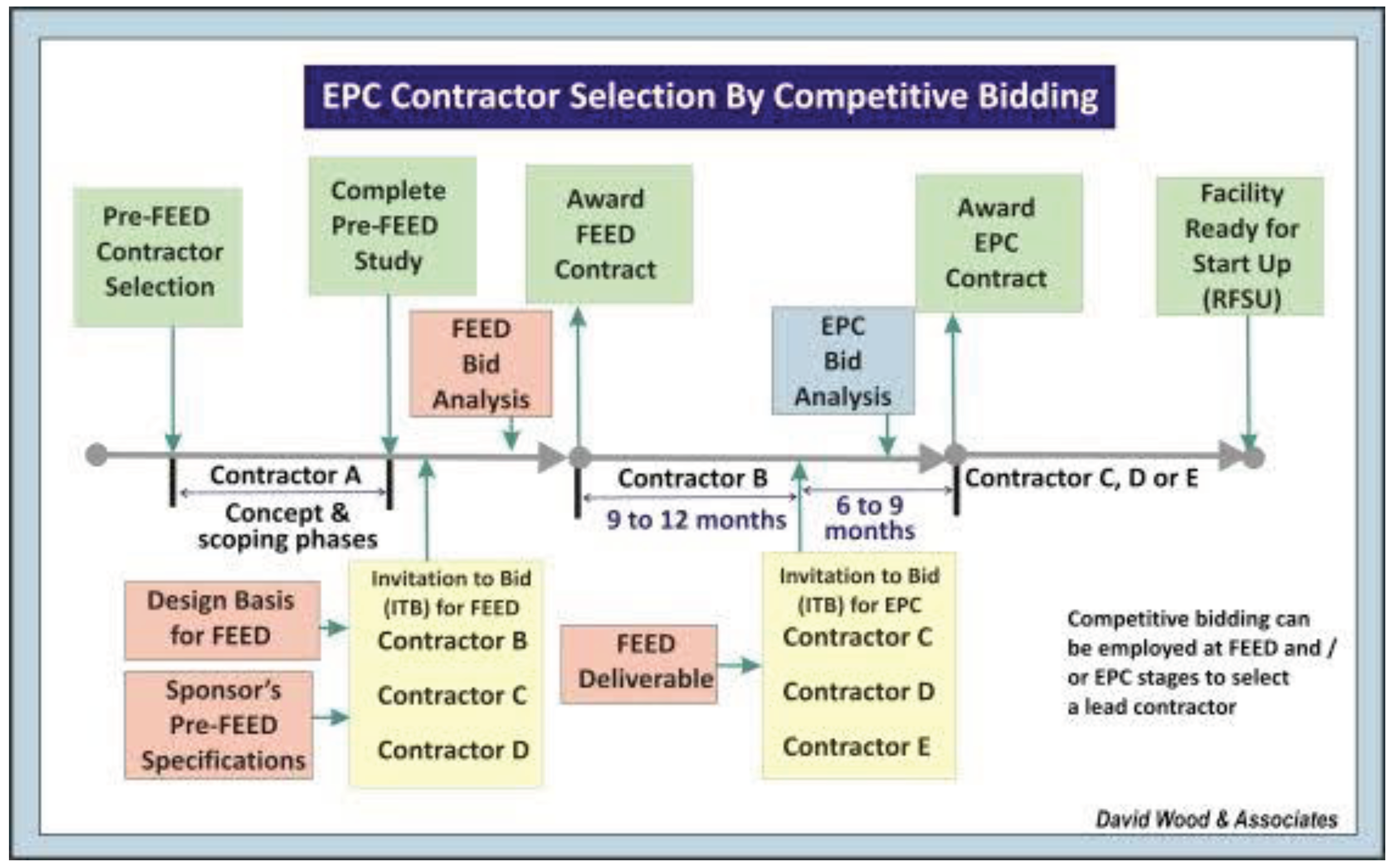
The EPC schedule was set by long lead equipment deliveries, reduced work in the winter season, high manpower levels in the summer season, 60 hours work week, and the duration for installation and commissioning. Recognizing that the overall Engineering, Procurement and Construction (EPC) will involve at least three winter seasons and that there is a six (6) month interval between the start-up dates of LNG train #1 and #2, the project schedule required an evaluation of the timing of certain activities. The evaluation resulted in the following basis:
-

For the shortest EPC schedule, engineering and procurement activities will begin prior to the EPC contract award for the preparation of bid packages for long lead equipment. Examples of these long lead items include the LNG tanks, the gas turbine/compressor, and cryogenic equipment.
-

Installation of the two LNG tank requires a parallel construction effort thus requiring twice the manpower, the construction equipment, staff, concrete batch plant, shops and camp accommodations. Summer double shift operations are necessary for each tank, requiring additional camp accommodations.
-

For the Gas turbine driven compressors, the schedule assumes the following: a). delivery in 27 months after award; b) installation in 9 months; c) testing in 4 months; and d) commissioning in 3 months. The compressors are considered the critical path for the LNG trains.
-

The construction work schedule will be 60 hours per week. For a remote site the normal construction practice is for longer work hours to attract skilled labor.
-

With the start of construction in January of Year 2, a construction camp and related construction resources become a critical early contract commitment. This requirement is based on lead time for engineering, fabrication, delivery, and installation of construction camps and related construction resources. Thus, the schedule requires that the bid packages and award of these components be completed soon after the award of the EPC contract.
-

Site mobilization will start in September of Year 1 to support the installation of construction camps and mobilization of equipment and supplies.
-

Site preparation, underground, and foundation work can effectively be performed in the winter months when compared to other construction activities, since maintaining a heated environment in the manned equipment is a not difficult or costly. In fact, excavation and soil movement activities in the winter conditions are preferred. Thus, January of Year 2 was selected for the start of site preparation work and April of Year 2 was selected for the start of underground/foundation work. During Year 2 all the site, underground, and foundation work is completed for all facilities.
-

Similar to the site preparation work, the offshore construction work related to the jetty causeway and the material loading facilities was selected to start in January of Year 2.
-

With a six (6) month interval between LNG trains and the normal duration of structural and piping activities, there is an advantage to have most of this work performed in the summer months. Other construction activities like electrical, instrumentation, pre-commissioning and commissioning will have a duration of nominally twelve (12) months, based on the interval between LNG trains.
The following paragraphs highlight key activities for each of these EPC schedules:
5.1. Stick Built Option
Site mobilization starts in September of Year 1 to install temporary construction camps. Site preparation, jetty causeway construction, and loading dock construction begins in January of Year 2 Foundation and underground work begin in April of Year 2 including LNG tanks and building foundations. Three months later structural steel erection begins followed by pipe installation, placement of equipment, electrical and instrumentation. Insulation, painting, hydro-testing, pre-commissioning, and commissioning activities will be accomplished as the construction work is completed on an area or system basis. The construction activities are sequenced to take advantage of the crews moving from train #1 to train#2.
The winter manpower is reduced and directed to specific areas of inside work or where temporary enclosures can be erected. Manpower is increased for the second summer season for concentration on pipe rack work, placement of equipment, pipe spool installation, electrical/instrumentation painting and testing.
5.2. Module Option
For the module case, the construction activities for stick-built work at job site follows the program as stated above. The modules will be constructed in a fabrication yard on a structural skid to support the equipment and provide a platform for transportation.
A module base fabrication contract is awarded in December of Year 1. Six months are required for module base fabrication and delivery coincides with the award of module assembly contract. The module assembly contract award is in June of Year 2. The module fabrication time frame is 19 months. The pipe rack modules will start to be shipped in April of Year 3 and the last module will ship in January of Year 4. The gas turbine driven compressor modules will be the last modules shipped. Load-out, ocean transportation from a fabrication yard port, and module placement on foundations requires approximately three weeks for each module. Module connections and final testing is ongoing through mechanical completion after the first shipments of modules are placed on foundations.
Figure 3.
Project Schedule Stick Built Construction.
Figure 3.
Project Schedule Stick Built Construction.
5.3. GBS Option
For the GBS case the construction activities for stick-built work at job site and module assembly follows the program as stated above. The modules will be constructed in a fabrication yard on a structural skid to support the equipment and provide a platform for transportation.
The GBS units will be built in multiple fabrication yards. The GBS contract is bid and awarded within eight months of EPC award. GBS design will take 8 months and fabrication will take 17 months. Placement of modules on GBS, final hook-up and connections, and transport will span 11 months. Since the LNG tank fabrication depends on GBS completion, the LNG tanks on a GBS is shown to be completed in the 54th month.
Figure 4.
Project Schedule Module Construction.
Figure 4.
Project Schedule Module Construction.
Figure 5.
Project Schedule Gravity Base Structure.
Figure 5.
Project Schedule Gravity Base Structure.
5.4. LNG Tanks
At the time of the study, supplier information indicated that the LNG tank may require 36-38 months to complete after order placement, when considering a normal environment. A double shift plan results in completion of the tanks 8 months earlier than on a single shift basis which is a total 38 months after order placement.
6. Constructions Man Loading
The summary of the total construction man-hours is shown below. These man-hours have been adjusted by using productivity factors of 1.25 for fabrication yard and 2.25 for job site (e.g. U.S. Gulf Coast productivity of 1.00 base line).
Table 1.
Construction Total Man-hours (millions).
Table 1.
Construction Total Man-hours (millions).
| Option |
Site(job) |
Yard(fabrication) |
Overall Total |
| modular |
19.8 |
9.7 |
29.3 |
| Built(stick) |
34.5 |
----- |
34.5 |
| GBS |
15.7 |
29.8 |
45.6 |
6.1. Stick Built Construction Man-Loading
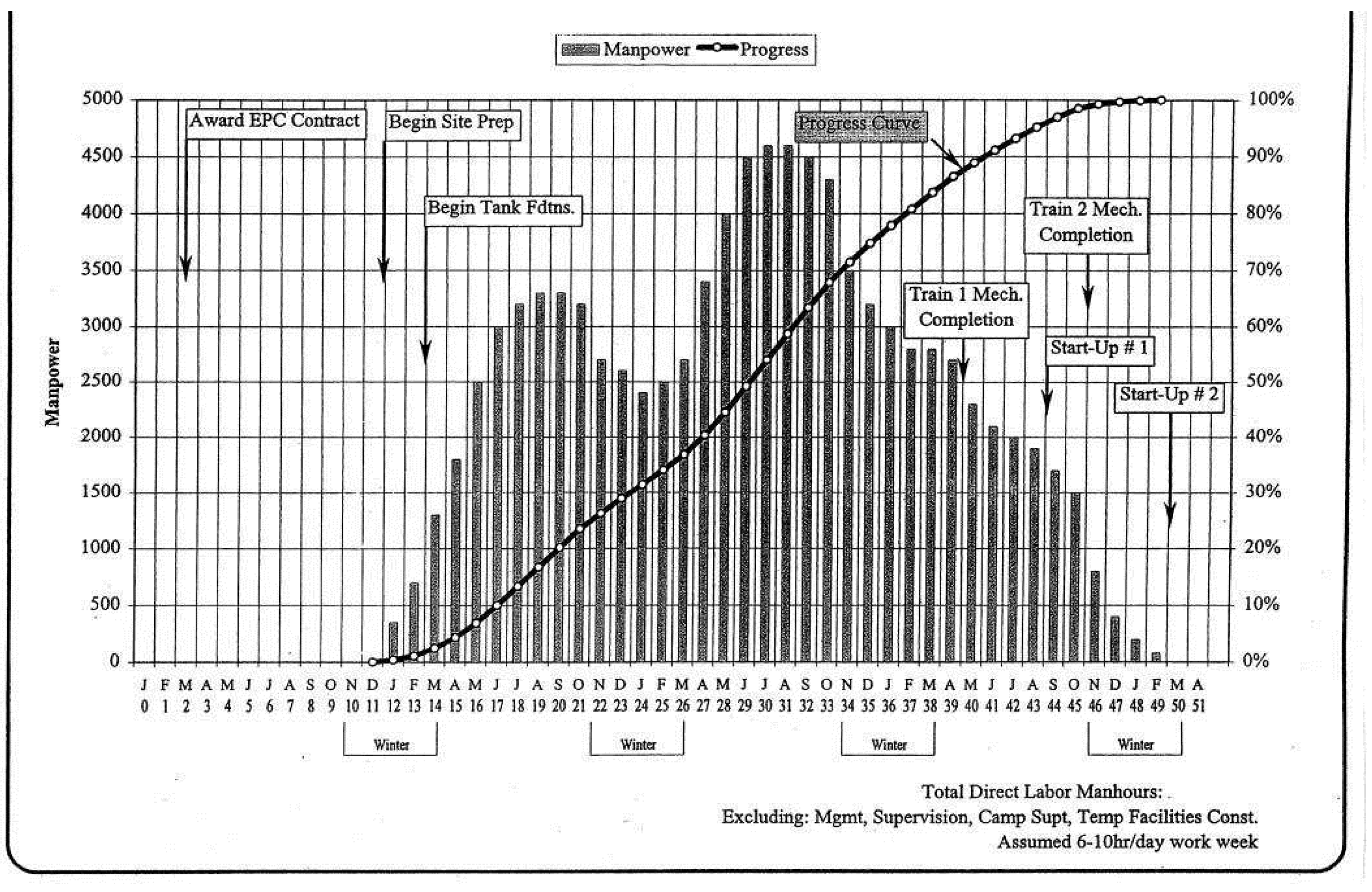
The direct labor manpower requirements for the stick-built option were prepared to determine the number of skilled craftsmen required for construction of the LNG Plant. Direct labor man-loading is shown in Figure below. Manpower not included are temporary facilities construction personnel, management, supervisory personnel, and camp operation personnel. The craft manpower requirement peaks at approximately 3,300 craft during the first summer season and 4,600 craft during the second summer season.
The direct labor man-loading was develop based on the following:
-

The manpower will increase dramatically during the summer months to take advantage of the weather conditions conducive to better productivity. (April through October).
-

Selected construction work will continue on a year around basis, especially the construction of the LNG tanks and jetty.
-

There are construction challenges associated in the stick build LNG Plant. Further evaluations are required of the following challenges:
-

Availability of large labor forces in excess of 5,500 skilled craftsmen for summer periods
-

Congestion of work areas by concentrated work activities
-

Mobilization and demobilization of reduced labor forces during summer phases
-

Logistics of maintaining the construction camps on a year-round basis
-

Level of skill and training requirements for craft/supervisors Detailed planning and scheduling of work activities
-

Impacts, if any, of other projects in the development scheme
-

Labor inefficiency due to labor turnover every 6-month period. (i.e. it’s likely that the labor will not return on the following summer period)
Figure 6.
Stick Built construction direct manpower requirements & progress curve.
Figure 6.
Stick Built construction direct manpower requirements & progress curve.
The EPC schedules and man-loading plan indicate that it is feasible to stick build the plant in the 39/45-month time frame, provided that there is manpower availability and a successful training program to support the level of skilled manpower required.
But there is a concern regarding productivity and weather conditions that could impact project cost and schedule.
The stick-built option has 33 million estimated man-hours (direct and indirect) that equates to an approximate average manpower of 3,300. This manpower plan is based on a 38-month construction period and a 60-hour work week. The peak manpower, including camp and other temporary construction facilities during the manpower increase in the summer months, will be approximately 6,000 men.
6.2. Module Construction Man-Loading
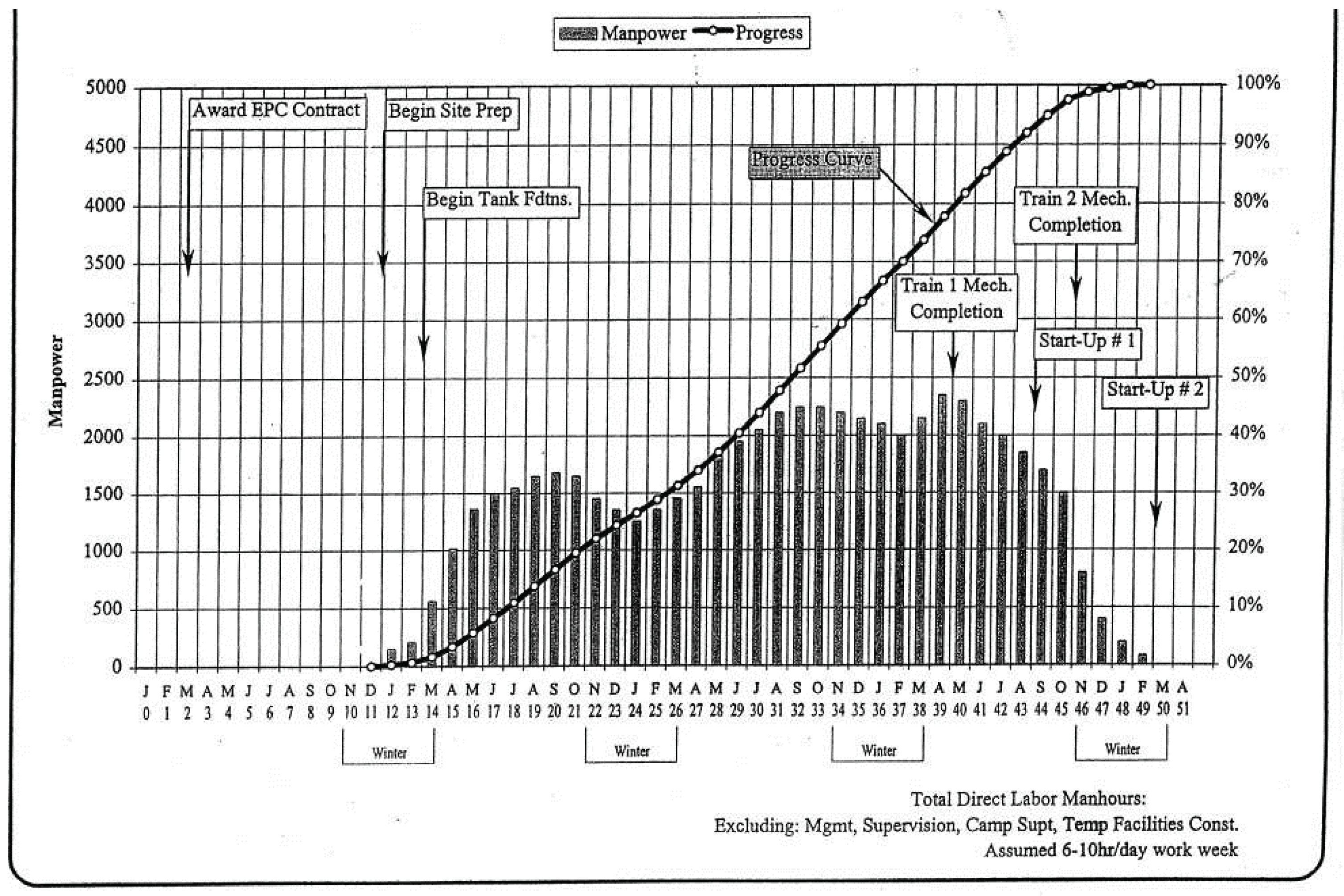
The onsite direct labor manpower requirements for the module option were prepared to determine the number of skilled craftsmen required for construction of the LNG plant. Direct labor man-loading for site is shown in Figure below. Manpower not included are temporary facilities construction personnel, management, supervisory personnel, and camp operation personnel. The craft manpower requirement peaks at approximately 1,650 craft during the first summer season, and 2,250 craft during the second summer season.
Figure 7.
Module construction direct manpower requirements & progress curve.
Figure 7.
Module construction direct manpower requirements & progress curve.
The direct labor man loading was developed based on the following:
-

The manpower will increase dramatically during the summer months to take advantage of the weather conditions conducive to better productivity (April through October).
-

Selected construction work will continue on a year around basis, especially the construction of the LNG tanks and jetty.
The EPC schedules and man-loading plan indicates that it is feasible to build the plant using modules in similar time frame as stick built, however with much lower construction man hours at site. While there is still some concern regarding productivity and severe weather conditions that could impact project cost and schedule, these conditions will be less severe than the stick-built option.
The module option will reduce the number of man-hours required at the LNG plant site by 14 million (direct and indirect). The remaining 19-million-man hours (direct and indirect) at the LNG Plant site work, equates to an approximate average manpower of 2,000. The peak manpower, including camp and other temporary facilities during the manpower increase in the summer, will be approximately 3,000 men.
6.3. GBS Option Man-Loading
The GBS option will reduce the number of workers required at the LNG Plant site by a total of 18 million man-hours (direct and indirect). The remaining 15 million man-hours (direct and indirect) at the LNG plant site for other stick-built work equates to an approximate average manpower of 1,400. This is based on a 41-month construction period and 60-hour work week. The peak manpower, including camp and other temporary facilities during the manpower increase in the summer months, will be approximately 2,400 men.
6.4. GBS Construction
The onsite direct labor manpower requirements for the GBS option were prepared to determine the number of skilled craftsmen required for construction of the LNG plant. The craft manpower requirement peaks at approximately 1,600 craft during the first summer season, and 1,900 craft during the second summer season.
The EPC schedules and man-loading plan indicate that it is not feasible to build the plant using the GBS concept in the time frame similar to the other two options. This is due the length of time to design, fabricate, and ship the GBS platform prior to installation of the modules onto the structures with delivery, placement, testing, and commissioning at job site. The LNG tank will require 54 months to complete on a GBS platform. The LNG train #l and #2 will require respectively 42 and 48 months to complete on a GBS platform.
The LNG tanks could be completed earlier on shore rather than on a GBS, but that design will require considerably longer loading and vapor return lines.
7. Logistics (Module And Gbs)
The requirements for module and GBS transportation and placement at the site are described below.
7.1. Module Loading
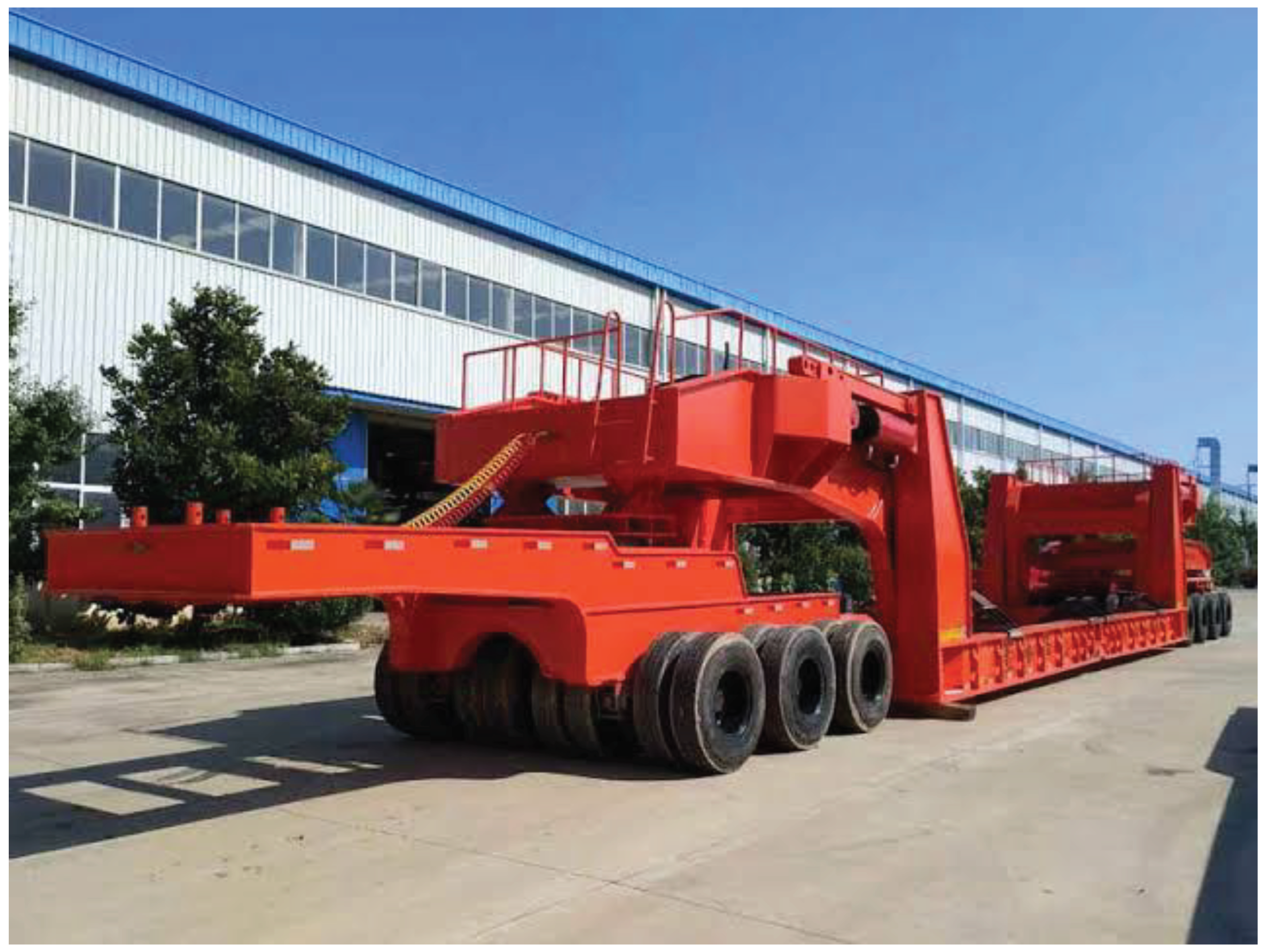
The modules will be built at the various assembly sites elevated four feet to permit a lowered platform trailer to be driven under the module. Once the trailer is under the center of gravity of the modules, the hydraulic rams in the axles are energized and the module is lifted clear of the ground. Figure below shows the end and side views of module transportation approach.
Figure 8.
Module Loading (towed hydraulic platform trailers and self-propelled hydraulic platform trailers).
Figure 8.
Module Loading (towed hydraulic platform trailers and self-propelled hydraulic platform trailers).
There are two types of trailers available, namely towed hydraulic platform trailers or self-propelled hydraulic platform trailers. Lighter modules under 1,500 tons can be moved with towed trailers saving considerable cost. The advantage of platform trailers is that they provide support at two or three points on each of the module's transverse girders.
All modules would be loaded on the barges by driving the trailer with module on to the barge while the barge is being ballasted. Once positioned on the barge in the proper stow location the module will be lowered onto the barge deck using the trailer hydraulic suspension. Continuous transportation beams under the module will spread the module's load into the barge's transverse frames. The modules will then have tie-down clips installed between the transportation beams and barge deck. The trailers used for loading will stay in fabrication site and a second set of trailers will be used on job site.
7.2. Barge Requirements
The deck barges were chosen because of the width and length of modules (which do not fit well on roll-on/roll-off ships), the short distance from the assembly site, the ability to go direct into a shallow dock, and the capability to ballast the barge to the seabed which allows for quicker discharging.
Based on the module list, stow plans were developed for all the modules resulting in a requirement of 28 barge loads of modules to be moved from fabrication yard to Site.
The quantity is based on using barges with a deck size of 400 feet long x 100 feet wide and either straight deck barges or semi-submersibles. The estimate uses 17 barges for the first trip (sea lift) from fabrication yard and then 11 barges return to pick up the second LNG train.
7.3. Barge Unloading
Once the barges have arrived at site, shallow drafting assist tugs will take the tows from the line-haul, ocean going tugs and bring them to the materials offloading facility (MOF). The MOF is situated in about three to four meters of water permitting the local tugs operating water depth. Unloading would be done during moderate weather and sea conditions keeping ballasting to a minimum and wave surge down.
While the barge is being ballasted down to the prepared bottom (typically a gravel pad), crews will burn-off the module tie-down clips. When the barge is level with the dock, platform trailers will drive under the first module, lift it clear of the barge deck and drive off the barge. This usually takes some minor ballasting depending on the module weight. Any loose cargo would be removed with fork lifts or cranes to flatbed trailers.
Several trailers will be used to move the modules to their foundation or stage the modules to speed the turn-around of the barges. The basic route to the facilities will require substantial earthwork to allow a 40 ft roadway plus having no obstructions 55 ft. to either side of the road center-line for module clearance.
7.4. Module Setting
Typically, the module setting will be done by setting the module initially on jacks which will be located in pockets in the grade beam.
The modules will be jacked down using upside down jacks and dimensioned cribbing to eliminate safety cribbing alongside each jack. Some modules such as the overhead air coolers and taller vertical vessels will be moved by trailers alongside the LNG Train and set at long radius by crane with suitable capacity and reach.
7.5. GBS Movement
Basically, these units will be towed by multiple tugs from the GBS assembly site(s) to the module assembly site. There the GBS will be partially ballasted down and large capacity crane barges will be used to lift and place the modules on the deck of the GBS.
Platform trailers (RTV's) will be used to move the modules to their final locations. After the modules have been interconnected and tested, the G's will be towed to final site, positioned using tugs and winches connected to anchors and ballasted down.
8. Cost Estimate
The project estimate includes all costs incurred by the prime contractor that will be required to construct the LNG plant.
This includes the cost of engineering studies, detailed design and procurement, materials, module and/or gravity base structure (GBS) fabrication, transportation and logistics, field assembly and hook-up of the modules and/or GBS, contractor management, and field labor overheads.
The scope of the estimate includes all the costs for facilities in a harsh environment employing modular construction techniques. Costs for all estimates were prepared on factored concept using the cost of equipment and installation multipliers to establish a USA Gulf Coast stick-built cost and then adjusted for the site stick-built costs and modular packaging as required.
Costs cover all equipment, materials, fabrication and installation services. Modules are suitable for ocean shipment to Site as deck cargo on towed barges. Module handling and movements are via purpose-built transport vehicles. Final installation and plant completion is made at site.
The estimates are based on the equipment list and equipment weights. Price levels reflect worldwide procurement. The modules and GBS are assumed to be fabricated at fabrication yards with suitable sea front access for transportation.
The scope of the estimate excludes Owner related capital costs such as personnel, management and engineering, catalyst, taxes, duties, escalation, contingency, etc. The intent of the estimate is to reflect accurate costs for the facilities as defined within a range of +/- 30%.
Estimate Comparison
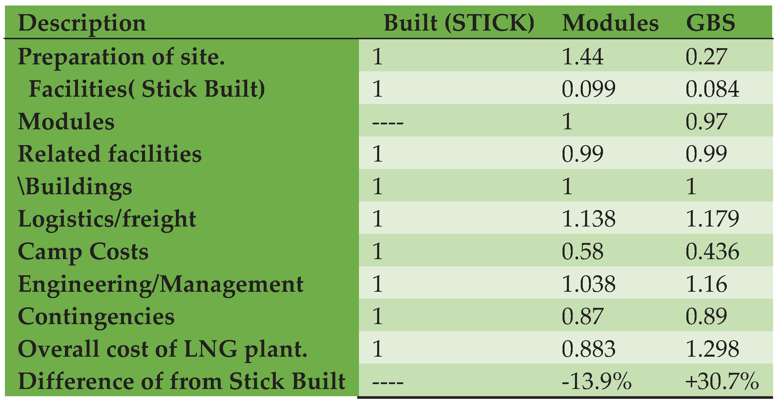
The Table below shows the comparative cost estimate for each of the study options.
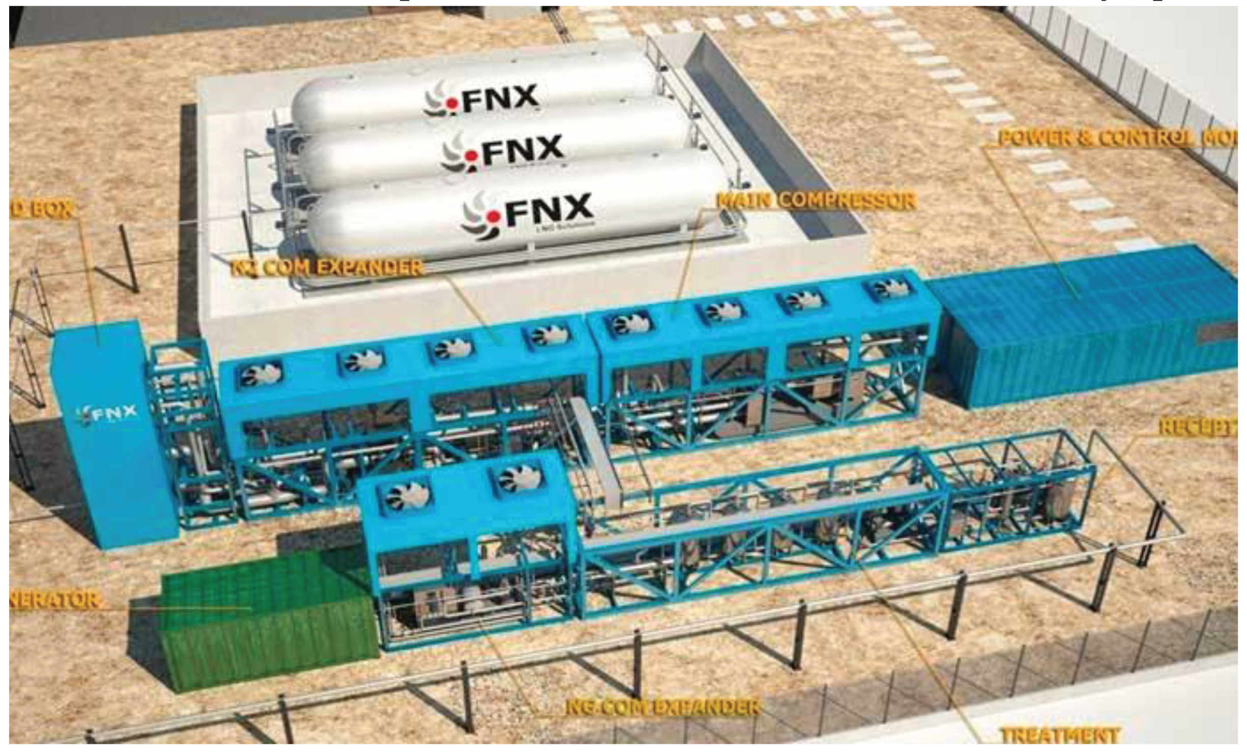
Figure 9.
modular small scale LNG plant.
Figure 9.
modular small scale LNG plant.
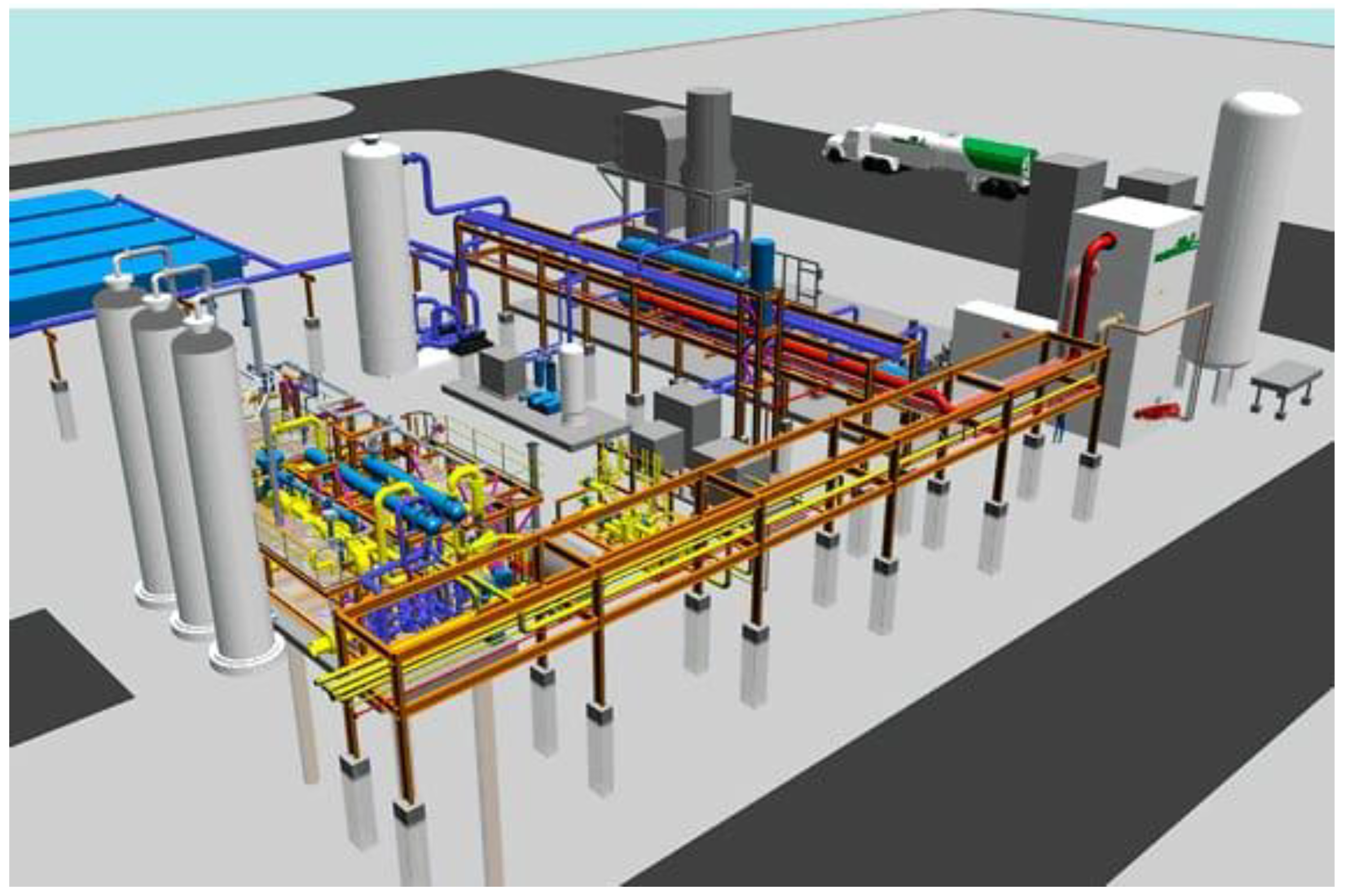
Figure 10.
small scale modular and park shaving processes .
Figure 10.
small scale modular and park shaving processes .
Figure 11.
News content hub mid-scale, modular LNG Liquefaction plant.
Figure 11.
News content hub mid-scale, modular LNG Liquefaction plant.
Table 2.
Comparative Cost Estimate .
Table 2.
Comparative Cost Estimate .
9. Conclusions
Based on the findings, the conclusions drawn from the analysis are as follows:
-

The total direct cost of implementing a modular LNG plant is approximately 10.5% lower compared to a stick-built approach.
-

The Total Installed Cost (TIC) of the modular case is estimated to be around 13.9% less than that of the stick-built case.
-

The estimated contingency for the modular case is approximately 15% lower than that for the stick-built case. This reduction reflects the decreased risk and uncertainty associated with project delivery in the modular approach.
-

It should be noted that the overall weight of a modular plant is around 20% greater than that of a stick-built plant due to the increased amount of steel required for modular construction.
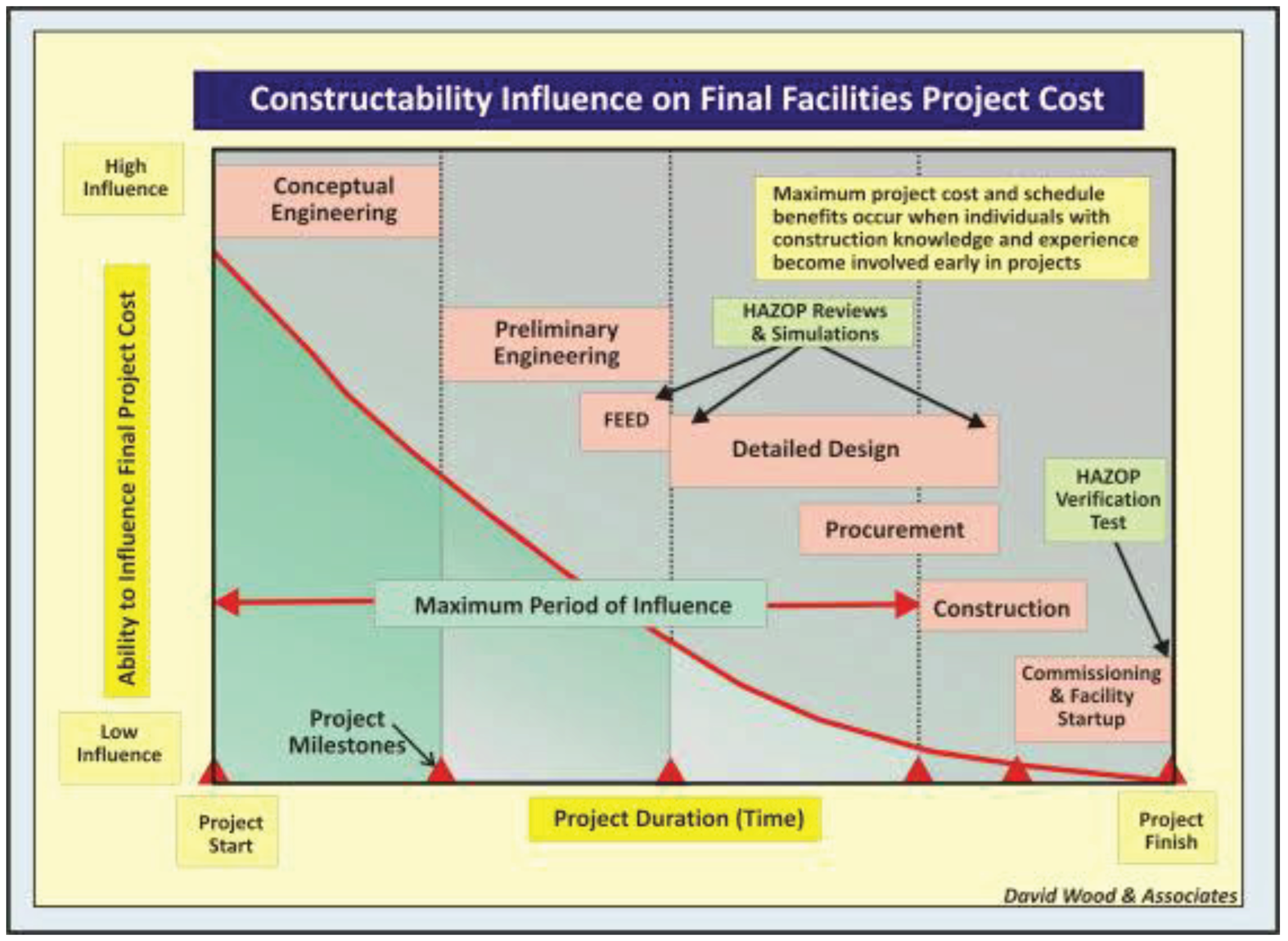
The analysis suggests that modular construction offers cost advantages in terms of direct costs, TIC, and contingency. However, it is important to consider the increased weight associated with modular plants, which can impact logistics and transportation. Ultimately, the decision to adopt a modular or stick-built approach should be based on a thorough evaluation of the specific project requirements and cost considerations
-

The modular design approach necessitates a higher level of early engineering quality and a larger management effort, resulting in a 4% increase in associated costs.
-

Although fabrication hours increase by approximately 30%, overall fabrication costs are 28% lower due to the utilization of lower-cost Labor rates in fabrication yards.
-

The modular construction approach can result in a reduction in construction man hours by up to 15% due to a significant decrease in field construction scope.
-

Construction camp costs for a modular plant are estimated to be 42% lower compared to stick-built construction.
These additional conclusions further highlight the cost implications and considerations associated with modular design and construction, such as the need for early engineering quality, the impact on fabrication hours and costs, the reduction in field construction scope, and the potential for cost savings in construction camp expenses. These factors should be thoroughly evaluated alongside other project-specific considerations when deciding on the most suitable construction approach.
Recommended Approach
After conducting a comprehensive comparison of stick-built, modular, and gravity base structure (GBS) options for an LNG plant, the recommended approach is to adopt modular construction. This recommendation is based not only on cost considerations but also on other significant factors. Firstly, modular construction allows for a safe plant design, ensuring the highest standards of safety and quality. Secondly, it offers the advantage of the lowest capital cost, providing cost-effectiveness in the construction phase. Additionally, the recommended modular approach offers a realistic and achievable schedule, ensuring timely project delivery. Furthermore, there is also potential for further reduction in capital costs by exploring optimization opportunities within the modular construction process. Taking all these factors into account, the modular approach emerges as the Most favorable option, offering a blend of:
• The modular construction approach minimizes exposure and reduces cost and schedule impacts in case of prolonged adverse weather conditions.
• It helps alleviate pressure on local social infrastructure at the job site, as the majority of construction activities are carried out off-site.
• Modular construction allows for the highest potential for cost optimization by maximizing the areas of modularization in the project
• By utilizing a broader labor market, the modular approach is not solely dependent on local labor conditions, providing flexibility in sourcing
• The modular construction approach reduces the infrastructure requirements at the job site, as a significant portion of construction activities is shifted to off-site fabrication yards.
• It also results in a reduction in job site manpower demands and related construction facilities, as a substantial portion of the work is completed in the controlled environment of the fabrication yard these advantages of the modular construction approach contribute to improved efficiency, reduced costs, and minimized disruptions at the job site. It allows for a more streamlined construction process and enhances overall project management and execution
References
- Smith, A.B. , & Jones, C.D. Innovations in Modular Design for LNG Plant Construction. Journal of Construction Engineering and Management 2015, 31, 101–115. [Google Scholar]
- Brown, E.F. Sustainable Practices in Stick-Built LNG Plant Construction. Sustainable Development Journal 2016, 19, 221–235. [Google Scholar]
- Johnson, G.H. , & White, L.M. Comparative Analysis of Modular Design and Stick-Built Approaches in LNG Plant Construction. Energy Engineering Review 2017, 7, 87–102. [Google Scholar]
- Lee, S.T. , et al. Cost-Effectiveness Evaluation of Modular Design Development in LNG Plant Construction. Energy Economics Today 2018, 42, 55–68. [Google Scholar]
- Garcia, R.D. , & Patel, K.S. Efficiency Improvement Strategies for Stick-Built LNG Plants. Construction Technology Innovations 2019, 15, 75–89. [Google Scholar]
- Wang, Y. , et al. Environmental Impact Assessment of Modular Design Development in LNG Plant Construction. Sustainable Energy & Environment Journal 2020, 28, 123–137. [Google Scholar]
- Turner, J.R. , et al. Automation and Digitalization Trends in Stick-Built LNG Plant Construction. Journal of Engineering Technology 2021, 39, 201–215. [Google Scholar]
- Harris, D.W. , & Wilson, P.L. Risk Management in Modular Design Projects for LNG Plant Construction. Journal of Risk Analysis 2022, 12, 67–81. [Google Scholar]
- Martinez, L.M. , et al. Regulatory Compliance Considerations for Stick-Built LNG Plants. Regulatory Affairs Review 2023, 25, 33–47. [Google Scholar]
- Kim, J.H. , et al. Technological Advancements in Modular Design for LNG Plant Construction. International Journal of Construction Innovation 2015, 8, 145–159. [Google Scholar]
- Anderson, R.M. , & Clark, L.T. Sustainability Factors in Stick-Built LNG Plant Projects. Journal of Sustainable Development 2016, 22, 187–201. [Google Scholar]
- Thompson, N.W. , et al. Modular Construction: A Game Changer for LNG Plant Efficiency. Energy Efficiency Journal 2017, 14, 79–93. [Google Scholar]
- Patel, A.K. , et al. Comparative Cost Analysis of Modular and Stick-Built Approaches in LNG Plant Construction. Construction Economics Review 2018, 26, 41–55. [Google Scholar]
- Baker, M.J. , & Taylor, S.P. Optimization of Supply Chain Logistics in Modular Design for LNG Plants. Journal of Supply Chain Management 2019, 18, 112–126. [Google Scholar]
- Roberts, E.D. , et al. Digital Twin Technology Applications in Stick-Built LNG Plant Projects. Journal of Digital Engineering 2020, 37, 189–203. [Google Scholar]
- Lewis, K.R. , & Adams, M.G. Resilience Planning for Modular Design Development in LNG Plant Construction. Resilience Engineering Journal 2021, 30, 85–99. [Google Scholar]
- Collins, C.A. , et al. Health and Safety Considerations in Stick-Built LNG Plant Construction. Occupational Health & Safety Review 2022, 33, 49–63. [Google Scholar]
- Nguyen, H.T. , et al. Enhancing Project Management Practices in Modular Design for LNG Plant Construction. Project Management Journal 2023, 29, 133–147. [Google Scholar]
- Smith, J.R. , et al. Innovation Adoption Strategies for Stick-Built LNG Plant Projects. Journal of Innovation Management 2023, 21, 176–190. [Google Scholar]
|
Disclaimer/Publisher’s Note: The statements, opinions and data contained in all publications are solely those of the individual author(s) and contributor(s) and not of MDPI and/or the editor(s). MDPI and/or the editor(s) disclaim responsibility for any injury to people or property resulting from any ideas, methods, instructions or products referred to in the content. |
© 2024 by the authors. Licensee MDPI, Basel, Switzerland. This article is an open access article distributed under the terms and conditions of the Creative Commons Attribution (CC BY) license (http://creativecommons.org/licenses/by/4.0/).


