Submitted:
28 March 2024
Posted:
28 March 2024
You are already at the latest version
Abstract
Keywords:
1. Introduction
2. Materials and Methods
2.1. Reagents
2.2. Experimental Reactor
2.3. Charging the Reactor
2.4. Catalyst Activation
2.5. Experimental Procedure
2.6. Analysis
3. Results
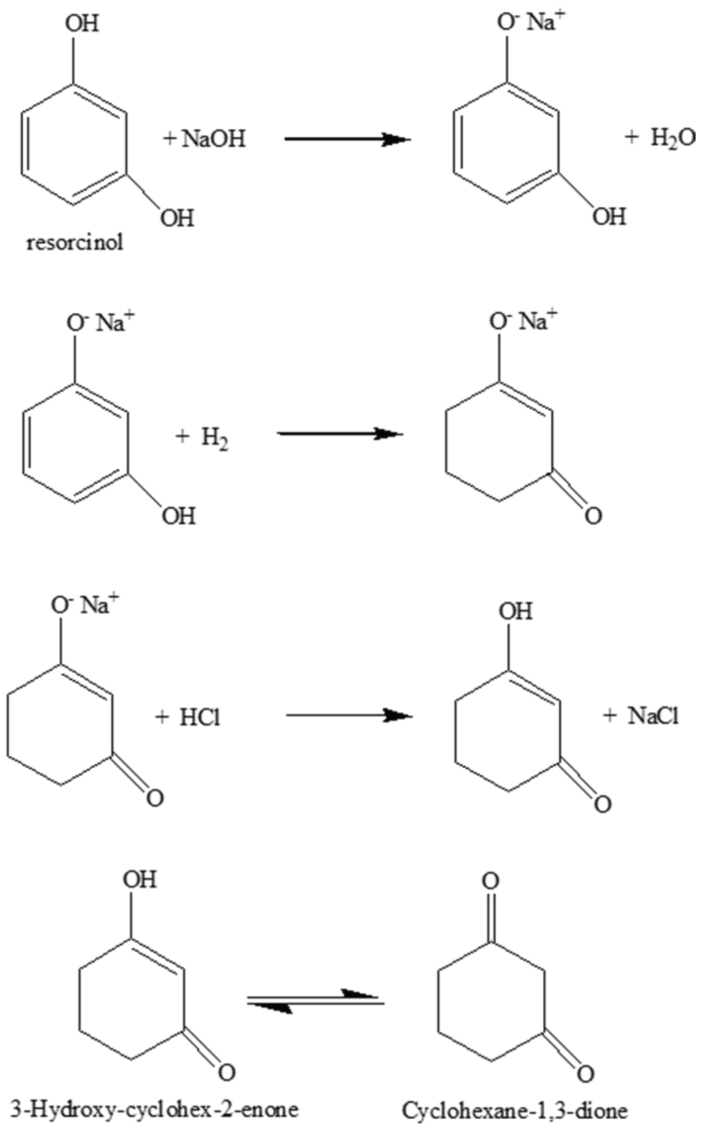
3.1. 1,3-Cyclohexanedione Formation
3.2. Catalyst Screening: Rate of Reaction Over Catalysts
3.2. Reaction Parameters over Ni/Al2O3 Catalyst
4. Preliminary Plant Design
4.1. Design Philosophy
- The selectivity and product quality decline significantly for isothermal run temperatures significantly above 343 K. The by-products leading to poor yield and color were largely derived from the product. The catalyst activity significantly below 333 K was low. The preferred design temperature if 343 ± 5 K is therefore specified.
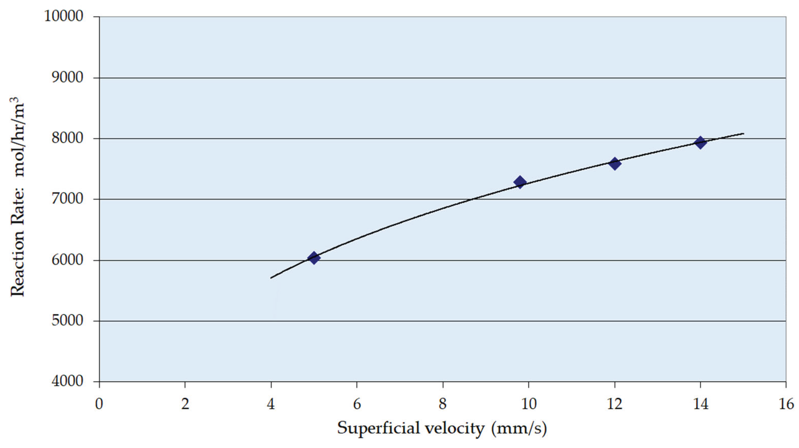
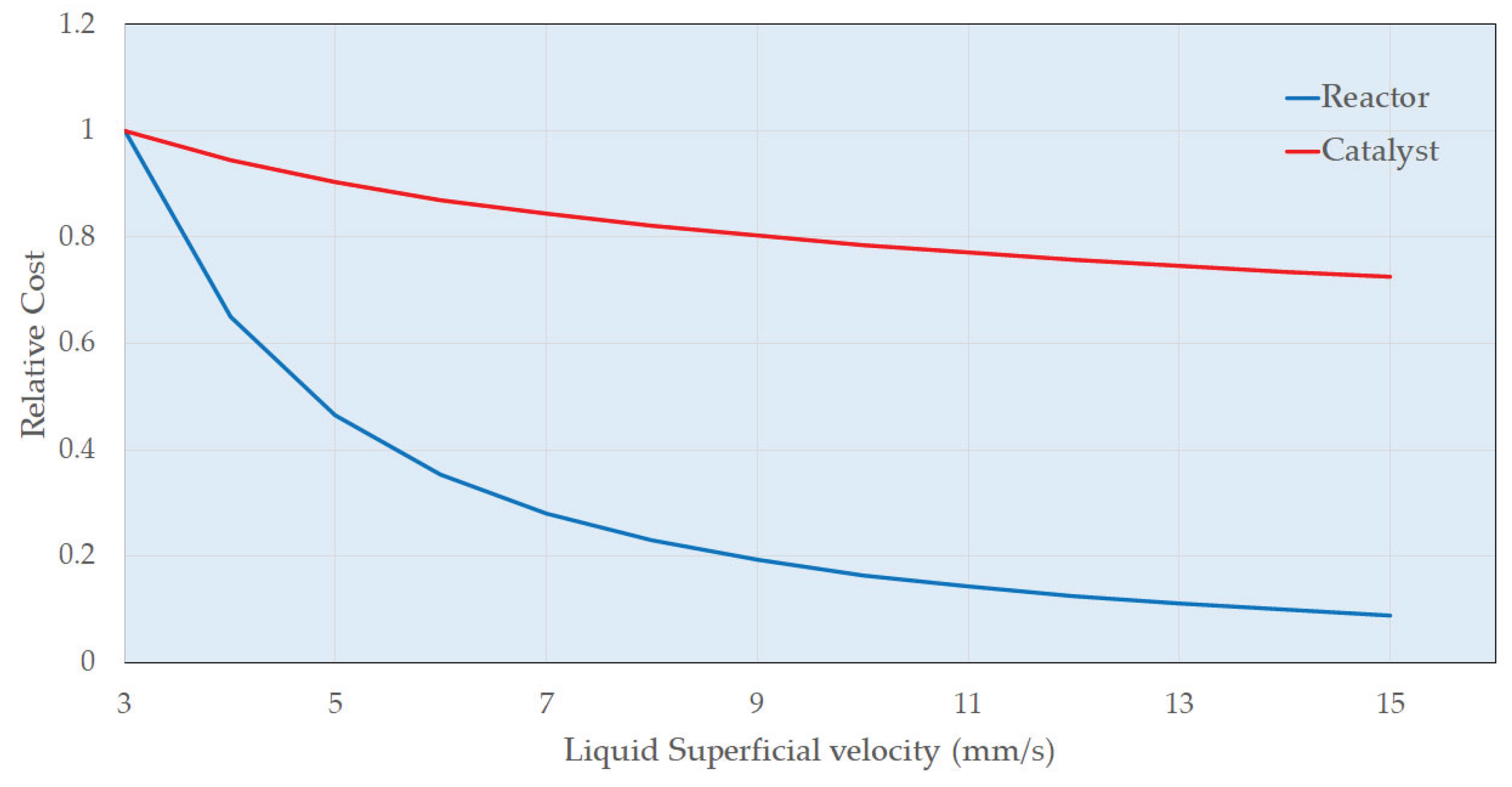
- The enthalpy of reaction is estimated to be 105 kJ mol-1 (exothermic) and there will be a significant adiabatic temperature rise (ca. 80 K). Therefore, cooling must be provided to maintain the temperature largely between 338 and 348 K. Trickle bed reactors themselves are of course essentially adiabatic so the reactor flowsheeting must accommodate this. Adequate mass transfer and reaction rates were obtained in the trickle bed under the selected process conditions; more specifically across the range of liquid mass velocities.
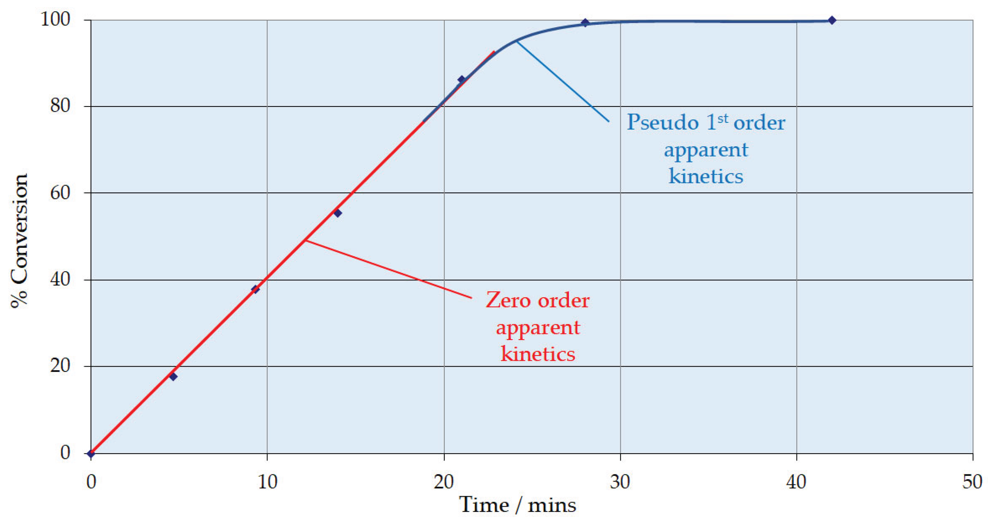
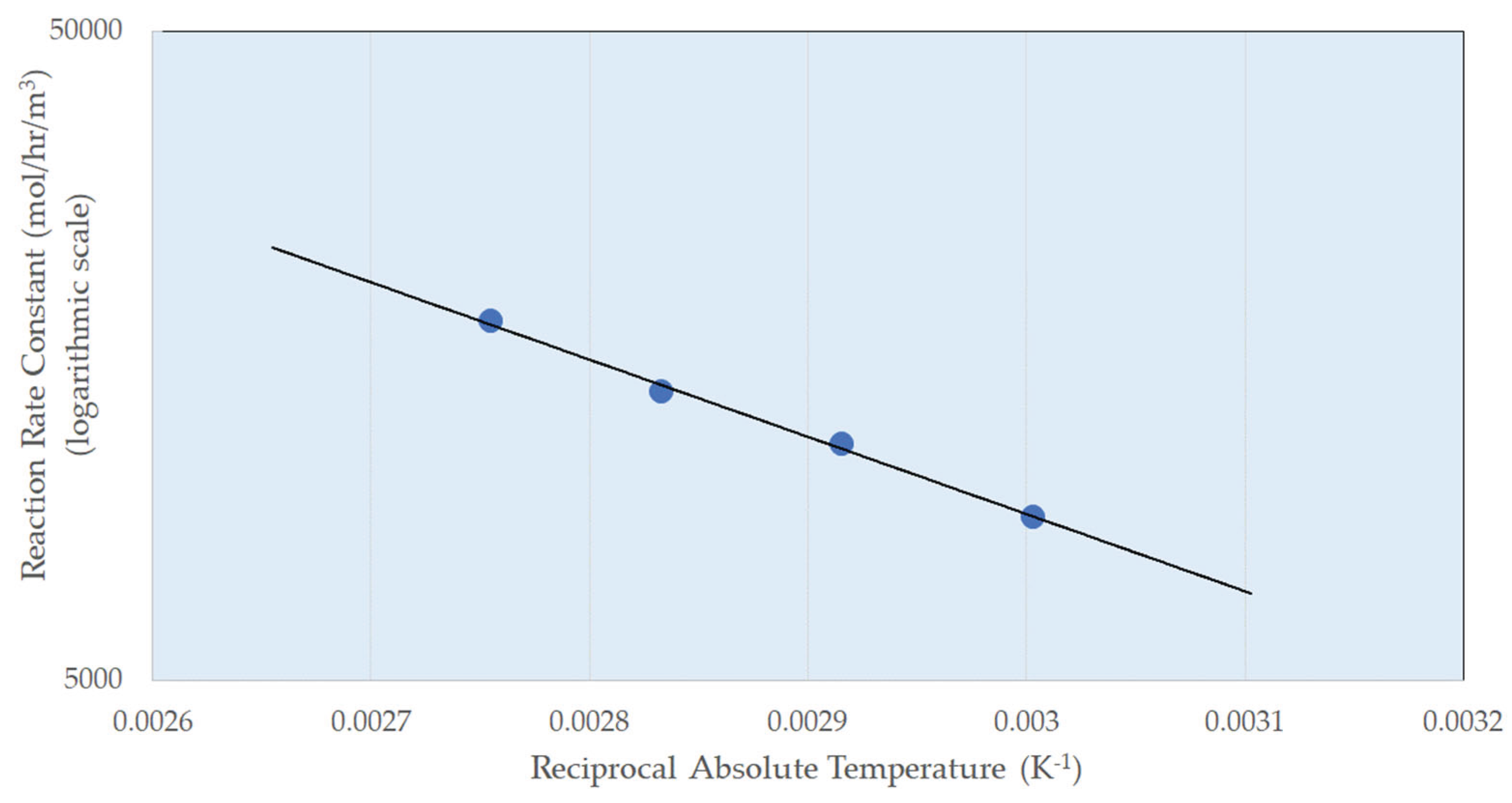
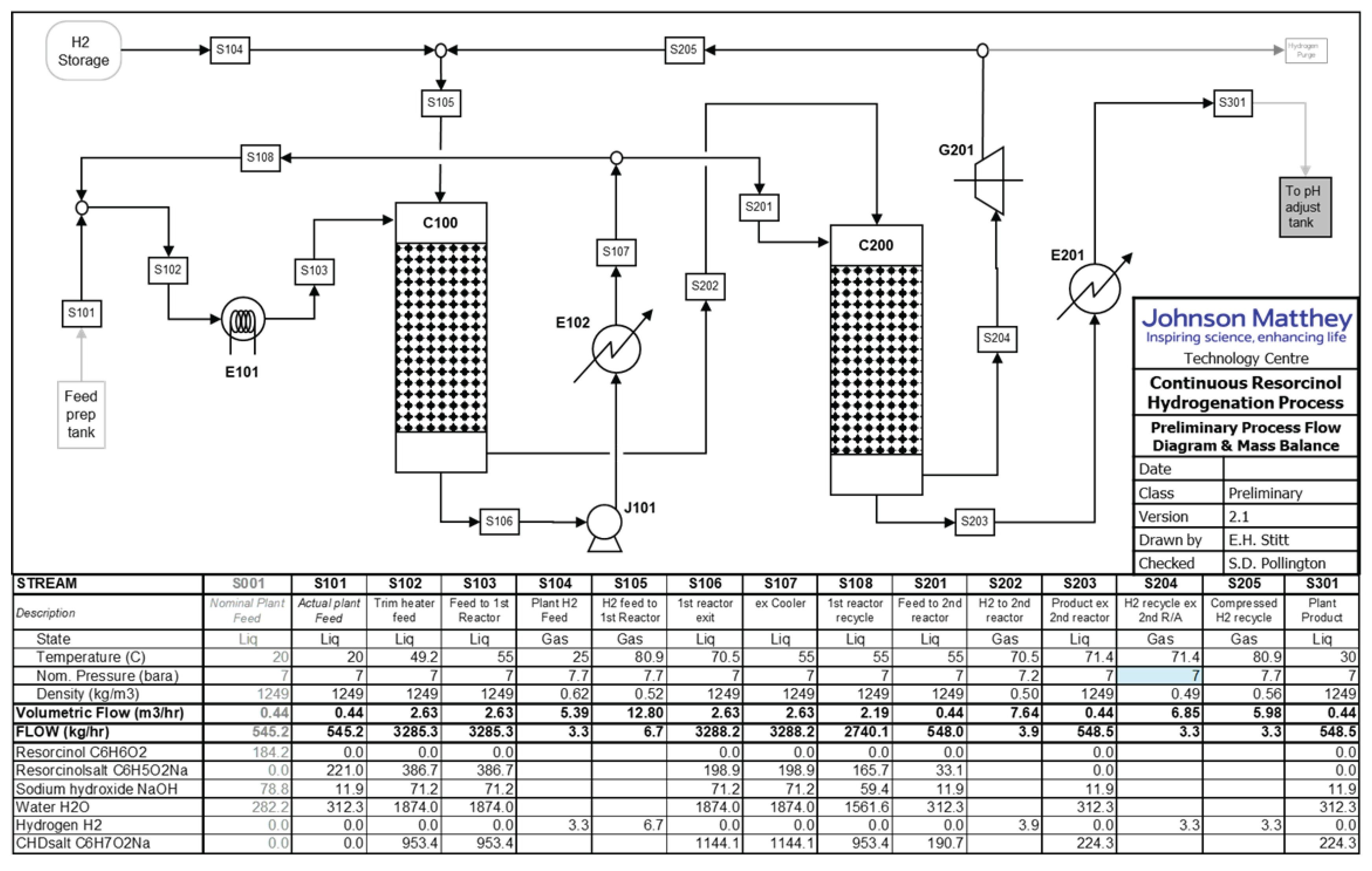
- The zero order behaviour below 85% conversion is fortuitous. This means the same resorcinol reaction is obtained irrespective of its concentration. This affords a solution to the adiabatic temperature rise issue. A first column can be designed to run with recycle to limit pass conversion for the allowable temperature rise.
- A bleed from this recycle loop will be taken forward to a second, single pass column that will take the reaction through to complete conversion, operating in the 1st order reaction rate domain.
4.1. Process Flowsheet
4.2. Main Plant Items
4.3. Preliminary Cost Estimate
4.4. Beyond Preliminary Design
5. Conclusions
Author Contributions
Funding
Data Availability Statement
Acknowledgments
Conflicts of Interest
References
- Brightling, J. Ammonia and the Fertiliser Industry: The Development of Ammonia at Billingham. A history of technological innovation from the early 20th century to the present day. Johnson Matthey Technol. Rev. 2018, 62, 32–47. [Google Scholar] [CrossRef]
- King, M.; Moats, W.; Davenport, W. Sulfuric Acid Manufacture. Analysis, Control and Optimization, 2nd ed.; Elsevier: 2013.
- Brinkmann, T.; Santonja, G.G.; Schorcht. F.; Roudier, S.; Delgado Sancho, L. Best Available Techniques (BAT). Reference Document for the Production of Chlor-alkali. JRC Science and Policy Reports. European Commission, 2014.
- Blacker, A.J.; Breen, J.R.; Bourne, R.A.; Hone, C.A. The Growing Impact of Continuous Flow Methods on the Twelve Principles of Green Chemistry. In Green and Sustainable Medicinal Chemistry: Methods, Tools and Strategies for the 21st Century Pharmaceutical Industry. Summerton, L.; Sneddon, H.F.; Jones, L.C.,: Clark, J.H., Eds. The Royal Society of Chemistry, 2016; Chapter 12, pp 140−155.
- Pollington, S.D. 10th International Symposium on Continuous Flow Reactor Technology for Industrial Applications. Continuous being Implemented for Pharmaceutical Manufacturing with Advantages in EHS, quality and cost. Johnson Matthey Technol. Rev. 2019, 63, 157–165. [Google Scholar] [CrossRef]
- Dilley, G. Continuous Manufacturing at Johnson Matthey For Pharmaceutical Applications. Johnson Matthey Technol. Rev. 2019, 63, 148–149. [Google Scholar] [CrossRef]
- Gutmann, B.; Cantillo, D.; Kappe, C.O. Continuous-Flow Technology-A Tool for the Safe Manufacturing of Active Pharmaceutical Ingredients. Angew. Chem. Int. Ed. 2015, 54, 6688–6728. [Google Scholar] [CrossRef]
- Baumann, M.; Baxendale, I.R. The Synthesis of Active Pharmaceutical Ingredients (APIs) using Continuous Flow Chemistry. Beilstein J. Org. Chem. 2015, 11, 1194–1219. [Google Scholar] [CrossRef] [PubMed]
- Baumann, M.; Moody, T.S.; Smyth, M.; Wharry, S. A Perspective on Continuous Flow Chemistry in the Pharmaceutical Industry. Org. Process Res. Dev, 2020; 24, 1802–1813. [Google Scholar]
- Porta, R.; Benaglia, M.; Puglisi, A. Flow Chemistry: Recent Developments in the Synthesis of Pharmaceutical Products. Org. Process Res. Dev. 2016, 20, 2–25. [Google Scholar] [CrossRef]
- Guan, F.; Kapur, N.; Sim, L.; Taylor, C.J.; Wen, J.; Zhang, X.; Blacker, A.J. A Universal Reactor Platform for Batch and Flow: Application to Homogeneous and Heterogeneous Hydrogenation. React. Chem. Eng. 2020, 5, 1903–1908. [Google Scholar] [CrossRef]
- Calabrese, G.S.; Pissavini, S. From Batch to Continuous Flow Processing in Chemicals Manufacturing. AIChE Journal 2011, 57, 828–834. [Google Scholar] [CrossRef]
- Costandy, J.G.; Edgar, T.F.; Baldea, M. Switching from Batch to Continuous Reactors is a Trajectory Optimization Problem. Ind. Eng. Chem. Res. 2019, 58, 13718–13736. [Google Scholar] [CrossRef]
- Morschhäuser, R.; Krull, M.; Kayser, C.; Boberski, C.; Bierbaum, R.; Püschner, P.A.; Glasnov, T.N.; Kappe, C.O. Microwave-Assisted Continuous Flow Synthesis on Industrial Scale. Green Process Synth. 2012, 1, 281–290. [Google Scholar] [CrossRef]
- Newman, S.G.; Jensen, K.F. The Role of Flow in Green Chemistry and Engineering. Green Chem. 2013, 15, 1456–1472. [Google Scholar] [CrossRef]
- Kashid, M.M.; Kiwi-Minsker, L. Microstructured Reactors for Multiphase Reactions: State of the Art. Ind. Eng. Chem. Res. 2009, 48, 6465–6485. [Google Scholar] [CrossRef]
- Schrickel, J. Continuous Processes - Sustainable Manufacturing. Chemistry Today 2013, 31, 22–25. [Google Scholar]
- Shen, Y.; Maamor, A.; Abu-Dharieh, J.; Thompson, J.M.; Kalirai, B.; Stitt, E.H.; Rooney, D.W. Moving from Batch to Continuous Operation for the Liquid Phase Dehydrogenation of Tetrahydrocarbazole. Org. Process Res. Dev. 2014, 18, 392–401. [Google Scholar] [CrossRef]
- Loh, G.; Tanigawara, R.; Shaik, S.M.; Sa-ei, K.; Wong, L.; Sharratt, P.N. Manufacture of a b-Hydroxyester via a Continuous Reformatsky Process. Org. Process Res. Dev. 2012, 16, 958–966. [Google Scholar] [CrossRef]
- Wong, L.; Wong, R.L.; Loh, G.; Tan, P.E.W.; Teoh, S.K.; Shaik, S.M.; Sharratt, P.N.; Chew, W.; Tan, S.T.; Wang, D. Multikilogram Synthesis of 4-D-Erythronolactone via Batch and Continuous Processing. Org. Process Res. Dev. 2012, 16, 1003–1012. [Google Scholar] [CrossRef]
- Lee, S.L.; O’Connor, T.F.; Yang, X.; Cruz, C.N.; Chatterjee, S.; Madurawe, R.D.; Moore, C.M.V.; Yu, L.X.; Woodcock, J. Modernizing Pharmaceutical Manufacturing: from Batch to Continuous Production. J. Pharm. Innov. 2015, 10, 191–199. [Google Scholar] [CrossRef]
- Halford, B. Process Chemistry: Flow Chemistry Advanced in Industry. C&EN 2017, 95, 23. [Google Scholar]
- Plutschack, M.B.; Pieber, B.; Gilmore, K.; Seeberger, P.B. The Hitchhiker’s Guide to Flow Chemistry. Chem. Rev. 2017, 117, 11796–11893. [Google Scholar] [CrossRef]
- https://thalesnano.com/ accessed 22nd January 2024.
- https://www.vapourtec.com/ accessed 22nd January 2024.
- https://www.uniqsis.com/ accessed 22nd January 2024.
- https://syrris.com/ accessed 22nd January 2024.
- https://www.lonza.com/ accessed 22nd January 2024.
- https://www.corning.com accessed 22nd January 2024.
- https://ehrfeld.com/ accessed 22nd January 2024.
- https://www.chemtrix.com/ accessed 22nd January 2024.
- Holtze, C.; Boehling, R. Batch or Flow chemistry? – A Current Industrial Opinion on Process Selection. Current Opinion in Chemical Engineering 2022, 36, 100798. [Google Scholar] [CrossRef]
- Wietelmann, U.; Gorin, B.; Buzzanca, J.; Quigley, P.; Bourne, S.; Gonzalez, M.A.; Vranceanu, M.; Amann, F.; Wiles, C.; Gauron, G.; et al. Panel Discussion on Flow Chemistry. Chemistry Today 2019, 37, 24–47. [Google Scholar]
- McWilliams, J.C.; Allian, A.D.; Opalka, S.M.; May, S.A.; Journet, M.; Braden, T.M. The Evolving State of Continuous Processing in Pharmaceutical API Manufacturing: A Survey of Pharmaceutical Companies and Contract Manufacturing Organizations. Org. Process Res. Dev. 2018, 22, 1143–1166. [Google Scholar] [CrossRef]
- Stitt, E.H.; Rooney, D.W. Switching from Batch to Continuous Processing for Fine and Intermediate-Scale Chemicals Manufacture. In Novel Concepts in Catalysis and Chemical Reactors: Improving the Efficiency for the Future; Cybulski, A.; Moulijn, J.A.; Stankiewicz, A., Eds.; WILEY-VCH Verlag GmbH & Co.: 2010; Chapter 14, pp 309–330.
- Baker, O. Simultaneous Flow of Oil and Gas. Oil Gas Journal 1954, 53, 185–195. [Google Scholar]
- Sie, S.T.; Krishna, R. Process Development and Scale Up: III. Scale-up and scale down of Trickle Bed Processes. Rev. Chem. Eng 1998, 14, 203–252. [Google Scholar] [CrossRef]
- Enache, D.I.; Landon, P.; Lok, C.M.; Pollington, S.D.; Stitt, E.H. Direct Comparison of a Trickle Bed and a Monolith for Hydrogenation of Pyrolysis Gasoline. Ind. Eng. Chem. Res. 2005, 44, 9431–9439. [Google Scholar] [CrossRef]
- Al-Dahhan, M.H.; Wu, Y.; Dudukovic, M.P. Reproducible Technique for Packing Laboratory Scale Trickle Bed Reactors with a Mixture of Catalyst and Fines. Ind. Eng. Chem. Res. 1995, 34, 741–747. [Google Scholar] [CrossRef]
- Al-Dahhan, M.H.; Dudukovic, M.P. Catalyst Bed Dilution for Improving Catalyst Wetting in Laboratory Trickle-bed Reactors. AIChE Journal 1996, 42, 2594–2606. [Google Scholar] [CrossRef]
- Kulkarni, R.R.; Wood, J.; Winterbottom, J.M.; Stitt, E.H. Effect of Fines and Porous Catalyst on Hydrodynamics of Trickle Bed Reactors. Ind. Eng. Chem. Res. 2005, 44, 9497–9501. [Google Scholar] [CrossRef]
- Bavykin, D.V.; Lapkin, A.A.; Kolaczkowski, S.T.; Plucinski, P.K. Selective Oxidation of Alcohols in a Continuous Multifunctional Reactor: Ruthenium Oxide Catalysed Oxidation of Benzyl Alcohol. Appl. Catal. A: Gen. 2005, 288, 175–184. [Google Scholar] [CrossRef]
- Plucinski, P.K.; Bavykin, D.V.; Kolaczkowski, S.T.; Lapkin, A.A. Application of a Structured Multifunctional Reactor for the Oxidation of a liquid Organic Feedstock. Catal. Today 2005, 105, 479–483. [Google Scholar] [CrossRef]
- Plucinski, P.K.; Bavykin, D.V.; Kolaczkowski, S.T.; Lapkin, A.A. Liquid-Phase Oxidation of Organic Feedstock in a Compact Multichannel Reactor. Ind. Eng. Chem. Res. 2005, 44, 9683–9690. [Google Scholar] [CrossRef]
- van Herk, D.; Kreutzer, M.T.; Makkee, M.; Moulijn, J.A. Scaling Down Trickle Bed Reactors. Catal. Today 2005, 106, 227–232. [Google Scholar] [CrossRef]
- van Herk, D.; Castaño, P.; Makkee, M.; Moulijn, J.A.; Kreutzer, M.T. Catalyst Testing in a Multiple-parallel, Gas–Liquid, Powder-packed bed Microreactor. Appl. Catal. A: Gen. 2009, 365, 199–206. [Google Scholar] [CrossRef]
- Krishnamurthy, S.; Peles, Y. Surface Tension effects on Adiabatic gas–liquid flow across micro pillars. Int. J. Multiphase Flow 2009, 35, 55–65. [Google Scholar] [CrossRef]
- Spadoni, C.; Jones, R.V.; Urge, L.; Darvas, F. Scaling up and Validation of Hydrogenation reactions using a Continuous-flow Microfluidics-based reactor, H-Cube®. Chemistry Today 2006, January/February 38-41.
- Szöllösi, G.; Hermán, B.; Fülöp, F.; Bartók, M. Continuous enantioselective hydrogenation of activated ketones on a Pt-CD chiral catalyst: use of H-Cube reactor system. Reaction Kinetics and Catalysis Letters 2006, 88, 391–398. [Google Scholar] [CrossRef]
- Hickman, D.A.; Weidenbach, M.; Friedhoff, D.P.A. Comparison of a Batch Recycle Reactor and an Integral Reactor with Fines for Scale-up of an Industrial Trickle Bed Reactor from Laboratory Data. Chem. Eng. Sci. 2004, 59, 5425–5430. [Google Scholar] [CrossRef]
- Papayannakos, N.; Marangozis, J. Kinetics of Catalytic Hydrodesulfurization of a Petroleum Residue in a Batch Recycle Trickle Bed Reactor. Chemical Engineering Science 1984, 39, 1051–1061. [Google Scholar]
- Qiwee, G.; Zhihou, M.; Yumin, Z. The Experimental Investigation of Catalytic Reaction Processes in Trickle Beds. J. Chem Industry & Eng. (China), 1986; 1, 120–127. [Google Scholar]
- Berger, R.J.; Stitt, E.H.; Marin, G.B.; Kapteijn, F.; Moulijn, J.A. Chemical Reaction Kinetics in Practice. CATTECH 2001, 5, 30–60. [Google Scholar] [CrossRef]
- Pollington, S.D.; Enache, D.I.; Landon, P.; Meenakshisundaram, S.; Dimitratos, N.; Wagland, A.; Hutchings, G.J.; Stitt, E.H. Enhanced Selective Glycerol Oxidation in Multiphase Structured Reactors. Catalysis Today 2009, 145, 169–175. [Google Scholar] [CrossRef]
- Enache, D.I.; Hutchings, G.J.; Taylor, S.H.; Natividad, R.; Raymahasay, S.; Winterbottom, Stitt, E.H. Experimental Evaluation of a Three-Phase Downflow Capillary Reactor. Ind. Eng. Chem. Res. 2005, 44, 6295–6303. [Google Scholar] [CrossRef]
- Enache, D.I.; Hutchings, G.J.; Taylor, S.H.; Raymahasay, S.; Winterbottom, J.M.; Mantle, M.D.; Sederman, A.J.; Gladden, L.F.; Chatwin, C.; Symonds, K.T.; Stitt, E.H. Multiphase Hydrogenation of Resorcinol in Structured and Heat Exchange Reactor Systems. Influence of the Catalyst and the Reactor Configuration. Catalysis Today 2007, 128, 26–35. [Google Scholar] [CrossRef]
- Enache, D.I.; Thiam, W.; Dumas, D.; Ellwood, S.; Hutchings, G.J.; Taylor, S.H.; Hawker, S.; Stitt, E.H. Intensification of the solvent-free catalytic hydroformylation of cyclododecatriene: Comparison of a stirred batch reactor and a heat-exchange reactor. Catalysis Today 2007, 128, 18–25. [Google Scholar] [CrossRef]
- Allison, M.; Bergquist, A.M.; Madison Bertoch, M.; Gildert, G.; Strathmann, T.J.; Werth, C.J. Catalytic Denitrification in a Trickle Bed Reactor: Ion Exchange Waste Brine Treatment. Journal AWWA 2017, 109, E129–E151. [Google Scholar]
- Kaplan, R.; Erjavec, B.; Senila, M.; Pintar, A. Catalytic wet air oxidation of bisphenol A solution in a batch-recycle trickle-bed reactor over titanate nanotube-based catalysts; Environ. Sci. Pollut. Res. 2014, 21, 11313–11319. [Google Scholar] [CrossRef]
- Shen, Y.; Maamor, A.; Abu-Dharieh, J.; Thompson, J.M.; Kalirai, B.; Stitt, E.H.; Rooney, D.W. Moving from Batch to Continuous Operation for the Liquid Phase Dehydrogenation of Tetrahydrocarbazole. Org. Proc. Res. Dev. 2014, 18, 392–401. [Google Scholar] [CrossRef]
- Hou, X.; Xu, L.; Wei, Z.; Liu, X.; Li, X.; Deng, S. Reaction Process and Kinetics of the Selective Hydrogenation of Resorcinol into 1,3-Cyclohexanedione. Journal of the Taiwan Institute of Chemical Engineers 2014, 45, 1428–1434. [Google Scholar] [CrossRef]
- Lim, M.H.M.; Sederman, A.J.; Gladden, L.F.; Stitt, E.H. New insights to Trickle and Pulse Flow Hydrodynamics in Trickle-Bed Reactors using MRI. Chem. Eng. Sci. 2004, 59, 5403–5410. [Google Scholar] [CrossRef]
- Gladden, L.F.; Anadon, L.D.; Lim, M.H.M.; Sederman, A.J.; Stitt, E.H. Insights into the Mechanism of the Trickle-to-Pulse Transition in Trickle-Bed Reactors. Ind. Eng. Chem. Res. 2005, 44, 6320–6331. [Google Scholar] [CrossRef]
- Pollington, S.D.; Dingwall, L.D.; Collier, P.J.; Stitt; E.H. Comparison of Reactors for 2-Hydroxy Benzyl Alcohol Oxidation over Pt/Bi/Al2O3 Fixed Catalyst. Presentation at Joint Event Catalysis in Multiphase Reactors CAMURE-8 International Symposium on Multifunctional Reactors ISMR-7, May 2011.
- Ulrich, G.D. A Guide to Chemical Engineering Process Design and Economics; John Wiley & Sons, Inc. 1988.
- De la Mare, R.F. Manufacturing Systems Economics; Holt Reinhart and Winston, 1982.
- Teoh, S.K.; Rathi, C.; Sharratt, P. Practical Assessment Methodology for Converting Fine Chemicals Processes from Batch to Continuous. Org. Process Res. Dev. 2016, 20, 414–431. [Google Scholar] [CrossRef]
- Gerogiorgis, D.; Jolliffe, H.G. Continuous Pharmaceutical Process Engineering and Economics: Investigating Technical Efficiency, Environmental Impact and Economic Viability. Chemistry Today 2015, 33, 29–32. [Google Scholar]
- Kockmann, N. Modular Equipment for Chemical Process Development and Small-Scale Production in Multipurpose Plants. ChemBioEng. 2016, 3, 5–15. [Google Scholar] [CrossRef]
- Hickmann, D.A.; Holbrook, M.T.; Mistretta, S.; Rozeveld, S.J. Successful Scale-up of an Industrial Trickle Bed Hydrogenation Using Laboratory Reactor Data. Ind. Eng. Chem. Res. 2013, 52, 15287–15292. [Google Scholar] [CrossRef]
- Spencer, M.S. Fundamental Principles. In Catalyst Handbook. Twigg, M.V. Ed. Wolfe Publishing Ltd., 2nd Edition, 1989; Chapter 1, pp 17–84.
- Ishitani, H.; Saitom, Y.; Laroche, B.; Rao, X.; Kobayashi, S. Recent Perspectives in Catalysis under Continuous Flow. In Flow Chemistry: Integrated Approaches for Practical Applications. Luis, V.L.; Garcia-Verdugo, E., Eds. The Royal Society of Chemistry, 2020, Chapter 1, pp 1–49.
| Form | Cylinder | Pellet | Extrudate | Trilobe |
| Diameter | 1.2 mm | 3 mm | 1-3 mm | 2.5 mm |
| Length | 3-7 mm | 3 mm | 1-4 mm | 2.8 mm |
| BET Surface Area | 960 m2 g-1 | 130 m2 g-1 | 1000 m2 g-1 | 110 m2 g-1 |
| Metal content | 2 wt. % Pd | 5 wt. % Pd | 0.4 wt.% Rh | 22 wt. % Ni |
| Support | Carbon | Alumina | Carbon | Alumina |
| Catalyst Volume / cm3 | Temperature / K | Pressure / barg | Liquid Superficial Velocity / mm s-1 | Gas:Liquid Ratio |
| 140 | 333 - 363 | 5 - 9 | 6 - 14 | 1:1 |
| Catalyst |
mmol h-1 gcat-1 |
Apparent Rate mmol h-1 gmetal-1 |
mmol h-1 mcat-3 |
| 2%Pd/C | 3 | 147 | 15 |
| 5%Pd/Al2O3 | 1.4 | 68 | 16 |
| 0.4%Rh/C | 6.6 | 1640 | 35 |
| 22%Ni/Al2O3 | 19 | 91 | 164 |
| 2%Pd/C | 3 | 147 | 15 |
Disclaimer/Publisher’s Note: The statements, opinions and data contained in all publications are solely those of the individual author(s) and contributor(s) and not of MDPI and/or the editor(s). MDPI and/or the editor(s) disclaim responsibility for any injury to people or property resulting from any ideas, methods, instructions or products referred to in the content. |
© 2024 by the authors. Licensee MDPI, Basel, Switzerland. This article is an open access article distributed under the terms and conditions of the Creative Commons Attribution (CC BY) license (http://creativecommons.org/licenses/by/4.0/).


