Preprint
Article

Renovation Wave for Europe: Low-Carbon Design in Refurbishment of Social Housing in Southern Italy

Altmetrics

Downloads

73

Views

24

Comments

0

A peer-reviewed article of this preprint also exists.

This version is not peer-reviewed

Submitted:

28 March 2024

Posted:

29 March 2024

You are already at the latest version

Alerts
Abstract
Public housing stock, called Social Housing, in Italy developed between the 1950s and the 1980s. As of today, the first residential developments are almost nearing their end-of-life age, in need of urgent and intensive renovation. The European Commission, with the Renovation Wave, has set a goal of doubling the rate of building renovation over the next 10 years, reducing emissions, improving energy performance, and promoting decarburization. Renovation interventions, including structural, functional, energy, plant upgrading, etc., are to be preferred over integral demolition and reconstruction interventions, which have significant repercussions in terms of managerial and social discomfort. The case studies examined concern renovation interventions aimed at energy efficiency, functional adaptation of housing as well as facade restyling. The design variants analyzed were evaluated in terms of CO2e emissions, according to LCI (Life Cycle Inventory) and EPD (Environmental Product Declaration) approaches. This approach has a twofold purpose: to propose design guidelines, with low CO2e emissions, through hypotheses of variants to the case studies, and to propose, to the Economic Operators, economically advantageous bidding scenarios, in the procurement process.
Keywords: 
Subject: Engineering  -   Architecture, Building and Construction

1. Introduction

On March 14, 2023, the European Parliament approved the revision of the European EPBD [1], which is necessary to realize the renovation wave, i.e., a wave of renovations of more than 35 million buildings and the creation of up to 160,000 jobs in the construction sector. Renovation of public and private buildings was identified in the European Green Deal as a key initiative to promote energy efficiency in the sector and achieve the goals. The Renovation Wave aims to at least double the annual rate of energy renovation by 2030 and, in addition to reducing emissions and creating green jobs in the construction sector, which is dominated by local businesses, will improve the overall living standards of Europeans. The Renovation Wave initiative is based on the National Long-term Building Renovation Strategy, other aspects of the Energy Performance of Buildings Directive, and the buildings aspects of each EU country’s National Energy and Climate Plans (NECPs). The strategy identifies 3 areas of focus:
-
Tackling energy poverty and worst-performing buildings.
-
Redevelopment of public buildings.
-
Decarburization of heating and cooling.
With some 40 million Europeans unable to afford to adequately heat their homes in 2022, renovations will help address energy poverty. They can improve the health and well-being of vulnerable people while reducing their energy bills-as outlined in the Commission’s 2020 Recommendation on Energy Poverty, which was part of the Renovation Wave initiative-and subsequently also highlighted in the Commission’s Recommendation on Energy Poverty, published in October 2023.

2. State-of-the-Art

Intervening on the existing building is a necessity dictated by different urgencies that generally start from simple and individual reasons, described by Alberto Alessi as follows: “One builds on the built simply because it is economically advantageous to exploit the work already done by others; or because it is impossible to obtain sufficient permits or building indices to carry out new construction in desirable areas such as those where ‘historic’ buildings are often located. Other times one decides to adapt the existing for personal reasons, to save the family home as a piece of one’s history that one does not want to lose; or for collective reasons, when intervening on the existing turns out to be the only way to revive and give permanence to the cultural memory crystallized in the buildings, without making them sterile museum objects.” [2]. The urgencies become more complex when including energy-environmental, ecosystem and psychophysical well-being needs. Intervening on the existing built environment can therefore become a unique opportunity to improve the performance of the building and its context especially if quality standards are raised to equal those of new construction, if energy performance is improved and the overall functionality of the building is enhanced, and if, with reference to public housing, new patterns of contemporary living and new user profiles are taken as the data for redesign. In many European cities, this strategy has already started a few decades ago through densification operations (vs. sprawl), aimed at increasing the volume, at the same time as upgrading the existing, particularly on the energy level. In this regard, Laura Daglio writes as follows: “Faced, in fact, with a need for densification of urban areas, as a reaction to the growing estimates about the future urbanized population, with the aim of minimizing land consumption, the use of existing cover and interstitial and residual spaces as new soil represents a possible strategy, also because it makes it possible to intervene by intensifying urban fabrics, proposing and placing new functions, including temporary ones, experimenting with possible social mix solutions, suggesting new keys to interpreting the existing, even degraded, that outline possible paths for its redevelopment and revitalization. [...] Intervention in roofing also meets the demand for sustainability in cities, not only because it represents the ideal location of plants for the production of electricity and heat or for the set of advantages that result from the transformation of solar slabs into roof gardens, but also because of new forms of concession of private property, which allude, for example, to the exchange of building land on the roof, in exchange for an intervention of energy upgrading of the entire building below.” [3].
The same principles are reiterated in Reale’s (2008) research [4]: “Returned to great interest as an antithetical model to that of the diffuse city, the compact city aims to counteract the effects due precisely to the diffusive phenomena, such as excessive land consumption, urban congestion phenomena, rising infrastructure costs, and worsening population health conditions, which have characterized settlement development during the last century and are no longer sustainable today. Densification policies are proposed as credible practices to achieve sustainability goals, such as reducing energy consumption and climate-changing gas emissions, considering that more than half of the world’s population resides in cities and large metropolitan areas, moreover, which are continuously growing: experiments in re-stitching, completions, grafting and “infill,” densification techniques and “anti-sprawl” strategies are extensively documented in the recent experiences of Bjilmermeer in Amsterdam, Technopark in Zurich, and Karl Marx Alee in Berlin. These experiences are not limited to the definition of simple measures preordained to increase urban density tout court, but are intended to shape growth based on transformations aimed at raising the level of quality of the built environment through the integration of new performances (energy, structural, plant engineering, etc.), as well as with the introduction of appropriate functional mixes and the provision of suitable levels of ecological and environmental endowments” (Ferrante et al., 2012) [5]. In this direction, “[…] if our epoch is one of respite in expansion and cities no longer need to grow and expand, the theme of critical rethinking on the “already done” acquires a decisive ethical and cultural value since it modifies the very idea of progress. This notion can no longer be automatically related to the idea of development and growth, as Pasolini had already specified in a premonitory essay […], but rather to that of a deeper sense of civilization and responsibility. Therefore, no longer accumulation, expansion, consumption and spasmodic competitiveness, but rationalization and meekness, saving, repair, integration” (Spagnolo, 2014) [6]. Operating on the existing is an ever-present action in the history of cities and “[…] means respecting the identity of places and operating on the city by successive stratifications, as has always been the case in the history of European cities, using pre-existing structures as the foundation for new ones” (Calzolaretti, 2014) [7]. In essence, according to a well-established view, it is a field that includes actions of preservation and restoration of assets of historical and artistic interest; however, today this view is limiting if extended to the whole city because, also in the wake of ecological thinking and the limits manifested by the recent building stock, actions on the existing also and above all contemplate actions of rehabilitation and redevelopment that concern a large number of buildings constructed in the last fifty years in urban suburbs.
From the analysis of the literature, the redevelopment strategies that predominantly emerge are:
-
Building replacement, a radical operation involving the demolition of the existing built-up area and new construction; it is the extreme ratio, to be applied when there are no physical and social prerequisites and requirements such that an artifact can be reused over time. This option is often considered suitable for the suburbs [8], where, for some, it seems that the “principle of erasure and rapid replacement should prevail rather than that of durability, that is, of the city building on itself over time, on its footprints and morphological traces” (Valente, 2014) [9]. Building replacement poses the problem of disposing of those non-de-constructible structures that produce waste, as well as the erasure of the intangible heritage of architectural design experience, often never completed, and the identity heritage that has been formed over time.
-
Construction on the built, an operation that results in layering and overlaying on the existing built; the image of the Theatre of Marcellus in Rome or the Roman theater in Lecce and so many other historic buildings testify to how historically the practice of building on the built has always been used, how it belongs to the history of architecture and the history of cities, even those that would seem to have stabilized over time at a given historical epoch. Some of Herzog&de Meuron’s projects, including the aforementioned Hamburg Philharmonic, are indicative. “Regarding the city in which degraded and abandoned areas are multiplying, an awareness of working is maturing that brings back to the center of the practice of architectural and urban design the theme of building on the built, and which is accompanied by an extended critical attention to the notion of heritage (not only from the side of protection practices) and the common good” (Valente 2014) [10].
-
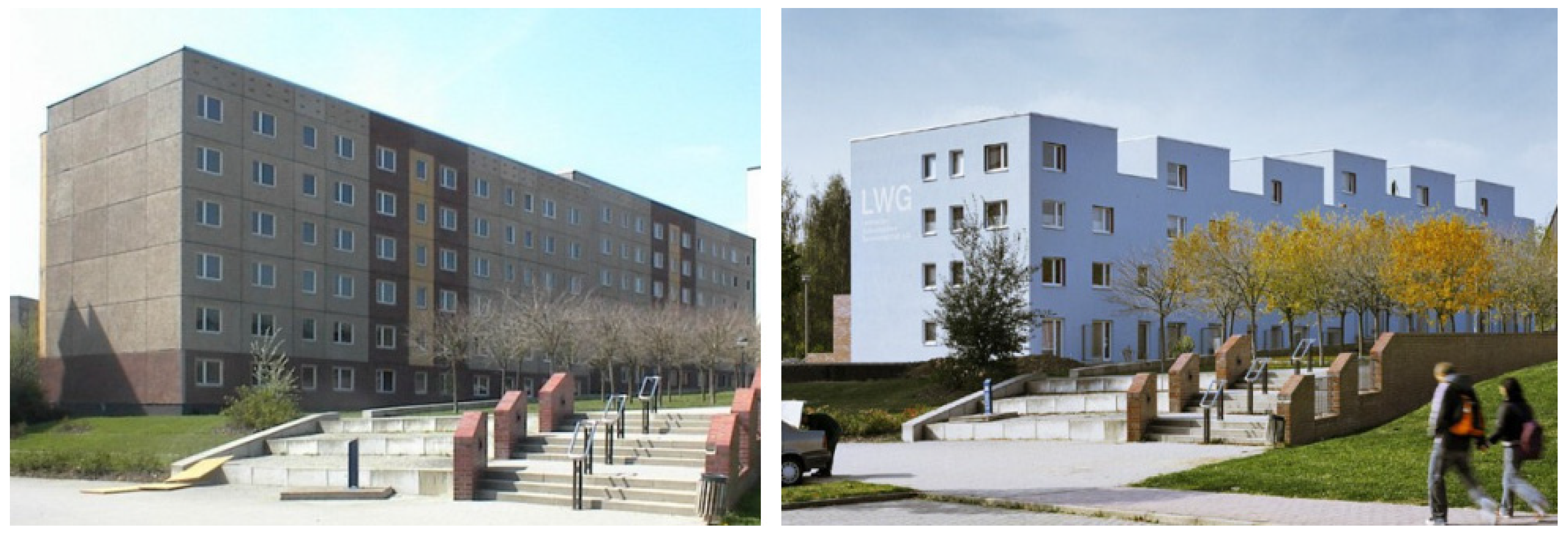
Transformation, more or less profound, an operation that produces results of different intensities in which volumetric addition and subtraction play a fundamental role, practiced according to different criteria, intensities and dimensions (Figure 1 and Figure 2). The need for the built environment to be alive is evidenced by a huge built heritage that over the centuries has undergone profound transformations on a morphological, typological and functional level: traditional architectures and buildings have welcomed changes of all kinds, contributing to their preservation over time, even taking on sometimes completely different connotations. By this process, they have enabled the transmission of the building artefact, which, if no longer used due to inability to perform certain functions or inadequate with respect to contemporary needs in terms of energy, technology, function and morphology, would have decayed or become an archaeological find. “The present condition of the urban building stock, especially in Europe, at a time of impending economic crisis of which no reasonable conclusion is in sight, has made transformation one of the few feasible programs by which an attempt is made to combat the waste that played a decisive part in triggering the crisis, waste of energy, time, and resources of all kinds due to the unnecessary movement of men and goods and the unlimited production of waste, the difficult accessibility of urban services, and the distance between residences and places of work [... ] Architecture is continuously transformed by those who design and build it; but it is also true that, considering it as an expression of the society and culture of a given time, it must be admitted that it seems, in its continuous modification, something similar to a living organism that undergoes continuous metamorphoses, especially if one accepts of this last word the biological meaning that usually refers to relevant and conspicuous transformations, as it happens for example in reptiles or worms that become butterflies” (Portoghesi 2012) [11]. There are interventions that contemplate re-functionalization, understood as an intervention designed to give a new destination compatible with the context. The example of the residential transformation of the gasometers in Vienna, as described in an article, is given in this regard: “The most important redevelopment intervention, which still represents one of the finest examples of rehabilitation, took place in Vienna in the 1990s, and the dynamism of the project suggests that there may be further developments in the coming years. Built in 1896 in the Viennese district of Simmering, a central area of the Austrian capital, the “Gasometres” (name declined in the plural because the plant-the largest in Europe-was made up of four structures) was decommissioned in 1984. Declared a national monument, the gasometer was used in various ways and by various entities for ten years until the city of Vienna decided in 1995 to hold an international design competition to restore the four monuments. A rather ‘open’ call for new ideas, with the only restriction on the intended use: residential, with attached services. And, it goes without saying, the preservation of the original external structure, except for the possibility of creating small openings in the wall face such, however, as not to compromise the original decorations. For gasometers A, B and C are chosen respectively: a renowned designer such as Jean Nouvel (whose ‘touch’ is evident in the creation of a covered plaza with a translucent roof that, through a play of refractions, synthesizes the old-new combination) and two Austrian firms, Coop Himmelbau (creator of the addition of three volumes to the existing facade) and Manfred Wedhorn, which adopted the more “green” approach, adding terraces and interior gardens. The design of Gasometer D, on the other hand, is awarded to architect Wilhelm Holzbauer, winner of a specific open competition for ideas.” [12]. Other cases, on the other hand, shown below through images, represent interventions in the transformation of buildings and contexts that originally arose with a residential destination that, during redevelopment, retained the same destination. It is precisely on these types of interventions that the research dwells, with the aim of examining how, around the residential functional constant, morphological variables can be grafted according to criteria of eco-sustainability and functional, spatial and aesthetic-formal quality.

3. Tools and Methods

Life Cycle Assessment (LCA) methodology is a popular and shared tool for evaluating the most sustainable design choices. To mitigate environmental impacts, it is necessary to focus on a comprehensive view of the building organism based on its entire life cycle, with reference to the reduction of embodied energy in building materials. The latter (Embodied Energy - EE) is considered the energy needed at all stages of life, from cradle to grave, suffice it to say that embodied energy is 40 percent of the total energy for a building with a lifespan of 50 years. Manufacturers in the construction industry are also required to have environmental certifications of construction products (ISO14025), implementing the product with life cycle inventory data, i.e., carbon footprint. The study, as a whole, focuses on identifying design choices (morphological, spatial, technological, materials) with lower environmental impact.
The goal of the research is to reduce CO2e emissions by at least 55% compared to a base-line scenario. For methodological development, the tools used are reference to BS EN 15978:2011 -Sustainability of construction works - Assessment of environmental performance of buildings - Calculation method [13] Figure 3. With reference to the Figure 1, the modules under study are: A1, A2, A3 (Production phases); C1, C2, C3, C4 (End-of-life phases); D (Post-end-of-life benefits).
-
Module ‘A’ is mainly inherent to the choice of materials; the database used for this phase (from cradle to gate) is the University of Bath’s Inventory Carbon&Energy (ICE) [14]. In the case of composite products, reference was made to the EPD (Environmental Product Declaration) inventory.
-
Module ‘C’ includes deconstruction of the building and transportation of materials to disposal or recovery/recycling sites. Emissions reported in the data sheets of demolition equipment, and their time of use, were used to calculate the EC.
-
Module ‘D’ includes impacts/benefits associated with demolition, transportation, and waste disposal/treatment. Potential positive impacts however can be obtained from reuse and recycling after end of life.
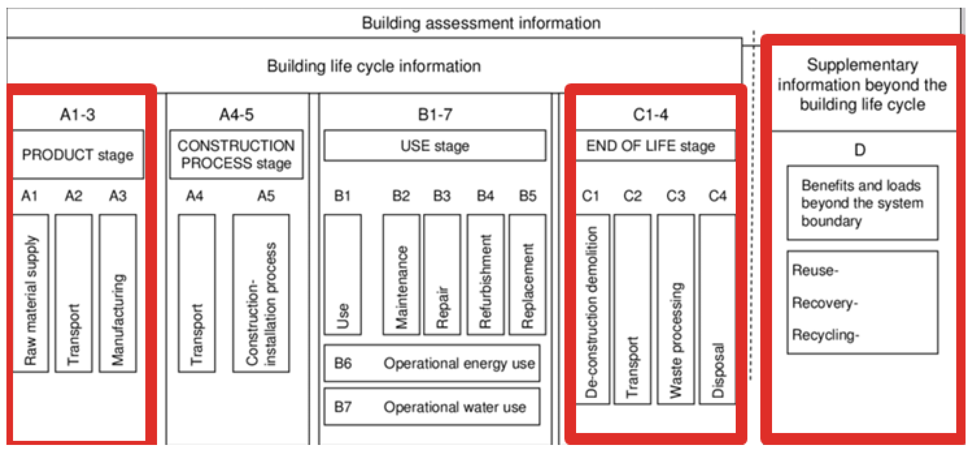
Figure 3. BS EN 15978:2011 - Sustainability of construction works—Assessment of environmental performance of buildings—Calculation method.
Preprints 102547 g003

3.1. Concept Design

Technological retrofit interventions generally take place through four main actions on the existing building: replacement, integration, addition, and subtraction (Figure 4):
-
replacement involves the replacement of functional elements or parts with others of superior performance or new performance, not guaranteed by the original elements;
-
integration concerns the addition of building elements to existing parts such as sub-systems or building components, parts that are not removed but remain in situ and are, possibly, subject to maintenance and restoration, with the purpose of increasing existing performance or adding new performance;
-
addition concerns the action aimed at adding technical elements, parts of buildings or entire volumes to the building, as an extension of the original building (Figure 5);
-
final subtraction concerns the action aimed at eliminating technical elements, factory parts or entire volumes, in order to achieve new or higher performance, due to the new configuration of the building.
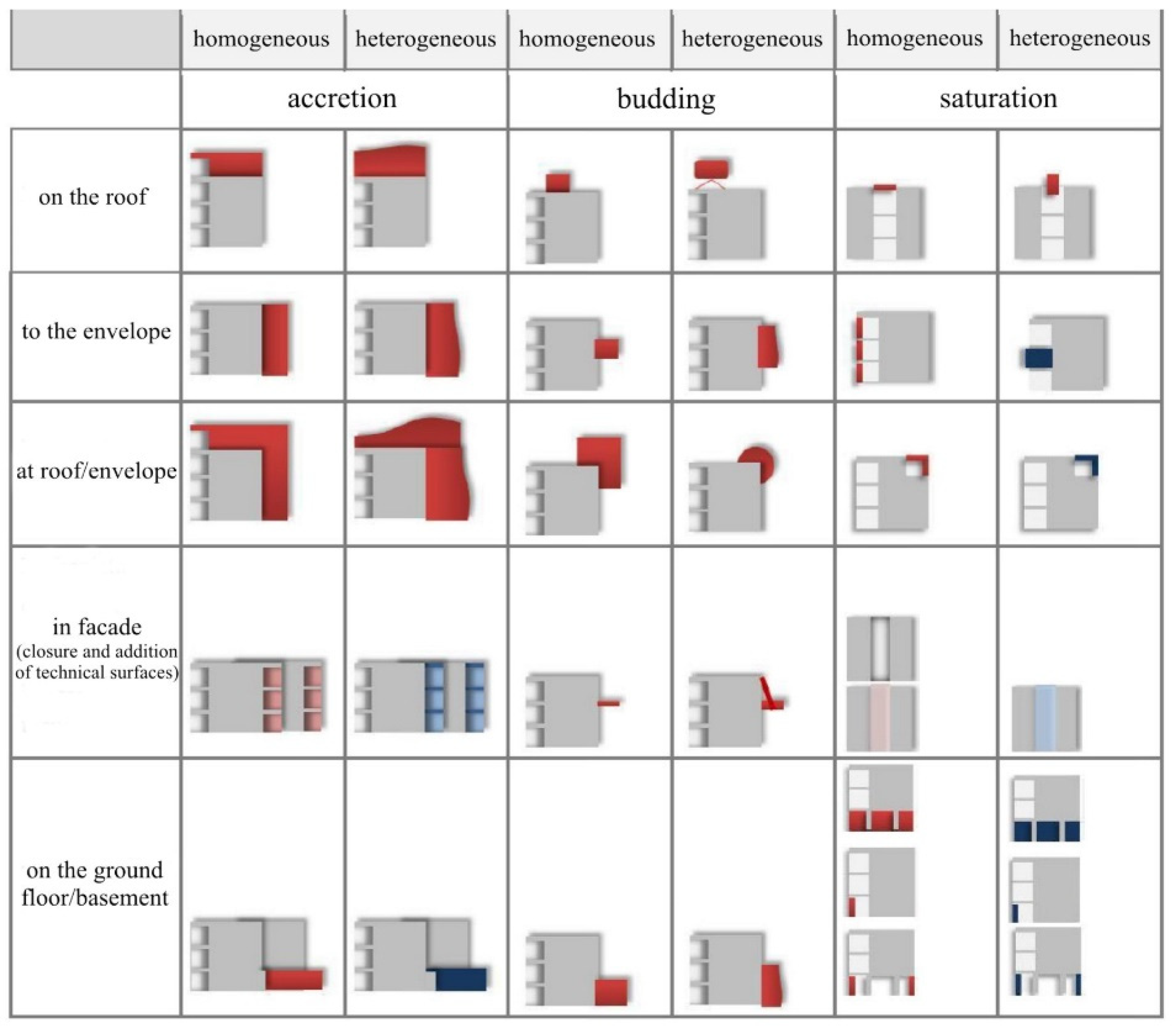
Figure 4. Classification of interventions (by accretion, budding, and saturation) in facade, roof, and footing (source: Luisa Califano, 2011).
Preprints 102547 g004
Figure 5. Addition models (source: Sara Parlato 2014).
Preprints 102547 g005

3.2. Construction Scenarios

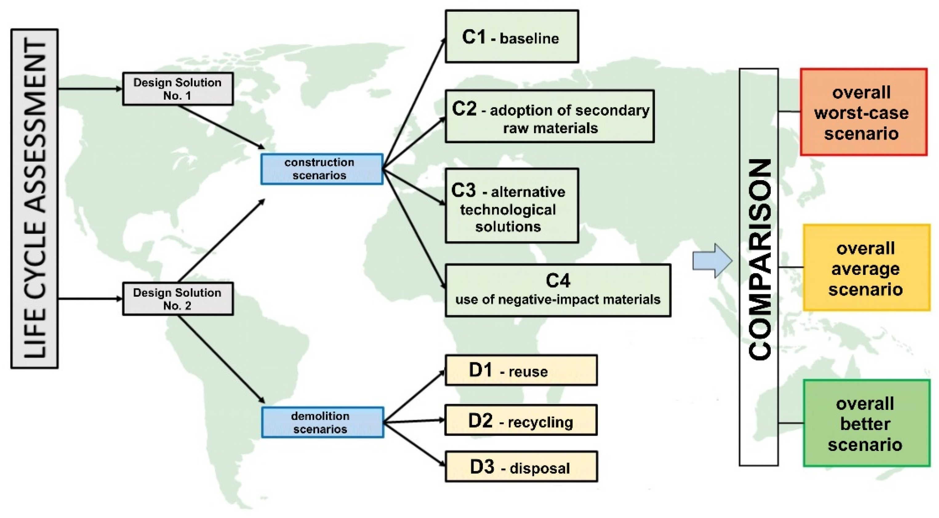
For the purpose of EC calculation, the building was decomposed into the main technological units: structure, intermediate floor and roof. The Construction phase, referred to in both design solutions (1-2), consists of 4 possible scenarios: Scenario C1 (starting situation-baseline); Scenario C2 (adoption of secondary raw materials); Scenario C3 (alternative technological solutions); Scenario C4 (reduction attributable to chemical properties of the material and technological solutions adopted). Scenario C1 (starting situation - baseline): In this phase, there is an analysis of the entire project, starting from its characteristics and critical issues. EC factors related to the use of virgin materials are evaluated. Scenario C2 (adoption of secondary raw materials): so-called secondary raw materials are adopted, where possible, consisting of scrap from the processing of raw materials, or materials derived from waste recovery and recycling. Such recycled products have a significantly lower EC factor than virgin raw materials. Scenario C3 (alternative technological solutions): a further reduction in EC factor is achievable through the use of “dry” technologies, compared to traditional “wet” methodologies. Scenario C4 (reduction in the amount of EC through the use of negative-impact materials): due to their physicochemical properties, wood products and derivatives are likened to true carbon incubators (carbon capture storage); LCI databases attribute negative EC factors to them.

3.3. Demolition Scenarios

For design solution #2, invasive demolition works are envisaged. The possible demolition scenarios (dependent on the final destination of the waste materials), are Reuse, Recycling, Landfill Disposal.

Scenario D1—Reuse

Italian (minimum environmental criteria) and EU (LEED, LEVELs, etc.) regulations require that, in renovation, maintenance and demolition operations, at least 70% by weight of the non-hazardous waste generated during the demolition and removal of buildings must be sent to operations of preparation for reuse, recovery or recycling. Thus, 30 percent will refer to the amount of CO2e inherent in materials destined for landfill, while for the remainder, 70 percent, where possible “as-is” reuse will take place (possibly on the construction site itself), also omitting transportation.

Scenario D2—Recycling

Recycling of building materials is a more sustainable alternative to landfilling. Compared to the ‘reuse’ scenario, recycling of materials, although it diverts them from the landfill, nevertheless involves processing that commits energy resources, relative to the treatment and processing of the decommissioned materials. The prevailing materials, reinforced concrete and bricks, do not have a predisposition, at the end of their lives, toward reuse, predominantly envisaging recovery in the form of recycling or disposal. The model related to the calculation of CO2e emissions, for materials destined for recycling, involves the following parameters: weight of material │type of treatment │type of machinery │hourly power of machinery │hourly amount of treatment │total hours of treatment │total energy required │incorporated carbon efficiency (EC) │total value of incorporated carbon.
The emission factor varies according to the power supply of the machinery used for demolition; CO2e is then calculated for transporting the waste, to the appropriate treatment sites, considering the destinations closest to the site: these are calculated based on the assumed number of trips (according to the maximum volume that can be transported by the vehicle), the kilometres travelled (distance of the site to the recovery site), and the average emission factor of the vehicles.

Scenario D3—Disposal

For the management of construction materials produced by the various activities carried out at the construction site, the Italian Ministerial Decree No. 186/2006, concerning the management of non-hazardous waste, must be taken as a regulatory reference. For all materials, resulting from demolition, a list of them will be made, with their weight in kilograms. The coefficient of EC considered is that corresponding to the production phase (from cradle to gate), related to modules A1, A2, A3, assuming, as the most negative scenario (baseline), total disposal in landfills. A rate related to transport is then added, i.e., the kilograms of CO2e generated on the way from the construction site to the appropriate landfill. Based on the maximum volume that can be transported by the vehicle, the emissions due to transport are calculated, taking into account: number of trips; kilometers travelled (yard landfill distance); average emission of heavy vehicles (668g/km).

3.4. Methodological Approach

The output target is to exceed the 55% threshold (in terms of CO2e emission reduction), compared to a baseline scenario. The two project assumptions (of which the second one also includes a demolition phase) are analyzed separately, so that the worst scenarios (C1+D3), the intermediate scenarios that do not allow the European threshold to be exceeded, and finally the best scenarios (C4+D1) that should allow, as an expected result, the pursuit of the set objectives.
Depending on the various scenarios, project or demolition, the various contributions of embodied CO2e are taken into account: Materials; Machinery and equipment; Transportation; Treated materials, with recycling/recovery process. The methodological equation is:
Preprints 102547 i001

4. Case Study: Refurbishment and Restyling of a Social Housing Complex in Southern Italy

4.1. Description of the Case Study

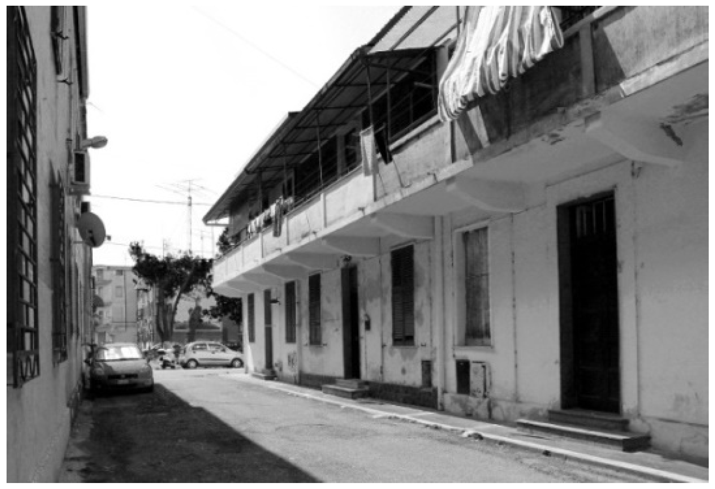
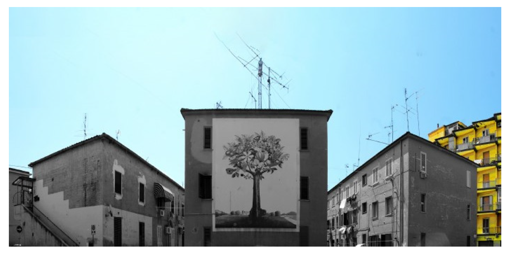
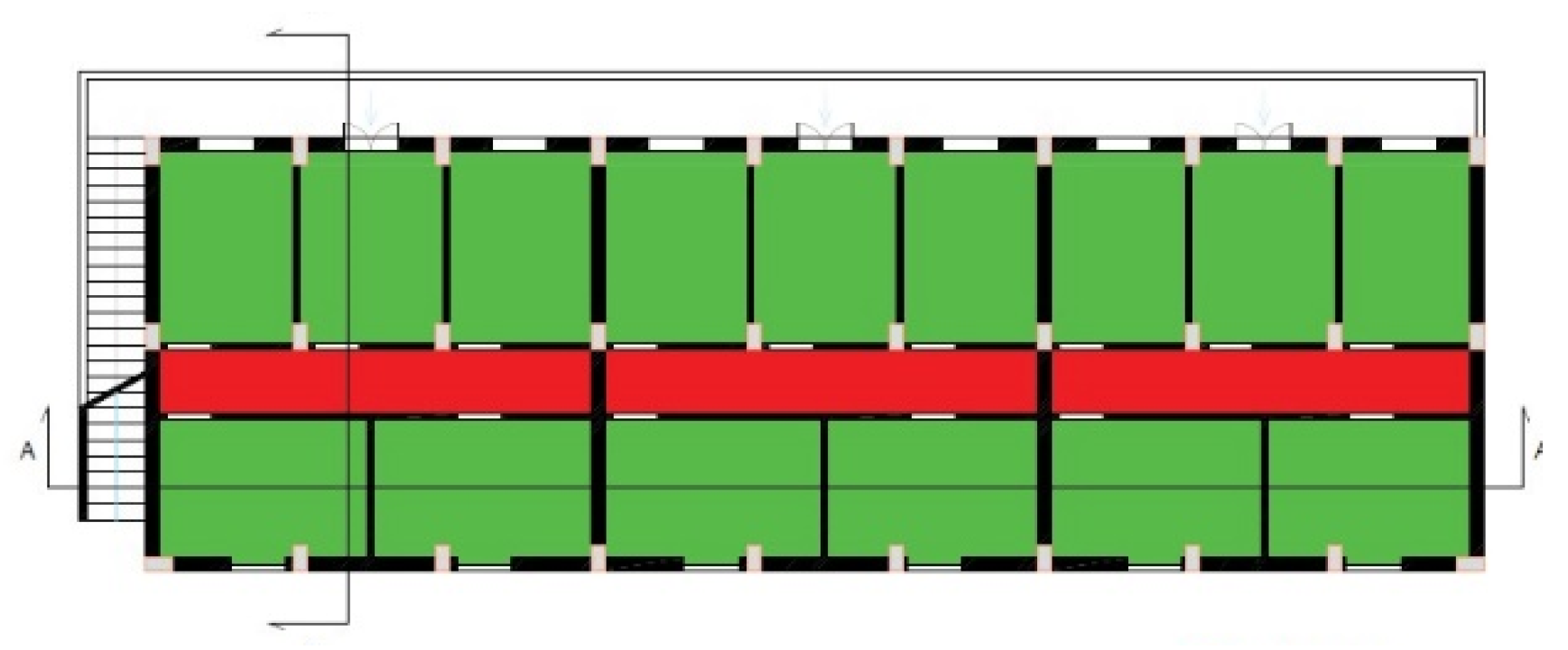
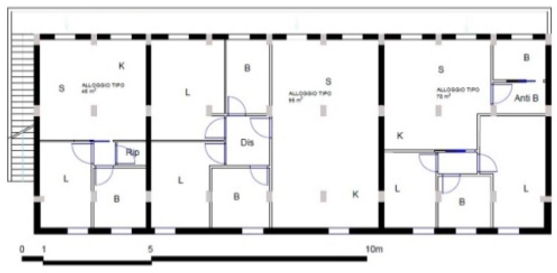
The output target is to exceed the 55% threshold (in terms of CO2e emission reduction), compared to a baseline scenario. The two project assumptions (of which the second one also The methodology (Figure 6) explained in the previous section was applied to two design ideas of energy efficiency, functional adaptation and facade restyling, inherent in an ideal renovation project, in the “Le Minime” neighborhood in Battipaglia (near Salerno, at Southern Italy), a typical example of social housing from the 1940s (Figure 7, Figure 8 and Figure 9). Initially, it arose in the suburbs, then incorporated by the growth of the city. The regular-shaped layout of the neighborhood responds to the logic of post-war housing, based on rigid subdivision. Today, this housing complex has been involved in some unfavorable dynamics, which have aggravated the situation of discomfort, such as the low turnover of resident inhabitants, to which has been added the settlement of weak segments of the population, concentrating them in these places, and a general process of aging of the resident population. The built-up area is in a situation of total abandonment, with a generalized degraded condition. In numerous places there is detachment of plaster, generalized material degradation, with obvious signs of “zero intervention.”

4.2. Design Hypotheses

For the purpose of the research, two design hypotheses were developed: one less invasive (scenario 1), another more invasive (scenario 2). The building, taken as a reference for the design simulation, is on two levels, each of which houses 3 apartments of about 50m2. The possible destinations and interventions can be multiple, as the neighborhood needs a good intervention to recover the built-up area, as well as a recovery of sociality and its diversification. One of the design constraints, leave unchanged the gallery typology, a typological feature that connotes the housing complex today. Interstorey heights are also maintained, and super elevation is planned in both scenarios. Demolitions are planned, related to the entirety of the interior infill wall faces, as well as partially on the envelope. Both interventions have similar characteristics, such as the use of steel for the integrated parts, due to the flexibility, lightness and strength of the material.

4.3. Design Solution No. 1: Construction

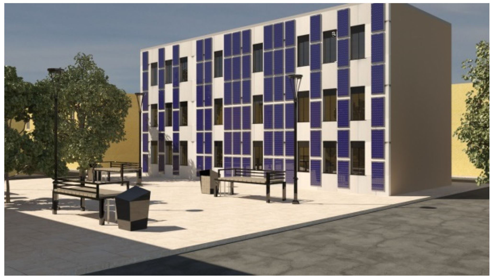
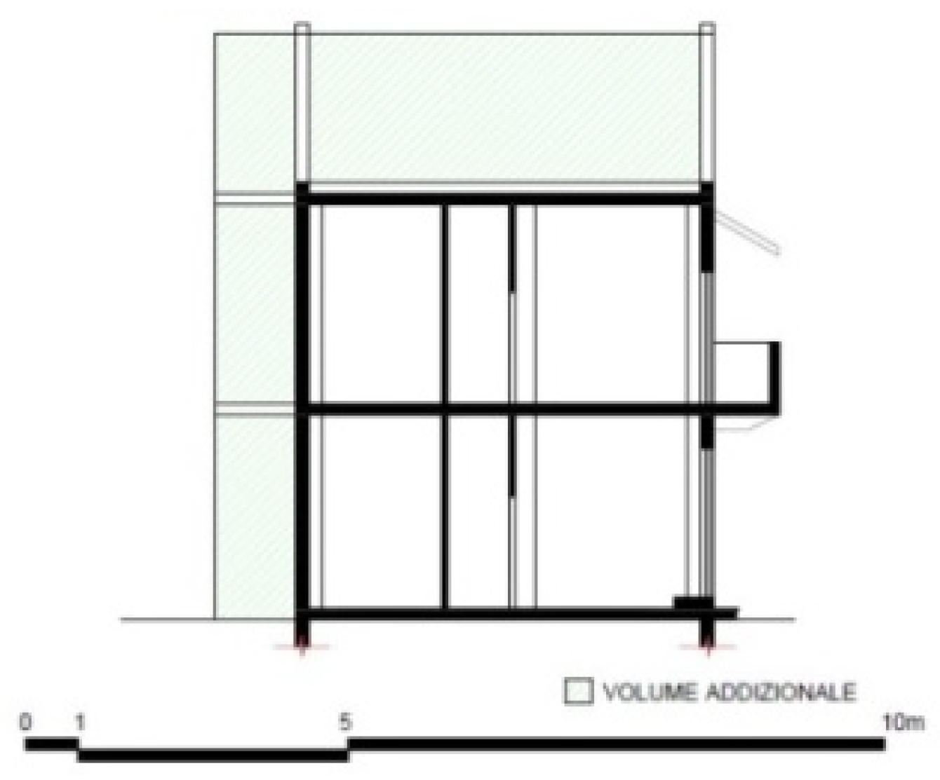
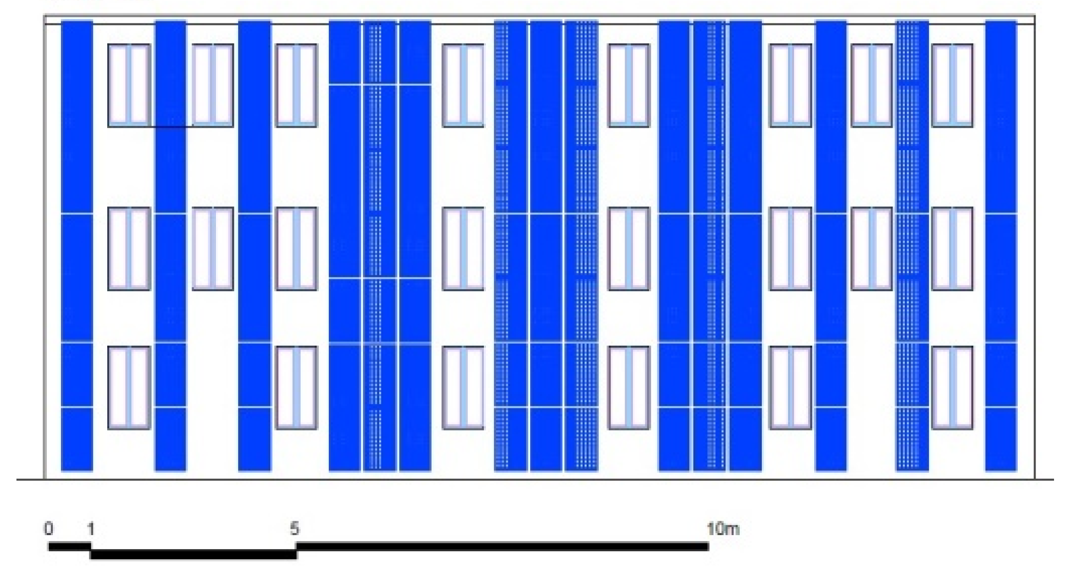
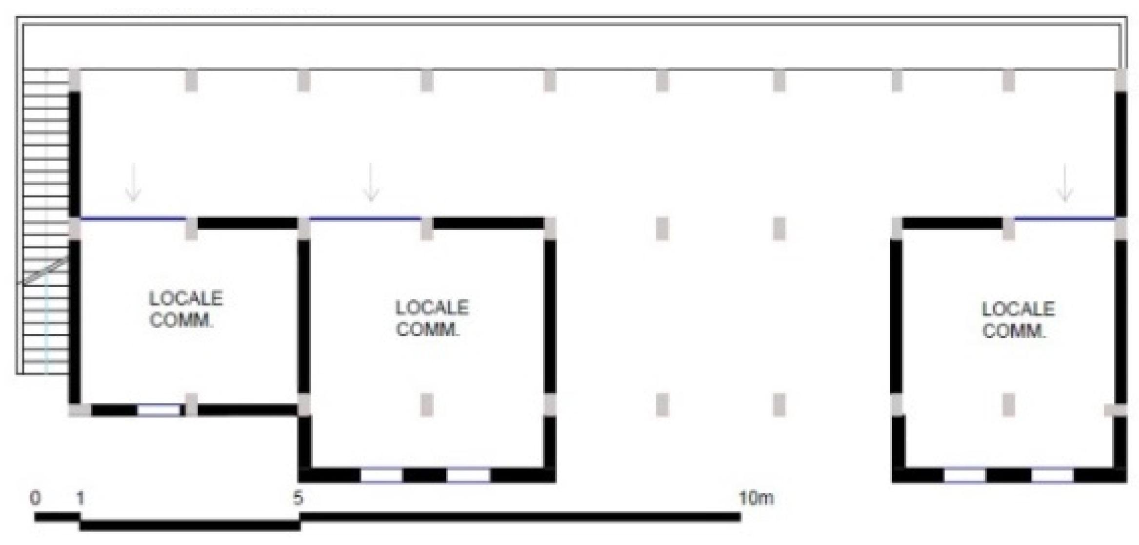
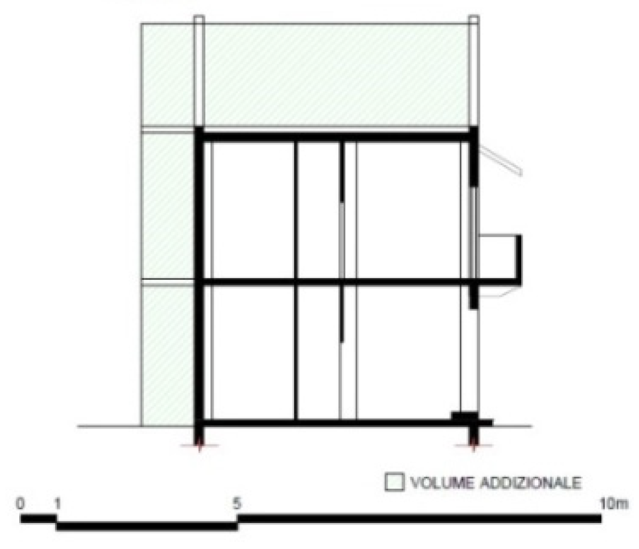
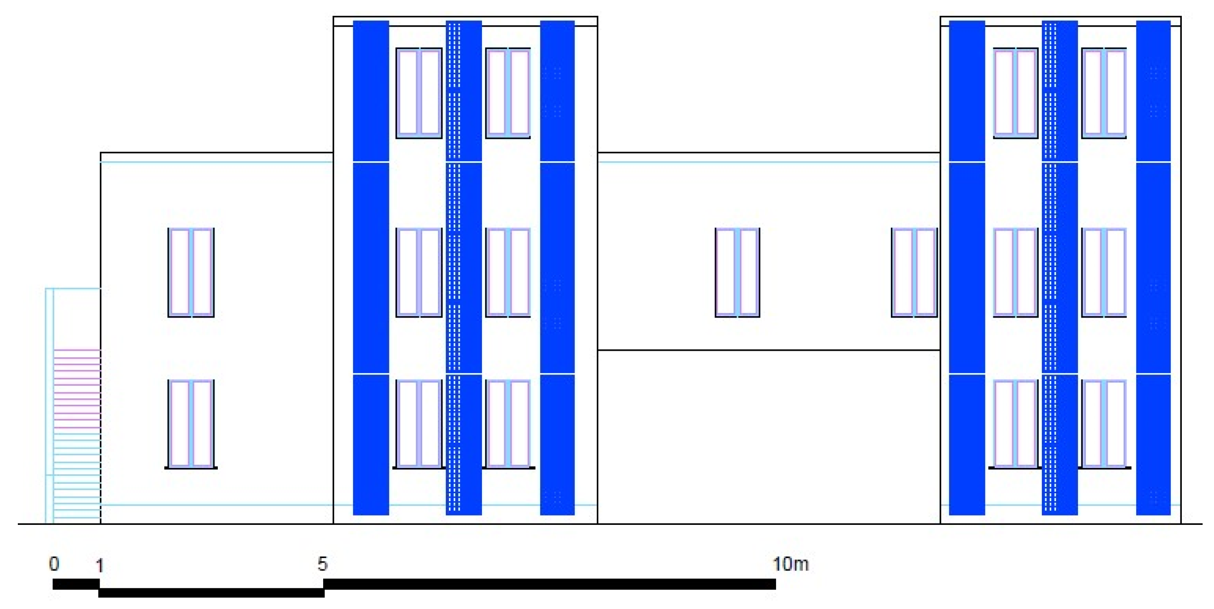
The first design idea (Figure 10, Figure 11, Figure 12 and Figure 19) is based precisely on the conservation approach, in which the basic idea of the adopted methodology is encapsulated. Importance is given to what is the settlement context, of a gallery type, preserving it and intervening minimally on the envelope. The use will remain predominantly residential, where, however, space will be given to some commercial establishments to diversify and intensify the categories of new users, providing new services to citizens. The current layout is maintained and an extension towards Renaissance Square of 1.5m is planned, as well as a 3m elevation for the entire building body, this in order to meet the vital need for larger spaces, and at the same time be able to allow thus a diversification of the same. The additional space turns out to be essential and useful for everyday life.
The design hypothesis ‘1’ includes the ‘addition’ mode of extension on the roof and facade.
-
The addition structure on the south front is steel, consisting of HEB180 columns, edge beams with IPE330 profiles, interior beams with IPE220 profiles, and IPE120 secondary beams. IPE 330 profiles were retained for the central part.
-
The external envelope, which forms the facade on the additional body, consists of photovoltaic panels on the elevation, alternating with appropriate openings. A 15cm-thick rock wool insulation layer is provided, incorporated within the HEB180 load-bearing metal profile, a 10cm air gap with modular breaks of 100x50mm steel box profiles such that a 12.5cm-thick fiber cement slab can be attached, followed by an exterior finishing layer. To the latter are doweled 50x50mm supports essential for fixing the photovoltaic panels on the facade.
-
The intermediate slab has steel structure IPE 330 and IPE 220, secondary profiles IPE220, is structured, proceeding towards each other in the slab stratigraphy, by 1.5mm thick corrugated metal sheet, structural screed with 12.5cm electro welded mesh, 10cm rock wool insulation layer, 5cm bedding screed and 1.5cm terracotta flooring. At the soffit, a lightweight metal structure for gypsum-fiber panelling ceiling.
-
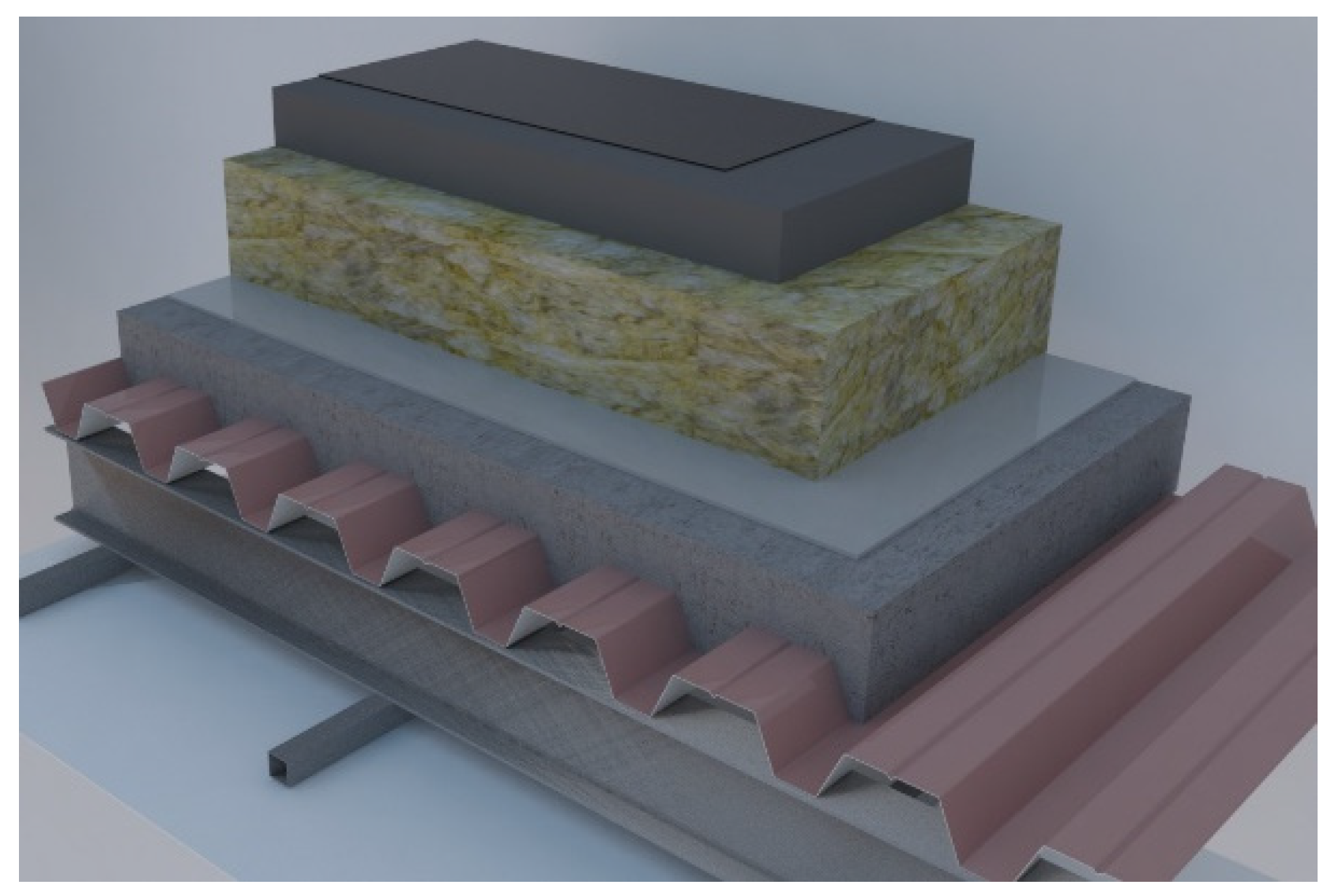
The roofing has dry stratigraphy, with steel structure, IPE330 and IPE220 profiles, IPE220 secondary profiles, on which 1.5mm corrugated metal sheet rests, followed by screed with 12.5cm electro welded mesh, a 0.5mm PVC waterproofing sheet, a 16cm rock wool layer, EPS layer, and finally to close a 3mm waterproofing sheathing. As a finish on the soffit there is a light metal structure for false ceiling in gypsum-fiber panelling (Figure 13).

4.4. Design Solution No. 2: Demolition + Construction

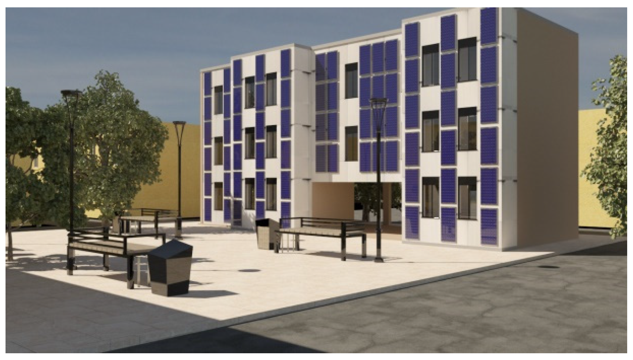
Design hypothesis No. 2 (Figure 14, Figure 15, Figure 16 and Figure 20) involves an invasive approach, with major demolitions, in order to also achieve a restyling result for the complex. This solution, like the first one, also envisages a 1.5m extension towards Renaissance Square, but in this scenario the addition is not uniform, but variously displaced along the original building body. It is planned, also in this scenario, a 3m elevation, for some parts of the building body, in order to meet the need for larger spaces, and at the same time to be able to allow a diversification of them. The emptying of the ground floor will allow an urban integration of the complex, creating a connection between Risorgimento Square and Garibaldi Street. On the elevation of Via Garibaldi, an emptying of half of the entire ground floor is generated, such as to give the building a pedestrian portico, serving the businesses present on the ground floor. All this promotes places of aggregation and a social diversification for the entire neighbourhood. The demolition part, moreover, will affect all the interior infill, so that new larger residential spaces can be created that also allow for diversification of the resident population. The exterior envelope will be demolished at the 1.5m exterior extensions, so that the interior spaces can be expanded and made more liveable. The building body consists of ground floor and second floor. On the ground floor, in this scenario, a large part of the ground floor is planned to be cleared, so as to generate a connection with the adjacent square. The additional body, with a steel structure, is not continuous on the facade, but follows an alternation of solids and voids, leaving part of the existing envelope in evidence. The facade is integrated with photovoltaic panels (BIPV). The technological construction features, for solution No. 2, are the same as those described for solution No. 1.

5. Application to Case Study

5.1. Design Solution No. 1

An inventory of materials is made for the considered building body and its weight in kilograms is calculated for each material.

5.1.1. Scenario C1—Starting Situation (Baseline)

This scenario is translated in terms of the amount of embodied carbon by associating the “coefficient of embodied carbon primary” contained in the “ICE database” with each material.

5.1.2. Scenario C2—Adoption of Secondary Raw Materials

Also in this scenario, the materials in the project are associated with the coefficient of embodied carbon, however, the coefficient to be considered in the database is the “coefficient of embodied carbon secondary.” The ‘inventory specifies that during recycling, many facilities have different recycling rates and processes, which is precisely why in the latest version of the database, “V3.0,” these coefficients were abolished and kept only those where the recycling process was almost unchanged. For this reason, the coefficient is applied only to certain materials, namely steel. For steel beams, a recycling rate of 98 percent is considered, while for corrugated sheets, concrete casting must be taken into account and thus a recycling rate of 70 percent.

5.1.3. Scenario C3—Alternative Technological Solutions

The technological interventions carried out are:
-
Replacement of insulation material with one with low CO2e emissions; rock wool is replaced with a wood fiber panel.
-
Replacement of inter-floor floor construction technology; the present stratigraphy (floor with a “wet” system) is replaced with a “dry” technology (Figure 17).

5.2. Design Solution No. 2

5.2.1. Demolition

The second, more invasive project involves demolition with partial emptying of the ground floor and demolition of part of the south side facade. A list of the materials to be demolished is made and their weight in kilograms is calculated, before proceeding to quantify the CO2e in the various scenarios.

5.2.2. Scenario D1—Reuse

The reuse scenario involves using the building element as-is by providing for hydro pulping, which is a high-pressure jet that succeeds in removing impurities. It is assumed that, where possible, materials are reused on-site. Bricks can be reused for paving. Therefore, emissions from transportation are zero. The walls are assumed to be demolished with a grapple excavator, and debris handling is done with a crawler excavator with bucket.

5.2.3. Scenario D2—Recycling

The items we have considered are all recyclable. To make them so they need treatment according to their future use. The treatment needed, is crushing and screening, by doing so the plasters can be used for subgrade screeds and fills. The bricks can be repurposed as a second raw material or as subgrade. The mortar can be reused for fills. The destination plant was considered to be at a distance of 4.5km from the construction site and has the possibility of recycling/recovery of inorganic substances.

5.2.4. Scenario D3—Disposal

In this scenario, the weight of individual building elements and materials is associated with the internal carbon coefficient selected from the “inventory of carbon and energy.”
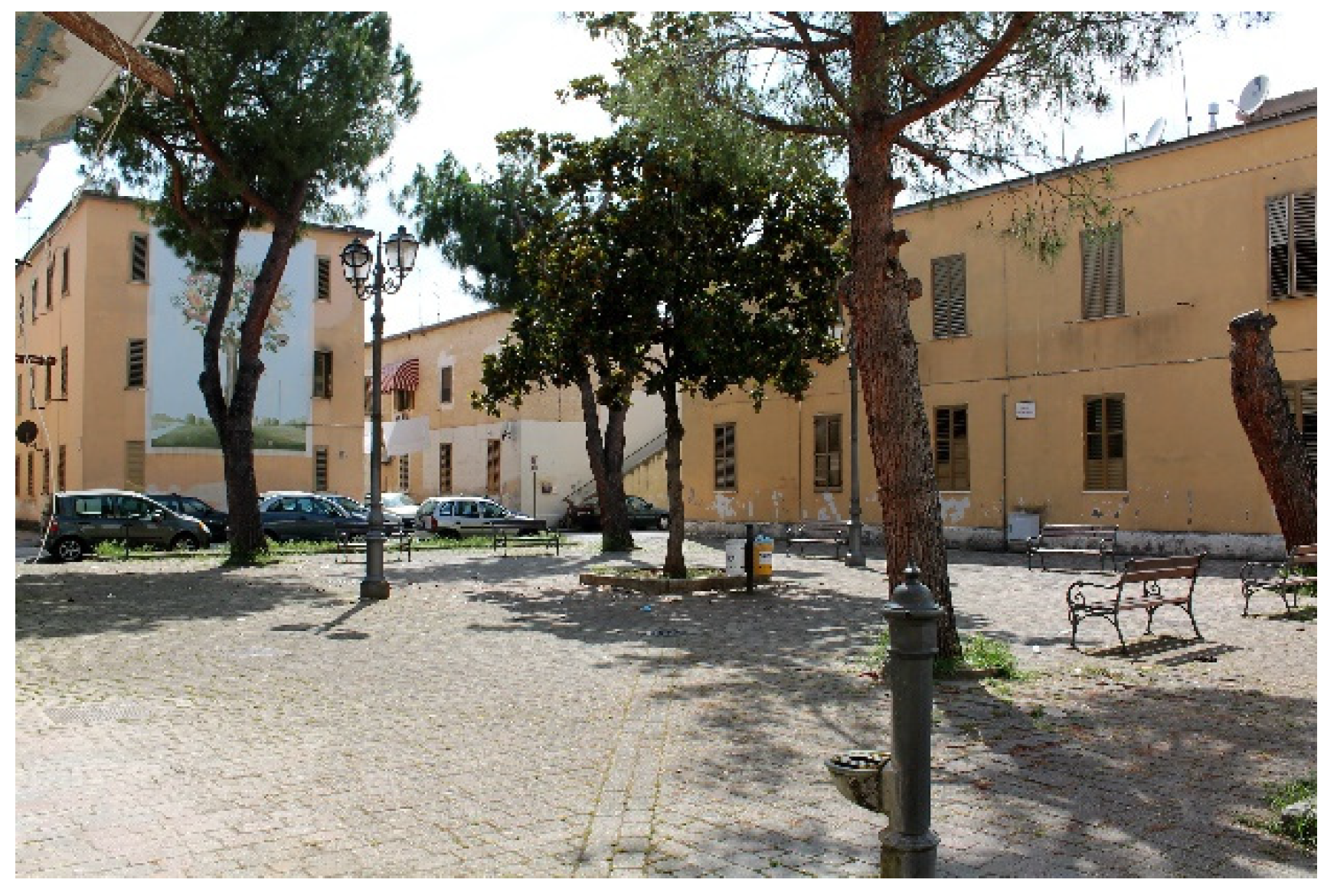
Figure 18. Actual photo of the building under study.
Preprints 102547 g018
Figure 19. Design Solution No. 1.
Preprints 102547 g019
Figure 20. Design Solution No. 2.
Preprints 102547 g020

6. Results and Discussions

6.1. Results of Design Solution No.1
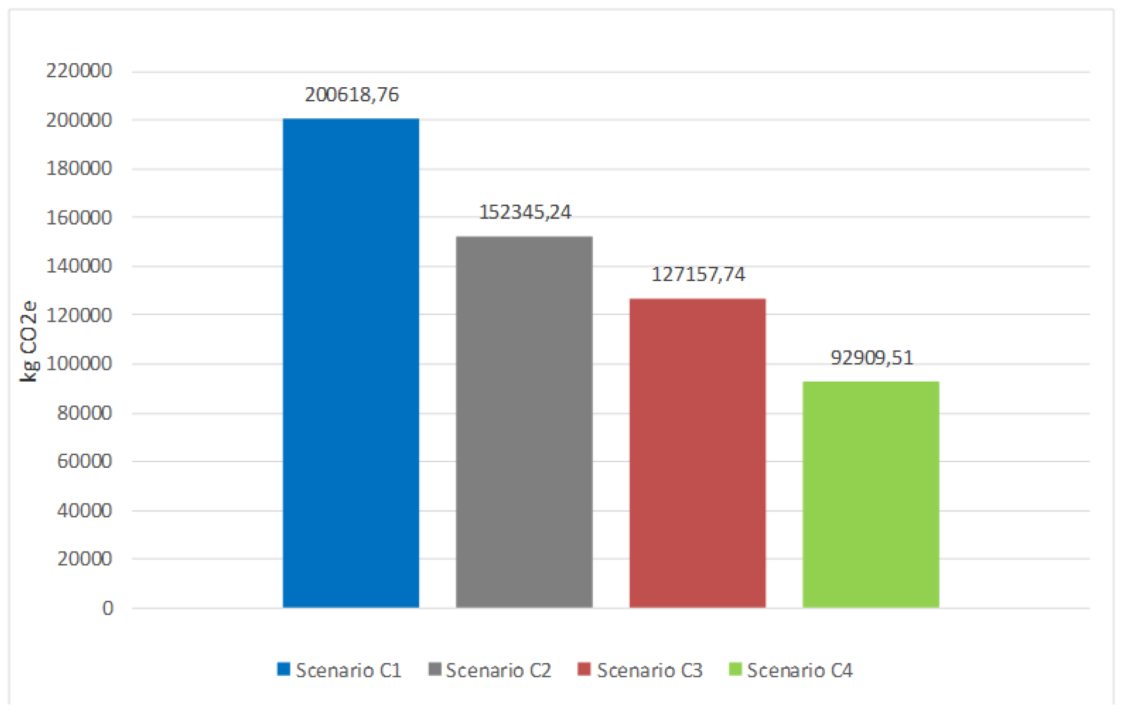
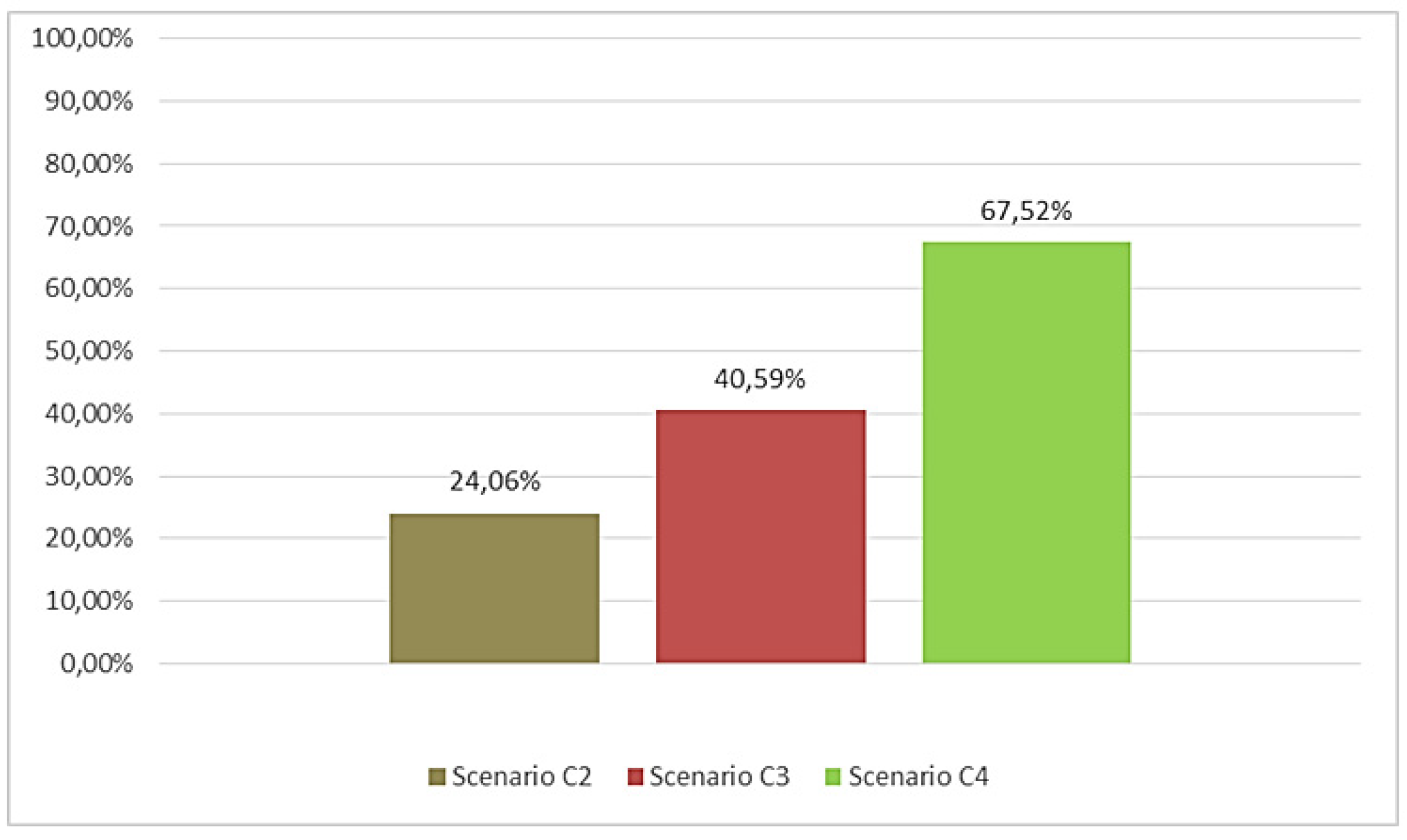
The graph in Figure 21 shows the results of the methodology applied to design solution #1, where we only have the design phase. Scenario C2, is the one with the very first carbon reduction, due to the use of recycled materials. These have lower embodied carbon because, mainly, the carbon rate due to raw material sourcing is lost (LCA module A1). Scenario C3, further emission reduction was still sought, so that alternative technological solutions were considered, preferring “dry” technologies (x-lam panels, cork and concrete-wood), rather than “wet” (rock wool, concrete, trapezoidal sheet metal). Vegetable fiber materials allow for significant CO2 reduction, however, given the presence of steel structures, which significantly affect the final result, it is still not found to be satisfactory for achieving the European target. In scenario C4, aspects intrinsically related to plant materials are considered, in particular, their carbon storage property.
Figure 21. Embodied Carbon factor for Design Solution No. 1.
Preprints 102547 g021
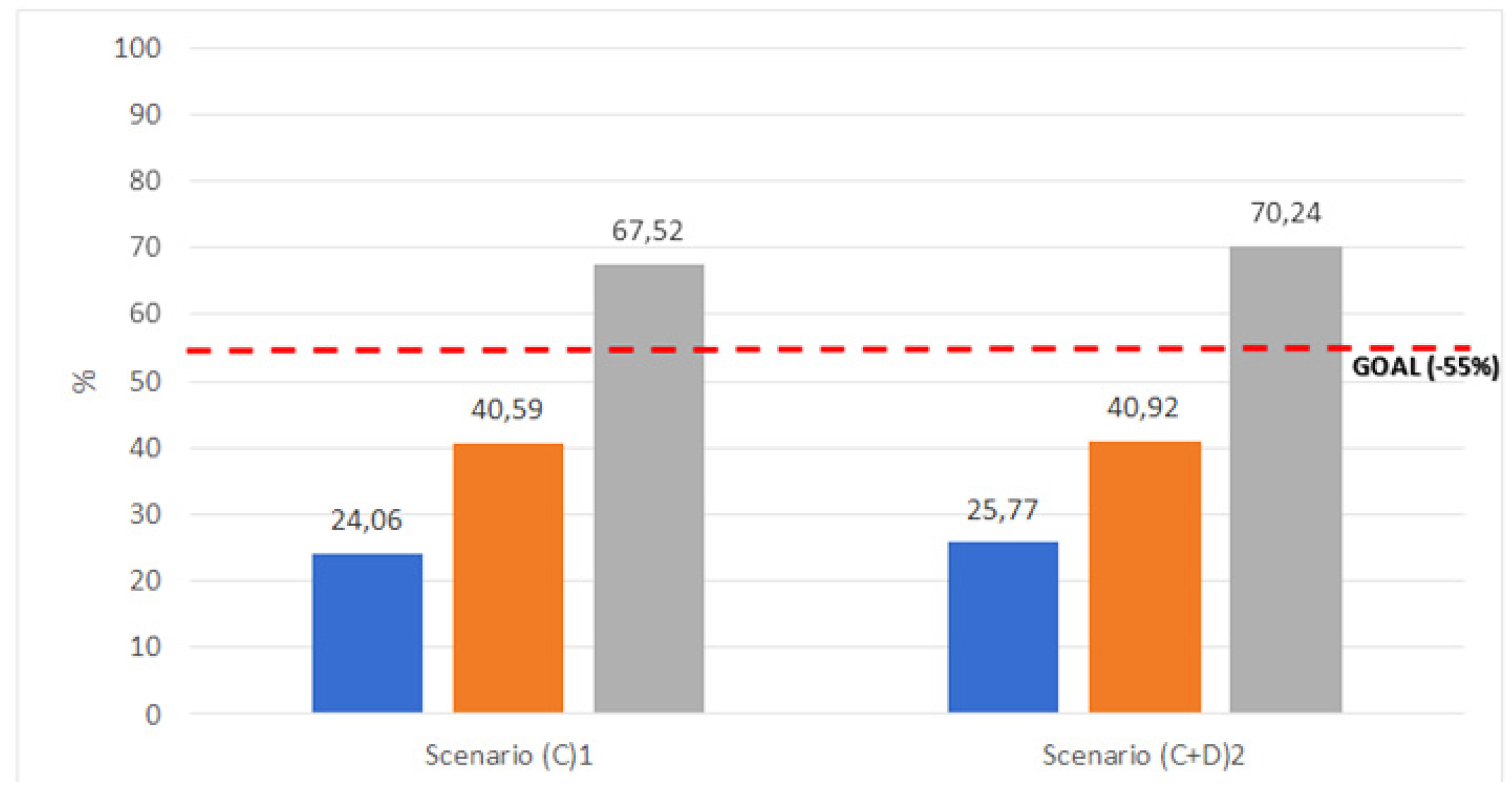
This allows us to have negative embedded carbon coefficients, since by using such materials, we are removing carbon from the environment. This allows us to achieve further significant carbon reductions, approaching 70 percent in the present case. Of course, this is also closely related to the volume of material used, which allows the parameter to grow as volumes increase. The following graph highlights the difference expressed in kg CO2e between the various design scenarios. The graph in Figure 20 highlights the percentage reduction in carbon emissions incorporated in the different project phases, with the target of -55%. The graph in Figure 22 shows the ideal scenario that exceeds the initial target: Scenario C4 achieves a reduction in CO2e emissions of 67.52%, compared to the baseline scenario.
Figure 22. Incidence of CO2e emission reduction (design solution No.1).
Preprints 102547 g022

6.2. Results of Design Solution No.2
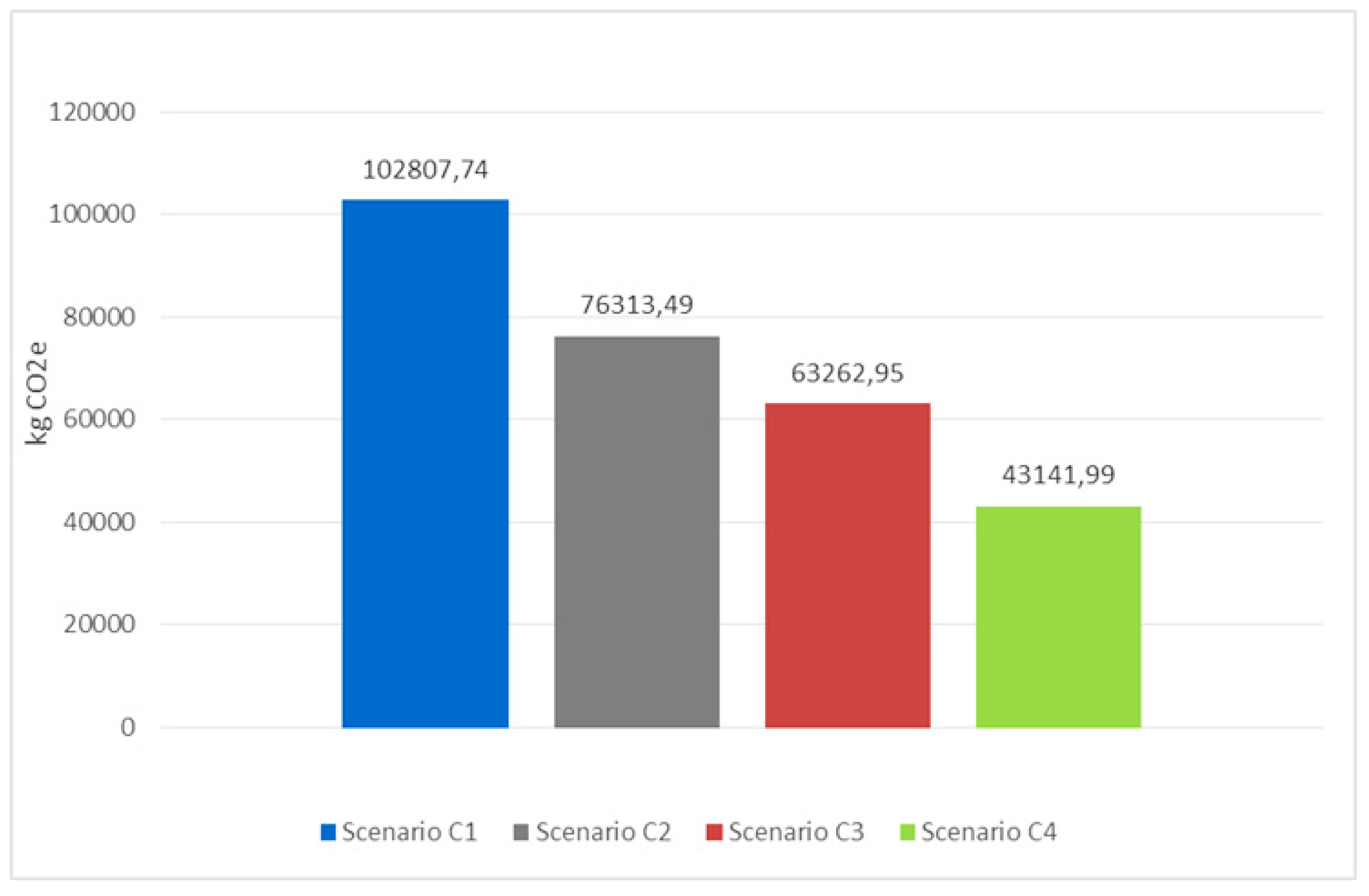
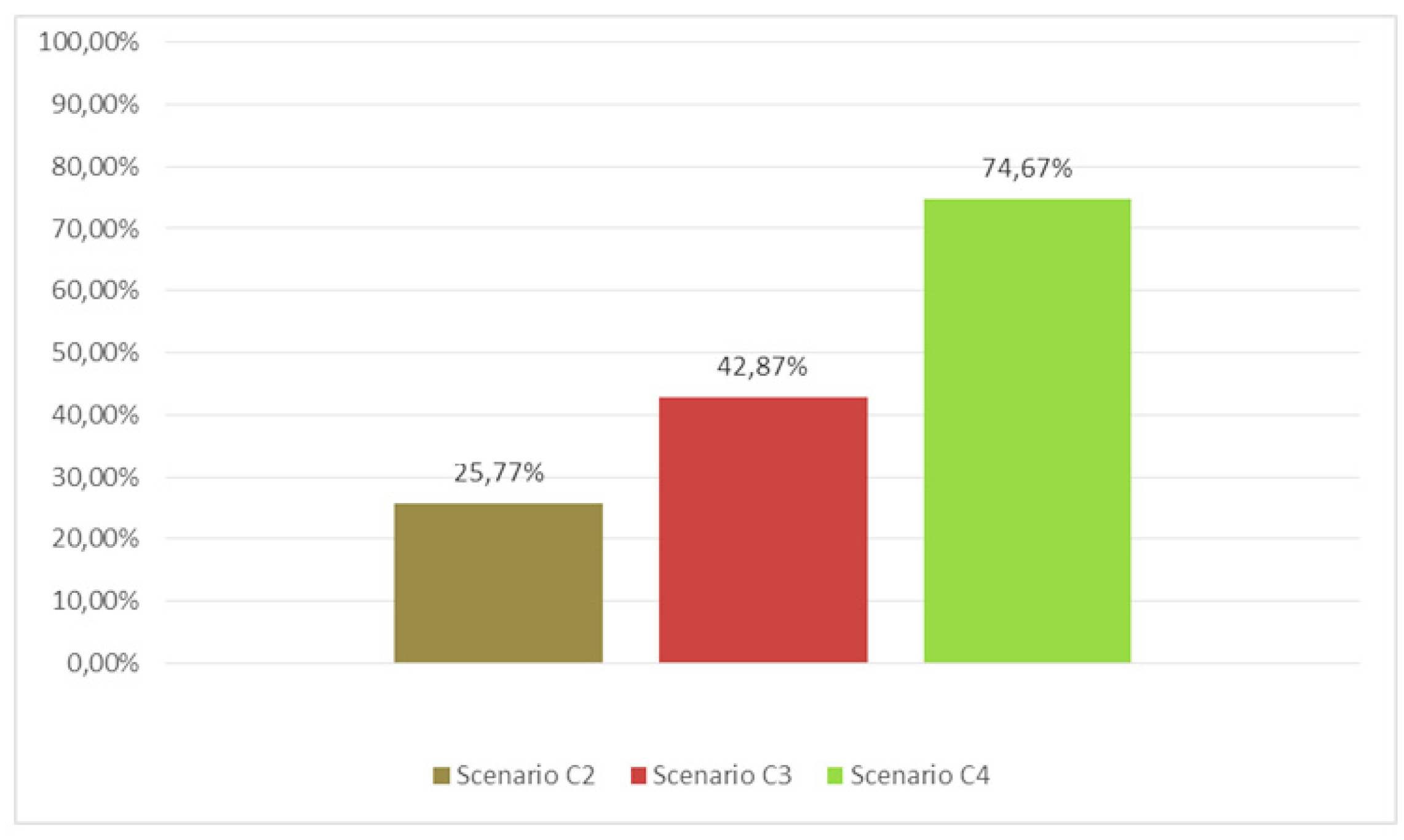
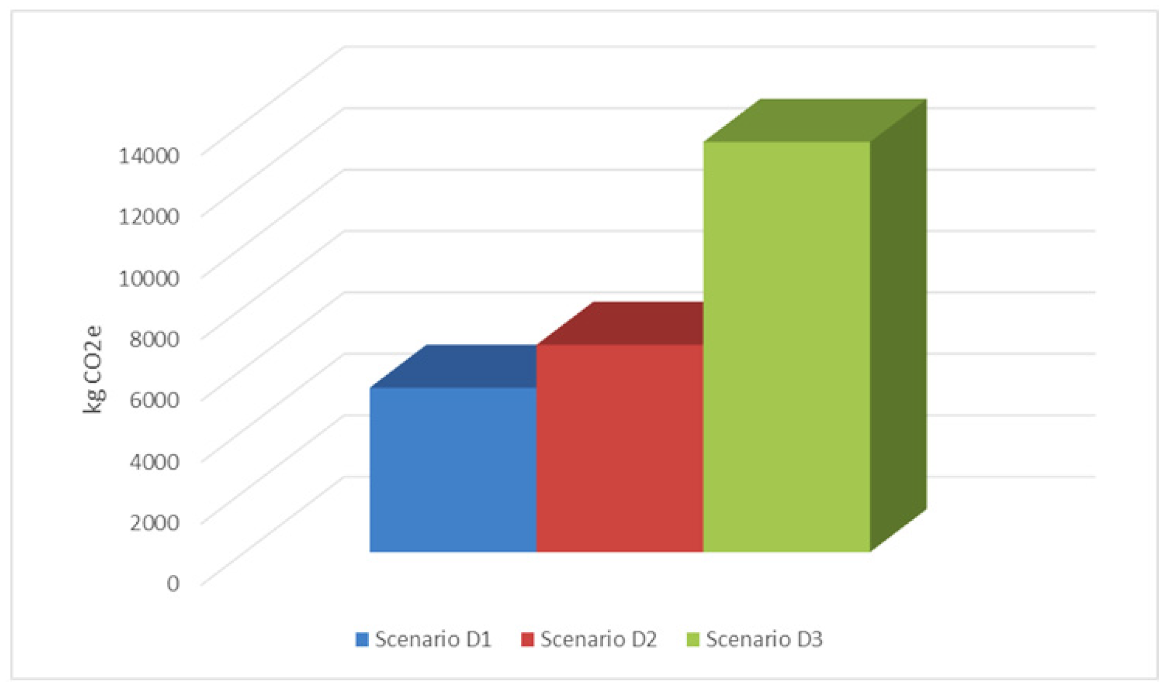
Analysing the project phase, it can be seen that the emissions have a range from 102807 kgCO2 for the C1 (baseline) scenario, to 43141 kgCO2e for the C4 scenario. Again we go on to analyse the different scenarios. For scenario C2 the percentage reduction is broadly below 55%. The same is repeated for scenarios C3 and C4, where again the replacement of the “wet” slab (rock wool, concrete, trapezoidal sheet metal) with a “dry” one (x-lam panels, cork and concrete-wood) has been planned. Scenario C4, as shown in Figure 24, allows for an exceedance of the threshold, mainly due to the carbon storage properties of the materials used for the inter-floor slab and partly in the roof structure. Scenario C4, as can also be seen in the following graph, thanks to the carbon storage properties, allows us to exceed the 55% threshold.
Figure 23. Embodied Carbon factor for Design Solution No. 2.
Preprints 102547 g023
Figure 24. Design Solution No. 2: Possible combinations of the construction and demolition scenarios.
Preprints 102547 g024
Already in scenario C3, the replacement of the intermediate floor slab took place, with “dry” technology, but this did not allow for an exceedance of the target, standing at 42.87%. Considering those aspects intrinsically related to plant materials, in particular, their carbon storage property, it was possible to reach the target in scenario C4, with a percentage reduction of 74.67%. Thus, the last scenario, presents itself as indispensable for exceeding the European goals, as well as points out to us that an extension of the intervention would succeed in leading us to climate neutrality by 2050, given the important percentage achievement of this approach.
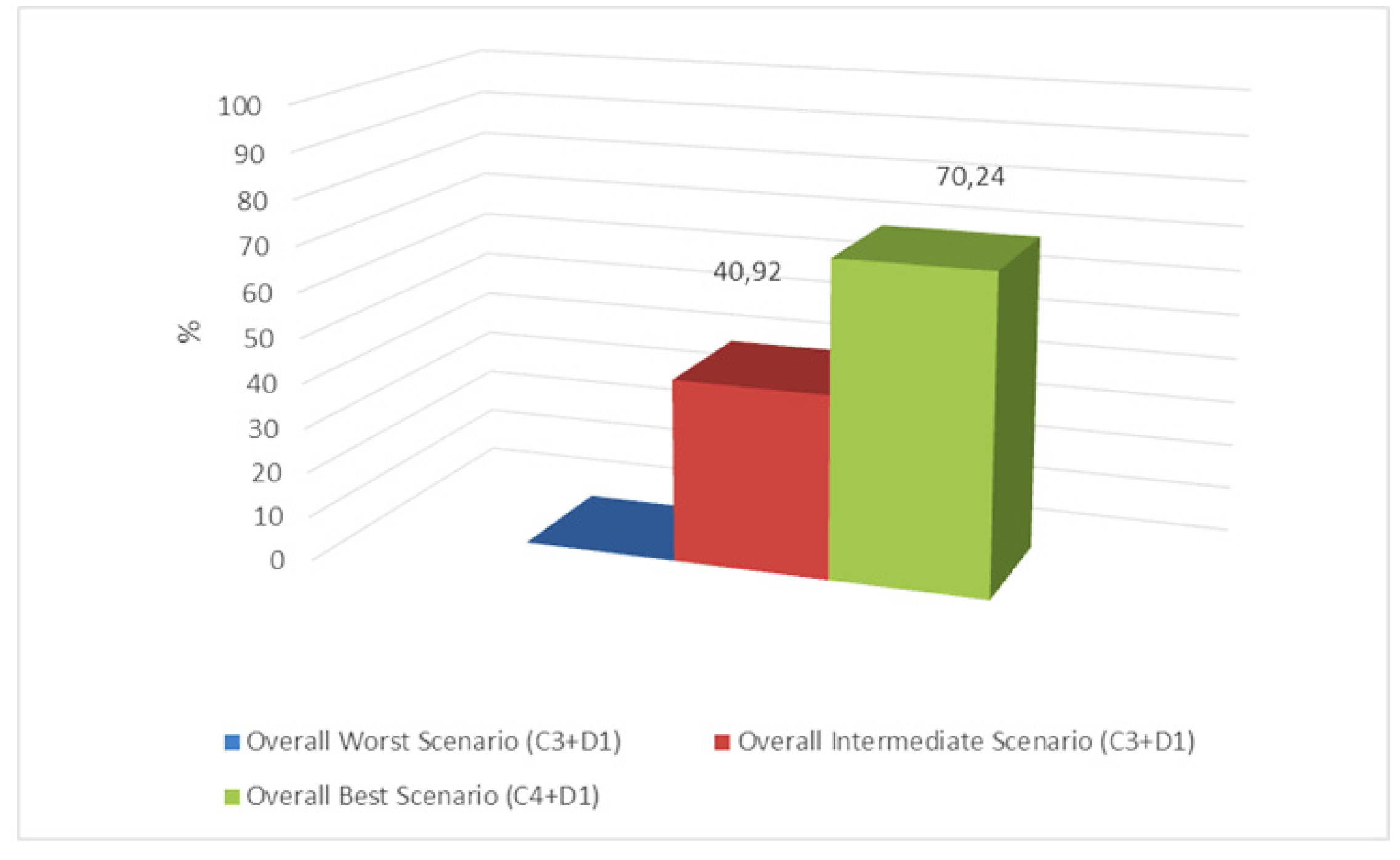
Relative to the design solutionen.2, the results of the demolition scenario are finally combined with the possible design scenarios: an “overall worst case scenario” (C1+D3) is thus identified, which involves the sum of the embodied kilograms of carbon from scenario C1 (baseline situation) and scenario D3 (landfill disposal); then an “overall intermediate scenario” (C3+D1); finally, the “overall best scenario” (C4+D1), which allows the predetermined threshold (-55% CO2e) to be exceeded, resulting from the combination of the C4 project scenario (reduction attributable to the chemical properties of the material and technological solutions adopted) with the D1 scenario (reuse/recycling). Analysis of the latter table shows how thoughtful design choices, both at the design and demolition stages, can lead to the achievement of rewarding goals. It is often thought that demolition is in any case more impactful than other more conservative scenarios. Instead, when checking the final percentages, in addition to achieving the European goals in the third combination, one can also see a slight increase in the percentage reduction in carbon by making appropriate choices at the design stage while providing for invasive demolition choices.
As can be seen from the graph in Figure 25, by making appropriate design choices, it is possible to intervene even more invasively from a demolition standpoint, and achieve even better results (not assumed at the outset) inherent in the reduction of embedded carbon.
Figure 25. Embodied carbon emissions related to the demolition phase (project no. 2).
Preprints 102547 g025
Figure 26. Design Solution No. 2: Possible combinations of scenarios.
Preprints 102547 g026
Figure 27. Comparison, in terms of percentage reduction of CO2e, between the design solutions: no.1 (construction) and no.2 (demolition+construction).
Preprints 102547 g027

7. Conclusions

The study aimed to demonstrate the possibility of achieving the European Union target (EU Regulation 1119/2021), of CO2e emission reduction of at least 55%, in the construction industry sector. Two design solutions were developed, including a less invasive one and a more invasive one that also includes a demolition portion. For each of these solutions, possible environmental impact scenarios (in terms of CO2e emissions) were assumed for both the construction and demolition phases. The methodology was applied to two design hypotheses for the reconfiguration and rehabilitation of a building in the Social Housing complex in the city of Battipaglia (near Salerno, at Southern Italy). The results showed that design hypothesis 2, which is more invasive, has a better environmental impact than design solution 1, which is more conservative. The results show a greater sustainability of “dry” systems compared to “wet” systems, allowing the former, a more sustainable end-of-life management phase, also recalled in the disassembly plan provided in the Italian Minimum Environmental Criteria. In addition, the use of sustainable materials has enabled a significant reduction in embodied carbon; the technological system made of wood and its derivatives also provides an effective response in the decarbonisation process. The results showed that it is possible to achieve a greater reduction in environmental impact while adopting a reconfiguration, rehabilitation and restyling intervention of Social Housing.

References

  1. Directive (EU) 2023/1791 of the European Parliament and of the Council of 13 September 2023 on Energy Efficiency and Amending Regulation (EU) 2023/955. Available online: https://eur-lex.europa.eu/legal-content/EN/TXT/?uri=OJ%3AJOL_2023_231_R_0001&qid=1695186598766.
  2. Alessi, A. Riguadagnare lo Spazio, in Materialegno 4, Lo Spazio Ritrovato, Milano, 2011.
  3. Daglio, L. Nuovo Suolo: Riuso e Recupero Delle Superfici in Quota Degli Edifici in, “Costruire nel Costruito. Architettura a Volume Zero”, collana Architettura e Città. Argomenti di Architettura, Milano, 2012. Available online: https://re.public.polimi.it/handle/11311/692634#.WE7i-rLhCR0.
  4. Reale, L. Densità, Città, Residenza. Tecniche di Densificazione e Strategie Anti-Sprawl. Gangemi Editore, Roma, 2008.
  5. Ferrante, A.; Cattani, E.; Bartolini, N.; Semprini, G. La Riqualificazione Energetica e Architettonica del Patrimonio Edilizio Recente, in Ricerche e Progetti per il Territorio, la Città e L’architettura, no. 5 Dicembre, 2012.
  6. Spagnolo, R. La Rigenerazione Urbana Come Problema di Ri-Composizione Architettonica, in Marta Calzolaretti, Domizia Mandolesi (a cura di), Rigenerare Tor Bella Monaca, Macerata, 2014; p. 83.
  7. Calzolaretti, M. Perché Tor Bella Monaca. Il Programma di Ricerca, in Marta Calzolaretti, Domizia Mandolesi (a cura di), Rigenerare Tor Bella Monaca, Macerata, 2014; p. 17.
  8. Sicignano, E. La Demolizione Quale Esorcismo del Male Sociale: Il Caso delle Vele di Scampia a Napoli, in Rita Maria Borboni, Città&Criminalità, Pesaro, 2005; pp. 233–241.
  9. Valente, I. Consolidare e Ri-Misurare i Margini Urbani: Una Ricerca Progettuale per Tor Bella Monaca, in Marta Calzolaretti, Domizia Mandolesi (a cura di), Rigenerare Tor Bella Monaca, Macerata, 2014; p. 86.
  10. Valente, I. Consolidare e Ri-Misurare i Margini Urbani: Una Ricerca Progettuale per Tor Bella Monaca, in Marta Calzolaretti, Domizia Mandolesi (a cura di), Rigenerare Tor Bella Monaca, Macerata, 2010; p. 88.
  11. Portoghesi, P. In Materia n.44-45, Milano, 2012; pp. 35–39.
  12. Wien, Gasometer D, Wilhelm Holzbauer, Blick aus Einer Dachwohnung. 2001. Available online: https://www.alamy.com/wien-gasometer-d-wilhelm-holzbauer-2001-blick-aus-einer-dachwohnung-image221171876.html.
  13. Caruso, M.C.; Menna, C.; Asprone, D.; Prota, A. Methodology for Life-Cycle Sustainability Assessment of Building Structures. ACI Struct. J. 2017, 114, 323–336. [Google Scholar] [CrossRef]
  14. Embodied Carbon—The ICE Database. Available online: https://circularecology.com/embodied-carbon-footprint-database.html.
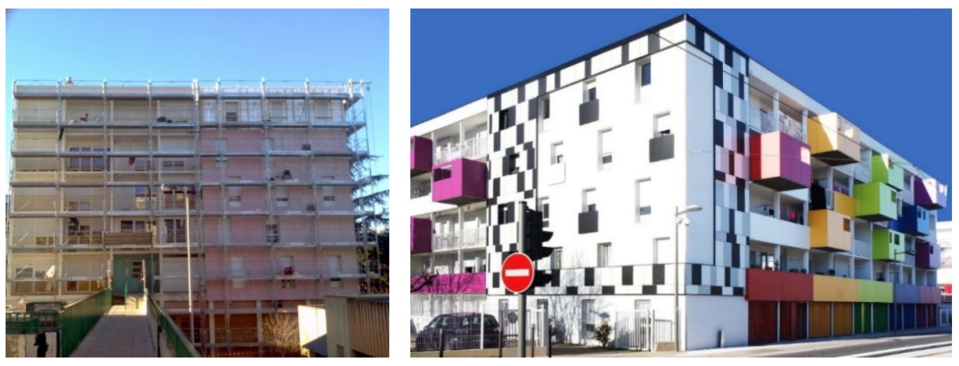
Figure 1. Transformation (additions, selective demolitions), Monpellier, redevelopment of social residential building.
Preprints 102547 g001
Figure 2. Transformation (selective demolition), Leinfelde residential building (source http://www.bryla.pl/bryla).
Preprints 102547 g002
Figure 6. Methodological framework.
Preprints 102547 g006
Figure 7. Photos of the current state.
Preprints 102547 g007
Figure 8. Photos of the current state.
Preprints 102547 g008
Figure 9. Floor plan of the building analysed.
Preprints 102547 g009
Figure 10. Design Solution No. 1.
Preprints 102547 g010
Figure 11. Design Solution No. 1.
Preprints 102547 g011
Figure 12. Design Solution No. 1.
Preprints 102547 g012
Figure 13. Technological stratification of the roof slab.
Preprints 102547 g013
Figure 14. Design Solution No. 2.
Preprints 102547 g014
Figure 15. Design Solution No. 2.
Preprints 102547 g015
Figure 16. Design Solution No. 2.
Preprints 102547 g016
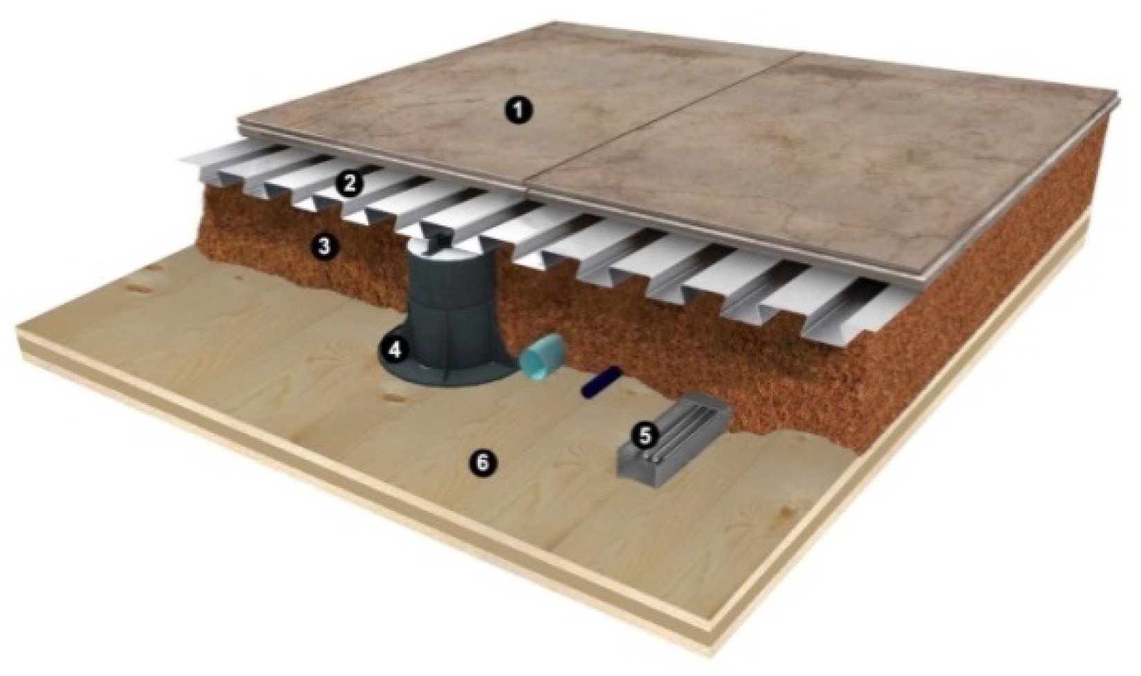
Figure 17. Inter-floor slab solution. From top to bottom: 1) 18 mm wood-cement panel, 2) 0.8 mm trapezoidal sheet metal, 3) cork granules, 4) plastic support, 5) implants, 6) 120 mm X-Lam panel.
Preprints 102547 g017
Disclaimer/Publisher’s Note: The statements, opinions and data contained in all publications are solely those of the individual author(s) and contributor(s) and not of MDPI and/or the editor(s). MDPI and/or the editor(s) disclaim responsibility for any injury to people or property resulting from any ideas, methods, instructions or products referred to in the content.
Copyright: This open access article is published under a Creative Commons CC BY 4.0 license, which permit the free download, distribution, and reuse, provided that the author and preprint are cited in any reuse.
Prerpints.org logo

Preprints.org is a free preprint server supported by MDPI in Basel, Switzerland.

Subscribe

© 2024 MDPI (Basel, Switzerland) unless otherwise stated