Preprint
Article

Stability Analysis and Dynamic Simulations for Gravity Gradient of a Large Rigid Space Structure

Altmetrics

Downloads

98

Views

35

Comments

0

This version is not peer-reviewed

Submitted:

29 March 2024

Posted:

29 March 2024

You are already at the latest version

Alerts
Abstract
The attitude dynamics and orbit dynamics of large rigid space structures are coupled with each other under gravity gradient, which may affect the stability of the large rigid space structures. In this paper, the gravity gradient stability of a large rigid space structure is studied under both small and large disturbances. Based on the rigid body dynamics and orbit dynamics, an accurate dynamic model without any linearization of the large rigid space structure is established via the natural coordinate formulation (NCF), which is able to describe the large overall motions of the structures. By using the generalized-α algorithm, the gravity gradient stability of the large rigid space structure is simulated and analyzed via various examples, including the influence of large disturbance angles, the positions at the stabilization and unstabilization regions. Finally, the relationship between spinning stability and gravity gradient stability is also investigated via a large spinning space structure.
Keywords: 
Subject: Engineering  -   Aerospace Engineering

1. Introduction

With the increasing demands of space missions and the rapid development of space technology, the requirements and prospects of large-scale space structures with a size of hundreds of meters or even kilometers are becoming more and more extensive [1-3]. For large space structures, due to their large sizes and masses, the gravity gradient torque is affected by the variation of their attitudes. At the same time, their attitudes and orbital dynamics are coupled with the gravity gradient [4]. As a result, it is of practical significance to study the influence of gravity gradient on the dynamics and stability of large space structures.
For different space mission requirements, researchers have proposed and developed various kinds of large space structures. For example, Freeland et al. [5] studied a 25-meter inflatable antenna for the ARISE (Advanced Radio Interferometry Between Space and Earth) space program. Meguro et al. [6] developed a cable net antenna composed of 14 basic module units with a diameter of 4.8 meters and applied it to ETS-VII satellite. The bridge relay satellite launched by China in 2018 is equipped with a self-developed 4.2-meter aperture cable net reflector antenna [7]. Li et al. [8] proposed a multi-rotation joint type solar power station, which has been the most representative power station scheme in China. Lu et al. [9] studied a nonlinear dynamic model of a tensioned space membrane antenna. Mankins [10] proposed the SPS-ALPHA (Solar Power Satellite by means of Arbitrarily Large Phased Array) and some other new concepts of solar power station. Fu et al. [11] proposed an external heat flux expansion formula for the heat design of solar power station. Seboldt et al. [12] put forward the concept of solar sail tower space solar power station. Tang et al. [13] studied the equivalent dynamic model of a large space telescope truss structure. Guo et al. [14] designed a kind of large space umbrella truss structure and studied its nonlinear dynamic characteristics. Due to their large-scale sizes and masses, the gravity gradient torque of large space structures may seriously affect their attitude stability and the success of their on-orbit missions. Therefore, it is necessary to carry out the stability analysis and corresponding simulations of large space structures under gravity gradient torque.
Many researchers have focused on the stability analysis for gravity gradient of large space structures under small disturbance angle. For example, Moran [15] studied the influence of the dynamics of the dumbbell-shaped satellite under the coupling of gravity attitude and orbit dynamics. Yu [16] used the Kryloff-Bogoliuboff method to analyze the long-term orbital dynamics of a small gravity gradient stabilized satellite under gravity attitude-orbit cooperation. Ashenberg [17] studied the gravity-attitude-orbit coupling problem of a finite number of mutually attractive celestial bodies, and derived the dynamic equation of the system. Wang et al. [18] studied the gravitational attitude-orbit coupling dynamic characteristics of a spacecraft with a special configuration flying around an asteroid. Wu et al. [19] studied gravity gradient stabilized satellite attitude tracking control via iterative learning control. Wei et al. [20] carried out an inflatable test of a space boom under the influence of gravity gradient. Hatten et al. [21] used the Lie–Deprit method to get a fast-rotating, gravity-gradient-perturbed satellite attitude solution. Sun et al. [22] studied the dynamics of the sun-facing spacecraft under gravity gradient. Miyamoto et al. [23] formulated the attitude dynamics of a satellite with variable shapes under atmospheric drag torque and gravity gradient torque as a preliminary study. Previous studies, however, mainly focused on small disturbance angles or small-scale motions of the large space structure under linearization assumptions without considering large disturbance angles, impact of the positions in the stabilization and unstabilization regions and the coupling of spinning stability and gravity gradient stability.
In this paper, by combining the gravity gradient torque with rigid body dynamics, an accurate dynamic model of a large rigid space structure in orbit is established, which can describe the large overall motions of the structure. The generalized α algorithm is used to solve the dynamic equations. Several sets of examples of different initial configurations with different disturbances are used to verify the rationality of the dynamic model and gravity gradient stability criterion. The rest of the paper is organized as follows. Section 2 deduces the gravity gradient torque of a large space structure and analyzes the gravity gradient stability criteria. Section 3 establishes the dynamic model of a large space structure via the natural coordinate formulation (NCF) and deduces the orbital dynamic equations of the large space structure and corresponding solutions. Section 4 presents several numerical examples based on the dynamic model and gravity gradient stability criteria of the large space structure, and studies the dynamic response of the large space structure under different initial conditions. Section 5 explores the relationship between gravity gradient stability and spinning stability of a space spinning structure. Section 6 concludes the study.

2. Gravity Gradient Stability Analysis

In this section, the linearized attitude dynamics of a large rigid space structure under the gravity gradient torque is established. Based on the dynamic equations and Routh criterion, the stability criteria of gravity gradient are presented.

2.1. Gravity Gradient Torque

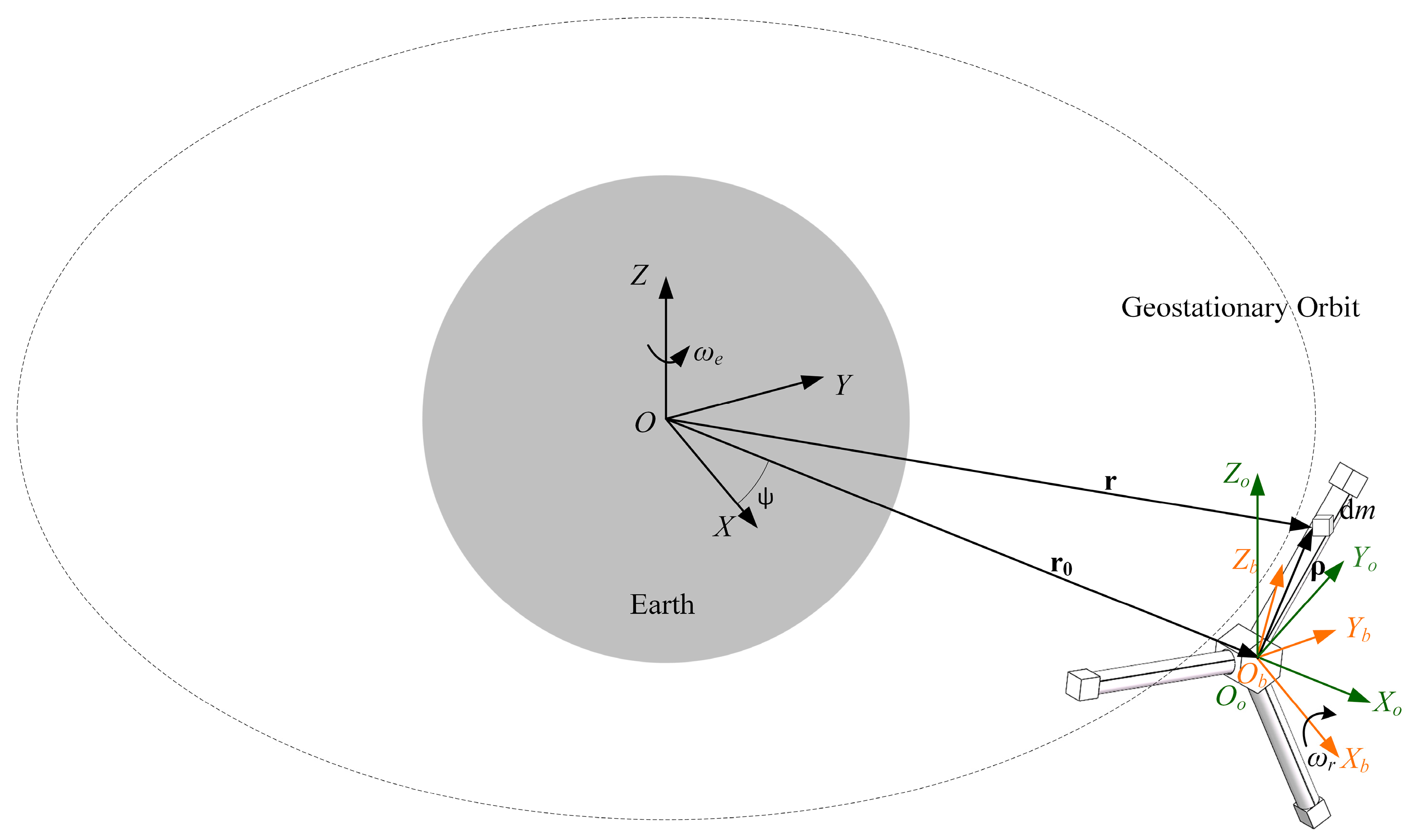
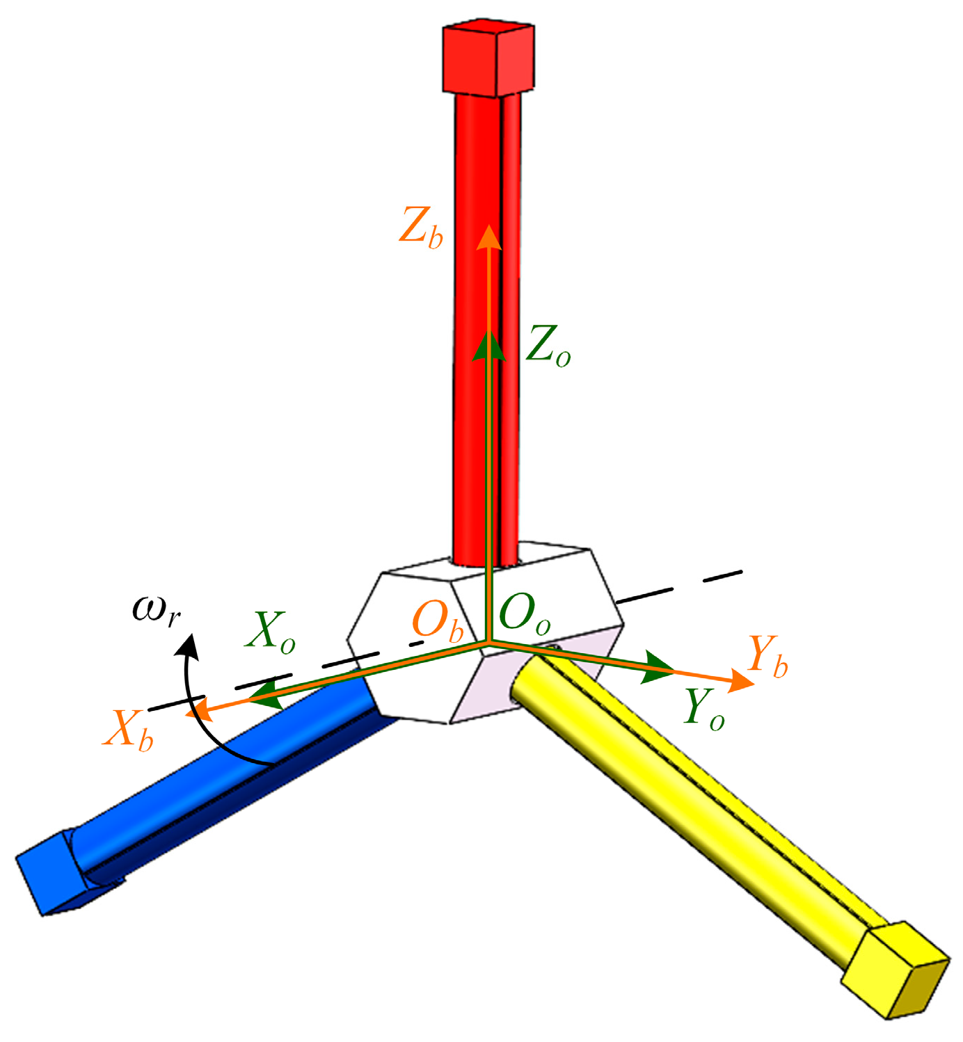
In order to describe the rigid body dynamics of a large space structure, the following three coordinate systems are defined, that is, the global coordinate system O-XYZ, the orbital coordinate system Oo-XoYoZo and the body-fixed coordinate system Ob-XbYbZb, as shown in Figure 1. In the global coordinate system O-XYZ, O is assumed to be the center of mass of the Earth, the OZ axis coincides with the Earth's rotation axis, and the OX and OY axes are in the equatorial plane. For the orbital coordinate system Oo-XoYoZo, the OoZo axis is parallel to the OZ axis, the OoYo axis represents the flight direction, and the OoXo axis can be determined by the right-handed rule, that is, the OOo direction. At the initial moment, the orbital coordinate system Oo-XoYoZo is parallel to the global coordinate system O-XYZ, and the body-fixed coordinate system Ob-XbYbZb coincides with the orbital coordinate system Oo-XoYoZo. When the space structure is disturbed by external disturbances, Oo-XoYoZo and Ob-XbYbZb are no longer coincident. At this moment, the rotation angle around ObXb axis is defined as yaw angle α , the rotation angles around ObZb axis is defined as pitch angle φ and the rotation angle around ObYb axis is defined as roll angle θ , respectively. The order of yaw-pitch-roll is often used in spacecraft. Therefore, the coordinate system Oo-XoYoZo rotates around the OoXo axis of an angle α first, then rotates around the OoZo axis of an angle φ and finally around the OoYo axis of an angle θ to obtain the coordinate system Ob-XbYbZb. The coordinate transformation matrix between the orbital coordinate system and the body-fixed coordinate system H o b is
H o b = cos θ cos φ cos θ sin φ cos α + sin θ sin α cos θ sin φ sin α + sin θ cos α sin φ cos φ cos α cos φ sin α sin θ cos φ sin θ sin φ cos α + cos θ sin α sin θ sin φ sin α + cos θ cos α
For any mass points at different positions on the space structure, the gravity is different because of their different positions relative to the center of the Earth. These forces produce a torque around the center of mass of the space structure, which is called gravity gradient torque. For a large space structure, as shown in Figure 1, Ob represents the structure centroid and Ob-XbYbZb coincides with the inertial principal axis of the structure. r 0 represents the position vector of point Ob in the global coordinate system O-XYZ, ρ represents the position vector of any mass point dm in the body-fixed coordinate system Ob-XbYbZb, and r represents the position vector of dm in the global coordinate system O-XYZ, which satisfy
r = r 0 + ρ
The absolute velocity of dm can be expressed as
r ˙ = r ˙ 0 + ω r × ρ = r ˙ 0 + ω ˜ r ρ
where ω r is rotating angular velocity of the space structure in the global coordinate system O-XYZ, r ˙ 0 is the absolute velocity of centroid Ob, and ω ˜ r is the antisymmetric matrix of ω r . The torque of momentum of the space structure projected on Ob-XbYbZb, L b can be expressed as
L b = V r b × r ˙ 0 b d m = m r 0 b × r ˙ 0 b + J ω r = m r ˜ 0 b r ˙ 0 b + J ω r
J = J x x J x y J x z J y x J y y J y z J z x J z y J z z = V ( ρ y b ) 2 + ( ρ z b ) 2 ρ x b ρ y b ρ x b ρ z b ρ x b ρ y b ( ρ x b ) 2 + ( ρ z b ) 2 ρ y b ρ z b ρ x b ρ z b ρ y b ρ z b ( ρ x b ) 2 + ( ρ y b ) 2 d m
where r 0 b and r ˙ 0 b are respectively the projection of r 0 and r ˙ 0 in Ob-XbYbZb, ω r b = [ ω x b   ω y b   ω z b ] T and ρ b = [ ρ x b   ρ y b   ρ z b ] T are respectively the projection of ω r and ρ in Ob-XbYbZb, J is the matrix of the moments of inertia of the space structure, and r ˜ 0 b is the antisymmetric matrix of r 0 b . J x x , J y y and J z z are respectively the moments of inertia of the corresponding axes. J x y , J x z and J y z are the corresponding products of inertia.
The projection of the external torque on the space structure in Ob-XbYbZb is defined as T b = [ T x b   T y b   T z b ] T . The relationship between T b and L b is [24]
d L b d t = J ω ˙ r b + ω ˜ b ( J ω r b ) = T b
where ω ˜ r b is the antisymmetric matrix of ω r b .
Eq. (6) is the attitude dynamic equation of the space structure. The projections of the orbital angular velocity vector in Oo-XoYoZo and Ob-XbYbZb are expressed as ω e o = [ 0 0 ω e ] T and ω e b , where ω e is orbital angular speed of the space structure. The relationship between them is
ω e b = H o b ω e o
The projection of the absolute attitude angular velocity of the space structure in Ob-XbYbZb is
ω r b = cos φ sin θ 0 cos θ sin φ 1 0 cos φ cos θ 0 sin θ α ˙ θ ˙ φ ˙ + ω e b
When the attitude angles of the space structure are small, Eq. (8) can be linearized as
ω r b = α ˙ φ ω e θ ˙ ω e φ ˙ + α ω e
Substituting Eq. (9) into Eq. (6) and ignoring the second-order small quantities lead to
I x x α ¨ ( I z z I x x I y y ) ω e θ ˙ + ( I z z I y y ) ω e 2 α = T x b I y y θ ¨ + ( I z z I x x I y y ) ω e α ˙ + ( I z z I x x ) ω e 2 θ = T y b I z z φ ¨ I z z ω ˙ e = T z b
It can be seen from Eq. (10) that the pitch motion of the space structure is decoupled from the roll and yaw motions under small angles assumption, while the roll motion and yaw motion are coupled with each other.
As shown in Figure 1, if only the gravity gradient torque is considered, the external torque in Eq. (6) can be expressed as
T g b = V ρ b × μ e r 0 b + ρ b | r 0 b + ρ b | 3 d m = V μ e ( ρ b × r 0 b ) | r 0 b + ρ b | 3 d m
where Earth is assumed to be a homogeneous standard sphere and μ e represents Earth constant.
Considering | ρ b | | r 0 b | , the Taylor series expansion of 1 / | r 0 b + ρ b | 3 is carried out and retained to the o ( | r 0 b | 5 ) term to obtain
1 | r 0 b + ρ b | 3 1 r 0 3 3 r 0 b ρ b ρ 0 5 + o ( r 0 5 )
where r 0 = | r 0 b | . By substituting Eq. (12) into Eq. (11), one has
T g b = μ e r 0 3 V ρ b d m × r 0 b + 3 μ e r 0 5 V r 0 b ρ b ρ b × r 0 b d m = 3 μ e r 0 5 r ˜ 0 b J r 0 b
According to the definitions of Oo-XoYoZo and Ob-XbYbZb, the projections of r 0 in these two coordinate systems are denoted by r 0 o = [ r 0 0 0 ] T and r 0 b = H o b r 0 o = r 0 [ cos θ cos φ sin φ sin θ cos φ ] T . Substituting r 0 b into Eq. (13) leads to
T g b = 3 μ e 2 r 0 3 ( J y y J z z ) sin θ sin 2 φ ( J x x J z z ) sin 2 θ cos 2 φ ( J x x J y y ) cos θ sin 2 φ
By substituting Eq. (14) into Eq. (10), the linearized attitude dynamic equations of the space structure under the gravity gradient torque can be expressed as
J x x α ¨ ( J z z J x x J y y ) ω e θ ˙ + ( J z z J y y ) ω e 2 α = 0 J y y θ ¨ + ( J z z J x x J y y ) ω e α ˙ + 4 ( J z z J x x ) ω e 2 θ = 0 J z z φ ¨ + 3 ω e 2 ( J y y J x x ) φ = J z z ω ˙ e

2.2. Gravity Gradient Stability Criterion

While the space structure moves on a standard circular orbit, i.e. ω ˙ e = 0 rad / s 2 , the pitch motion of the space structure is critically stable if the following condition is satisfied
J y y > J x x
It can be obtained by the first and second equations in Eq. (15) in Laplace transform
s 2 + 4 k y ω e 2 ( k y 1 ) ω e s ( 1 k x ) ω e s s 2 + k x ω e 2 θ ( s ) α ( s ) = 0 0
where k y = ( J z z J x x ) / J y y and k x = ( J z z J y y ) / J x x . And the characteristic equation of Eq. (17) is
s 4 + ( 1 + 3 k y + k y k x ) ω e 2 s 2 + 4 k y k x ω e 4 = 0
According to Routh criterion [25], when k y and k x satisfy the following conditions, there is no positive root in the real part of Eq. (18). The yaw and roll motions of the space structure are critically stable if the following conditions are satisfied as well
k y k x > 0 1 + 3 k y + k y k x > 4 k y k x
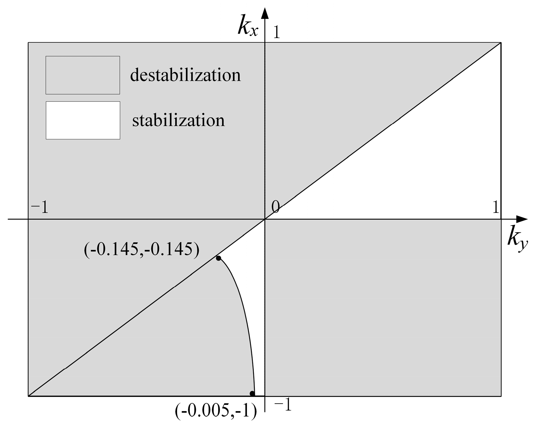
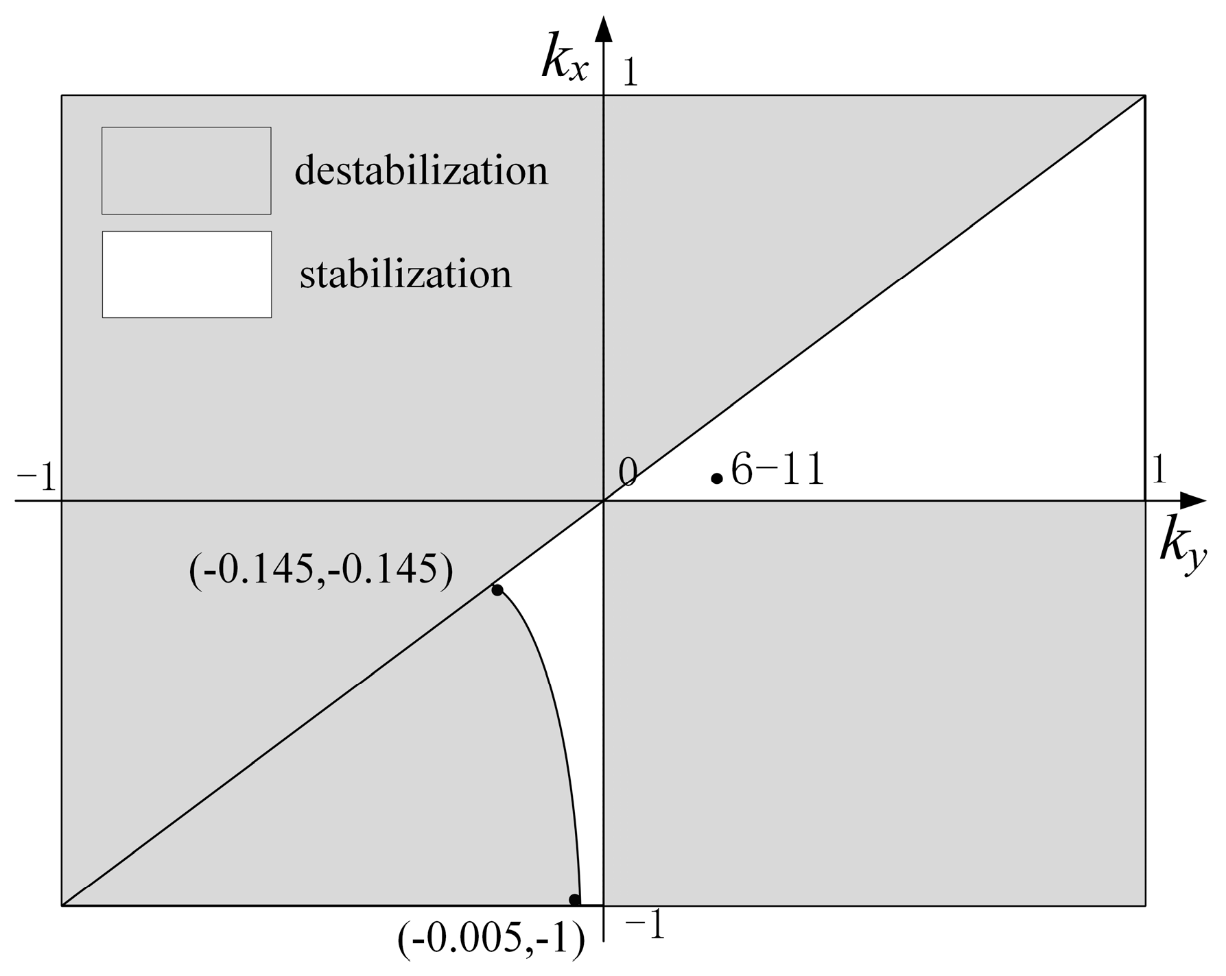
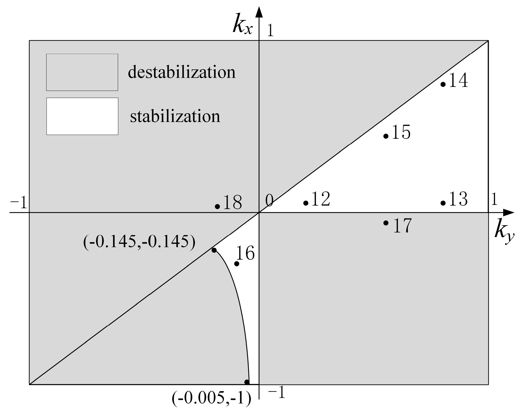
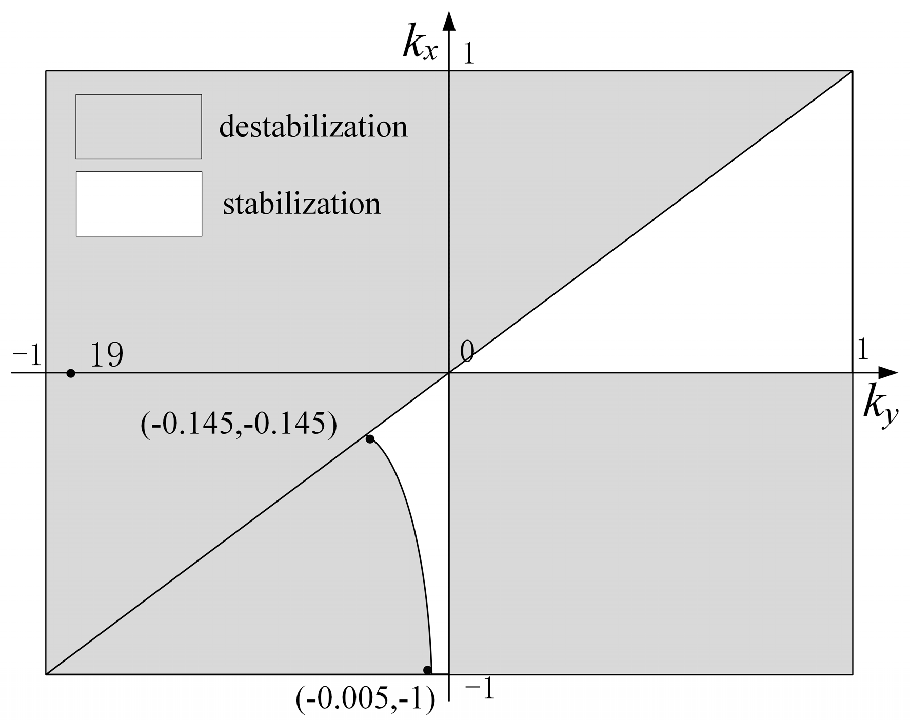
Eqs. (16) and (19) constitute the gravity gradient stability criteria of the large space structure, as shown in Figure 2.
For a large space structure, the sum of the moments of inertia of any two axes must be greater than the moment of inertia of the third axis, so the value ranges of k y and k x are [-1, 1]. It can be seen from Figure 2 that when k y > 0 and k x > 0 , the stability criteria is k y > k x , i.e. J z z > J y y > J x x . When k y < 0 and k x < 0 , the stable boundary conditions are determined by J y y > J x x > J z z and 1 + 3 k y + k y k x > 4 k y k x .

3. Dynamic Modeling for Simulations

In this section, in order to describe the large overall motion of the large rigid space structure, an orbital dynamic model of the large space structure is established via NCF. The corresponding dynamic equations are solved via the generalized α algorithm.

3.1. Rigid Body Modeling

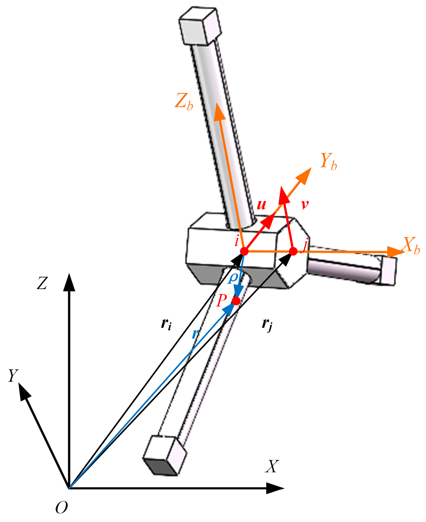
The NCF uses two fixed points on the rigid body and two non-coplanar unit vectors as generalized coordinates to describe the spatial motion of the space structure. The above generalized coordinates are given in the global coordinate system, as shown in Figure 3.
As shown in Figure 3, a space structure described via NCF has the following 12 generalized coordinates [26]
q = r i T r j T u T v T T
where r i and r j are respectively the global position vectors of points i and j, where i is the mass center of the structure, and u and v are two non-coplanar unit vectors. For convience, r j b = ( r j r i ) / L , u and v are all defined as the unit vectors of axes ObXb, ObYb and ObZb, where L is the distance between two points i and j. The position vector of any point P on the space structure in the body-fixed coordinate system is denoted as [ c 1 c 2 c 3 ] T . Then the position vector ρ of this point in the body-fixed coordinate system can be expressed as
r r i = ρ = c 1 r j b + c 2 u + c 3 v
In this way, the position vector of any point P on the space structure in the global coordinate system can be expressed as
r = r i + c 1 r j b + c 2 u + c 3 v = ( 1 c 1 L ) I c 1 L I c 2 I c 3 I r i r j u v = C q
where I is a third-order identity matrix.
The mass matrix of the space structure described via NCF is
M = ( m + J x ¯ L 2 2 m x G b L ) I ( m x G b L J x ¯ L 2 ) I ( m y G b J x y L ) I ( m z G b J x z L ) I ( m x G b L J x ¯ L 2 ) I ( J x ¯ L 2 ) I ( J x y L ) I ( J x z L ) I ( m y G b J x y L ) I ( J x y L ) I ( J y ¯ ) I ( J y z ) I ( m z G b J x z L ) I ( J x z L ) I ( J y z ) I ( J z ¯ ) I
where m is the mass of the space structure. x G b , y G b , and z G b are the local coordinates of the center of mass of the space structure. J x ¯ , J y ¯ , and J z ¯ are related to the moments of inertia of the space structure, given by
J y ¯ + J z ¯ = J x x J x ¯ + J z ¯ = J y y J x ¯ + J y ¯ = J z z
By establishing the model of the space structure via the NCF, the mass matrix and generalized external force of the system can be obtained. At the same time, considering the inherent constraints of rigid body Φ ( q ) = 0 as shown in Eq. (25),
| r j r i | L = 0 , | u | 1 = 0 , | v | 1 = 0 , ( r j r i ) T u = 0 ,   ( r j r i ) T v = 0 ,   u T v = 0.
the dynamic equation of the rigid body system in the global coordinate system can be established by using the Lagrange multiplier method in the following way
M q ¨ + Φ , q T λ = Q ( q , q ˙ ) Φ ( q ) = 0
where λ is the vector of Lagrange multiplier, Q is the vector of generalized external force including gravity gradient torque of the system, and Φ , q T represents the Jacobi matrix of the kinematic constraints of the system, where Φ , q = Φ / q .

3.2. Orbital Dynamics

As shown in Figure 1, for any point P on the space structure, r represents the position vector of P in the global coordinate system O-XYZ, and r o represents the position vector of this point in the orbital coordinate system Oo-XoYoZo. Supposing the origin of Oo-XoYoZo coincides with the one of Ob-XbYbZb, one obtains
r = H o g r o + r 0
where H g o is the attitude transformation matrix from the orbital coordinate system to the global coordinate system, where
H o g = cos ψ sin ψ 0 sin ψ cos ψ 0 0 0 1
where ψ is the rotation angle of the orbital coordinate system relative to the global coordinate system. According to Eq. (27), the velocity and acceleration of point P are obtained by calculating the first derivative and the second derivative of r with respect to time as follows
r ˙ = H ˙ o g r o + H o g r ˙ o + r ˙ 0 r ¨ = H ¨ o g r o + 2 H ˙ o g r ˙ o + H o g r ¨ o + r ¨ 0
where
r ˙ 0 = ω e × r 0 = ω ˜ e r 0 r ¨ 0 = ω e 2 r 0
where ω ˜ e is the antisymmetric matrix generated by ω e .
The relationship between the generalized coordinate q of the space structure in the global coordinate system and the generalized coordinate q o in the orbital coordinate system is
q = H q o + R
where R = [ r 0 T r 0 T 0 T 0 T ] T , H = diag [ H o g H o g H o g H o g ] and q o = [ r i o T r j o T u o T v o T ] .
According to the Eq. (31), the generalized velocity and generalized acceleration of the structure in the global coordinate system are respectively
q ˙ = H ˙ q o + H q ˙ o + R ˙ q ¨ = H ¨ q o + 2 H ˙ q ˙ o + H q ¨ o + R ¨
By substituting Eq. (32) into Eq. (26), the dynamic equation of the space structure in the orbital coordinate system can be expressed as [27]
M ^ q ¨ o + C ^ q ˙ o + K ^ q o + H T M R ¨ + Φ , q o T λ = F ^ g Φ ( q o ) = 0
where M ^ = H T M H , C ^ = 2 H T M H ˙ , K ^ = H T M H ¨ , F ^ g = H T F g , and F g is the vector of universal gravitation of the space structure as follows
F g = μ e m C T r i | r i | 3

3.3. Solutions

This section uses a generalized α implicit algorithm [28] developed on the basis of Newmark's method to solve Eq. (33).
The iterative solution process using the difference method is as follows
M ^ q ¨ o n + 1 + C ^ q ˙ o n + 1 + K ^ q o n + 1 + H T M R ¨ + Φ , q o T λ n + 1 = F ^ g Φ ( q o n + 1 , t n + 1 ) = 0
The relationship between q o n + 1 and q ˙ o n + 1 is shown as
q o n + 1 = q o n + h q ˙ o n + h 2 2 ( 1 2 β ) q ¨ o n + h 2 β q ¨ o n + 1 q ˙ o n + 1 = q ˙ o n + h ( 1 γ ) q ¨ o n + h γ q ¨ o n + 1
where β and γ are the vector parameters of the algorithm and h is the iteration step of the algorithm. β 1 / 4 , γ = 1 / 2 are generally taken to obtain a more stable algorithm.
On this basis, by introducing the new algorithm auxiliary parameter column vector a, Eq. (36) can be rewritten as
q o n + 1 = q o n + h q ˙ o n + h 2 ( 1 2 β ) a n q ˙ o n + 1 = q ˙ o n + h ( 1 γ ) a n
where a is determined by the following relationship
( 1 α m ) a n + 1 + α m a n = ( 1 α f ) q ¨ o n + 1 + α f q ¨ o n a 0 = q ¨ o 0
The values of the parameters in Eq. (37) are defined as follows
α m = 2 ρ ˜ 1 ρ ˜ + 1 , α f = ρ ˜ ρ ˜ + 1 , β = 1 4 ( 1 + α f α m ) ,   γ = 1 2 + α f α m .
where ρ ˜ [ 0 , 1 ] is the spectral radius of the generalized α algorithm. The higher the value of ρ ˜ is, the smaller the energy dissipation generated by the generalized α algorithm will be.

4. Cases Study for Gravity Gradient Stability Analysis

In this section, various numerical examples are presented to study the influence of different disturbances on the gravity gradient stability of a large rigid space structure and to verify the rationality of the dynamic model and gravity gradient stability criterion. For all the cases in this section, the body-fixed coordinate system coincides with the orbital coordinate system for the initial state without any disturbance. Therefore, the dynamic responses of the large space structure are presented in the orbital coordinate system.

4.1. A symmetrical Revolution Space Structure under Small Disturbance Angles

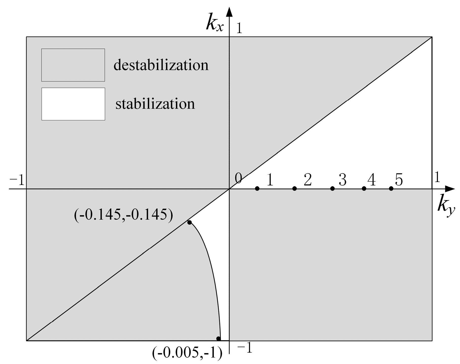
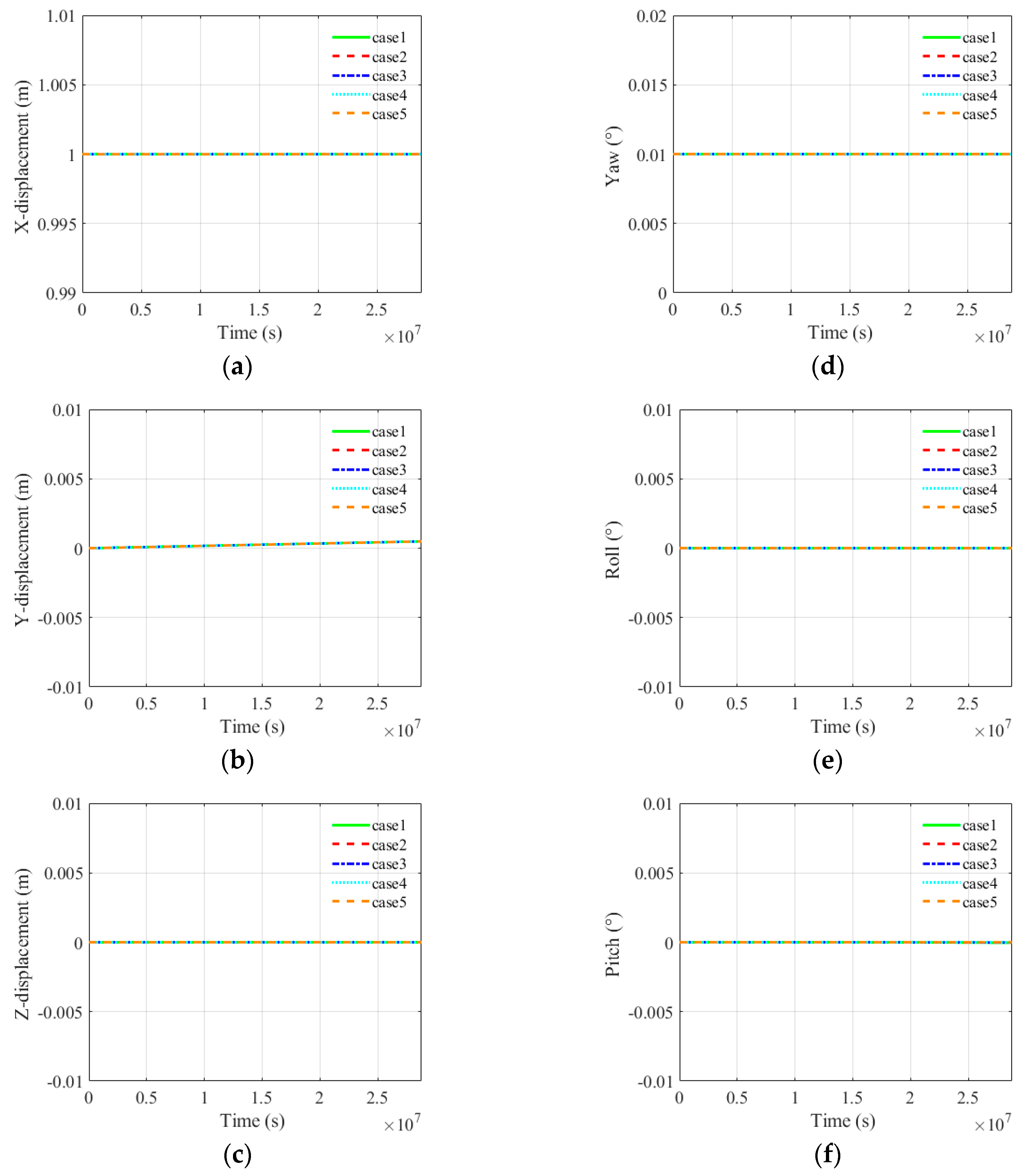
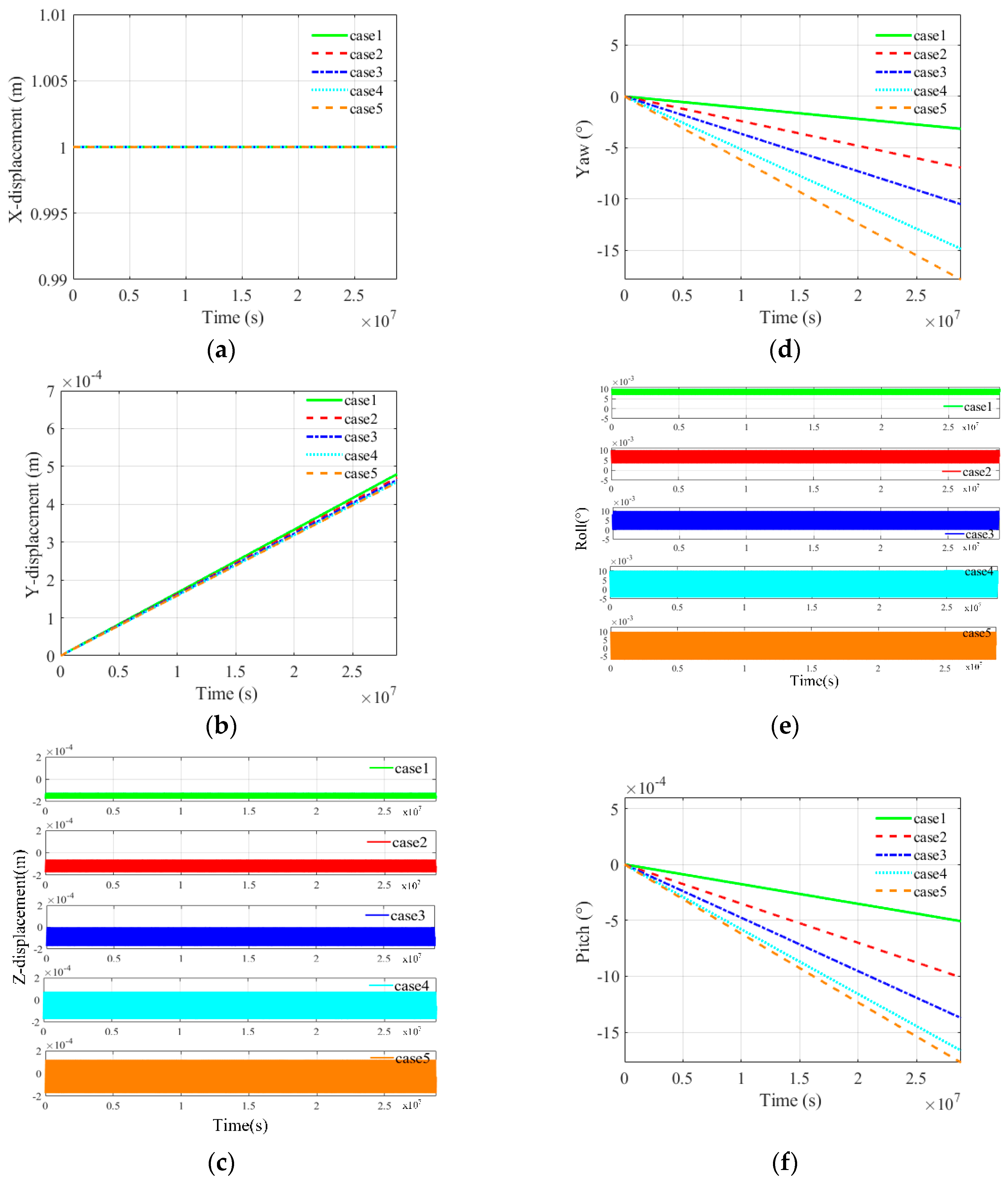
This subsection explores the gravity gradient stability of a symmetrical revolution space structure, that is, J y y = J z z > J x x for the structure, under different small disturbance angles, as shown in Table 1 and Figure 4. For each case, three different initial small disturbance angles, that is, 0.01° in yaw, roll and pitch angles, respectively, are taken into account, as shown in Table 2.
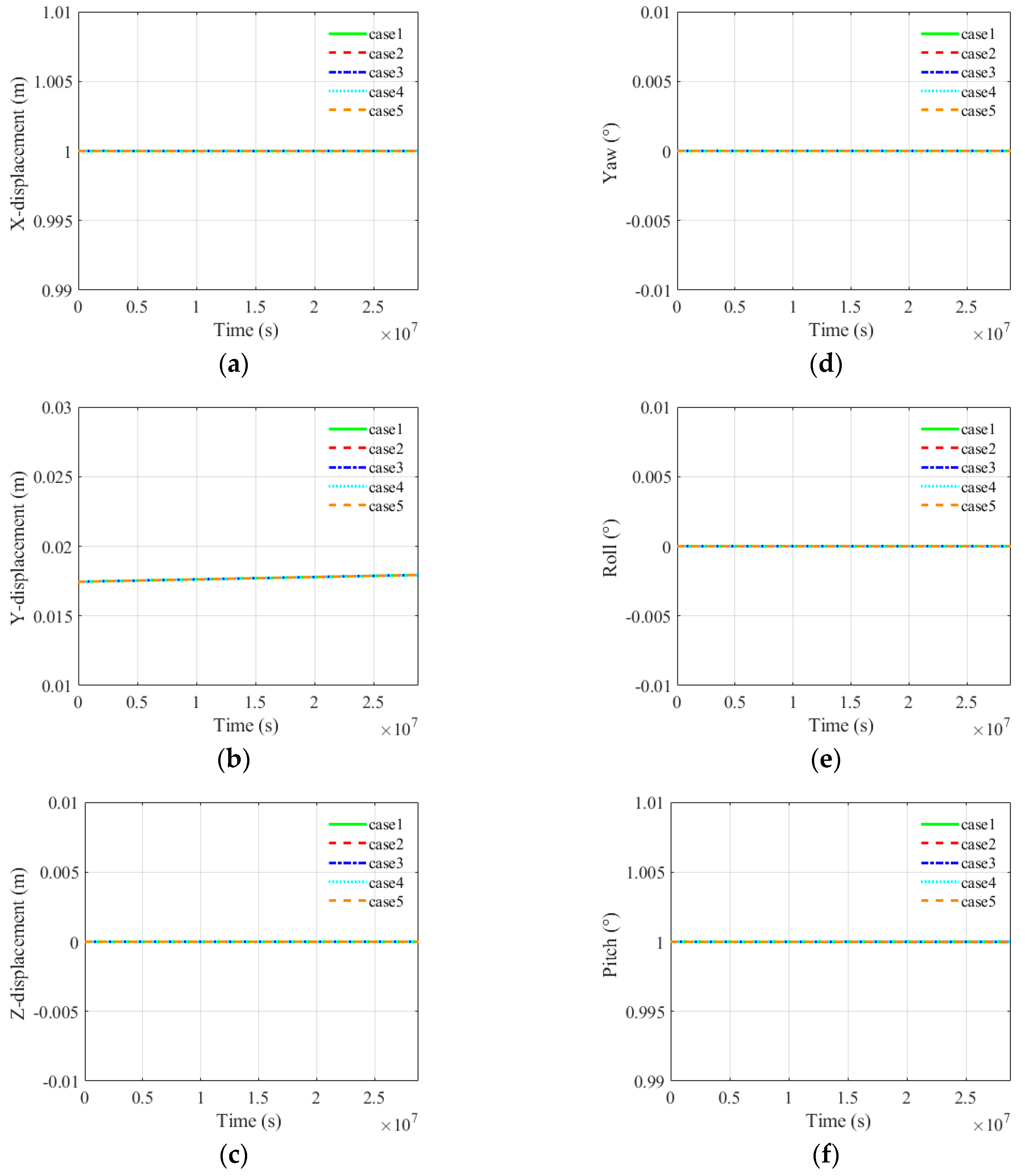
Figure 5, Figure 6 and Figure 7 present the dynamic responses of the large space structure for each case under different small initial disturbance angles. As shown in Figure 5 and Figure 7, when the initial disturbance angles are small angles in either pitch or yaw angle, the displacement of node j in X, Y and Z directions and the variation of yaw, roll and pitch angles are almost invariant. When the initial disturbance angle is a small angle in roll angle, as shown in Figure 6, the yaw angle of these five cases has a certain change and the variation ranges of dynamic responses from case 1 to case 5 have an increasing trend. It can be concluded that for a symmetrical revolution space structure, when the initial disturbance angle is a small roll angle, the motion of space structure is easy to get unstable and initial configurations may easily affect the attitudes of the large space structure.

4.2. A symmetrical Revolution Space Structure under Large Disturbance Angles

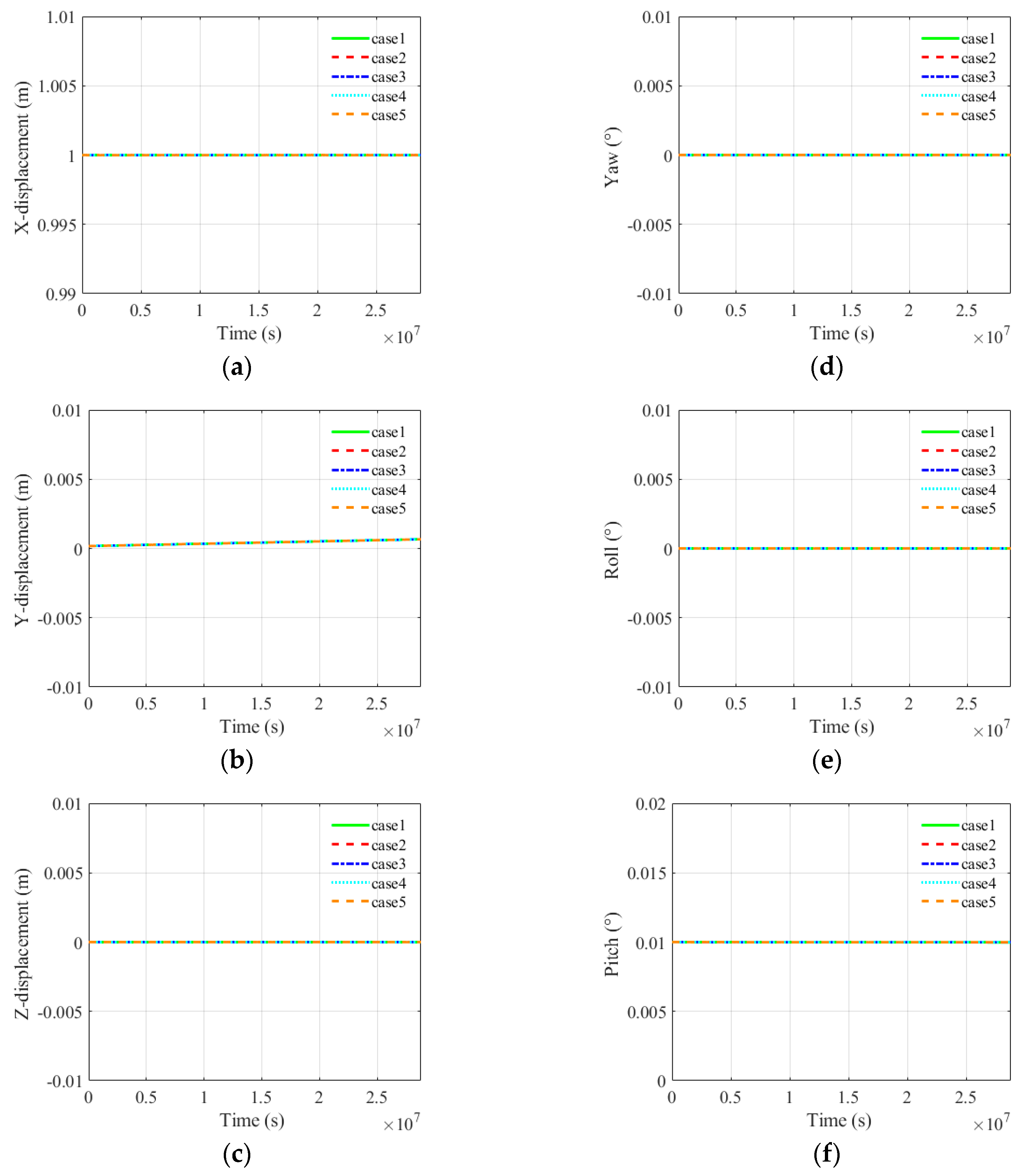
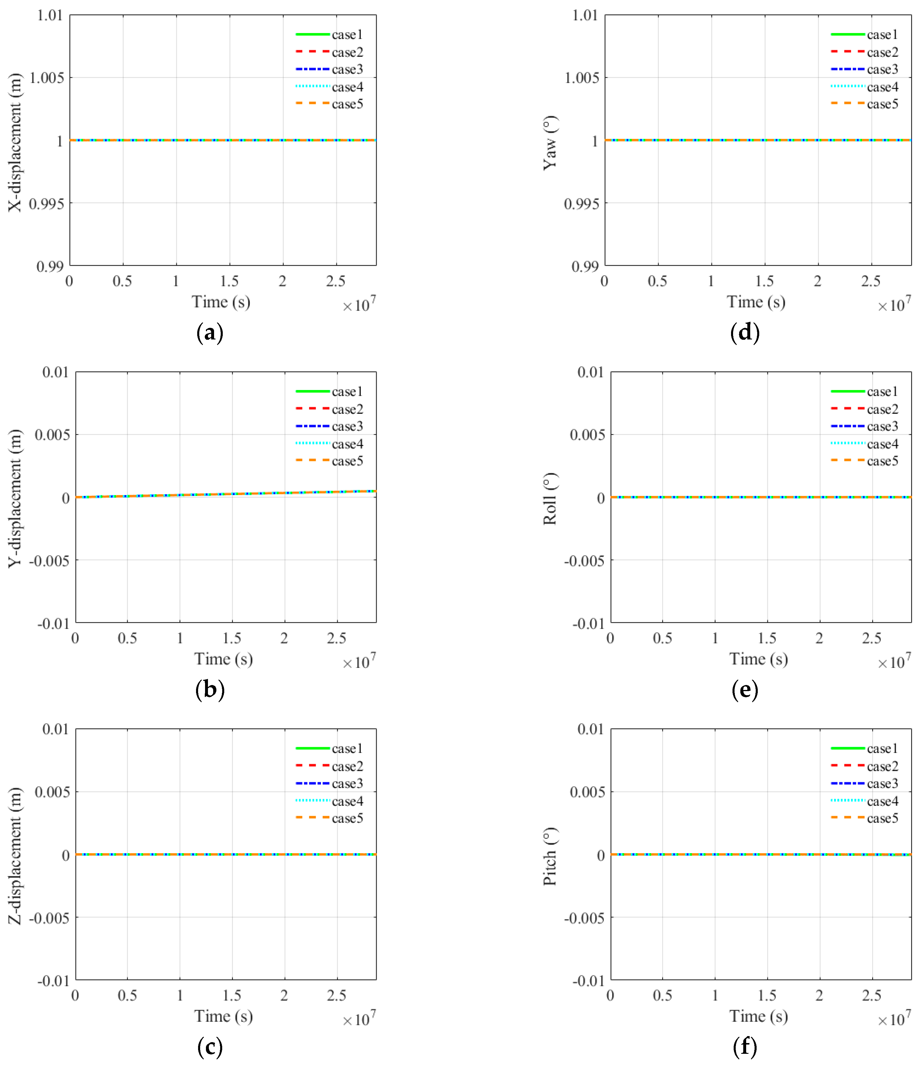
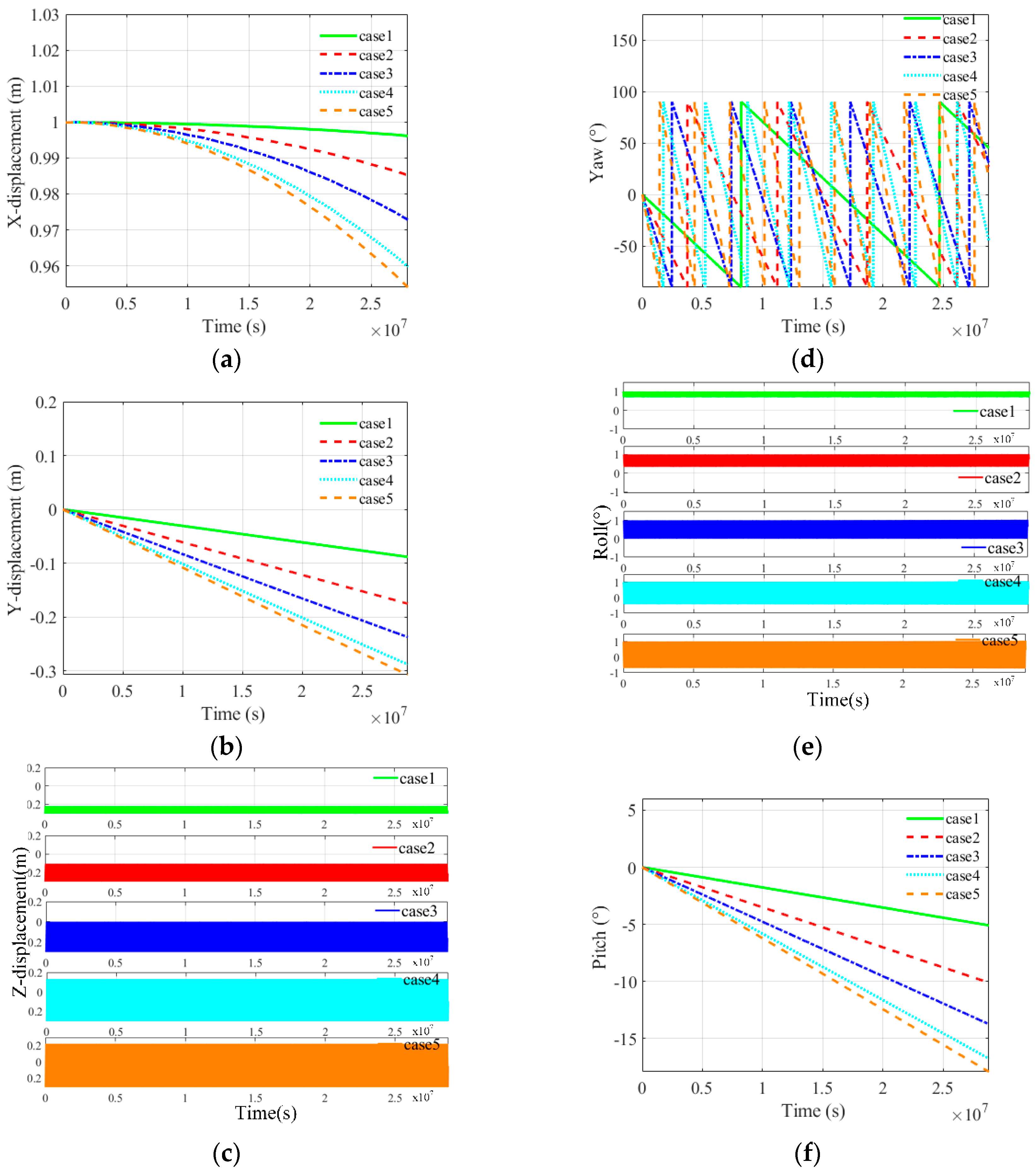
This subsection explores the gravity gradient stability of a symmetrical revolution space structure under different large disturbance angels. The moments of inertia are the same as the ones in subsection 4.1. For each case, three different initial large disturbance angels, that is, 1° in Yaw, Roll and Pitch angles, respectively, are taken into account, as shown in Table 3.
Figure 8, Figure 9 and Figure 10 present the dynamic responses of the large space structure for each case under different large initial disturbance angles. As shown in Figure 8 and Figure 10, when the initial disturbance angles are large angles in either pitch or yaw angle, the large space structure keeps stable. When the initial disturbance angle is 1° in roll angle, Figure 9(d) shows that the yaw angles for these five cases change dramatically, from -90° to 90°, which indicates that the space structure is undergoing a tumbling motion. From Figure 9(a), (b), (c), (e) and (f), other kinds of dynamic responses have different degree of change and the variation ranges of case 1 to case 5 have an increasing trend. It shows that the space structure gets unstable when the initial disturbance is a large angle in roll angle.
By comparing the results in subsections 4.1 and 4.2, it can be seen that when the initial disturbance angle is yaw or pitch angle, the movement of the space structure is relatively stable, while when the initial disturbance angle is roll angle, the space structure is easy to become unstable. Figure 6 and Figure 9 show that as the initial disturbance of roll angle increases, the space structure turns more unstable. It also can be observed that the stability of case 1 is better than the other cases. This phenomenon suggests that both initial disturbance angle and the moments of inertia affect the gravity gradient stability of the space structure. Therefore, in the following two subsections, two different sets of cases are considered to study the influence of initial disturbance angles and the position in different stabilization or unstabilization regions.

4.3. A Stable Space Structure under Different Initial Disturbance Angles

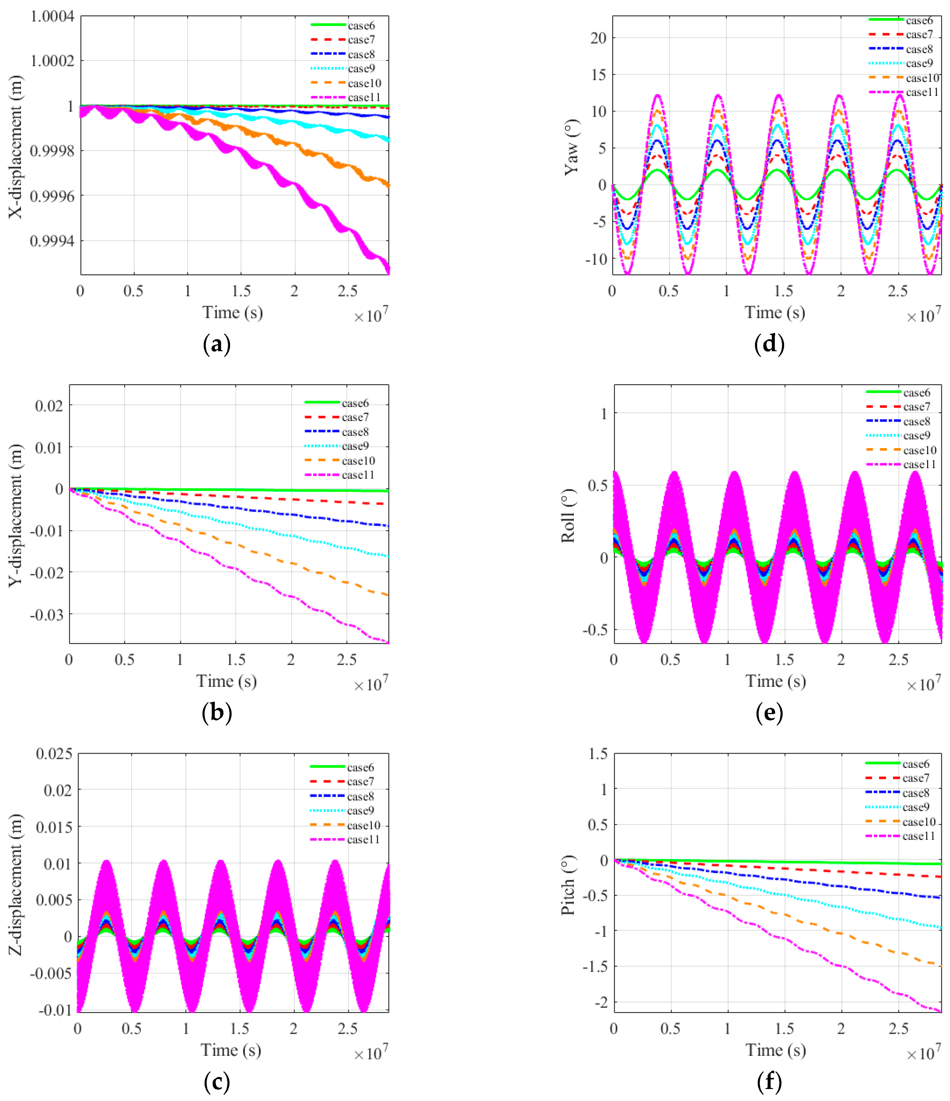
In this subsection, the influence of the initial roll angle on the stability of the space structure is studied. The moments of inertia of the space structure for these cases are shown in Table 4 and Figure 11, where Jxx < Jyy < Jzz. For each case, six different roll angles, that is, from 0.1° to 0.6°, are taken into account, as shown in Table 5.
Figure 12 presents the dynamic responses of the large space structure for cases 6-11 under different initial disturbance angles. Figure 12(c), (d) and (e) show that the displacement of node j in Z direction and the variation of yaw and roll angle are all periodic. Figure 12(a), (b) and (f) shows the displacement of node j in X and Y directions and the variation of pitch angle increase with the time but slightly. As a result, the motion of these cases can be considered relatively stable. As shown in Figure 12, the variation ranges of dynamic responses from case 6 to case 11 have an increasing trend. Hence, it can be known that that the larger the initial roll angle is, the more unstable the space structure will be. The initial disturbance angle of the roll angle should be as small as possible in order to keep the stability of the large space structure.

4.4. A Large Space Structure at Different Stabilization and Unstabilization Regions

In this subsection, the influence of the moments of inertia on the stability of the large space structure is studied by taking seven different cases at the stabilization and unstabilization regions into consideration. The moments of inertia for these cases are shown in Table 6 and Figure 13.
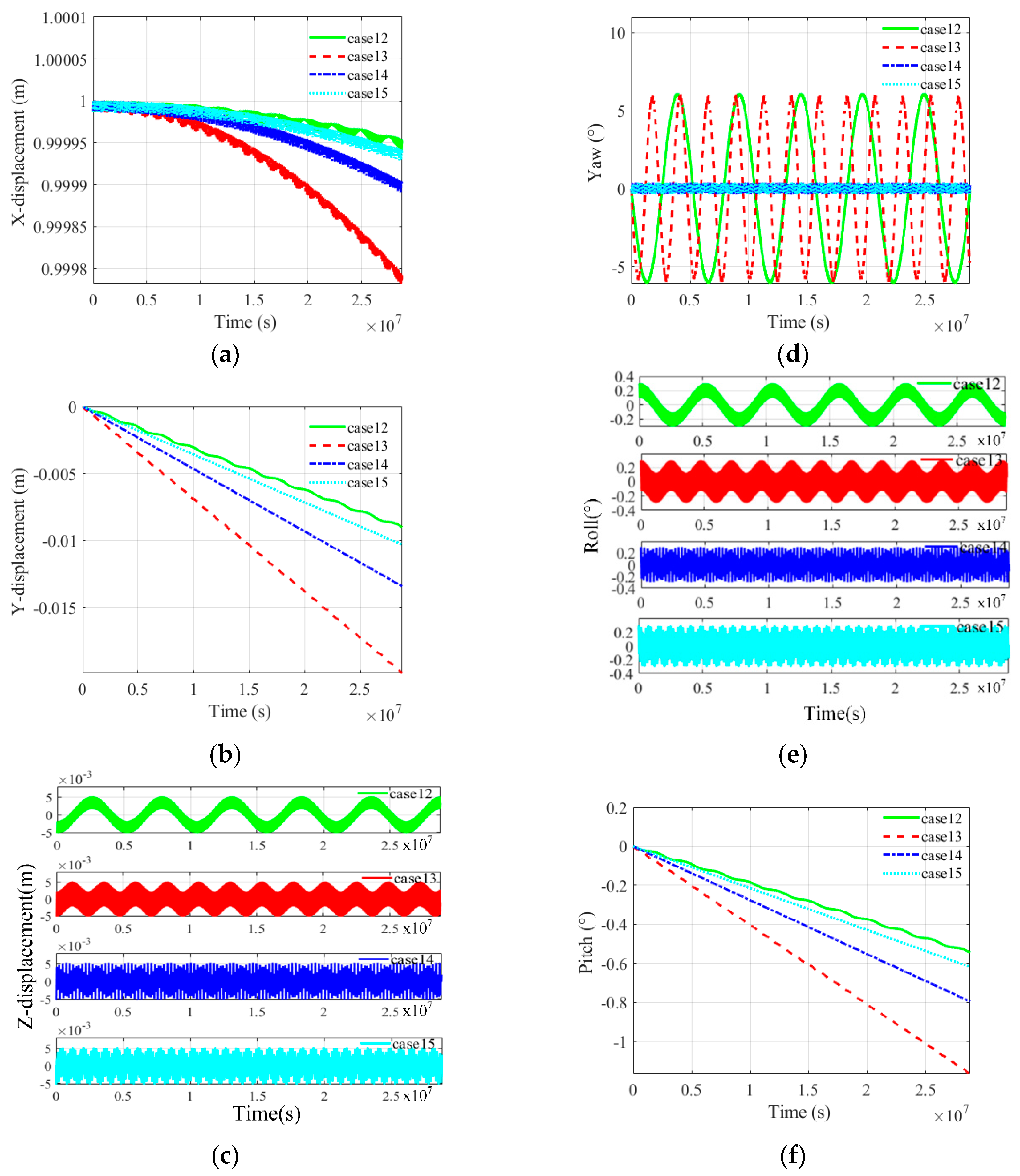
Figure 14 presents the dynamic responses of the large space structure for cases 12-15 at different stabilization regions. For each case, the initial disturbance angle is 0.3° in roll angle. Figure 14(c), (d) and (e) show that the displacement of node j in Z direction and the variation of yaw and roll angles are all periodic. Figure 14(a), (b) and (f) show that the displacements of node j in X and Y directions and the variation of pitch angle increase slightly with time. Therefore, the motion of the large space structure for these cases can be regarded relatively stable. The comparation of these four cases shows that the variation ranges of the dynamic responses of case 12 is smallest, and the ones of case 14 is smaller than those of case 13. The results indicate that when k x of a large space structure is constant, the stability of the structure will get worse with an increase of k y . Meanwhile, when k y is constant, the stability of the structure will become better with an increase of k x . Therefore, in order to improve the gravity gradient stability of a large space structure, the moments of inertia of the structure should be designed to statify k x = k y 0 as much as possible.
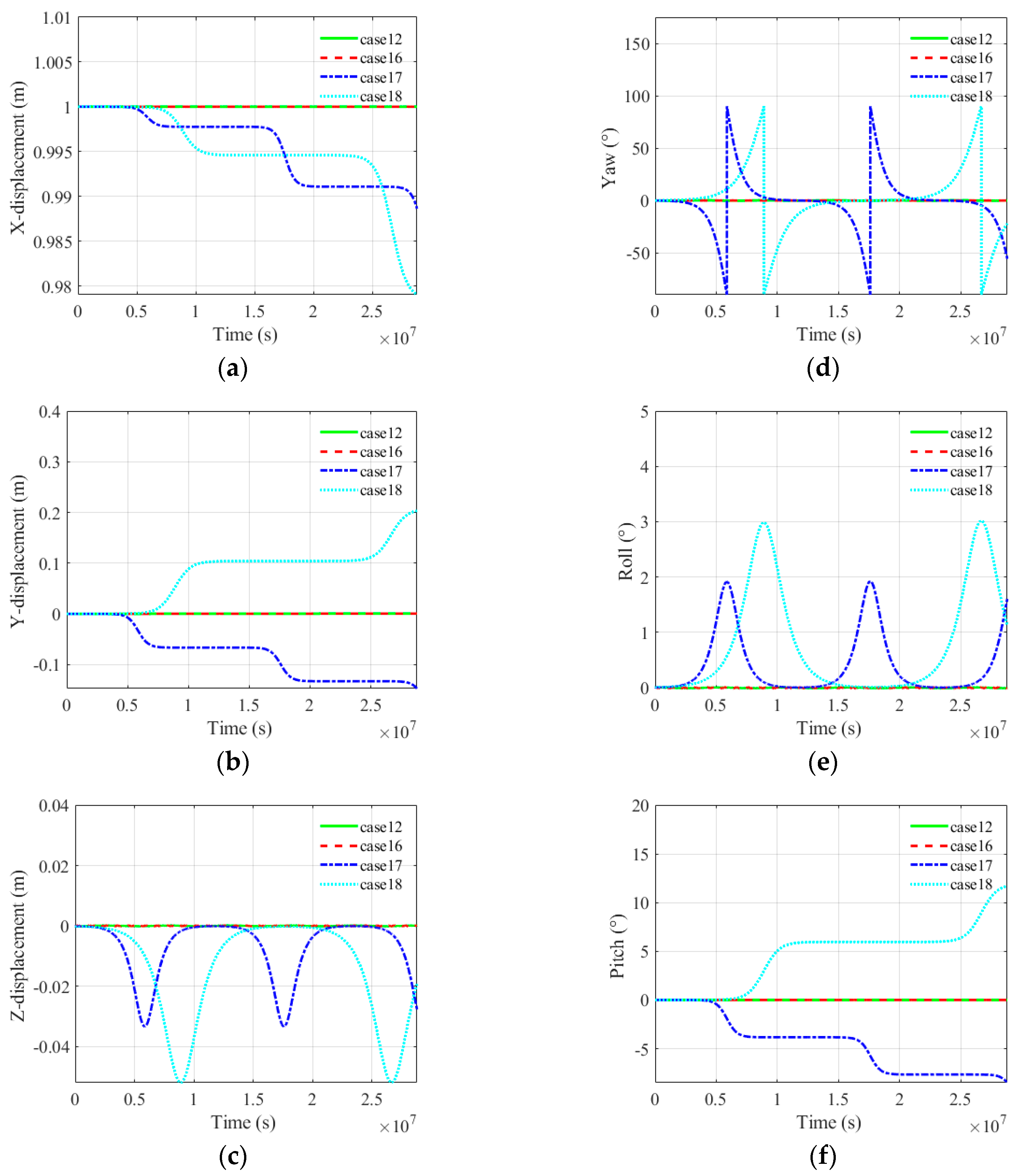
Figure 15 presents the dynamic responses of the large space structure for case 12 and cases 16-18 at different stabilization and unstabilization regions. For each case, the initial disturbance angle is 0.01° of roll angle. As shown in Figure 15, the displacement of node j in X, Y and Z directions and the variation of yaw, roll and pitch angles of cases 12 and 16 are almost invariant, while the ones of cases 17 and 18 have extremely large variations. From the comparation of these four cases it can be easily observed that for small disturbance angle, the cases at the unstabilization region will easily get unstable while the cases at the stabilization region keep stable. The phenomena verify the universality and rationality of the dynamic model and the accuracy of the gravity gradient stability criterion.

5. Stability Analysis of a Spinning Structure under the Influence of Gravity Gradient

This subsection studies the stability of a spinning space structure under the influence of gravity gradient. Figure 16 shows the schematic diagram of the spinning structure and its spinning axis, that is, the ObXb axis, which points to the center of Earth with a spinning angular speed of ω r = 600 r / min . The moments of inertia of the spinning space structure are shown in Table 7 and Figure 17.
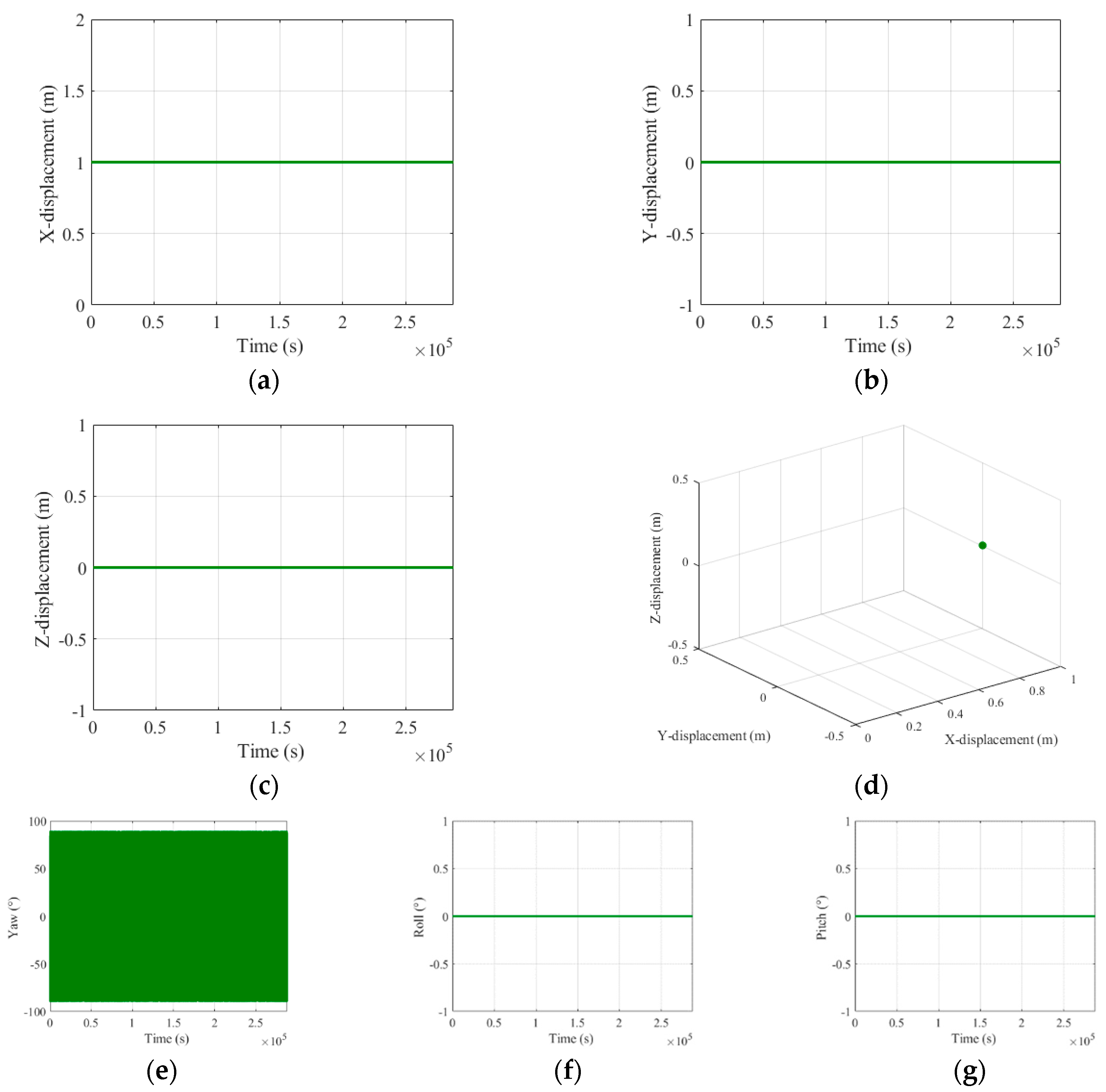
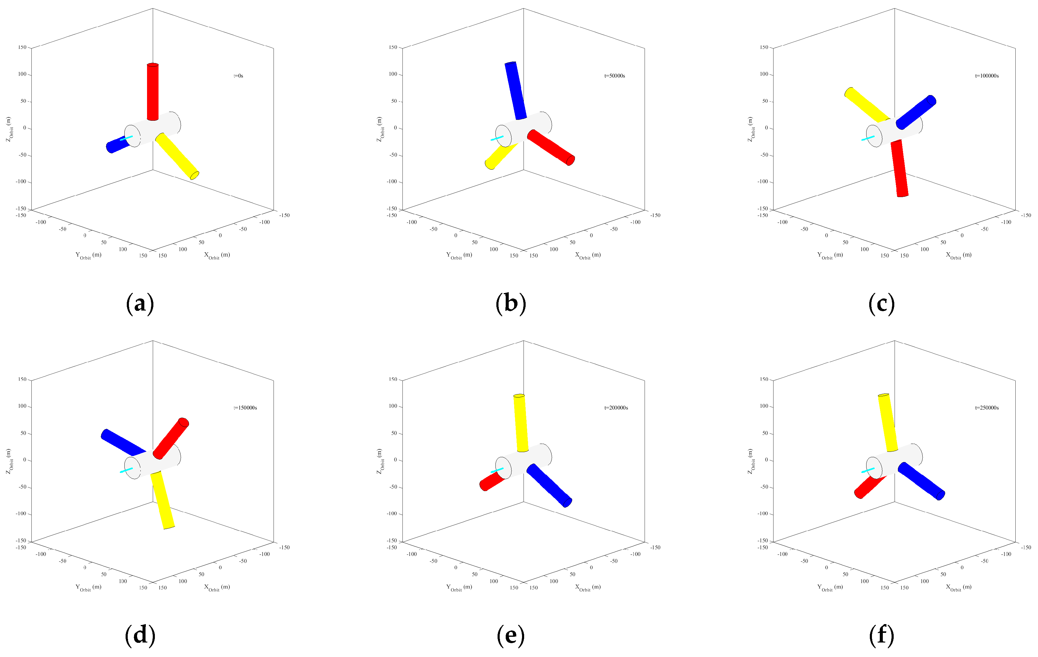
Figure 18 presents the dynamic responses of the spinning structure without considering gravity gradient torque and Figure 19 illustrates the configuration diagrams of spinning structure at different moments. As shown in Figure 18, when the gravity gradient torque is neglected, the spinning structure keeps stable as J x x > J y y = J z z . Figure 18(d) shows the trajectory of the node j and indicates that there is no motion of the node j. From Figure 19 it can also be observed that the spinning structure only rotates around the spinning axis.
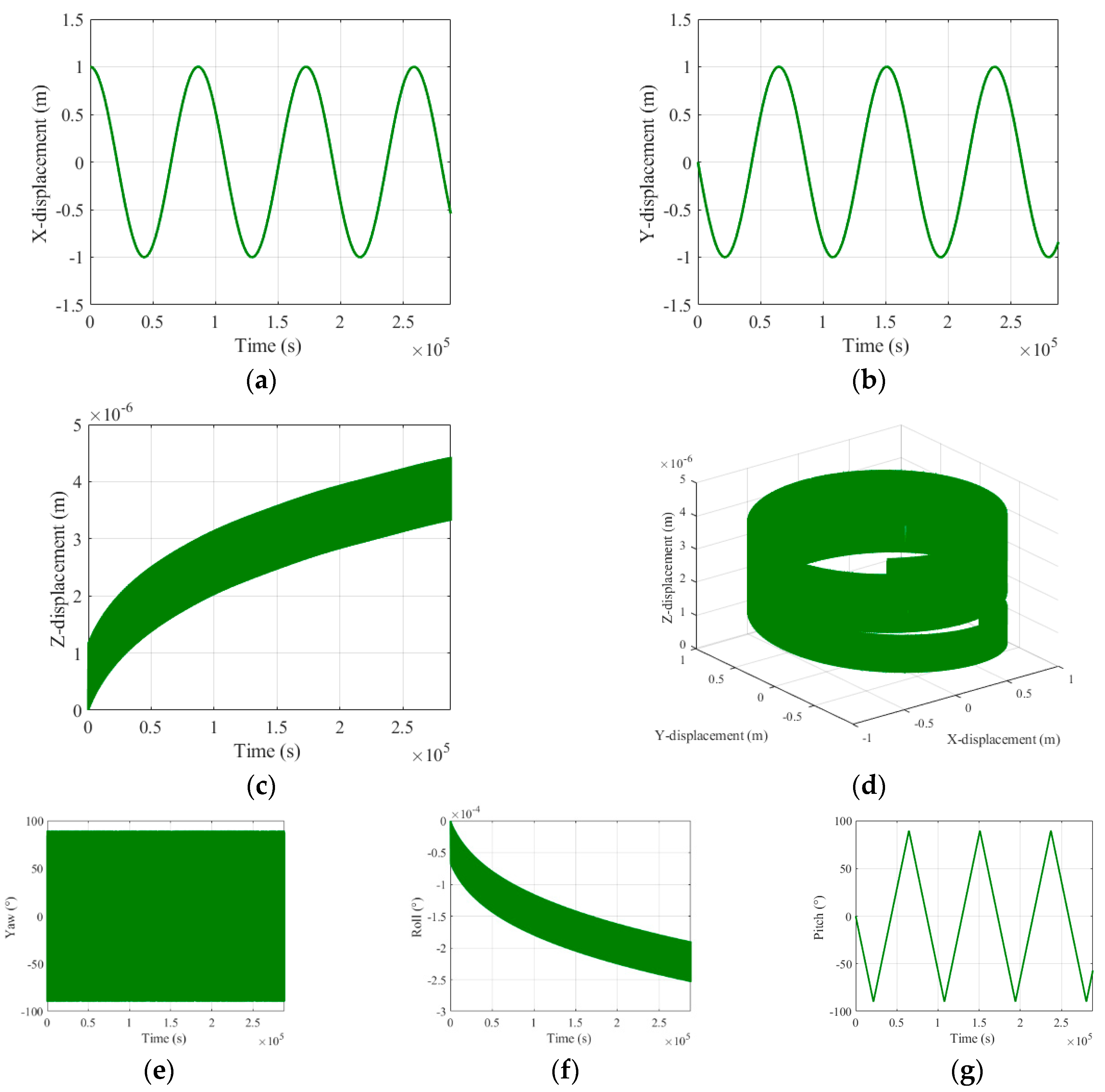
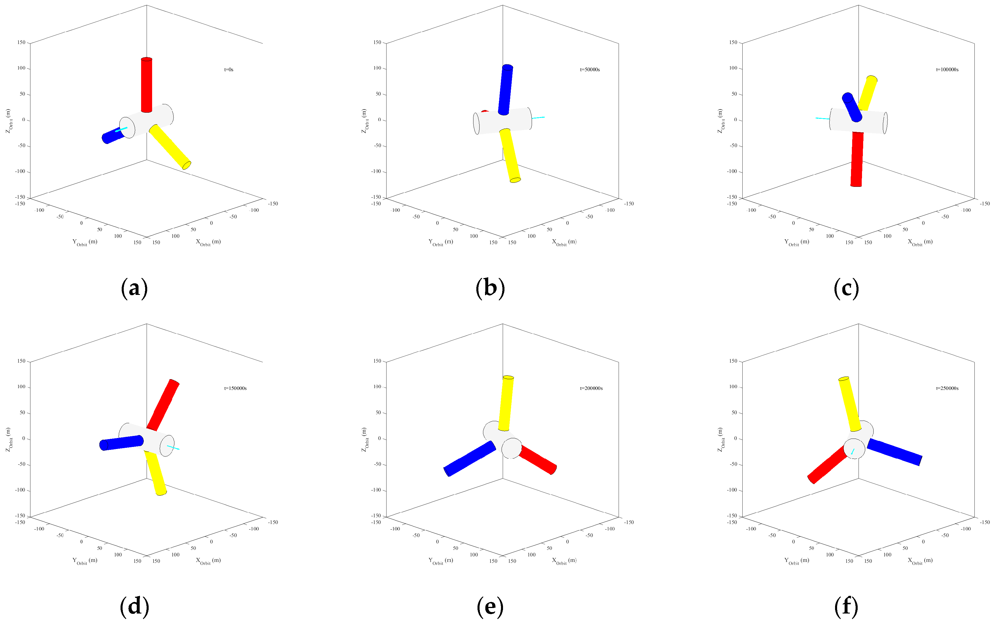
Figure 20 illustrates the dynamic responses of the spinning structure considering gravity gradient torque and Figure 21 gives the corresponding configuration diagrams of the spinning structure at different moments. As is shown in Figure 20, when the gravity gradient torque is considered, the displacement of node j in X and Y directions and the pitch angle are all periodical. Figure 20(d) presents the trajectory of the node j. From Figure 20(d) and Figure 21 it can be easily found that the spinning structure turns unstable under the influence of gravity gradient torque. From the comparison between two conditions, it is observed that a spinning-stabilized space structure easily gets unstable under the influence of gravity gradient torque. The phenomenon indicates that the gravity gradient stability and spinning stability of a large space structure cannot be satisfied simultaneously.

6. Conclusions

This paper studies the gravity gradient stability of a large rigid space structure via both a linearized attitude dynamic model and an orbital dynamic model based on natural coordinate formulation (NCF). The linearized attitude dynamic model regards the large space structure as a rigid body under small disturbance angles and establishes the stability criteria for gravity gradient via Routh criterion. The NCF-based orbital dynamic model is able to describe the large overall motion of the large space structure without any linearization, so as to investigate the gravity gradient stability of the large space structure under large disturbance angles. The paper studies the gravity gradient stability of a large space rigid structure under the influence of different initial moments of inertia and different initial disturbance angles via 18 different cases. The results show that the initial disturbance roll angle is quite easy to lead to the instability of the large space structure. With an increase of the initial disturbance angles, the large space structure can turn into instability from gravity gradient stability. Different locations at the stabilization regions also have a great influence on the stability of the large structure, which indicates that the design of the large space structure should satisfy k x = k y as much as possible in order to improve its gravity gradient stability. The dynamic analysis of a spinning space structure with and without considering gravity gradient torque indicates that the gravity gradient torque is easy to destabilize the spinning-stabilized space structure, which urges us to pay special attention to the gravity gradient stability of a large spinning space structure.

Author Contributions

Conceptualization, C.T., J.S. and D.J.; methmelody, J.S. and D.J.; validation, C.T.; formal analysis, C.T. and J.S.; data curation, C.T. and J.S; writing—original draft C.T. and J.S; writing—review and editing C.T., J.S. and D.J; supervision J.S. and D.J. All authors have read and agreed to the published version of the manuscript.

Funding

This work was funded in part by the National Natural Science Foundation of China under Grants 12232011 and 12372042. It was also funded in part by Young Elite Scientists Sponsorship Program by CAST under Grant 2022QNRC001 and the Research and Practice Innovation Program of Nanjing University of Aeronautics and Astronautics under Grant xcxjh20230108.

Data Availability Statement

The data presented in this study are available upon request from the corresponding author.

Conflicts of Interest

The authors declare no conflict of interest.

References

  1. Wang, E.; Wu, S.; Xun, G.; Liu, Y.; Wu, Z. Active vibration suppression for large space structure assembly: A distributed adaptive model predictive control approach. J. Vib. Control. 2021, 27, 365–377. [Google Scholar] [CrossRef]
  2. Prowald, S.J.; Baier, H. Advances in deployable structures and surfaces for large apertures in space. CEAS Space J. 2013, 5, 89–115. [Google Scholar] [CrossRef]
  3. Liu, F.; Jin, D.; Li, X.; Wei, G. Equivalent continuum modeling method for transient response analysis of large space truss structures with nonlinear elastic joints. Acta Mech. 2023, 234, 3499–3517. [Google Scholar] [CrossRef]
  4. Sincarsin, G.B.; Hughes, P.C. Gravitational orbit-attitude coupling for very large spacecraft. Celest. Mech. Dyn. Astron. 1983, 31, 143–61. [Google Scholar] [CrossRef]
  5. Freeland, R.E.; Bilyeu, G.D.; Veal, G.R. Large inflatable deployable antenna flight experiment results. Acta Astronaut. 1997, 41, 267–277. [Google Scholar] [CrossRef]
  6. Meguro, A.; Shintate, K.; Usui, M. In-orbit deployment characteristics of large deployable antenna reflector onboard Engineering Test Satellite VIII. Acta Astronaut. 2009, 65, 1306–1316. [Google Scholar] [CrossRef]
  7. Liu, Q.; Zhong, W.; Shi, J.; Wang, J.; Wu, Y.; Ma, X.; Cao, Z.; Zhu, R.J.; LI, B. 2016. Key technology of Chinese space VLBI. Sci. Chin. phys. Mech. 2016, 46, 89–97. [Google Scholar]
  8. Lu, Y.; Shao, Q.; Lv, L.; Fang, G.; Yue, H. Nonlinear dynamics of a space tensioned membrane antenna during orbital maneuvering. Aerospace 2022, 9, 794. [Google Scholar] [CrossRef]
  9. Li, X.; Duan, B.; Song, L.; Yang, Y.; Zhang, Y.; Wang, D. A new concept of space solar power satellite. Acta Astronaut. 2017, 136, 182–189. [Google Scholar] [CrossRef]
  10. Mankins, J. New developments in space solar power. NSS Space Settl. J. 2017, 3, 1–30. [Google Scholar]
  11. Fu, X.; Liang, L.; Ma, W.; Cui, H.; Zhao, Y. Efficient uncertainty analysis of external heat flux of solar radiation with external heat flux expansion for spacecraft thermal design. Aerospace 2023, 10, 672. [Google Scholar] [CrossRef]
  12. Seboldt, W.; Klimke, M.; Leipold, M.; Hanowski, N. European sail tower SPS concept. Acta Astronaut. 2001, 48, 785–792. [Google Scholar] [CrossRef]
  13. Tang, Y.; Liu, X.; Cai, G.; Liu, X.; You, C.; Yao, S. Active vibration control based on the equivalent dynamic model of a large space telescope truss structure. Int. J. Dynam. 2023, 11, 1718–1735. [Google Scholar] [CrossRef]
  14. Guo, J.; Sun, J.; Wei, G.; Li, X.; Jin, D. Dynamics modeling and experiment of a large space umbrella truss structure. Adv. Space Res. 2023, 71, 4814–4828. [Google Scholar] [CrossRef]
  15. Moran, J.P. Effects of plane librations on the orbital motion of a dumbbell satellite. ARS J. 1961, 31, 1089–1096. [Google Scholar] [CrossRef]
  16. Yu, E.Y. Long-term coupling effects between librational and orbital motions of a satellitel. AIAA J. 1964, 2, 553–555. [Google Scholar] [CrossRef]
  17. Ashenberg, J. Proposed method for modeling the gravitational interaction between finite bodies. J Guid Control Dyn. 2005, 28, 768–774. [Google Scholar] [CrossRef]
  18. Wang, Y.; Xu, S. Gravitational orbit-rotation coupling of a rigid satellite around a Spheroid planet. J Aerosp Eng. 2012, 27, 140–150. [Google Scholar] [CrossRef]
  19. Wu, B.; Wang, D.; Poh, E.K. High precision satellite attitude tracking control via iterative learning control. J Guid Control Dyn. 2014, 38, 528–534. [Google Scholar] [CrossRef]
  20. Wei, J.; Tan, H.; Wang, W.; Cao, X. Deployable dynamic analysis and on-orbit experiment for inflatable gravity-gradient boom. Adv. Space Res. 2015, 55, 639–646. [Google Scholar] [CrossRef]
  21. Hatten, N.; Russell, R.P. The eccentric case of a fast-rotating, gravity-gradient-perturbed satellite attitude solution. Celest Mech Dyn Astr. 2018, 130, 71. [Google Scholar] [CrossRef]
  22. Sun, T.; Zhang, S.; Du, L.; Deng, Z. Gravity-gradient-induced vibration of a large spacecraft with axially deployable appendages. J. Vib. Eng. Technol. 2023, 11, 935–943. [Google Scholar] [CrossRef]
  23. Miyamoto, K.; Chujo, T.; Watanabe, K.; Matunaga, S. Attitude dynamics of satellites with variable shape mechanisms using atmospheric drag torque and gravity gradient torque. Acta Astronaut. 2023, 202, 625–636. [Google Scholar] [CrossRef]
  24. Hughes, P.C. Spacecraft Attitude Dynamics. Courier Corporation. 2012.
  25. Wang, J.; Adhikari, G.; Tsukiji, N.; Kobayashi, H. Analysis and design of operational amplifier stability based on Routh-Hurwitz stability criterion. IEEJ Trans. Electron, 2018; 138, 1517–1528. [Google Scholar]
  26. Garcia de Jalon, J. Twenty-five years of natural coordinates. Multibody Syst. Dyn. 2007, 18, 15–33. [Google Scholar] [CrossRef]
  27. Sun, J.; Cai, Z.; Sun, J.; Jin, D. Dynamic analysis of a rigid-flexible inflatable space structure coupled with control moment gyroscopes. Nonlinear Dyn. 2023, 111, 8061–8081. [Google Scholar] [CrossRef]
  28. Sun, J.; Chen, E.; Chen, T.; Jin, D. Spin dynamics of a long tethered sub-satellite system in geostationary orbit. Acta Astronaut. 2022, 195, 12–26. [Google Scholar] [CrossRef]
Figure 1. Schematic diagram of the coordinate systems for a large space structure.
Preprints 102572 g001
Figure 2. The stability criteria of gravity gradient of a large space structure.
Preprints 102572 g002
Figure 3. The rigid body model for a large space structure described by NCF.
Preprints 102572 g003
Figure 4. Definitions of cases 1-5.
Preprints 102572 g004
Figure 5. Dynamic responses under initial disturbance condition A. (a) X-displacement of node j; (b) Y-displacement of node j; (c) Z-displacement of node j; (d) Yaw angle; (e) Roll angle; (f) Pitch angle.
Preprints 102572 g005
Figure 6. Dynamic responses under initial disturbance condition B. (a) X-displacement of node j; (b) Y-displacement of node j; (c) Z-displacement of node j; (d) Yaw angle; (e) Roll angle; (f) Pitch angle.
Preprints 102572 g006
Figure 7. Dynamic responses under initial disturbance condition C. (a) X-displacement of node j; (b) Y-displacement of node j; (c) Z-displacement of node j; (d) Yaw angle; (e) Roll angle; (f) Pitch angle.
Preprints 102572 g007
Figure 8. Dynamic responses under initial disturbance condition D. (a) X-displacement of node j; (b) Y-displacement of node j; (c) Z-displacement of node j; (d) Yaw angle; (e) Roll angle; (f) Pitch angle.
Preprints 102572 g008
Figure 9. Dynamic responses under initial disturbance condition E. (a) X-displacement of node j; (b) Y-displacement of node j; (c) Z-displacement of node j; (d) Yaw angle; (e) Roll angle; (f) Pitch angle.
Preprints 102572 g009
Figure 10. Dynamic responses under initial disturbance condition F. (a) X-displacement of node j; (b) Y-displacement of node j; (c) Z-displacement of node j; (d) Yaw angle; (e) Roll angle; (f) Pitch angle.
Preprints 102572 g010
Figure 11. Definitions of cases 6-11.
Preprints 102572 g011
Figure 12. Dynamic responses for cases 6-11. (a) X-displacement of node j; (b) Y-displacement of node j; (c) Z-displacement of node j; (d) Yaw angle; (e) Roll angle; (f) Pitch angle.
Preprints 102572 g012
Figure 13. Definitions of cases 12-18.
Preprints 102572 g013
Figure 14. Dynamic responses for cases 12-15. (a) X-displacement of node j; (b) Y-displacement of node j; (c) Z-displacement of node j; (d) Yaw angle; (e) Roll angle; (f) Pitch angle.
Preprints 102572 g014
Figure 15. Dynamic responses for cases 12 and 16-18. (a) X-displacement of node j; (b) Y-displacement of node j; (c) Z-displacement of node j; (d) Yaw angle; (e) Roll angle; (f) Pitch angle.
Preprints 102572 g015
Figure 16. A spinning space structure and its spinning axis.
Preprints 102572 g016
Figure 17. Definition of case 19.
Preprints 102572 g017
Figure 18. Dynamic responses for case 19 without considering gravity gradient torque. (a) X-displacement of node j; (b) Y-displacement of node j; (c) Z-displacement of node j; (d) Trajectory of the node j; (e) Yaw angle; (f) Roll angle; (g) Pitch angle.
Preprints 102572 g018
Figure 19. Configuration diagrams of the spinning structure without considering gravity gradient torque at different moments. (a) t=0s; (b) t=50000s; (c) t=100000s; (d) t=150000s; (e) t=200000s; (f) t=250000s.
Preprints 102572 g019
Figure 20. Dynamic responses for case 19 considering gravity gradient torque. (a) X-displacement of node j; (b) Y-displacement of node j; (c) Z-displacement of node j; (d) Trajectory of the node j; (e) Yaw angle; (f) Roll angle; (g) Pitch angle.
Preprints 102572 g020
Figure 21. Configuration diagrams of the spinning structure considering gravity gradient torque at different moments. (a) t=0s; (b) t=50000s; (c) t=100000s; (d) t=150000s; (e) t=200000s; (f) t=250000s.
Preprints 102572 g021
Table 1. Cases definition for symmetrical revolution space structure with different moments of inertia.
Moments of inertia J x x   ( kg m 2 ) J y y   ( kg m 2 ) J z z   ( kg m 2 )
Cases
1 5.8062 × 10 16 6.8308 × 10 16 6.8308 × 10 16
2 4.5756 × 10 16 6.8308 × 10 16 6.8308 × 10 16
3 3.4154 × 10 16 6.8308 × 10 16 6.8308 × 10 16
4 2.0000 × 10 16 6.8308 × 10 16 6.8308 × 10 16
5 1.0246 × 10 16 6.8308 × 10 16 6.8308 × 10 16
Table 2. Small initial disturbance angles for each case.
Disturbance condition Initial disturbance angle
A Yaw 0.01°
B Roll 0.01°
C Pitch 0.01°
Table 3. Large initial disturbance angles for each case.
Disturbance conditions Initial disturbance angle
D Yaw 1°
E Roll 1°
F Pitch 1°
Table 4. Cases definition for a stable space structure with different initial disturbance angles.
Moments of inertia Jxx (kg · m2) Jyy (kg · m2) Jzz (kg · m2)
Cases
6-11 4.5756 × 10¹⁶ 6.8293 × 10¹⁶ 6.8331 × 10¹⁶
Table 5. Initial disturbance angle for each case.
Cases Initial disturbance angle
6 Roll 0.1°
7 Roll 0.2°
8 Roll 0.3°
9 Roll 0.4°
10 Roll 0.5°
11 Roll 0.6°
Table 6. Cases definition for a space structure at different stabilization and unstabilization regions.
Moments of inertia J x x   ( kg m 2 ) J y y   ( kg m 2 ) J z z   ( kg m 2 )
Cases
12 4.5756 × 10 16 6.8293 × 10 16 6.8331 × 10 16
13 2.0000 × 10 16 6.8293 × 10 16 6.8331 × 10 16
14 3.0000 × 10 16 4.0000 × 10 16 5.8000 × 10 16
15 2.5000 × 10 16 3.0000 × 10 16 4.0000 × 10 16
16 6.2636 × 10 16 6.8330 × 10 16 5.3293 × 10 16
17 4.5756 × 10 16 6.8331 × 10 16 6.8293 × 10 16
18 8.5756 × 10 16 6.8293 × 10 16 6.8331 × 10 16
Table 7. Cases definition for the spinning space structure.
Moments of inertia J x x   ( kg m 2 ) J y y   ( kg m 2 ) J z z   ( kg m 2 )
Cases
19 3781737.3030 1900962.9450 1900962.9450
Disclaimer/Publisher’s Note: The statements, opinions and data contained in all publications are solely those of the individual author(s) and contributor(s) and not of MDPI and/or the editor(s). MDPI and/or the editor(s) disclaim responsibility for any injury to people or property resulting from any ideas, methods, instructions or products referred to in the content.
Copyright: This open access article is published under a Creative Commons CC BY 4.0 license, which permit the free download, distribution, and reuse, provided that the author and preprint are cited in any reuse.
Prerpints.org logo

Preprints.org is a free preprint server supported by MDPI in Basel, Switzerland.

Subscribe

© 2024 MDPI (Basel, Switzerland) unless otherwise stated