Preprint
Article

Maximum Reliability for multi-UAV Cooperation Relay Systems

Altmetrics

Downloads

94

Views

27

Comments

0

A peer-reviewed article of this preprint also exists.

This version is not peer-reviewed

Submitted:

01 April 2024

Posted:

02 April 2024

You are already at the latest version

Alerts
Abstract
This paper studies the maximum reliability of multi-hop relay UAV, in which UAV provides wireless services for remote users without direct communication link on the ground as a coded cooperative relay. In this paper, the analytical expressions of total power loss and total bit error rate are derived as reliability measures. Firstly, based on the environmental statistical parameters, a LOS probability model is proposed. Then the problem of minimizing the bit error rate of static and mobile UAVs is studied. The goal is to minimize the total bit error rate by jointly optimizing the height, elevation, power and path loss, and subject to the maximum allowable path loss con-straints, transmission power allocation constraints and UAV height and elevation constraints. At the same time the total path loss is minimized to achieve maximum ground communication cov-erage. However, the formulated joint optimization problem is non-convex and generally difficult to solve. Therefore, we decomposed the problem into two subproblems and proposed an effective joint optimization iteration algorithm. Finally, the simulation results are given, and the analysis shows that the optimal height of different reliability measures is slightly different, and using the mobility of UAVs can improve the reliability of communication performance.
Keywords: 
Subject: Engineering  -   Telecommunications

1. Introduction

Due to its strong mobility, flexible deployment on demand, low cost, line-of-sight (LoS) air-to-ground (AtG) link and high mobility, unmanned aerial vehicle (UAV) has been widely used in civil and commercial applications in assisted wireless communication in recent years [1,2]. UAV is the next generation of air platform being deployed around the world, and focus on developing small and light versions of existing systems [1]. Therefore, the light UAV base station/relay has been conceived as a revolutionary technology for the future wireless communication system. The air communication platform built by light and small UAVs is a new communication system between the existing ground communication system and satellite communication system [2]. It is the best choice in the emergency communication scenario. It has the advantages of rapid deployment, flexible deployment and less staffing.
The wireless communication platform with UAV enabled can provide higher wireless connection in areas where there is no communication infrastructure coverage or the communication infrastructure is damaged, and achieve higher LoS communication link capacity with ground terminals (GTs) [3,4]. Based on wireless relay technology, the UAV equipped with micro base stations and micro relays for cooperative communication, which extends the communication distance, and further increases the low-altitude coverage advantage and enhances the communication performance, and can achieve a wider range of wireless communication coverage and higher communication link capacity and better communication performance [3]. Untethered UAV generally rely on onboard battery, solar energy collection for power supply, and limited by current battery technology. Due to tethered UAV has tethered cables to transmit electricity and signals, solve the two major problems of flight duration, safety and reliability of UAV [4]. China’s three major operators have conducted joint exercises and tests for many times, and have purchased tethered UAV aerial base stations for emergency communications.
At the same time, extensive research in academia is dedicated to using UAVs as different types of air communication platforms, such as mobile base stations (MBSs) and mobile relays (MRs). In order to realize the potential of air communication platforms, resource allocation of UAV assisted communication networks is crucial, which has also sparked research on joint optimization of communication resource allocation [5,6,7,8,9]. We optimize joint transmit power of UAV and BS; UAV trajectory, acceleration, and flying speed to maximize the energy-efficient UAV relaying problem in [5]. In [6], we jointly design the trajectories of the UAV relays and the transmit power of the source and the UAV relays, with the goal of end-to-end throughput maximization. In [7], we consider a single UAV launched from the fixed initial to the final location, we minimize the average outage probability of the system by optimizing the three-dimensional (3D) trajectory of the UAV. In [8], we aim to maximize the service time duration of the UAV by optimizing its 3D trajectory while simultaneously ensuring adequate coverage to mobile nodes. In [9], we investigate a two-way multihop UAV relaying network and formulate a joint transmit power and trajectory optimization problem. Few of the existing researches on UAV as MRs to deploy effectively and UAV-assisted communication system. However, the challenging fact is to utilize the mobility of UAVs, and the future research direction of UAV-assisted ground communication is multi-UAV cooperative communication.
In this paper, we consider the multi-source, multi-destination and multi-hop communication model, in which the UAV acts as the coding cooperation (CC) relay can realize air-to-air (AtA) relay to expand wireless coverage, as shown in Figure 1. This paper studies the problem of minimizing the BER of static and mobile UAVs, which is constrained by the maximum allowable path loss, the transmission power allocation, the UAV altitude and elevation, and minimizes the total path loss to achieve maximum communication coverage. However, the formulated optimization problem is non-convex and generally difficult to solve. Firstly, two subproblems, namely, the height and elevation subproblem of given power and path loss, and the power and path loss subproblem of given height and elevation, are studied, which are processed by applied gradient descent method and interior point method. Then an effective joint optimization iteration algorithm is proposed, which can effectively update the optimization variables in each iteration and ensure the convergence of the algorithm. Finally, the effectiveness of the proposed algorithm is proved, which shows the superiority of interrupt performance of mobile UAV.
Notations: In this paper, scalars are denoted by italic letters, while vectors and matrices are respectively denoted by bold-face lower-case and upper-case letters. For vector a , a represents its Euclidean norm, a T denotes its transpose.

2. System Model and Problem Formulation

In order to study the UAV communication system, the radio propagation characteristics and LoS propagation characteristics of the UAV communication platform are studied firstly.

2.1. Modeling Line of Sight Probability

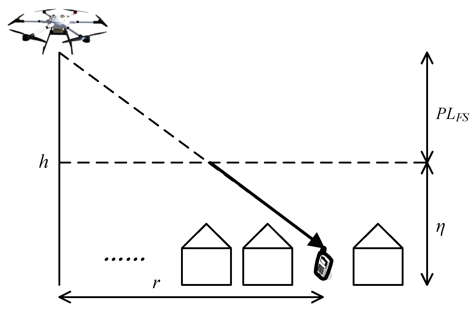
UAV communication platform belongs to low altitude platform (LAP), that is, the flight area is in low altitude airspace. The AtG communication occurs in accordance to two main propagation groups according to whether strictly meet the LoS conditions, while the non-line-of-sight (NLoS) conditions corresponds to receivers with no UAV platform LoS but still receiving coverage via strong reflections and diffractions [10,11]. The AtG communication channel from the UAV platform to the GTs is mainly dominated by LoS links. Radio signals emitted by the UAV platform base station propagate in free space producing the free space path loss and reach the ground building incuring shadowing and scattering thus introducing additional loss in the AtG link referring to the excessive path loss as shown in Figure 2. Accordingly, the resulting path loss of the AtG communication (expressed in dB) can be modeled as:
P L ξ = P L F S + η ξ ,
where P L F S represents the path loss of free space between the UAV and ground users (GUs), and ξ refers to the propagation groups the propagation groups where classified according to the ground receiver strictly LoS and NLoS conditions, while ξ L o S , N L o S . Set the maximum allowable path loss threshold P L m a x , which corresponds to a circular coverage with radius r m a x . Noticing that the path loss between the UAV and any ground receiver within this circular coverage is less than or equal P L m a x . It is important to note that the value of P L m a x depends on the sensitivity of the receiver and the target communication quality of service. Assume that the isotropic transmitter and receiver antennas,the total path loss between the UAV platform and all ground receivers can be measured as the mean value of the path loss as the following:
P L = ξ P L ξ P ξ ,
where P ξ represents the probability of occurrence of a certain propagation group ξ , while P ξ = 1 , P L ξ = 20 log 4 π f d c + η ξ , d = h 2 + r 2 is the Link distance between the UAV LAP and GUs, h is the UAV LAP altitude, and r is the ground distance between the UAV platform and GUs.
In the urban environment, the probability of the geometric LoS between the ground transmitter at altitude h T X and the receiver at altitude h R X depends on three statistical parameters α β and γ related to the urban environment [10,11,12]. The probability P L o S , n that the height of an obstruction building is smaller than height h L o S , n is given by:
P L o S , n = 1 e x p h L o S , n 2 2 γ 2 ,
where h L o S , n is the height of a building that would obstruct the LoS in meters, while h L o S , n = h T X n + 1 2 h T X h R X N n , N n is the number of buildings crossed by the LoS, while N n = f l o o r r α β . The parameter α is the ratio of land area covered by buildings to total land area (dimensionless).The parameter β is the mean number of buildings per unit area (buildings/km2), r = h / t a n ( θ ) , while θ is elevation angle. The parameter γ is a variable determining the obstruction building height distribution, which defined by the Rayleigh probability density function(PDF)of the height h L o S , n , namely f x = x γ 2 e x p x 2 2 γ 2 .
The probability P L o S having LoS rays at position r r m a x for GUs is given by:
P L o S = 0 N n 1 P L o S , n ,
The equation (4) can be considered as a continuous function of elevation angle and the three environment parameters and can be used for any h T X and h R X heights. In the UAV air base station platform case we can disregard h R X since it is much lower than the UAV platform altitude. However, the series in equation (4) cannot be further reduced, so it is necessary to simplify the calculation of LoS probability. Note that the trend of LoS probability can be closely approximated to a modified Sigmoid (S-shape) function having the following form:
P L o S θ = 1 1 + a e x p b θ a ,
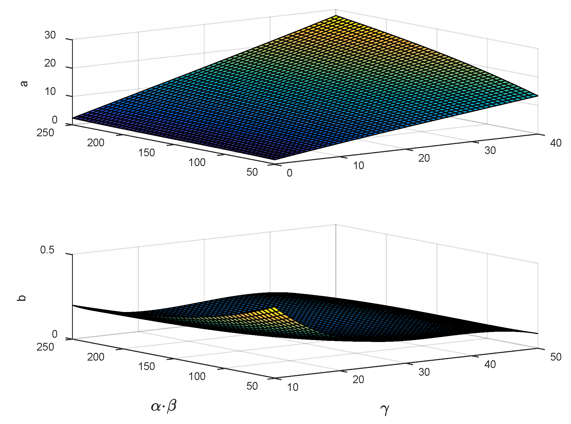
where a = j = 0 3 i = 0 3 j A i j α β i γ j and b = j = 0 3 i = 0 3 j B i j α β i γ j are the fitting parameter, while A i j and B i j are the polynomial coefficients. In order to link the fitting parameters with environmental parameters, surface fitting using two variables ( α × β ) and ( γ ), as shown in Figure 3.
Substituting from equations (5) into equation (2) to get:
P L = η L o S η N L o S 1 + a e x p b θ a + 20 log 4 π f d c + η N L o S ,
where f is the carrier frequency, c is the speed of light.

2.2. Modeling UAV Communication System

In this paper, we study a multi-hop communication system of tethered multi-rotor UAV low altitude emergency communication platform, where the UAV acts as the air MBSs and MRs and M 1 UAVs are deployed in a given geographical area within a given limited duration T to serve collaboratively a group of K > 1 Gus at altitude h. Each UAV is equipped with a micro base station to provide communication coverage for GUs within the circle of the maximum coverage radius r m a x in Figure 1, where the radius of GUs in polar coordinates is r G and the angle is α G . If the UAV is static, it hovers over the center of the circular coverage area; if the UAV is mobile, it circles over the circular coverage area with radius r U and angle α U , and flies in one direction at its maximum speed V. The multi UAV collaborative communication system equipped with dual antennas adopts a 2.4GHz microwave communication frequency band and space-time block coding (STBC). Assuming using M -base modulation, each m bits first in the binary information bit stream transmitted by the information source are divided into a group, and two consecutive sets of bits are modulated and mapped, that is, each set of bits is mapped to a modulating symbol on the constellation diagram. Therefore, we obtain two modulation signals x 1 and x 2 , and encoding method as the following:
X = x 1 x 2 x 2 * x 1 * ,
where X is the encoding matrix and x 1 * represents the complex conjugate of x 1 .
UAVs and GUs constitute a multi-source multi-destination multi-hop relaying, as shown in Figure 1, where assuming that GUi as the source node or the destination node, GUj acts as the destination node or source node according to the communication direction, while the UAVm and UAVm+1 act as relays in both directions, and the center of the circular coverage area of UAVm is the origin of the coordinate system. The coordinates for the GUi and GUj are ( r i cos α i , r i sin α i ,   0 ) and ( D + r j cos α j ,   r j sin α j ,   0 ) respectively. For static UAV, the coordinates for the UAVm and UAVm+1 are ( 0 ,   0 , h m ) and ( D ,   0 ,   h m + 1 ) respectively. For mobile UAV, the coordinates for the UAVm and UAVm+1 are ( r m cos α m , r m sin α m ,   h m ) and ( D + r m + 1 cos α m + 1 , r m + 1 sin α m + 1 ,   h m + 1 ) respectively, where α m and α m + 1 is the angle between the UAV and the X axis. Using CC, UAVmdemodulates and decodes the information sent by GUi, then encodes the channel and forwards it to the UAVm+1. UAVm+1 demodulates and decodes the received information, then encodes the channel and then forwards it to GUj. The communication link signal-to-noise ratio (SNR) is as follows:
γ n = P T X g n 2 σ 2 Q n ,
where g n is the channel fading coefficient, σ 2 is the noise variance, and the power loss Q n satisfies P L n = 10 log 10 Q n , while n 1,2 , 3 , 𝑛=1, 𝑛=2, and 𝑛=3 correspond to the uplink, AtA, and downlink conditions, respectively. Assuming that the AtG communication links are Nakagami-k fading channels, k [ 0.5,1 ) , the PDF of g n as the following:
f g n x = 2 k n k n x 2 k n 1 Γ k n Ω n k n e k n x 2 Ω n ,
where x 0 , Γ ( · ) is the Gamma function, k n is the shape parameter of Nakagami fading and indicates the severity of fading, Ω n = E g n 2 is the average fading powers. Using (8) and (9), the PDF of γ n obeying gamma distribution are as follows:
f x y n , z n = x y n 1 e x z n z n y n Γ y n ,
where y n is shape parameter, z n is scale parameter. The cumulative distribution function (CDF) of γ n can be derived as:
F γ n x = Γ x z n , y n ,
where Γ ( · ,   · ) is the incomplete Gamma function. By averaging instantaneous BER of the joint PDF of the link SNR γ 1 , γ 2 and γ 3 , the total BER can be obtained as:
P e = H z 1 ,   y 1 + H z 2 ,   y 2 + H z 3 ,   y 3 2 H z 1 ,   y 1 H z 2 ,   y 2 2 H z 1 ,   y 1 H z 3 ,   y 3 2 H z 2 ,   y 2 H z 3 ,   y 3
where H ( z n , y n ) = 1 2 1 2 z n 1 + z n N = 0 y n 1 2 N N 4 1 + z 1 N , while y n = k n and z n = Ω n 2 σ 2 k n Q n .

2.3. Optimization Problem Formulation

In UVA assisted multi-hop communication systems without reliable direct communication links, there is no need for a reliable direct communication link. In order to obtain the maximum system reliability, the goal is to minimize the total BER by jointly optimizing the height H, elevation θ transmission power P and path loss PL, and subject to the maximum allowable path loss constraints, transmission power allocation constraints, UAV height and elevation constraints. At the same time maximize the coverage radius and minimize the total path loss.
m i n H , θ , P , P L   P e ,
s . t . 0 P G P m a x ,   0 P U P m a x ,
P L n P L m a x ,   n 1,2 , 3 ,
r = h t a n θ r m a x P L m a x ,
θ m i n θ θ m a x ,   H m i n H H m a x
where (13a) are power constraints, (13b) are maximum allowable path loss constraint, and (13c)–(13d) are UAV height and elevation constraints.

3. Joint Optimization

Equation (13) shows that the joint optimization problem (13) is nonconvex with respect to (H, θ, P, PL). In order to deal with it more effectively, a joint optimization algorithm is proposed. Algorithm 1 illustrates the algorithm. This problem is solved by alternating minimization, in which the joint optimization problem (13) is decoupled into two subproblems, namely, the height and elevation subproblem with given power and path loss, and the power and path loss subproblem with given height and elevation. It is solved by gradient descent method and interior point method. In each iteration, the optimization variables are updated effectively by giving the last iteration, and the convergence of the algorithm is guaranteed.

3.1. Height and Elevation Optimization Subproblem

Given the power variables P G and P U , and the path loss variable P L , the equation (13) can be expressed as:
m i n H , θ P e ,
s . t . r = h / t a n ( θ ) r m a x P L m a x ,
θ m i n θ θ m a x ,   H m i n H H m a x
This is a convex optimization problem, which can be solved by standard convex optimization techniques. In order to achieve the local minimum BER, the descent direction is P o u t , set the step size of the gradient descent process to υ until the stop condition is met. A minimum BER threshold is also set δ , δ 0 . When P o u t t δ , the minimum BER is considered to be reached. There are optimal height h and elevation θ , the corresponding BER is minimized, which can be obtained by searching [ h m i n , h m a x ] and [ θ m i n , θ m a x ] and satisfying P e h = 0 and P e θ = 0 .

3.2. Power and Path Loss Optimization Subproblem

Given height variable h and elevation variable θ , the equation (13) can be expressed as:
m i n P , P L P e ,
s . t . 0 P G P m a x ,   0 P U P m a x ,
P L n P L m a x ,   n 1,2 , 3 ,
The BER function in the equation (15) is convex with respect to P G and P U , which can be solved by standard convex optimization techniques. Therefore, the optimal power allocation is realized.

3.3. Joint Optimization Problem

As shown in Table 1, the key idea of the proposed algorithm is to alternately optimize the height and elevation subproblem and the power and path loss subproblem. In each iteration, the main complexity of the proposed algorithm lies in steps 4 and 6, which needs to solve a series of convex problems. In iteration l , let S l = t = 1 T P o u t t , when S l S l 1 ϵ , the joint optimization algorithm converges, where ϵ is a predefined error tolerance threshold.

4. Simulations and Discussions

In this section, simulations and analysis are is conducted. Set time slot T=1000, the maximum moving distance of UAV in each time slot is υ =0.1 m,   V =10 m/s, η L O S [0.1, 1.6] dB, η N L O S [21, 23] dB, α [0.1, 0.3], β [500, 750], γ [8, 15], a [0.1139, 0.4290], b [4.8800, 12.0810], Ω =25 mW, σ 2 =-96 dBm, γ t h =0 dB,   ϵ =-10-2, P m a x =26 dBm r m a x =4000 m, P L m a x =113dB, and δ =-10-2.
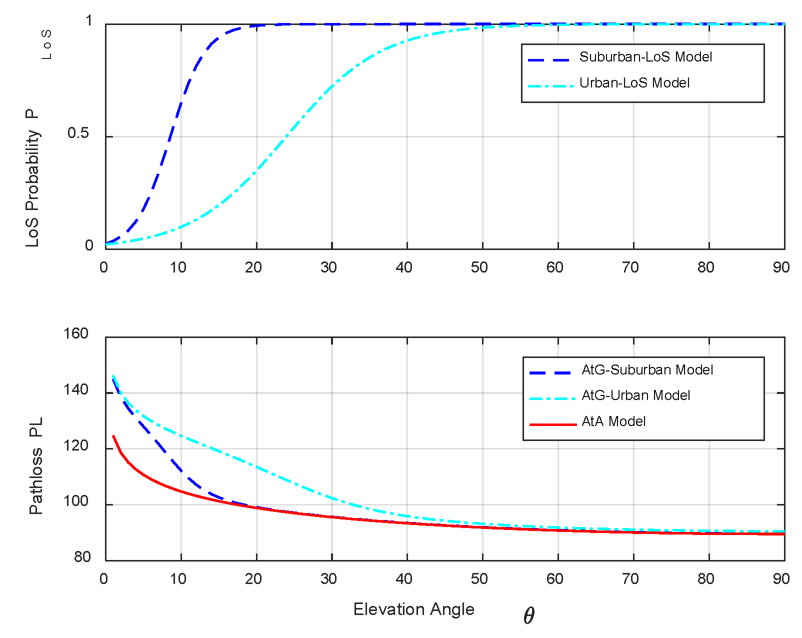
Figure 4 shows the Los probability and path loss under different environmental models. For the Suburban and Urban environment models, the LoS probability of Suburban environment increases rapidly than that of Urban environment and then tends to 1 with the increase of elevation angle, while the path loss of Suburban environment model decreases rapidly than that of Urban environment model and then tends to be stable in the AtG model, and the path loss attenuation of AtG model is faster than that of AtG model. That is to say, the AtA path loss is lower than the AtG path loss, and the AtG path loss in suburban environments is lower than that in urban environments. There is θ , the corresponding path loss is minimized. Within the maximum coverage radius, the closer the ground user is to the geometric center of the ground, the smaller the radius, the lower the path loss.
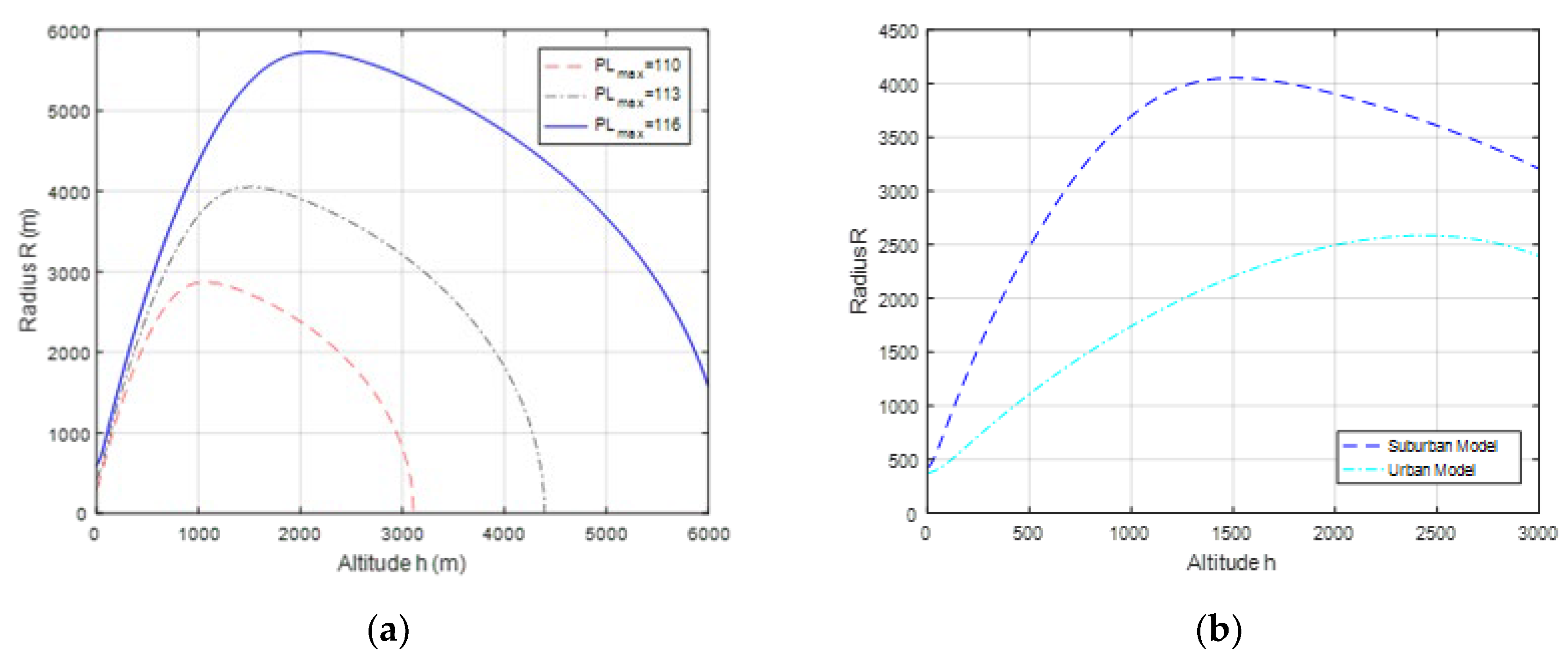
Figure 5 shows the effect of different P L m a x value and environments model on h . Figure 5 (a) shows the change of unit radius relative to UAV height in different P L m a x value. The point on the radius-height curve in the figure that changes its direction, namely the top of the curve is the optimal height solution h . It can be seen from Figure 5 (a) that the angle between the horizontal axis and the line generated by connecting the top of each radius-height curve to the origin represents the optimal elevation θ ,which always meets the constant ratio h r . The larger the P L m a x value, the larger the h value. Due to the main consideration of low-altitude airspace in this work, and notice that the LAP will be subject to physically constrained when reaching the optimal altitude. Therefore, there is an h , the corresponding path loss is the minimum. Figure 5 (b) shows the effect of suburban and urban environment model on h . It can be seen that h is a function of the maximum allowable path loss and environmental statistical parameters, which largely depends on the environmental conditions in specific regions.
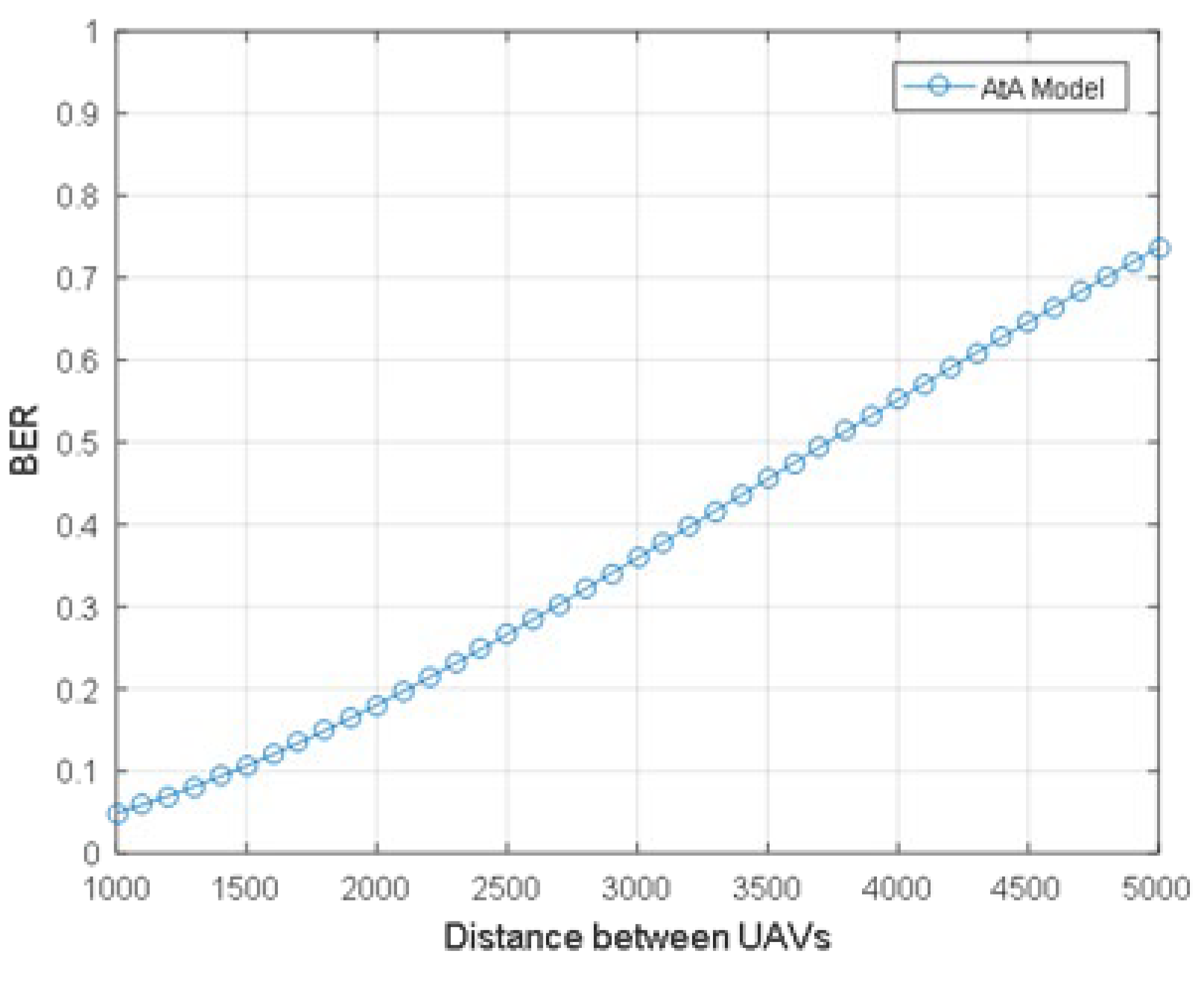
Figure 6 describes the relationship between the distance between UAVs and the BER of AtA communication links. When the distance between UAVs decreases, the BER decreases. That is to say, the shorter distance leads to lower outage, because when the distance decreases, the AtA communication link loss decreases.
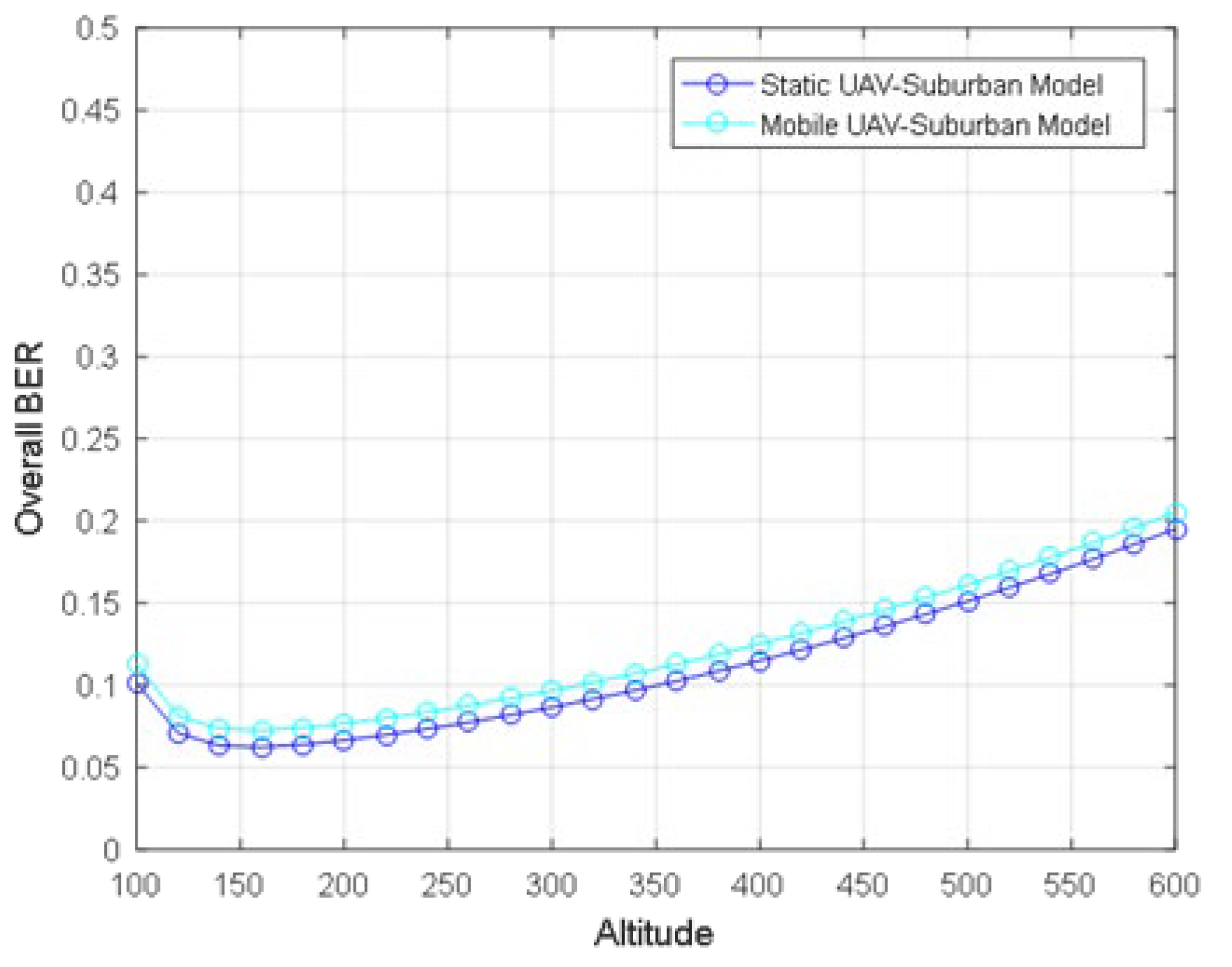
Figure 7 describes the BER of the downlink communication links of static and mobile UAVs under the suburban environment model. When the UAV height increases, the BER first decreases to the minimum value and then increases slowly. Because the AtG communication links loss decreases to the minimum value and then increases slowly with the increase of UAV height. The path loss of AtA communication link increase with the increase of UAV height, and its change is very small and the path loss difference is within 0.1 dB. It can be seen from Figure 7 that the BER of mobile UAV is slightly lower than that of static UAV. The bottom of the curve is h , corresponding to the minimum BER.
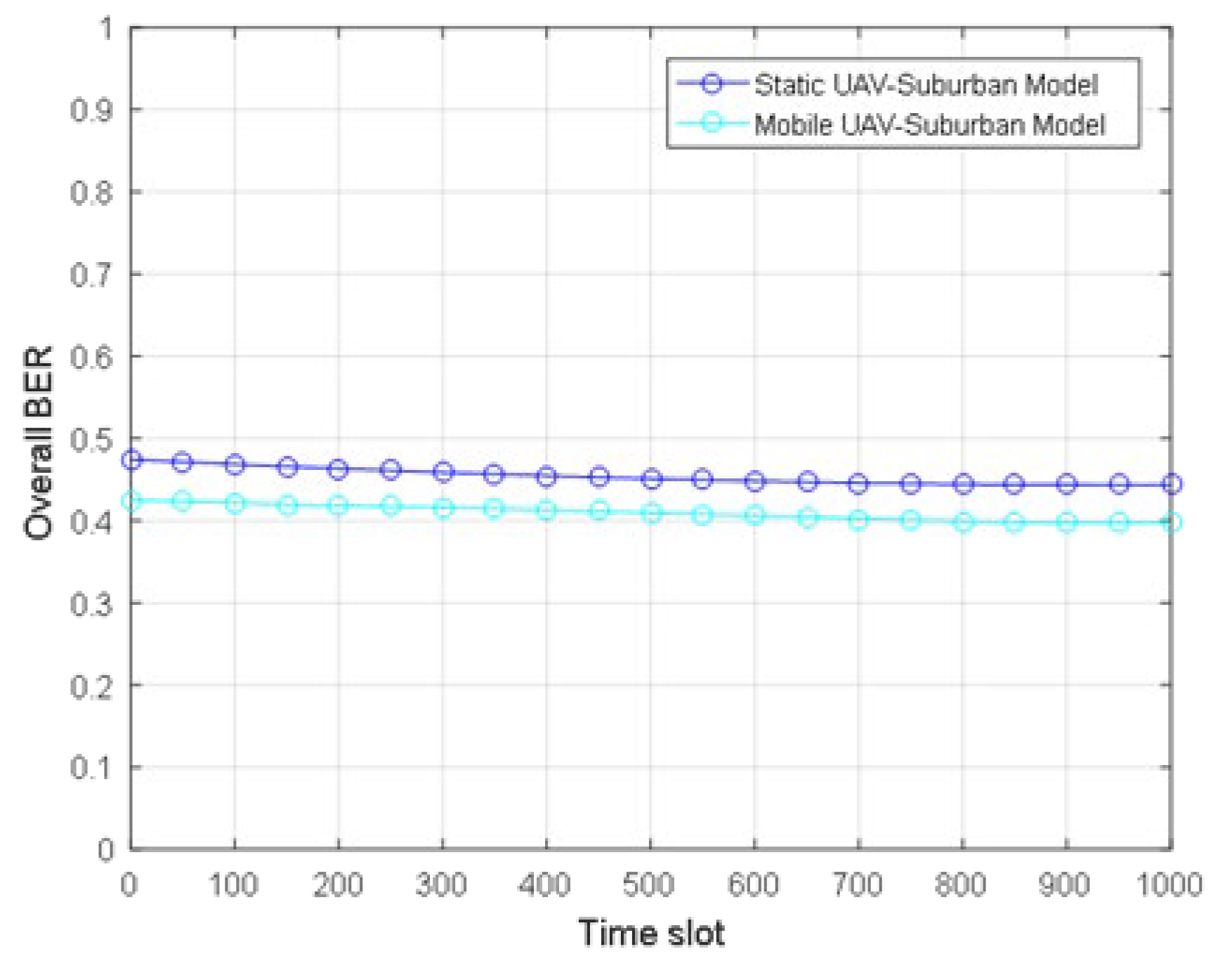
Figure 8 describes the total BER of static and mobile UAVs under the suburban environment model. Through the proposed joint optimization algorithm, the total BER decreases by about 5% with time, and the minimum BER is obtained, which tends to be stable at the minimum level. The results show that the total BER increases monotonously with the increase of the distance between GUs, and the total BER of mobile UAV is slightly lower than that of static UAV, while the difference between the minimum BER of static UAV and that of mobile UAV is about 8%. The results also show that using the mobility of UAV can improve the communication performance, and the performance of mobile UAV is better than that of static UAV. In addition, it can be seen from Figure 4, Figure 7 and Figure 8 that the optimal height of different reliability measures is different, namely the optimal height to minimize the total power loss is very different from the optimal height to minimize the total BER, and the optimal height to minimize the downlink BER and the total BER are also different.

5. Conclusion

This paper studies the problem of the maximum reliability of static and mobile UAVs in the multi-source, multi-destination and multi-hop communication model, in which UAV provides wireless services for remote users without direct communication link on the ground as a CC relay. The goal is to minimize the total BER by jointly optimizing the variable, and at the same time the total path loss is minimized and the ground communication coverage is maximized. Simulation results validated the superiority of the proposed joint optimization iteration algorithm and shows that the optimal height of different reliability measures is slightly different, and using the mobility of UAVs the outage performance of the mobile UAV is better than that of the static UAV and can improve the reliability of communication performance.

Author Contributions

Investigation: N.N. and Z.S.; methodology: N.N. and Z.S.; software, N.N.; writing—original draft: N.N.; writing—review and editing: Z.S., B.W. and L.X. All authors have read and agreed to the published version of the manuscript.

Funding

This research received no external funding.

Data Availability Statement

No available data.

Conflicts of Interest

The authors declare no conflicts of interest.

References

  1. Y. Zeng; R. Zhang; T. J. Lim. Wireless communications with unmanned aerial vehicles: opportunities and challenges. IEEE Commun. Mag. 2016, 54, 36–42. [Google Scholar] [CrossRef]
  2. M. Mozaffari; W. Saad; M. Bennis et al. A tutorial on UAVs for wireless networks: Applications, challenges, and open problems. IEEE Commun. Surveys & Tutorials 2019, 21, 2334–2360. [Google Scholar]
  3. B. Li; Z. Fei; Y. Zhang. UAV communications for 5G and beyond: Recent advances and future trends. IEEE Internet of Things J. 2019, 6, 2241–2263. [Google Scholar] [CrossRef]
  4. G. Geraci; A. Garcia-Rodriguez; M. M. Azari et al. What will the future of UAV cellular communications be? A flight from 5g to 6g. IEEE Commun. Surveys & Tutorials 2022, 24, 1304–1335. [Google Scholar]
  5. S. Ahmed; M. Z. Chowdhury; Y. M. Jang. Energy-Efficient UAV Relaying Communications to Serve Ground Nodes. IEEE Commun. Lett. 2020, 24, 849–852. [Google Scholar] [CrossRef]
  6. G. Zhang; X. Ou; M. Cui; Q. Wu et al. Cooperative UAV Enabled Relaying Systems: Joint Trajectory and Transmit Power Optimization. IEEE Trans. on Green Commun. & Networking 2022, 6, 543–557. [Google Scholar]
  7. N. Gupta; D. Mishra; S. Agarwal. Energy-Aware Trajectory Design for Outage Minimization in UAV-Assisted Communication Systems. IEEE Trans. on Green Commun. & Networking 2022, 6, 1751–1763. [Google Scholar]
  8. J. Dandapat; N. Gupta; S. Agarwal et al. Service Duration Maximization for Continuous Coverage in UAV-Assisted Communication System. IEEE Commun. Lett. 2022, 26, 2445–2449. [Google Scholar] [CrossRef]
  9. B. Li; S. Zhao; R. Zhang et al. Joint Transmit Power and Trajectory Optimization for Two-Way Multihop UAV Relaying Networks. IEEE Internet of Things J. 2022, 9, 24417–24428. [CrossRef]
  10. B. Al-Hourani; S. Kandeepan; S. Lardner. Optimal LAP altitude for maximum coverage. IEEE Wireless Commun. Lett. 2014, 3, 569–572. [Google Scholar]
  11. B. W. Khawaja; I. Guvenc; D. W. Matolak et al. A survey of air-to-ground propagation channel modeling for unmanned aerial vehicles. IEEE Commun. Surveys & Tutorials 2019, 21, 2361–2391.
  12. L. Xing; B. W. Johnson. Reliability Theory and Practice for Unmanned Aerial Vehicles. IEEE Internet of Things J. 2023, 10, 3548–3566.
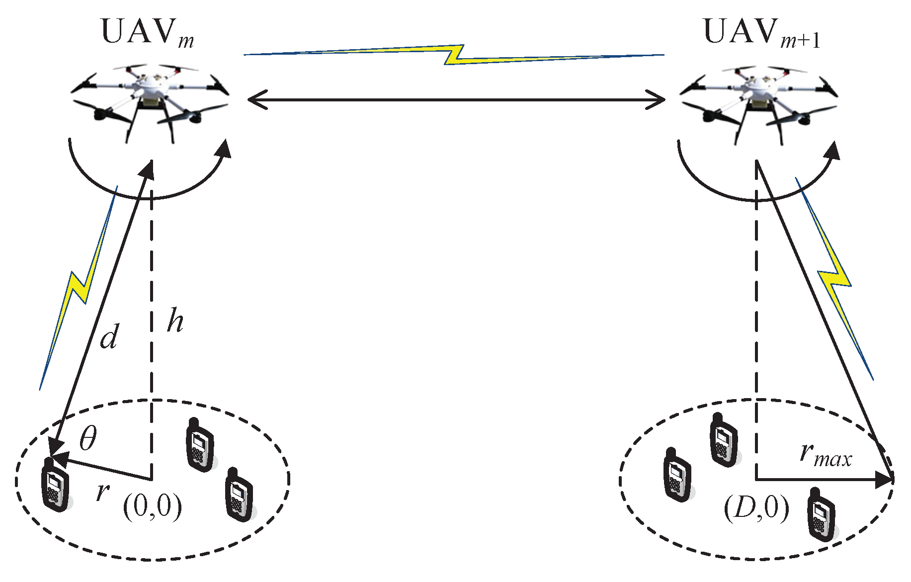
Figure 1. The considered UAV communication system.
Preprints 102817 g001
Figure 2. Radio propagation of UAV aerial base stations platform.
Preprints 102817 g002
Figure 3. 3D-fitting of the S-curve parameters and the environmental parameters.
Preprints 102817 g003
Figure 4. LoS probability and path loss for different environments model.
Preprints 102817 g004
Figure 5. The effect of different P L m a x value and environments model on h : (a) Radius vs. altitude curve for different P L m a x value; (b) Radius vs. altitude curve for different environments model.
Preprints 102817 g005
Figure 6. The BER for AtA communication model.
Preprints 102817 g006
Figure 7. The downlink BER of the static and mobile UAV for Suburban environment.
Preprints 102817 g007
Figure 8. Time slot vs. overall BER of the static and mobile UAV for Suburban environment.
Preprints 102817 g008
Table 1. Joint optimization algorithm for solving problem (13).
Algorithm 1
1:Initialize l = 0 , S 0 = 0 , P M t = P U t = P m a x , t = 1 , , T
2: Repeat
3:   l = l + 1 ;
4:  For t = 1 : T
5:    solve the height and elevation subproblem (14).
6:  For t = 1 : T
7:    solve the power and path loss subproblem (15).
8: Until S l S l 1 ϵ
Disclaimer/Publisher’s Note: The statements, opinions and data contained in all publications are solely those of the individual author(s) and contributor(s) and not of MDPI and/or the editor(s). MDPI and/or the editor(s) disclaim responsibility for any injury to people or property resulting from any ideas, methods, instructions or products referred to in the content.
Copyright: This open access article is published under a Creative Commons CC BY 4.0 license, which permit the free download, distribution, and reuse, provided that the author and preprint are cited in any reuse.
Prerpints.org logo

Preprints.org is a free preprint server supported by MDPI in Basel, Switzerland.

Subscribe

© 2024 MDPI (Basel, Switzerland) unless otherwise stated