1. Introduction
The medium-voltage DC (MVDC) technology has gained increasing interests in recent years, allowing enhancing power distribution capacity, improving operation flexibility and increasing power quality in distribution grid. Most renewable energy generations (REGs), and modern electronics loads (e.g. EVs) are DC. To integrate those elements into a DC distribution permit to avoid double conversions. In [
1], a state of the art of recent (up to 2019) research and applications of MVDC distribution systems in power grid, including planning and evaluation, main circuits, key equipment, control, and protection. Several papers have been published in the last three years. The integration of wind, photovoltaic and batteries in an islanded MVDC Network has been presented in [
2].
1.1. Prospects and Challenged in MVDC
One of the key-technology of MVDC is the solid-state transformer. This is a widely treated subject in the literature. The start-up and performance of an ST-based meshed hybrid microgrid connected to the main grid feeder through MVDC of a second ST are analysed in [
3] and [
4], while an SST based on three-level power module for interconnecting MVDC and LVDC distribution systems is discussed in [
5].
In analogous way, the use of multilevel converters in MVDC application has been also widely studied. In [
6] the modular multilevel DC transformer with wide voltage range regulation for DC distribution grid is presented. In [
7] and [
8] a multiport DC solid-state transformer based on MMC and cascaded H bridges approach for MVDC integration has been studied. A modular multilevel DC-DC converter with inherent bipolar operation for MVDC has been presented in [
9].
The problems of the protection of MVDC devices during faults is another large field of studies. In [
10] the authors present a hybrid modular solid-state transformer for UPS under short-circuit fault in MVDC. The problem of realizing a fault tolerant SST is presented in [
11], while in [
12] a hybrid DC circuit breaker for MVDC applications is described. In [
13], a DC fault ride-through method for MVDC distribution systems is presented. The problem of the partial discharge on the DC cables from an experimental point of view is studied in [
14], while a backup protection strategy for embedded MVDC links is presented in [
15].
1.2. System Level Modelling and Simulation
With the increasing complexity of the modern MVDC distribution grid, detailed simulation considering the actual behaviour of the power electronics switching devices can rapidly become a time consuming in terms of computation. To develop and evaluate suitable system level control strategies, a continuous time simulation approach can be useful to interact with the model with system-level grid controllers. This approach is not completely new. In [
16] the authors show how a continuous time simulation, combined with a distributed discrete event can enhance the flow of development to implementation of multi-agent-controlled power plants. In [
17] a continuos time distribution network simulator is used to investigate the integration of distributed energy resources into active distribution networks. The presented models in this work follow a state-space modelling approach as usually implemented in Real-Time Hardware in the Loop solutions, where active and passive components are modelled in Thevenin-Norton equivalencies as [
18] and [
19]. One innovative approach presented when compared with other averaging methods for modelling the DAB or SST such as in [
20] and [
21], is the modelling of passive components such as capacitors and inductors.
One of the goals of this paper is to present a way of modelling the power system elements for quick simulation and benchmarking of various configuration, especially aiming at MDVC grids. This is an extension of the preliminary work presented in [
22], to which the continuous time simulation aspect was added, allowing to interact with the parameters of the system while the simulation is running continuously.
Several contributions are added here, mainly based on the activities of students in Power Electronics at the University of Applied Sciences of Western Switzerland in Yverdon-les-Bains (HEIG VD), such as an MMC-AFE model and a continuous simulation interface. As one aim of this paper is also to supply an educational content, mainly on the use of the continuous time approach to the simulation of Power Systems. This is achieved with a detailed description of the various devices modelled in the MVDC.
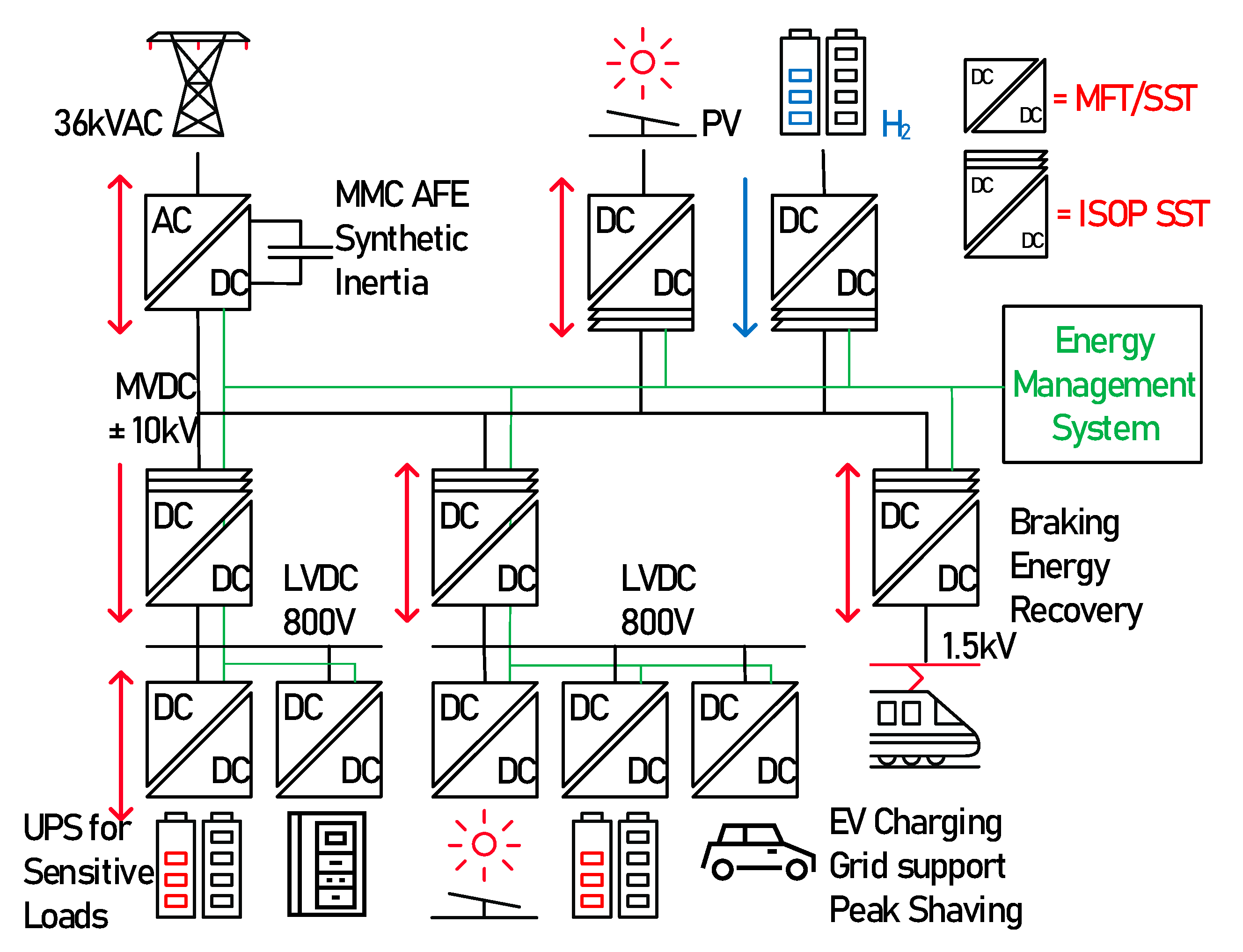
For illustration purpose, a full ±10kV MVDC power system has been modelled, with several LVDC interfaces as proposed in [
23]. The system is shown in
Figure 1. In this MVDC microgrid, most of the converter follow their own power set points, and the MMC based AFE ensures voltage stability by adjusting the power. Electrical balance is ensured within the limits of the AFE nominal power, and setpoint decisions from storage elements are taken by the Energy Management system. The model features bidirectional SSTs connecting loads, storage, sources, an SST in ISOP configuration connecting several LVDC grids for light EVs with local peak-shaving, another LVDC grid with local UPS for sensitive loads such as Data Centers, and finally an MMC-AFE connecting the MVAC network. As the scope of this work, the authors decided to focus on the DC side of the Active front End. All aspects related to AC transformer and phase unbalances will be considered in a future work.
The key innovation of this work lies in the use of high-level simulation model that may be run continuously with the possible action by the user, or a Python script that has the potential of adding AI related controllers. This tool is simple to implement also by students and can be run on any computer as it is not CPU demanding. This allows simple benchmarking of power systems and validation of any high-level system controllers.
This paper is arranged as follows. After an introductory section, the voltage and current source system level models are presented in section 2, modular arrangements in section 3.
Section 4 is devoted to the simulation of the full MVDC system, while section 5 presents the conclusions and the perspectives of system modelling technique applied to modern MVDC systems.
2. Voltage/Current Source System Level Models
Any power system can be described with its elementary Thevenin-Norton equivalencies, meaning as an arrangement equivalent controlled voltage sources and controlled current sources [
24]. Those sources implement an average behaviour of power converters or power sources and can be combined with the condition that some elementary rules are followed. The most important rule is that two voltage sources can’t be connected in parallel, and current sources can’t be connected in series, as from Thevenin’s laws. A capacitor typically behaves as a controlled voltage source which value is subject to the difference in currents it sees, while an inductor typically behaves as a controlled current source which value is subject to the difference in voltage it sees. Their voltage/current value results from the integration in time of the applied current/voltage respectively. The controls of those sources are then reflected on the behavior of the modelled elements.
The implemented MMC, SST and microgrid models with their current and voltage source equivalents could be run within any power electronics and systems simulation environment. To this specific work, the models have been run with simulation environment Simba.io by Aesim [
25]. This environment is a Python based implementation and features a specific Python API. This API allows building and calling models from Python scripts and programs. In this way all sort of implementation, optimization, pseudo real time operation, and complex post processing with tools that are not available with other simulation environments can be achieved.
2.1. SST Elementary Cell
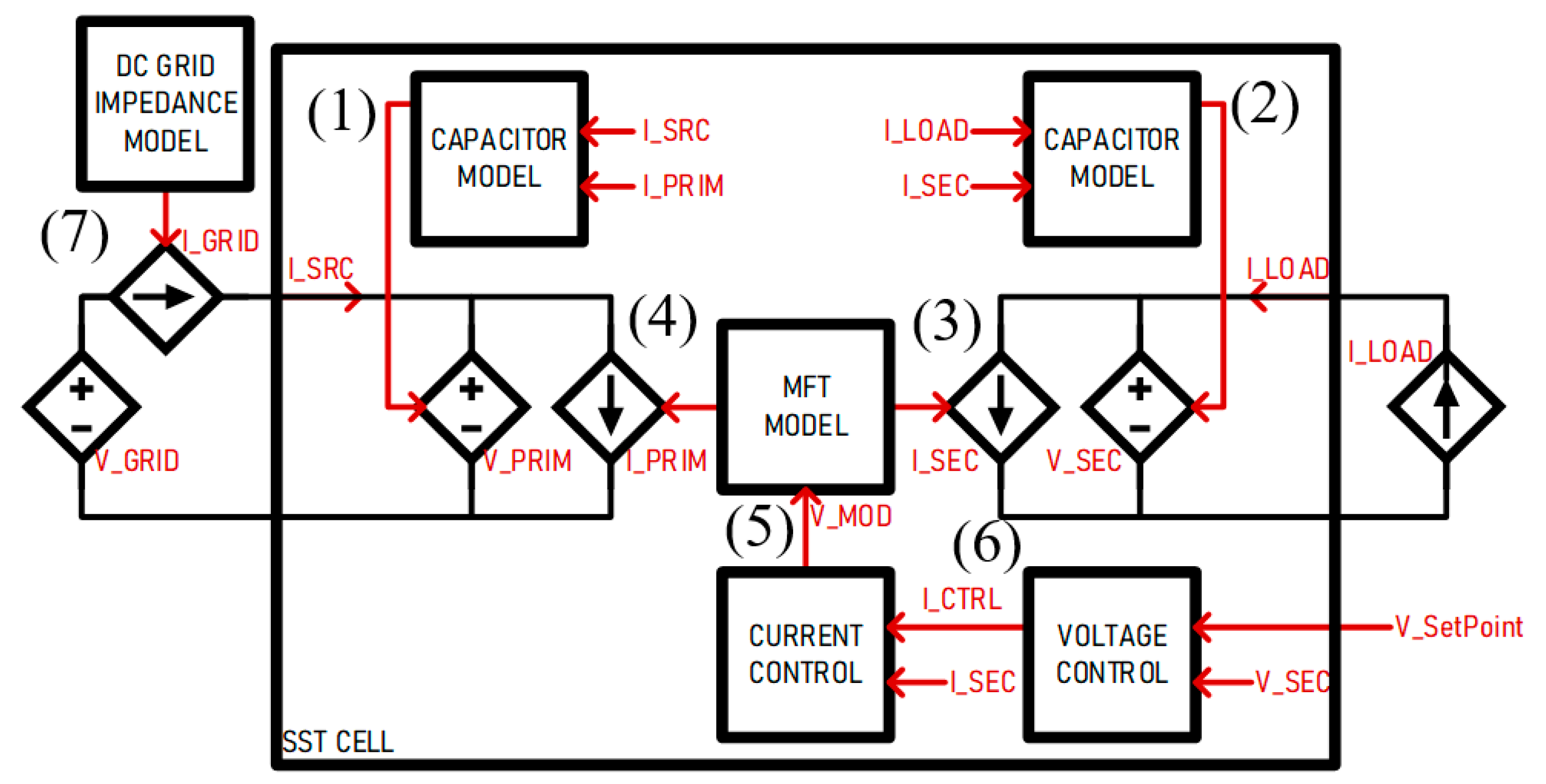
The SST cell is modelled with its equivalent current/voltage source model and can interface power systems that are also modelled as such. Both DC links on each side of the SST are interfaced with controlled voltage sources. The MFT windings are modelled with two controlled current sources which implement the physical aspects of an inductor. The functions performed by the SST cell are depicted in
Figure 2.
As a convention adopted in this work, the SST is connected to a DC grid on its primary side and a current source load on its secondary side. The dynamics of the system are reflected in the various time constants of the system elements. The behavior of the capacitors on each side of the SST is modelled as a current integrator multiplied by the capacitance value CDC, as described in Equation (1) and (2). The modulator has a time constant delay defined as a function of the switching frequency fSW. The current in the MFT inductance LMFT is modelled as an equivalent transfer function taking the applied voltage VMOD input as in (3) and (4).
The voltage/current cascaded PI controllers described by (5) and (6) are tuned and optimized as a function of the model’s physical parameters.
The voltage controller maintains the secondary side voltage to a given setpoint, providing a current setpoint. The current controller maintains de MFT current to the given set points by providing the modulation voltage V
MOD. The DC Grid Strength is modelled through its "equivalent impedance" represented by its resistive and inductive components R
GRID and L
GRID as in (7). The current source representing the grid impedance interfaces the DC ideal grid voltage source V
DC with the primary side of the SST. The parameters used for running the model are described in
Table 1.
The model is run at simulation time step t
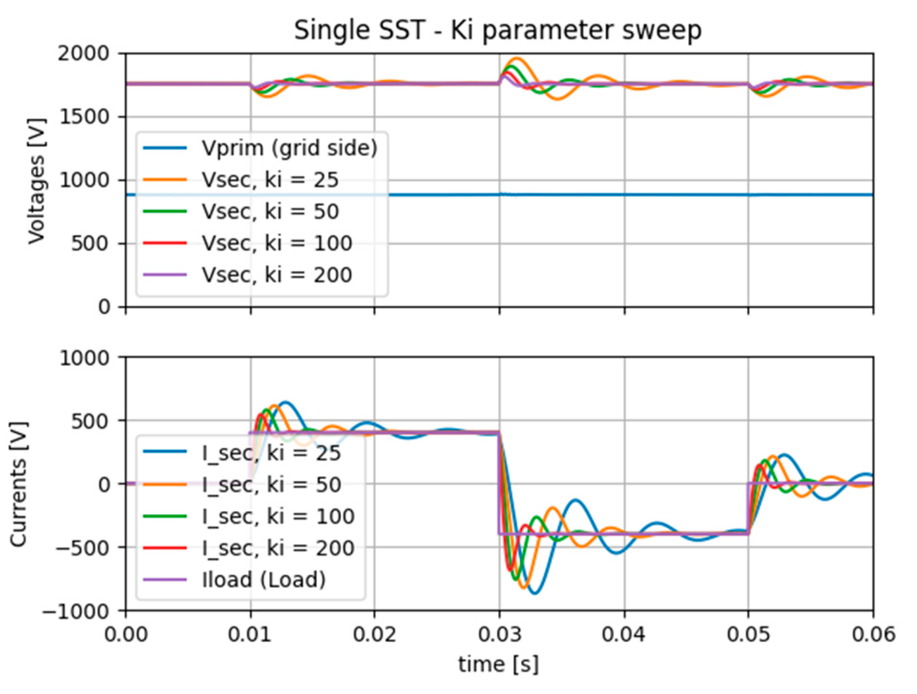
s=1µs, with current steps on the load side and a steady voltage on the grid side. A parameter sweep is performed on the PI controllers to assess its effect on the dynamics.
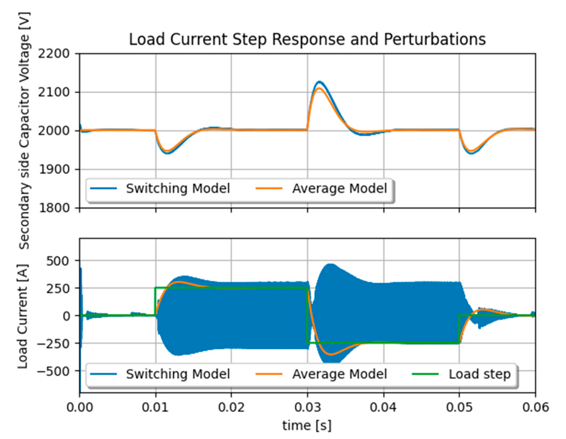
Figure 3 shows that the dynamics of the SST cell model correspond to a fair extend to a real DAB based SST converter. When compared to real hardware results from built SST demonstrator as in [
26] the voltage controller’s time responses correspond well enough to perform system level studies. Another comparison is made between switching model and average model as in
Figure 4, showing the dynamic accuracy and strong gain in computation time, as measured between a detailed switching model and the average model, at the same simulation pace. A ratio of about 20 was measured in simulation speed, namely few seconds against almost a minute for one single SST.
2.2. SST Cell Connecting a Battery and an AFE through a PCC
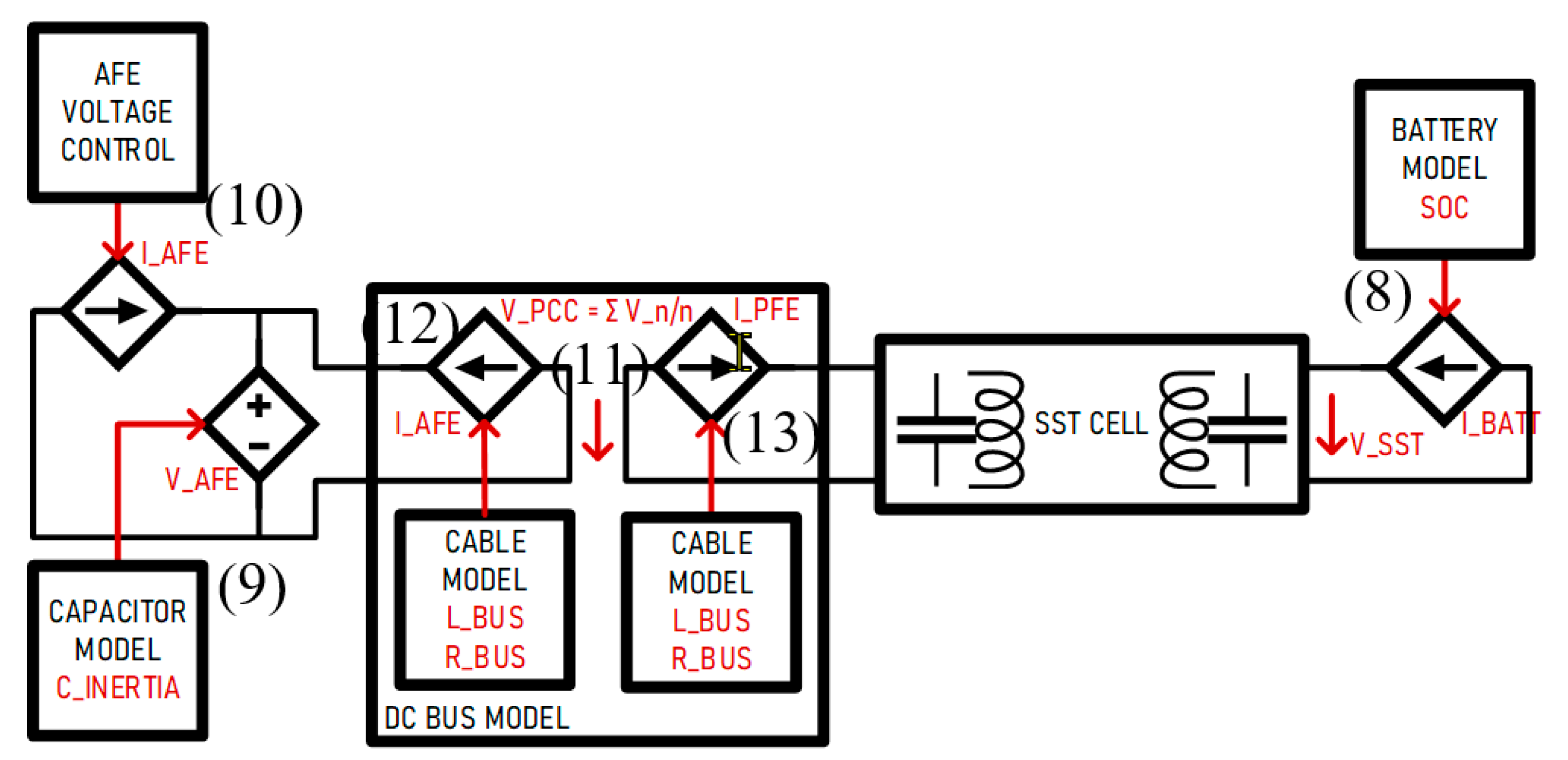
The same SST Cell as described previously is run with a model of an Active Front End (AFE) on the primary side, and a model of a Battery on the secondary side. As illustrated in
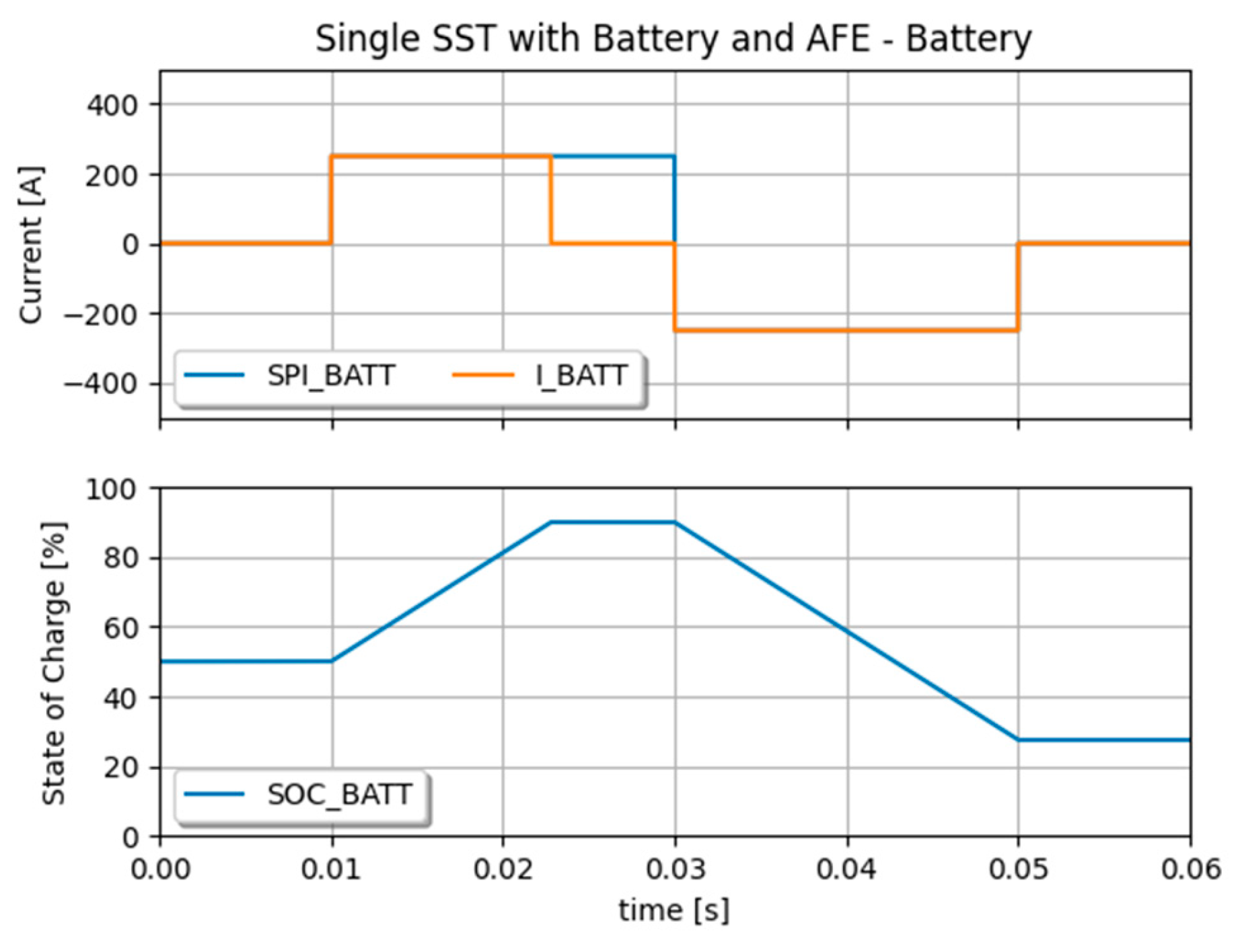
Figure 5, a DC bus model is implemented for connecting the two voltage sources, from the AFE and the SST primary side. The DC bus model considers the AFE side as the side providing voltage, and the Passive Front-End side (PFE) as the side only drawing current. The Battery is a simple controlled current source; however, it produces current only when its State of Charge (SoC) permits it. SoC should typically vary between 10% and 90% to maintain optimal battery lifetime, it is calculated as a function of the integral of the battery current I
BATT and the battery capacity Q
BATT as given in (8).
The AFE is modelled as a controlled current source IFEED connected to a controlled voltage source VAFE.
Equation (9) implements the behaviour of a capacitor model CAFE which value represents the inertia of the grid.
The AFE current is controlled in a way to maintain the AFE voltage to the voltage set point given by VDC with the use of a PI controller as given in (10). It features given dynamics, inertia and current limitation set by the system.
The DC Bus is connecting voltage sources and must be consequently modelled as current sources. The controls of those current sources implement the dynamic response of a cable with its resistance R
DCBUS and line inductance L
DCBUS. In this case, cables are sufficiently short no to consider its capacitive component as one would do in DC transmission lines. This aspect will be subject of a future work as its capacitive component has to be modelled as an equivalent voltage source, whose value get’s significant impact when far from the SST capacitors. The model features the voltage of the Point of Common Coupling (PCC), and current sharing between the connected devices. The voltage of the PCC is given by (11), the currents I
AFE and I
PFE on both sides of the PCC are given by (12) and (13).
Figure 6 shows results of the model run with a load profile reflected by a current set point given to the Battery system. When SoC reaches 90%, the Battery current falls to zero even though the setpoint is set to its nominal value. As illustrated in
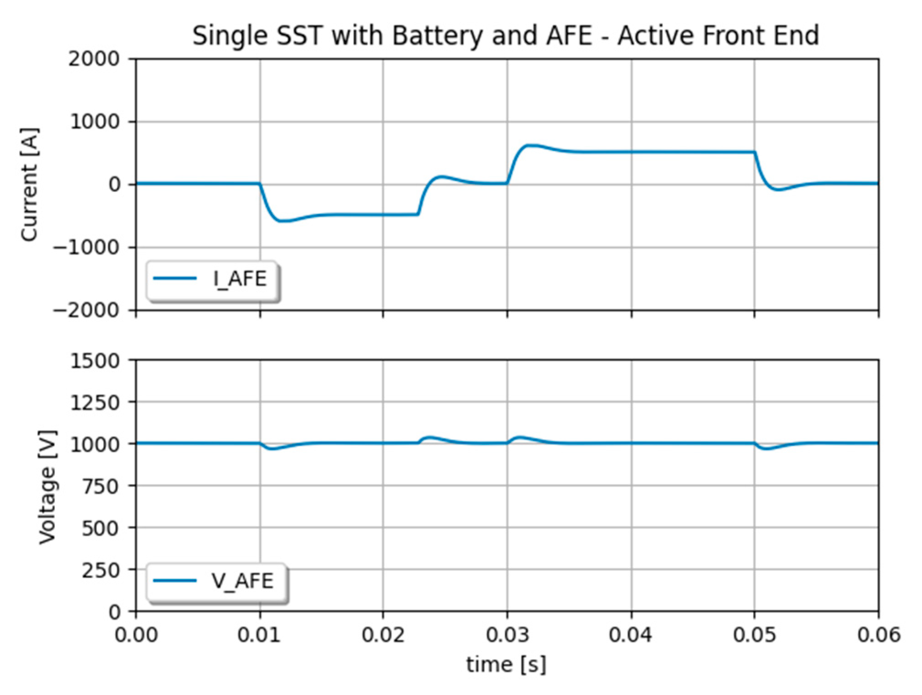
Figure 7, the AFE is maintaining the DC bus voltage with a “Synthetic Inertia” that is defined by its capacitor model and voltage controller.
2.3. Considerations on Modelling MMC and AC Connection
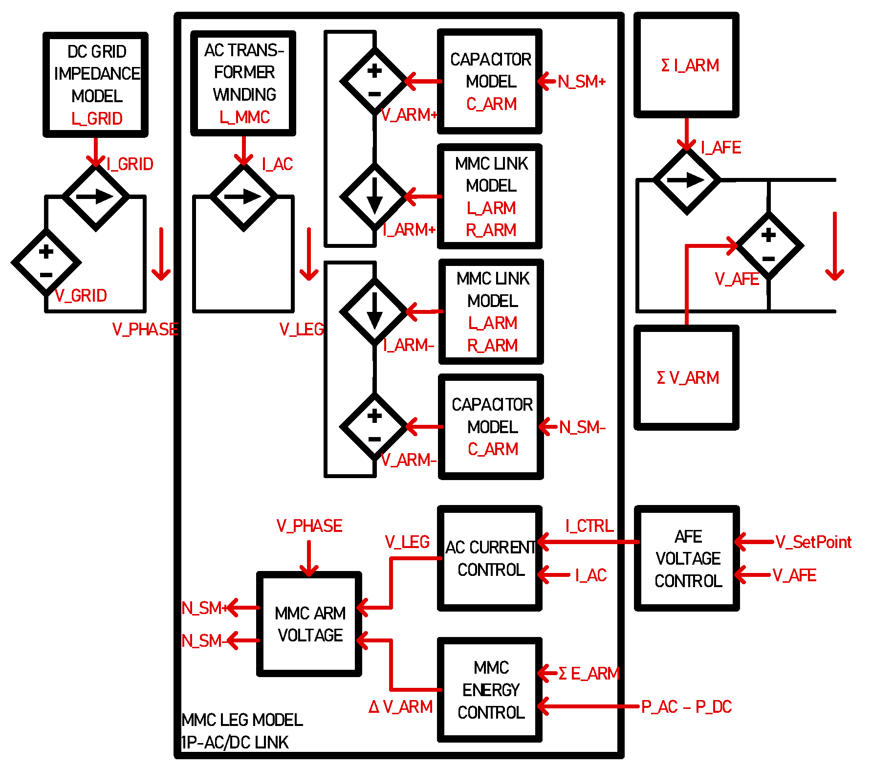
The MMC block is modelled in a way it can interface an AC port with a DC port. The AC port can be a three-phase grid transformer or an MFT connecting another MMC leg for connecting another DC grid. Each leg is running independently, connecting at the AC or DC port only. The MMC arms have capacitors, and their stored energy can be controlled [
27]. When there is a power difference between the AC port and the DC port, the capacitors get charged or discharged providing a so-called Synthetic Inertia.
As illustrated in
Figure 8, the MMC arm is modelled as a voltage source, that implements the insertion and bypass of capacitors, in series with a current source, which implements the behaviours of the series connected filter inductors. The AFE voltage controller and the energy controller both give set points of the sum and difference of arm voltages so they can provide two functions at a time, supply the DC grid voltage, and maintain the stored energy to desired levels. On the AC side, the phases of the MMC connect in a way that reflects the AC transformer configuration, namely star, delta or single phase. The capacitor’s effects on the waveforms are modelled in a way their charge is function of stored energy and arm current. A similar approach has been adopted in [
28] aiming a Real-Time implementation.
This work focusses solely on the DC grid related aspects and the impact of connecting numerous SSTs with symmetric and asymmetric loadings. All aspects related to AC grid side, namely transformer connection and phase unbalances together and MMC energy storage will be presented in a future work.
2.4. Discretization in the Simulation Model and Stability
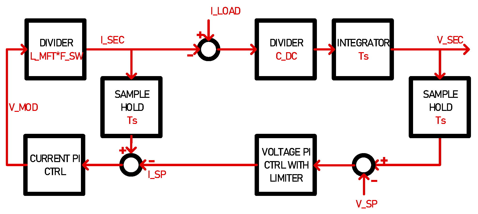
The equations given in this section are transposed in the simulator in terms of blocks, namely integrator, divider, sampler, and PI controller with or without limiter and anti-windup.
Figure 9 show an example for the computation of the secondary side capacitor voltage as seen at the SST port. The rest of the equations are implemented in the same fashion. In terms of stability of the system and convergence of the computations, the time constants of the system must remain higher that the simulation time step of 1µs. In other words, inductors, capacitors and controllers implemented in the system must be dimensioned accordingly.
3. Modelling of the Modular SST
The elementary SST cell described in section II.A can be vertically combined to generate modular configurations, such as Input-Parallel Output-Series (IPOS) and Input-Series Output-Parallel (ISOP) allowing to connect LVDC to MVDC grids. Each SST cell is working independently and is implemented with bypass capabilities for simulating the effect of a cell fault on the system.
3.1. Parallel Connection in Modular SST
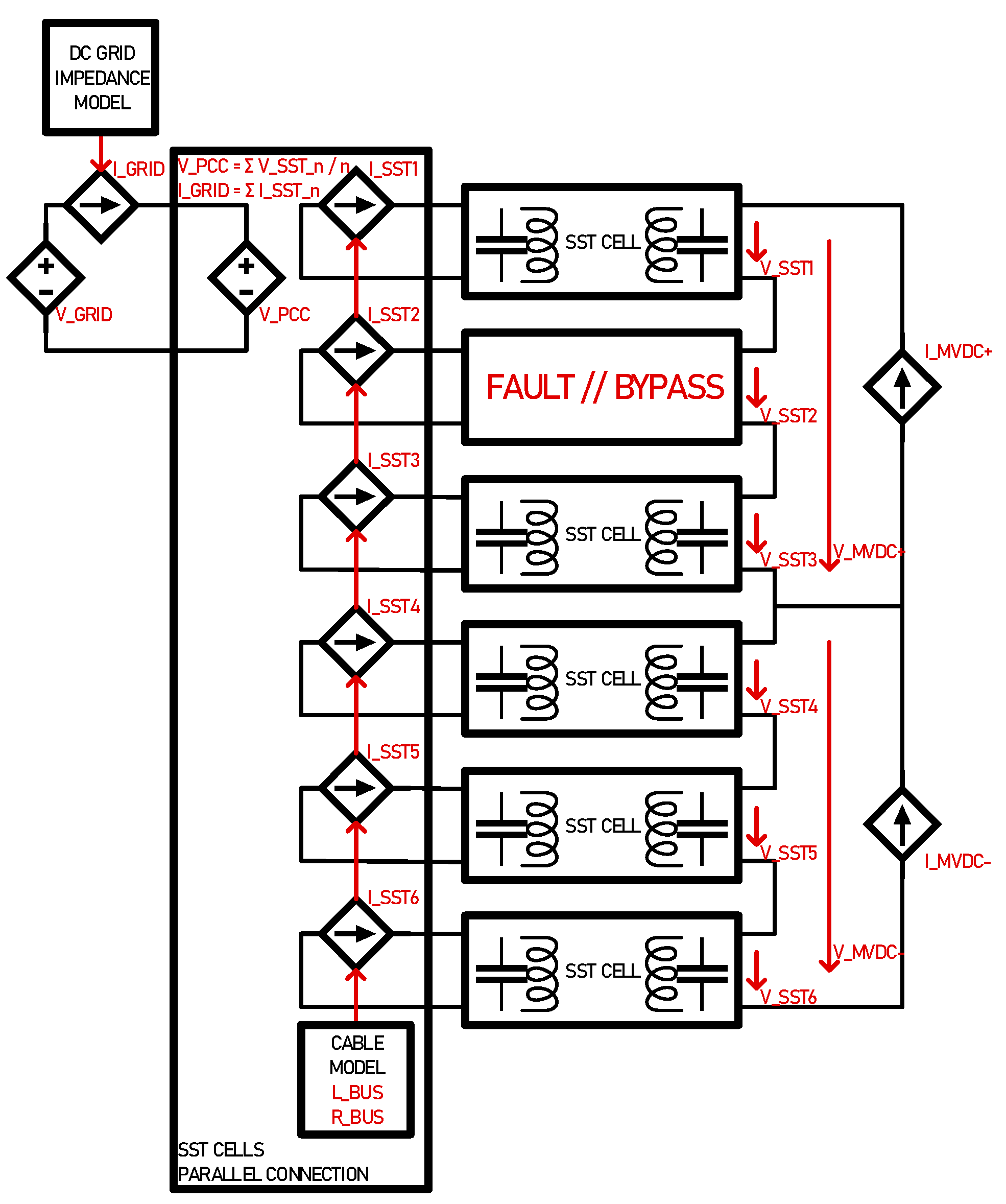
On the MVDC side, the series connection of voltage sources is not a problem. On the LVDC side however, the parallel connection of voltage sources cannot be done without specific attention on the SST local PCC side. Voltage sources must be connected through an arrangement of controlled current sources that reflect the dynamics due to cabling resistance RDCBUS and coupling inductors LDCBUS. This allows generating a PCC voltage that is equivalent to the mean value of all N primary side voltages of all N parallel connected SSTs as in (14), it also allows current sharing in between the cells, reflecting on what is drawn from the load side, as given in (15). The final current share in between the parallel connected modules is given by (16).
3.2. SST in IPOS Configuration with Faults
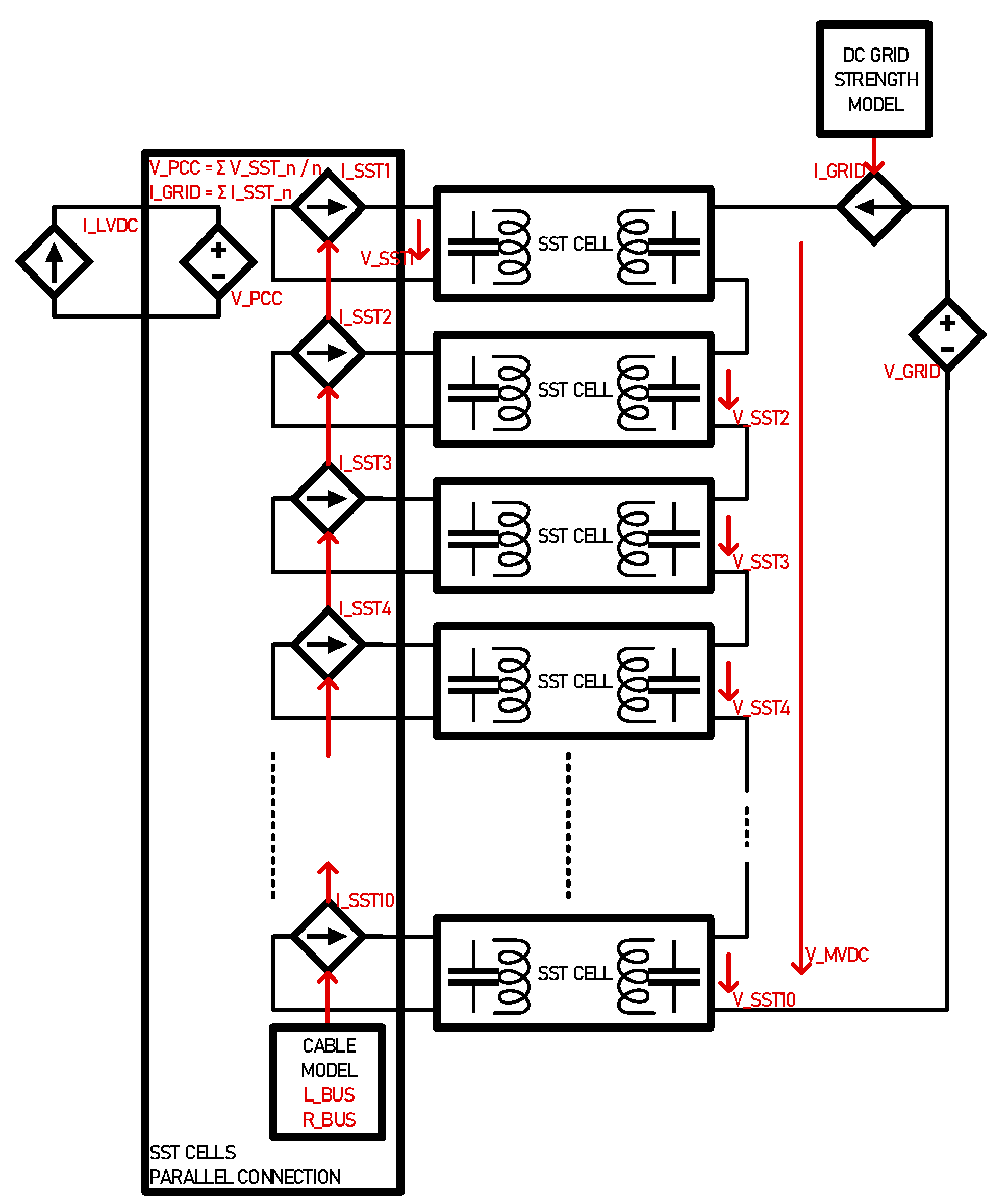
In the 6-cell IPOS configuration illustrated in
Figure 10 implements the equations given in (14)-(16).
The 3-port MVDC side voltage is fully controlled by the sum of individual SST cells. This arrangement allows asymmetric loading on the MVDC side with individual voltage control of both MVDC+ and MVDC- ports.
The system is run for demonstration with a fault occurring in one cell to assess voltage and current stability on MVDC side.
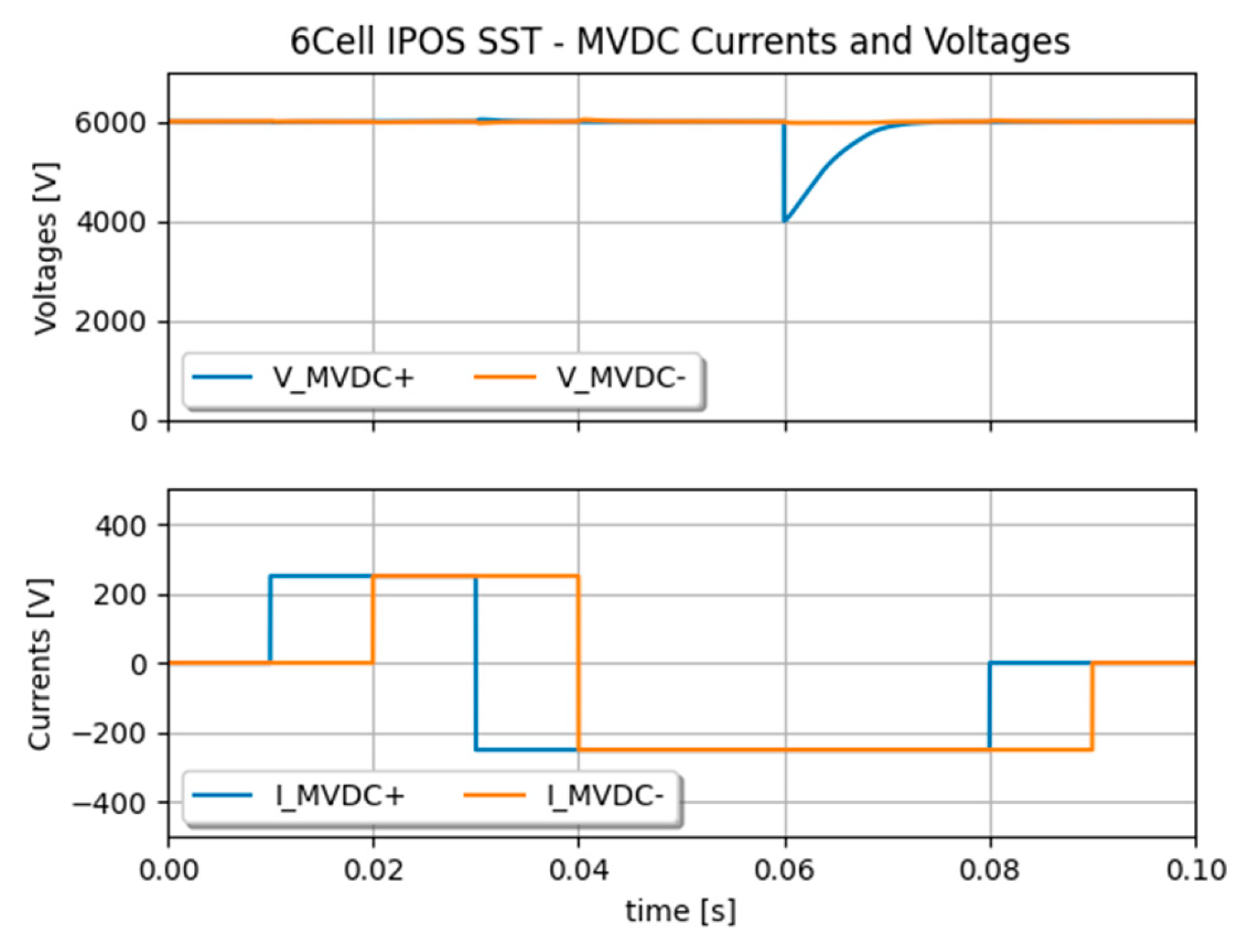
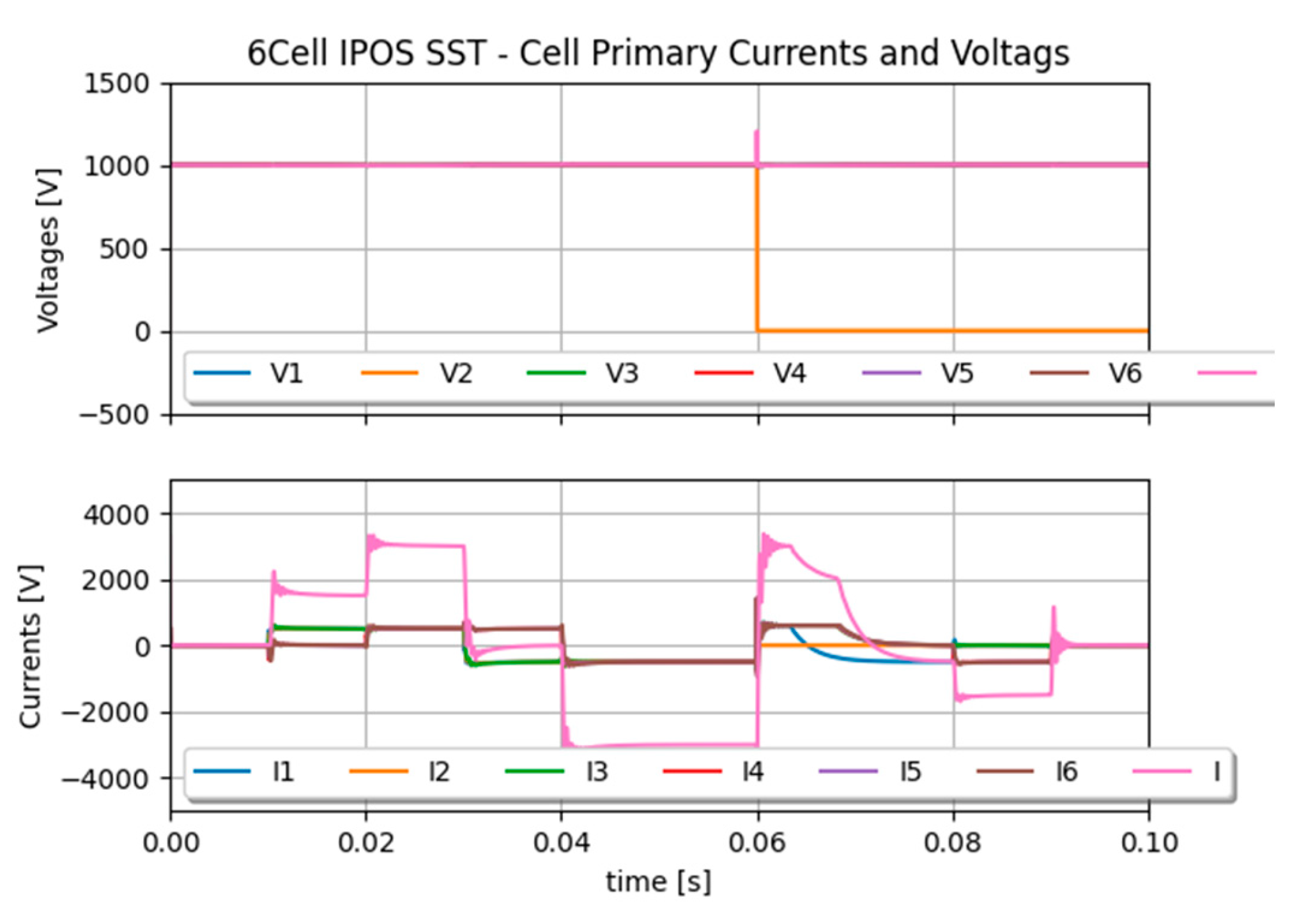
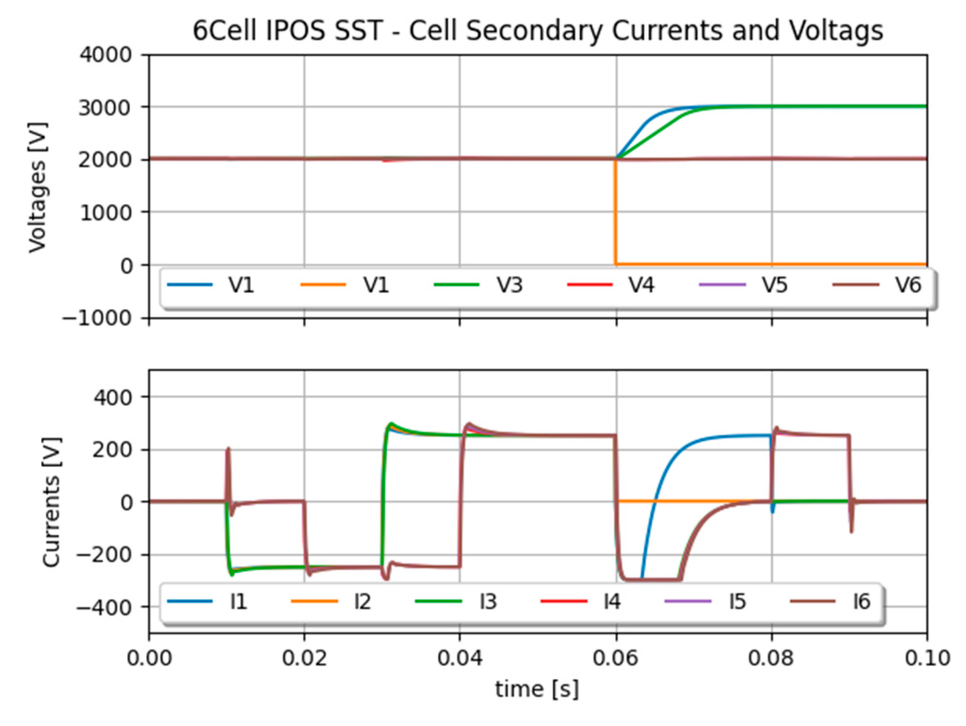
Figure 11 shows currents and voltages on the primary and secondary sides of the SST cells. Asymmetric currents are well distributed among the cells connected to the PCC. At some point, when the two MVDC side currents are opposite to each other, no current is taken from the LVDC grid side as current is only circulating in between the cell via the PCC. When a fault occurs, the MVDC+ voltage is maintained by two cells instead of three, as illustrated in
Figure 12 and
Figure 13. Their voltage setpoint is re-adjusted by control after the fault occurrence. These results show the accuracy of the SST local PCC model for the parallel connection of individual SST cells.
3.3. SST in ISOP Configuration
The ISOP is slightly different from IPOS in the sense that MVDC side is given by the system and that LVDC side must be controlled. In the arrangement presented by
Figure 14, the LVDC side voltage is controlled by one SST cell, which provides a PCC for the full converter. All other cell voltages on the MVDC side are individually controlled, naturally providing voltage balancing in between the cells.
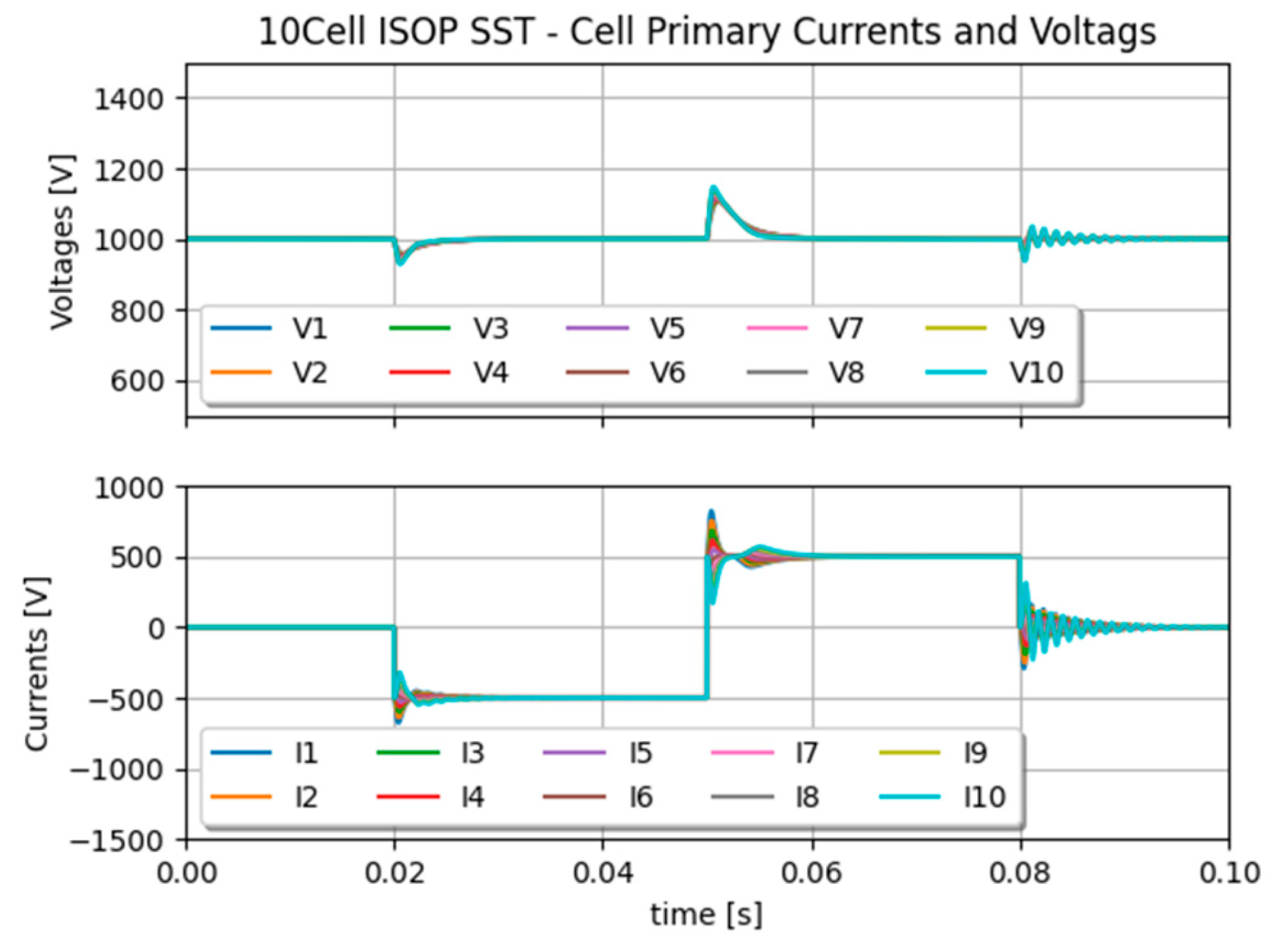
Results depicted in
Figure 15 show a slight voltage difference between the secondary side voltage of the SST cell that is controlling the LVDC side, because it takes the voltage difference between the MVDC and the sum of all secondary side cell voltages. Otherwise, we foresee excellent voltage and current balancing for this kind of arrangement.
4. Simulation of the Full MVDC System
The previously presented models can be put together for building a complex MVCD system. The presented way of modelling is quite independent from the simulation environment; in this case it has been implemented with Simba.io because of the Python API interface it features.
4.1. Full Power System Model
The power system in
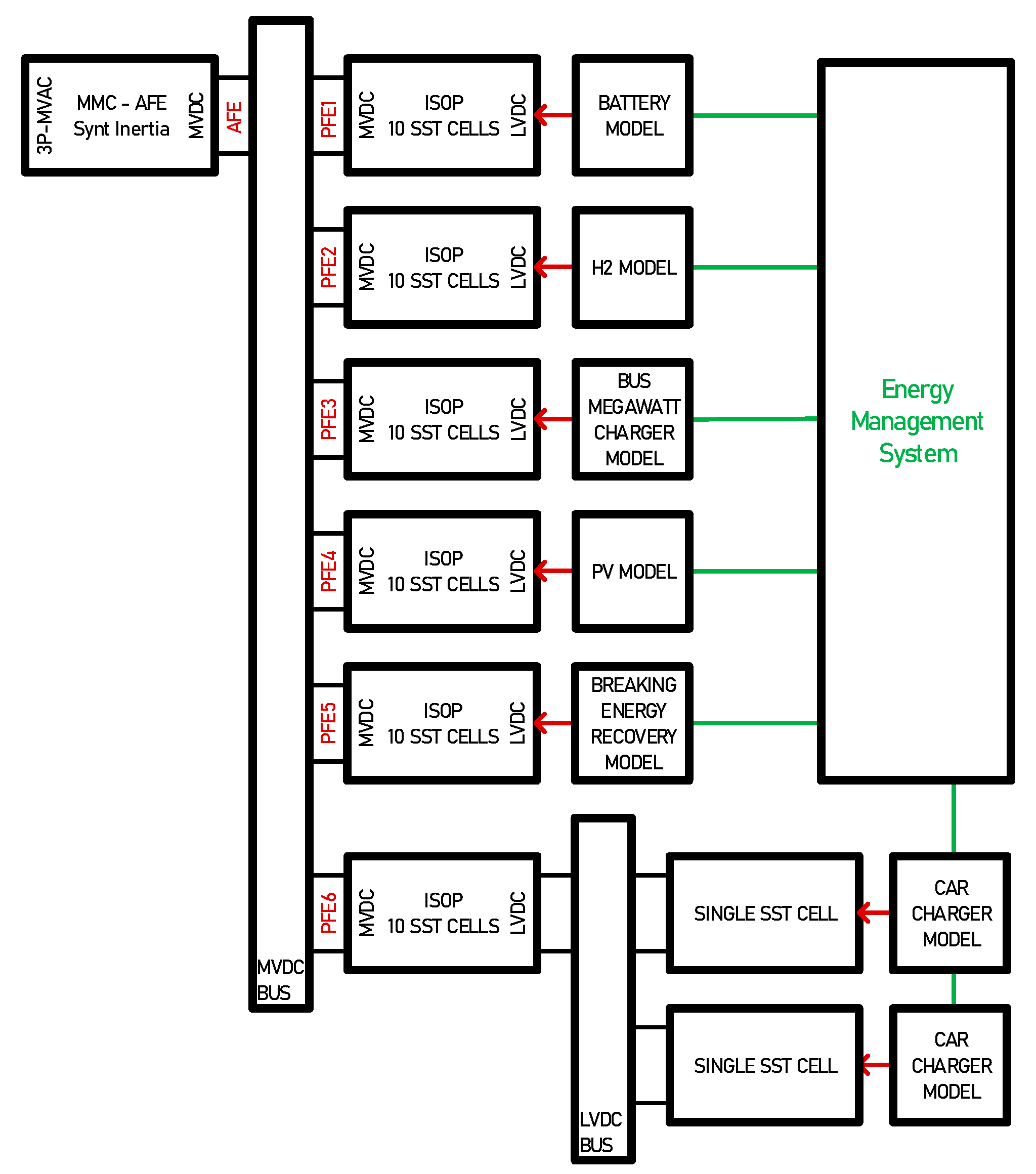
Figure 1 is entirely modelled and simulated with the elementary building blocks presented so far. As illustrated in
Figure 16, an MVDC bus interfaces an AFE with several 10-cell ISOP blocks. The AFE maintains the voltage with a dynamic defined by its capacitive inertia and the voltage controller’s time constant. One of the 10-cell ISOP blocks interfaces an LVDC bus where single SST blocks are connected for modelling bidirectional fast chargers for car batteries. This model features 73 SSTs working together, the model took less than a minute to simulate 1s simulation time with a simulation time step ts=1µs, with a quite standard computer, whereas a switching model would have taken about an hour.
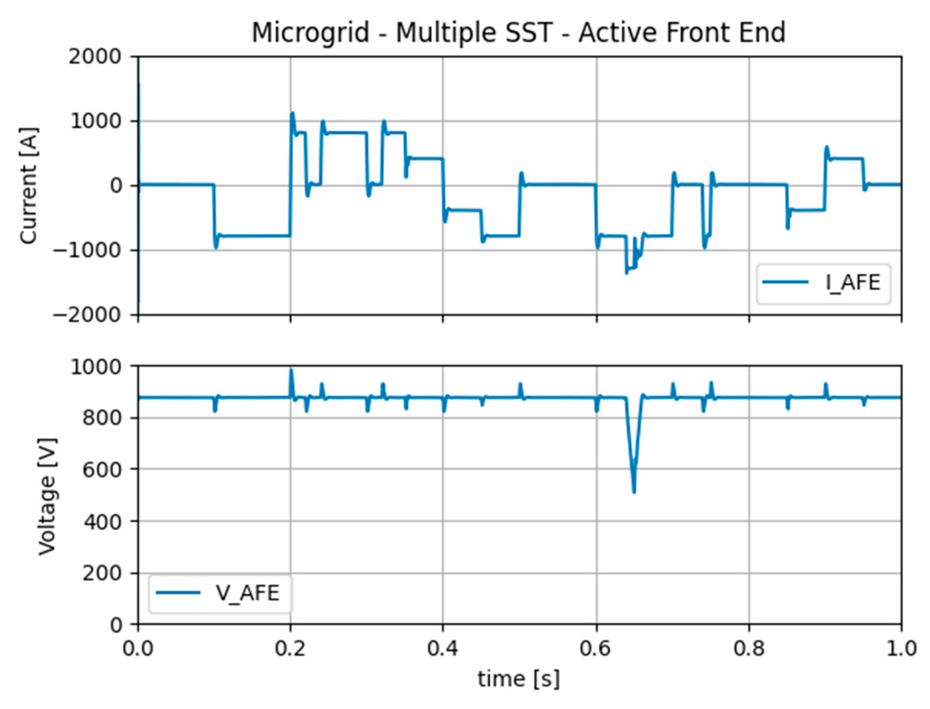
The simulated scenario involves PV energy drops, grid support from car chargers, and an MMC AFE current limiter for illustrating possible limitations of the system.
In
Figure 17, the current load of the MMC-Active Front End supplying the microgrid with multiple SST is presented. One can see that when current/power limit is reached, the AFE fails to supply enough energy into the DC Microgrid, thus having voltage dropping. At that moment Energy Management enables grid support from the EVs.
4.2. Continuous Time Model Interface
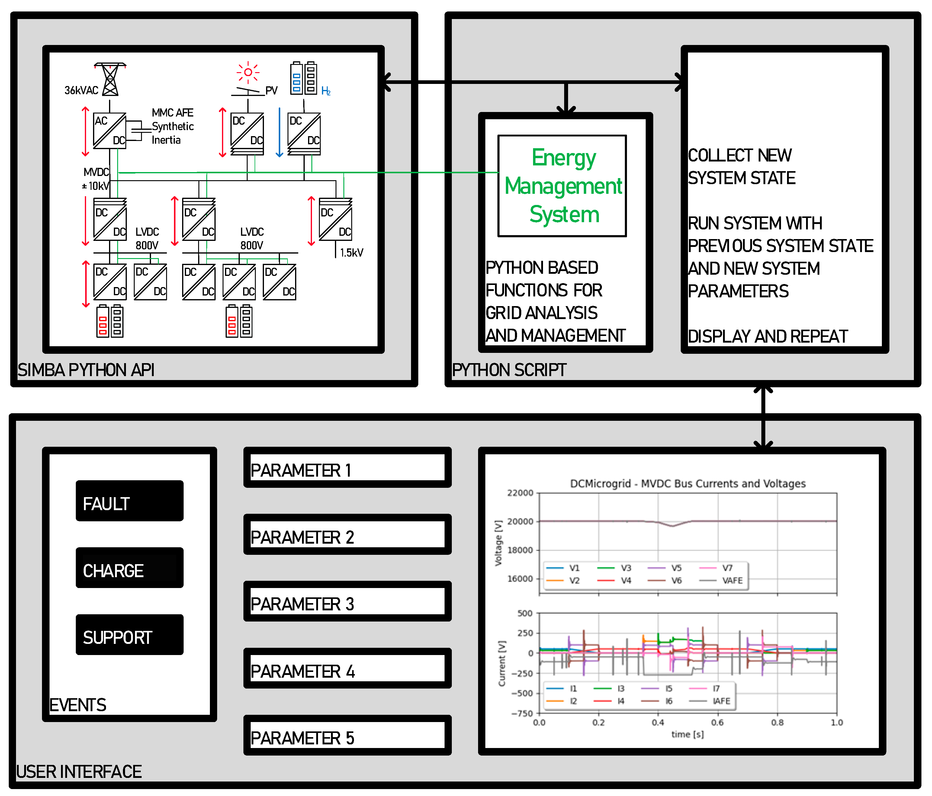
The previously described system is this run by a Python script calling the Simba Python API. The system is run for a short period of time, typically a fraction of a second. The state of the system is returned and displayed in the graphic user interface as illustrated in
Figure 18.
From this collected state, an iterative process can be established: analysis is run for possible actions on the grid, new parameters are collected from the graphic user interface, and a new run is initiated with the new states, and so on...
The Continuous Time Simulation Interface is a continuously run model on which actions can be performed. Those actions are either manually performed from the graphic user interface, or from Python based automated algorithms.
5. Discussion
This work presented a system modelling technique applied to modern MVDC systems. By using equivalent voltage/current sources, a complex MVDC system can be run fast with a realistic degree of accuracy, independent from its simulation environment. In this work, the model of the MVDC system was implemented in Simba.io environment because of the Python API it features. This allowed to run the model from a continuously run Python script with a dedicated graphic user interface. This way of operating, called « Continuous Time Simulation », allows to manually interact with the system or algorithmic run analysis and system level management tested.This feature is interesting, because if a library or an API is available, one could even envision real complex algorithmic grid management systems, with some modern DM or AI based systems, and quickly simulate them in a realistic grid model. With the proposed modelling approach, one can of course also envision running complex system for testing or educational purpose.
Further work will include AC aspects related to the MMC-AFE such as phase unbalance and transformer connections. Also, DC transmission cable models may be added with their capacitive components. On the control side, some data mining or AI approach could be studied with the use of available Python libraries.
Author Contributions
Conceptualization, Daniel Siemaszko and Mauro Carpita; methodology, Daniel Siemaszko and Mauro Carpita; software, Daniel Siemaszko; validation, Daniel Siemaszko and Mauro Carpita; formal analysis, Daniel Siemaszko and Mauro Carpita; investigation, Daniel Siemaszko and Mauro Carpita ; resources, Mauro Carpita; data curation, Daniel Siemaszko; writing—original draft preparation, Daniel Siemaszko ; writing—review and editing, Daniel Siemaszko and Mauro Carpita; visualization, Daniel Siemaszko; supervision, Daniel Siemaszko and Mauro Carpita. All authors have read and agreed to the published version of the manuscript.
Funding
This research received no external funding.
Data Availability Statement
No Data is available for this research
Acknowledgments
Contributions of T. Umuhire and M. Félix in the frame of their Bachelor thesis at HEIG-VD, under the supervision of the authors. The authors would also like to acknowledge the contributions of E. Rutovic ad G. Fontés from Aesim-Simba for their technical expertise and contribution to the modelling and Python interfaces..
Conflicts of Interest
The authors declare no conflicts of interest.
Nomenclature
| AI |
Artificial Intelligence |
| AFE |
Active Front End |
| DAB |
Dual Active Bridge |
| DM |
Data Mining |
| EV |
Electric Vehicle |
| ISOP |
Input Series Output Parallel |
| MMC |
Modular Multilevel Convert |
| LVDC |
Low-Voltage DC |
| MFT |
Medium Frequency Transformer |
| MMC |
Modular Multilevel Converter |
| MVDC |
Medium-Voltage DC |
| PFE |
Passive Front End |
| PPC |
Point of Common Coupling |
| REG |
Renewable Energy Generation |
| SoC |
State of Charge (battery related) |
| SST |
Solid State Transformer |
| ST |
Smart Transformer |
| UPS |
Uninterrupted Power Supply |
References
- W. Li et al., "State of the Art of Researches and Applications of MVDC Distribution Systems in Power Grid," IECON 2019 - 45th Annual Conference of the IEEE Industrial Electronics Society, Lisbon, Portugal, 2019, pp. 5680-5685. [CrossRef]
- Y. Lin and L. Fu, "A Study for a Hybrid Wind-Solar-Battery System for Hydrogen Production in an Islanded MVDC Network," in IEEE Access, vol. 10, pp. 85355-85367, 2022.
- D. Das and C. Kumar, "Partial Startup Scheme for Smart Transformer in Meshed Hybrid Islanded Grid Operation," in IEEE Transactions on Industry Applications, vol. 58, no. 1, pp. 142-151, Jan.-Feb. 2022.
- H. V. M., C. Kumar and M. Liserre, "An MVDC-Based Meshed Hybrid Microgrid Enabled Using Smart Transformers," in IEEE Transactions on Industrial Electronics, vol. 69, no. 4, pp. 3722-3731, April 2022.
- X. Zhao et al., "DC Solid State Transformer Based on Three-Level Power Module for Interconnecting MV and LV DC Distribution Systems," in IEEE Transactions on Power Electronics, vol. 36, no. 2, pp. 1563-1577, Feb. 2021.
- H. Jin, W. Chen, K. Hou, S. Shao, L. Shu and R. Li, "A Sharing-Branch Modular Multilevel DC Transformer with Wide Voltage Range Regulation for DC Distribution Grids," in IEEE Transactions on Power Electronics, vol. 37, no. 5, pp.
- Y. Zhuang et al., "A Multiport DC Solid-State Transformer for MVDC Integration Interface of Multiple Distributed Energy Sources and DC Loads in Distribution Network," in IEEE Transactions on Power Electronics, vol. 37, no. 2, pp. 2283-2296, Feb. 2022.
- G. Sha et al., "Research on Multi-Port DC-DC Converter Based on Modular Multilevel Converter and Cascaded H Bridges for MVDC Applications," in IEEE Access, vol. 9, pp. 95006-95022, 2021.
- S. Zhao, Y. Chen, S. Cui and J. Hu, "Modular Multilevel DC-DC Converter with Inherent Bipolar Operation Capability for Resilient Bipolar MVDC Grids," in CPSS Transactions on Power Electronics and Applications, vol. 7, no. 1, pp. 37-48, March 2022.
- J. Zhang, Y. Zhang, J. Zhou, J. Wang, G. Shi and X. Cai, "Control of a Hybrid Modular Solid-State Transformer for Uninterrupted Power Supply Under MVdc Short-Circuit Fault," in IEEE Transactions on Industrial Electronics, vol. 70, no. 1, pp. 76-87, Jan. 2023.
- A. R. Sadat and H. S. Krishnamoorthy, "Fault-Tolerant ISOSP Solid-State Transformer for MVdc Distribution," in IEEE Journal of Emerging and Selected Topics in Power Electronics, vol. 9, no. 6, pp. 6985-6996, Dec. 2021.
- J. Liao, N. Zhou, Z. Qin, P. Purgat, Q. Wang and P. Bauer, "Coordination Control of Power Flow Controller and Hybrid DC Circuit Breaker in MVDC Distribution Networks," in Journal of Modern Power Systems and Clean Energy, vol. 9, no. 6, pp. 1257-1268, November 2021.
- Y. Wang et al., "A Practical DC Fault Ride-Through Method for MMC Based MVDC Distribution Systems," in IEEE Transactions on Power Delivery, vol. 36, no. 4, pp. 2510-2519, Aug. 2021.
- X. Feng, Q. Xiong, A. L. Gattozzi and R. E. Hebner, "Partial Discharge Experimental Study for Medium Voltage DC Cables," in IEEE Transactions on Power Delivery, vol. 36, no. 2, pp. 1128-1136, April 2021.
- L. C. Hunter, C. D. Booth, A. Egea-Alvarez, A. Dyśko, S. J. Finney and A. Junyent-Ferré, "A New Fast-Acting Backup Protection Strategy for Embedded MVDC Links in Future Distribution Networks," in IEEE Transactions on Power Delivery, vol. 36, no. 2, pp. 861-869, April 2021.
- J. H. Van Sickel and K. Y. Lee, "Distributed Discrete Event and Pseudo Real-Time Combined Simulation for Multi-Agent Controlled Power Plants," 2009 15th International Conference on Intelligent System Applications to Power Systems, Curitiba, Brazil, 2009, pp. 1-6. [CrossRef]
- J. Robertson, G. P. Harrison and A. R. Wallace, "A pseudo-real time distribution network simulator for analysis of coordinated ANM control strategies," CIRED 2012 Workshop: Integration of Renewables into the Distribution Grid, Lisbon, 2012, pp. 1-4. [CrossRef]
- Bin Lu, A. Monti and R. A. Dougal, "Real-time hardware-in-the-loop testing during design of power electronics controls," IECON'03. 29th Annual Conference of the IEEE Industrial Electronics Society (IEEE Cat. No.03CH37468), Roanoke, VA, USA, 2003, pp. 1840-1845 Vol.2. [CrossRef]
- A. Kiffe, S. Formann, T. Schulte and J. Maas, "Hardware-in-the-loop capable state-space-averaging models for power converters in discontinuous conduction mode considering parasitic component behavior," Proceedings of the 2011 14th European Conference on Power Electronics and Applications, Birmingham, UK, 2011, pp. 1-10.
- G. Nayak and A. Dasgupta, "Full Order Averaged Modelling for Modular Solid State Transformer," 2020 IEEE International Conference on Power Electronics, Drives and Energy Systems (PEDES), Jaipur, India, 2020, pp. 1-6. [CrossRef]
- J. Yang, G. Buticchi, H. Yan, C. Gu, H. Zhang and P. Wheeler, "Impedance-based Sensitivity Analysis of Dual Active Bridge DC-DC Converter," 2019 IEEE 13th International Conference on Compatibility, Power Electronics and Power Engineering (CPE-POWERENG), Sonderborg, Denmark, 2019, pp. 1-5. [CrossRef]
- D. Siemaszko and P. Noisette, "Power System Simulation Tool for Quick Benchmarking of Innovative MVDC Grids in E-Mobility Applications," 2022 24th European Conference on Power Electronics and Applications (EPE'22 ECCE Europe), 2022.
- De Donker, M. Stieneker and R.W. De Doncker, "Dual-Active Bridge DC-DC Converter Ssystems for Medium-Voltage DC Distribution Grids", Power Electronics Conference 2015. COBEP 2015, Dec. 2015.
- P. Barrade : Électronique de Puissance, Presses Polytechniques et Universitaires Romandes. 2006.
- https://simba.io/.
- Heinig S., Siemaszko D., Baumann R. Hubatka N., Klaeusler M., Ruiz R., Burkart R., Yuan C.: Experimental Insights into the MW Range Dual Active Bridge with Silicon Carbide Devices, International Power Electronics Conference IPEC-Himeji 2022 - ECCE ASIA.
- L. Angquist, A. Antonopoulos, D. Siemaszko, K. Ilves, M. Vasiladiotis and H. -P. Nee, "Open-Loop Control of Modular Multilevel Converters Using Estimation of Stored Energy," in IEEE Transactions on Industry Applications, vol. 47, no. 6, pp. 2516-2524, Nov.-Dec. 2011. [CrossRef]
- S. Milovanović, M. Luo and D. Dujić, "Virtual Capacitor Concept for Computationally Efficient and Flexible Real-Time MMC Model," in IEEE Access, vol. 9, pp. 144211-144226, 2021, doi: 10.1109/ACCESS.2021.3121351.and brackets to indicate the reference number and page numbers; for example [5] (p. 10), or [6] (pp. 101–105). [CrossRef]
Figure 1.
Simulated Power System including MMC Active Front End and SSTs, represented by multiple isolated DC/DC converters.
Figure 1.
Simulated Power System including MMC Active Front End and SSTs, represented by multiple isolated DC/DC converters.
Figure 2.
System level model of the SST.
Figure 2.
System level model of the SST.
Figure 3.
SST cell model dynamics run with various Integral gains.
Figure 3.
SST cell model dynamics run with various Integral gains.
Figure 4.
Dynamic performance comparison between switching model and average model of the SST model.
Figure 4.
Dynamic performance comparison between switching model and average model of the SST model.
Figure 5.
SST cell model connecting a battery to an AFE through a DC PCC.
Figure 5.
SST cell model connecting a battery to an AFE through a DC PCC.
Figure 6.
State of Charge of the Battery connected to the SST.
Figure 6.
State of Charge of the Battery connected to the SST.
Figure 7.
Active Front End with synthetic inertia and equivalent grid strength.
Figure 7.
Active Front End with synthetic inertia and equivalent grid strength.
Figure 8.
Active Front End with synthetic inertia and equivalent grid strength.
Figure 8.
Active Front End with synthetic inertia and equivalent grid strength.
Figure 9.
System Sampling and Control Implementation – SST Case.
Figure 9.
System Sampling and Control Implementation – SST Case.
Figure 10.
IPOS configuration of 6 SSTs.
Figure 10.
IPOS configuration of 6 SSTs.
Figure 11.
IPOS configuration of 6 SSTs – asymmetric loading from MVDC.
Figure 11.
IPOS configuration of 6 SSTs – asymmetric loading from MVDC.
Figure 12.
IPOS configuration of 6 SSTs – current sharing on the primary side.
Figure 12.
IPOS configuration of 6 SSTs – current sharing on the primary side.
Figure 13.
IPOS configuration of 6 SSTs - current sharing on the secondary side.
Figure 13.
IPOS configuration of 6 SSTs - current sharing on the secondary side.
Figure 14.
ISOP configuration of 10 SSTs.
Figure 14.
ISOP configuration of 10 SSTs.
Figure 15.
ISOP configuration of 10 SSTs – current sharing on primary side.
Figure 15.
ISOP configuration of 10 SSTs – current sharing on primary side.
Figure 16.
Simulated Power System including MMC active front end and SSTs.
Figure 16.
Simulated Power System including MMC active front end and SSTs.
Figure 17.
Current load on the Active Front End supplying the Microgrid.
Figure 17.
Current load on the Active Front End supplying the Microgrid.
Figure 18.
Functioning of the Continuous Time Simulation Interface.
Figure 18.
Functioning of the Continuous Time Simulation Interface.
Table 1.
List of considered SST Cell parameters.
Table 1.
List of considered SST Cell parameters.
| |
Symbol |
Value |
Comment |
| DC nominal voltage on primary side |
VPRIM
|
1000V |
Set by grid model VGRID
|
| DC nominal voltage on secondary side |
VSEC
|
2000V |
Controlled by SST |
| nominal current on secondary side |
ISEC
|
250A |
Set by load model ILOAD
|
| maximum current on secondary side |
ISEC_MAX
|
300A |
Controlled by SST |
| MFT side SST inductance |
LMFT
|
8.5µH |
Defines control’s time response |
| DC side SST capacitor |
CDC
|
3mF |
Defines control’s time response |
| MFT switching frequency |
fSW
|
10kHz |
Defines control’s transfer function |
| Simulation time step |
ts
|
1µs |
This time step is used in all runs |
|
Disclaimer/Publisher’s Note: The statements, opinions and data contained in all publications are solely those of the individual author(s) and contributor(s) and not of MDPI and/or the editor(s). MDPI and/or the editor(s) disclaim responsibility for any injury to people or property resulting from any ideas, methods, instructions or products referred to in the content. |
© 2024 by the authors. Licensee MDPI, Basel, Switzerland. This article is an open access article distributed under the terms and conditions of the Creative Commons Attribution (CC BY) license (http://creativecommons.org/licenses/by/4.0/).
