1. Introduction
Radio telescope serves as the key equipment to receive and detect radio waves from the universe, which plays an important role in space communication, deep space exploration, radio astronomy, and other research fields. In order to better receive and detect radio signals from distant space, a new generation of radio telescopes is tending to develop larger diameters. So far, there are two fully steerable radio telescopes in the world with apertures up to 100 meters, namely the Effelsberg radio telescope[
1] and the Green Bank telescope[
2]. In addition, China is building a 110-m fully-steerable radio telescope in Qitai, Xinjiang Province[
3], and a 120-m fully-steerable radio telescope in Jingdong, Yunnan Province[
4].
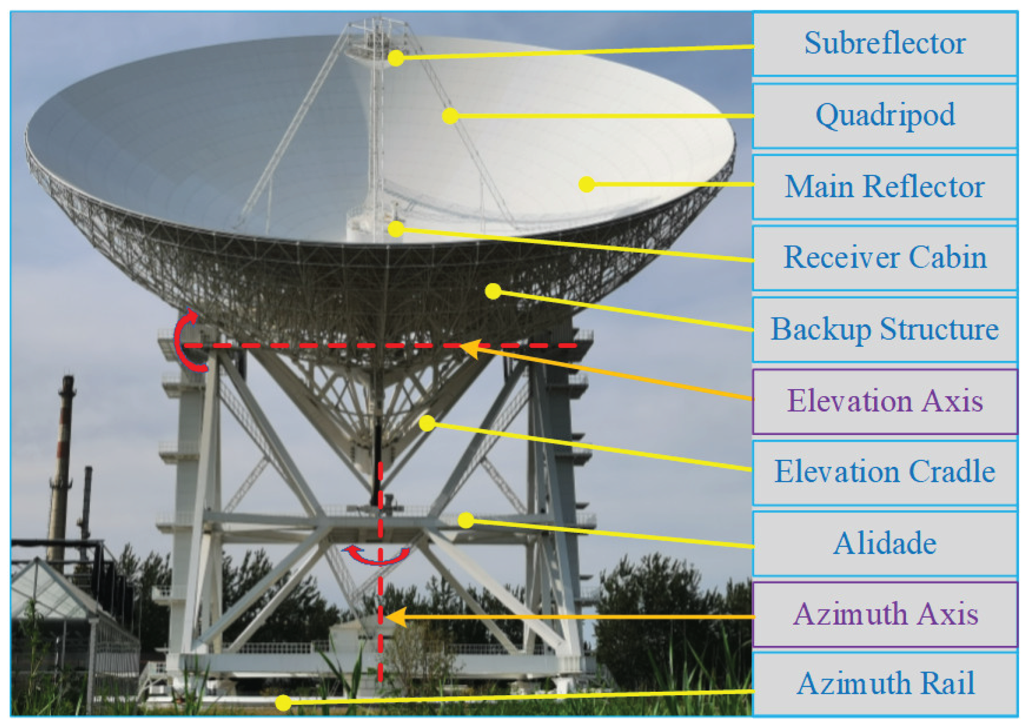
The Wuqing 70-m radio telescope(WRT70) is a typical wheel-track fully-steerable radio telescope, which is shown in
Figure 1. Theoretically, the fully steerable radio telescope can point to any direction in horizontal space by driving the antenna to rotate around the vertical azimuth axis and the horizontal elevation axis, separately. In fact, there is always a large deviation between the commanded direction and the actual direction of a large fully steerable radio telescope, due to the influence of structure errors, installation errors, servo errors, gravity, and varying environmental factors[
5]. The deviation is defined as the pointing error of radio telescopes, which is usually required not to exceed 1/10 of the beam width (half power beam width, HPBW)[
6]. The larger the aperture of radio telescopes is, the smaller the allowable pointing error is. Therefore, the excessive pointing error of a large fully steerable radio telescope must be estimated and calibrated effectively. Generally, the pointing error caused by the antenna’s structure errors, installation errors, servo errors, and gravity is repeatable and static, which can be estimated and calibrated by the classic multi-parameter pointing model[
7]. However, the dynamic pointing error caused by varying environmental factors(including solar radiation and wind disturbance) is unrepeatable and time-varying, so estimating and calibrating it becomes very difficult[
8].
In order to estimate the dynamic pointing error, the thermal behaviors of radio telescopes under solar radiation have been discussed internationally. Over the past decades, the thermal behaviors of many foreign radio telescopes have been studied overseas via combining finite-element (FE) calculations and relative experiments, including the thermal deformation of the reflector system of the RT-70 radio telescope[
9], the thermal design of the quadripod and backup structure of the IRAM 30-m telescope[
10], and the thermal analysis of the alidade of the Medicina 32-m telescope and the Sardinia 64-m telescope[
11,
12,
13]. In recent years, the thermal behaviors of several domestic radio telescopes also have been researched in China based on FE analysis and experimental measurements, such as the thermal effects of the alidade of the Nanshan 25-m radio telescope and the Miyun 50-m radio telescope[
14,
15], the nonuniform temperature and the thermal behavior of the Tianma 65-m radio telescope[
16,
17], the thermal deformations of the alidade and the reflector system of WRT70 [
18,
19]. To sum up, extensive studies on the thermal behaviors of radio telescopes have been done, but the research on estimating the total pointing error caused by the thermal behaviors of large radio telescopes is poor. There is still no effective way to estimate the dynamic pointing error of large radio telescopes under solar radiation up to now.
With the developments of new generation information technologies (New IT), digital twin (DT) has attracted researchers’ attention and has been applied in the field of radio technology[
20,
21,
22]. DT can create a digital model consistent with a physical device to simulate and predict the running state of the actual device[
23]. In digital models, the behaviors and rules of a physical device can be represented by multidimensional models and multi-class parameters. Therefore, it will be very promising to use DT to predict the dynamic pointing error of large radio telescopes under solar radiation. In this paper, WRT70 is taken as the research object. Based on the DT system, the thermal behaviors of WRT70 under solar radiation can be presented in visual cloud images, and the dynamic pointing error caused by the thermal behaviors can be estimated via the rule model of pointing error. In
Section 2, the operational framework of the DT system of large radio telescopes is introduced. In
Section 3, the digital models of WRT70 are constructed, including the geometric model, physical model, behavior model, and rule model. In
Section 4, the twin data of WRT70 is verified, and the pointing errors of WRT70 on two specific sunny days are estimated.
2. Operational Framework of the DT System of Large Radio Telescopes
According to the five-dimensional conceptual model of DT proposed by Professor F. Tao of Beihang University, the DT system of large radio telescopes consists of five parts, including physical telescope device, digital telescope model, twin data, service, and connection and interaction between units[
24]. The operational framework of the DT system of large radio telescopes can be represented in
Figure 2.
First, the local state data of large radio telescopes is collected in real-time via a series of sensors installed on the physical telescope device, and stored in the data center of the observation station. Meanwhile, the digital telescope models are created by computer software based on the sensors sensing data. Then the global state of the physical telescope device is simulated and calculated by the digital telescope models based on the service unit. In addition, the twin data generated by the digital telescope models can be verified by the sensors sensing data, and the digital telescope models can be optimized and updated when necessary. Finally, the behaviors and rules of the physical telescope device can be predicted by analyzing the twin data.
3. Creation of the Digital Models of WRT70
The core task of building a DT system is to create digital models. The creation of the digital models of WRT70 includes geometric modeling, physical modeling, behavior modeling, and rule modeling, which will be described in detail below.
3.1. Geometric Modeling
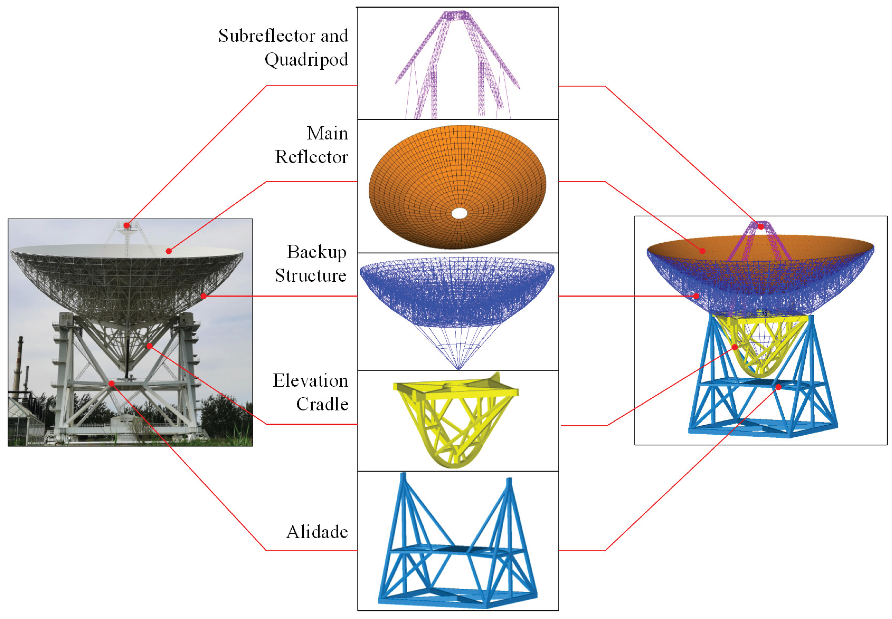
Geometric modeling refers to the process of constructing a three-dimensional model of one geometric entity inside the computer by CAD software. There are two common CAD modeling methods: the GUI manual modeling and the instruction parametric modeling. In order to facilitate the modification of the geometric model and improve the modeling efficiency, the instruction parametric modeling is adopted here. The antenna’s structure of WRT70 can be divided roughly into five components: alidade structure, elevation cradle, backup structure, main reflector, subreflector, and quadripod. Based on the geometric size and matching feature data of each component, the three-dimensional geometric model of WRT70 is constructed as
Figure 3. The alidade serves as the foundation of WRT70, which can move around the vertical azimuth axis on the azimuth rail. The elevation cradle and the above structures are supported by the alidade via two elevation bearings, which can rotate around the horizontal elevation axis as a whole.
The alidade structure is a large spatial A-shaped truss, which is assembled by 52 rectangular beams with different cross-section sizes. The elevation cradle is composed of a diamond-cross truss, a half-big gear, and several diagonal-braced rectangular beams. The backup structure is a complex truss structure with circular symmetry, including an umbrella-support truss, a central main truss, 32 identical radial string beams, 320 ring string beams of different kinds, and hundreds of auxiliary round beams. The main reflector is a paraboloid with a diameter of 70 meters, which is composed of 1328 fan-shaped aluminum plates. The subreflector and quadripod include a hyperboloid-type subreflector with a diameter of 6 meters and a quadripod truss, where the subreflector is supported by the quadripod.
3.2. Physical Modeling
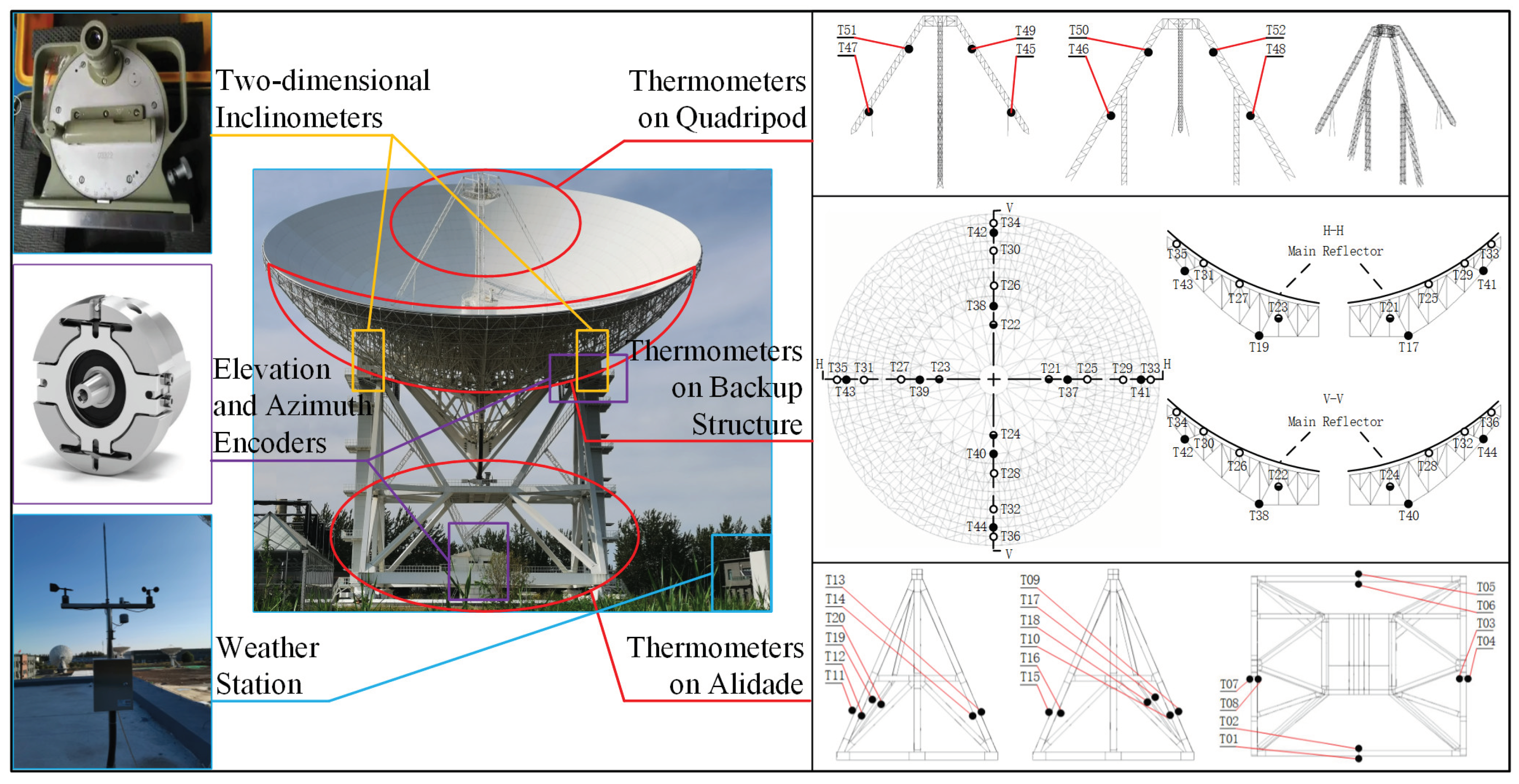
Physical modeling refers to the process of loading the boundary load data, measured by sensors from the physical telescope device, into the digital telescope model after equivalent transformation. Our team has installed various sensors on the physical structure of the WRT70 in past work, including 52 thermometers, 2 inclinometers, and 2 encoders. In addition, a weather station was installed around the physical entity of the WRT70 to monitor the environmental data such as atmospheric pressure, air temperature and humidity, solar radiation intensity, etc. The distribution of the above sensors on the WRT70 is shown in
Figure 4, where unfortunately the left one of the two-dimentional inclinometers is broken now.
The reflector system(including backup structure, main reflector, subreflector, and quadripod) and the alidade structure of WRT70 are affected significantly by environmental factors. In order to facilitate the setting of boundary conditions and the loading of external loads, FE modeling is considered as the main way of physical modeling. The element number of the whole FE model of WRT70 is very huge so the periods of the FE modeling and simulation are extremely long. Due to the consideration of computer modeling and analysis speed, the reflector system and the alidade of WRT70 are physically modeled separately here. The FE models of the reflector system and the alidade and the marks of the applied boundary loads are shown in
Figure 5. The temperature load is applied to the element nodes of the FE models in the form of surface convection heating and equivalent node temperature. The gravitational load is loaded onto the element nodes of the FE models in the form of gravitational acceleration. And the corresponding material properties of WRT70 are listed in
Table 1.
3.3. Behavior Modeling
Behavior modeling refers to the process of obtaining the behavior characteristics of physical entity through digital simulation. Based on geometric modeling and physical modeling, the behavior characteristics of WRT70 can be obtained through FE simulation. The non-uniform temperature distributions and the corresponding thermal deformations of WRT70 under solar radiation can be visualized by contours, as shown in
Figure 6 and
Figure 7.
3.4. Rule Modeling
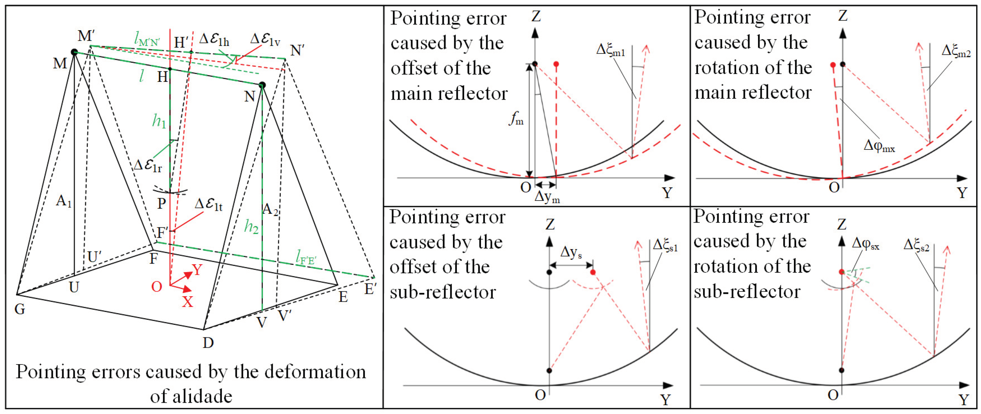
Rule modeling refers to the process of obtaining the specific rules of the physical device through mathematical modeling and iterative calculation of the behavior characteristic data analyzed by the digital model. The dynamic rule of the pointing error of WRT70 under solar radiation is most desirable to be obtained in this paper. The pointing error of WRT70 is closely related to the tilt of the alidade and the pose variations of the reflector system, which is simply depicted in
Figure 8. The tilt of the alidade can be simply calculated by combining the deformation displacement of several special nodes on the alidade, which will not be covered here. While the pose variations of the reflector system can only be solved by mathematical modeling and iterative calculation.
3.4.1. Pose Variation Rule of Reflector System
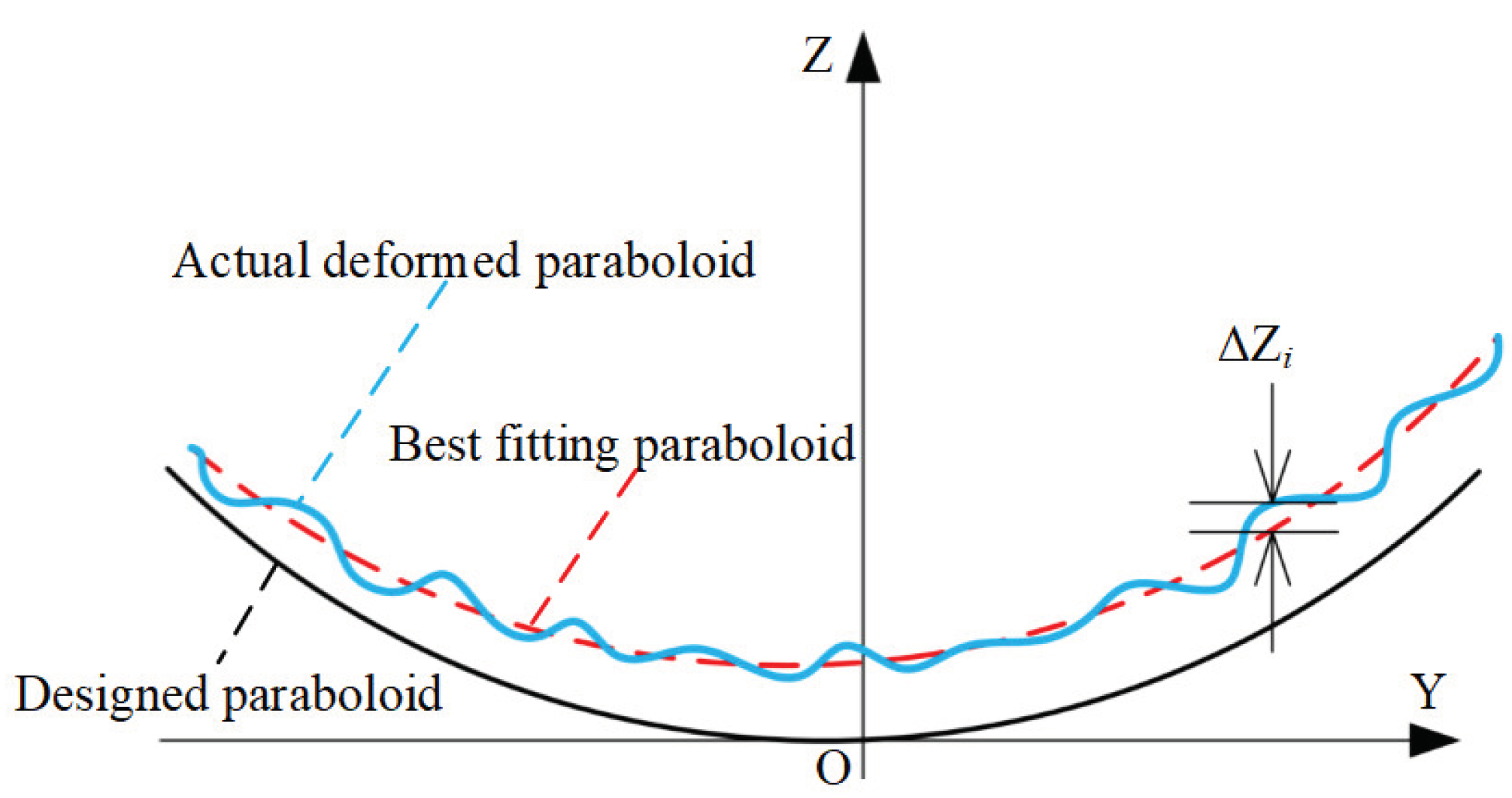
The pose variations of the main reflector need to be determined by solving the mathematical model of the best-fitting paraboloid of the deformed main reflector. The best-fitting paraboloid is a virtual paraboloid closest to the deformed main reflector, shown in
Figure 9.
The expression of the best fitting paraboloid is given as
where
,
,
are the offsets of the best fitting paraboloid relative to the designed paraboloid along the X-axis, Y-axis, and Z axis, respectively.
and
are the rotations of the best fitting paraboloid relative to the designed paraboloid at the apex around the X axis and Y axis, respectively.
is the offset of the focal length of the best-fitting paraboloid relative to the focal length of the designed paraboloid. The relationship between the above six key parameters and the displacement of each node on the main reflector could be expressed as[
25]
where
According to Equation
2, the pose variations of the main reflector, including
,
,
,
, and
, could be determined.
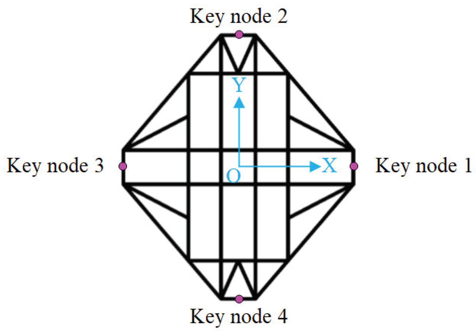
The subreflector of WRT70 is fixed to the top of the quadripod. The pose variations of the subreflector can be almost equivalent to the ones of the top of the quadripod. There are four key nodes on the top structure of the quadripod, shown in
Figure 7. Based on the displacement of the key nodes 1 to 4, the pose variations of the subreflector could be equivalently converted. The offsets
,
and
of the actual subreflector relative to the designed subreflector along X axis, Y axis, and Z axis could be expressed as Equation
6 to Equation
8, respectively[
19]. The rotations
and
of the actual subreflector relative to the designed subreflector at the focus around X axis and Y axis could be expressed as Equation
9 and Equation
10, respectively[
19]. (
,
,
), (
,
,
), (
,
,
) and (
,
,
) are the displacement of the key nodes 1 to 4, respectively.
3.4.2. Pointing Error Rule of WRT70
The pointing error of radio telescopes can be subdivided into elevation pointing error, horizontal cross-elevation pointing error, and vertical cross-elevation pointing error. According to the geometric relationship of the alidade shown in
Figure 8, the elevation pointing error
caused by the rotation of the elevation cradle can be expressed as[
26]
the elevation pointing error
caused by the tilt deformation of the alidade can be expressed as[
26]
the horizontal cross-elevation pointing error
caused by the alidade deformation can be expressed as[
26]
the vertical cross-elevation pointing error
caused by the alidade deformation can be expressed as[
26]
where
and
are the displacements of A
1-tower top point M along the Y-axis and the Z-axis, respectively.
and
are the displacements of A
2-tower top point N along the Y-axis and the Z-axis, respectively.
is the Y-axis displacement of point P.
is the distance between the horizontal elevation axis and the elevation driver.
is the height of the horizontal elevation axis from the azimuth rail. And
l is the width of the alidade. In particular, the elevation pointing error
caused by the rotation of elevation cradle and the elevation pointing error
caused by the tilt deformation of alidade can be merged into the total elevation pointing error
of alidade due to the consistent pointing direction of both.
In order to estimate the pointing error caused by the pose variations of the reflector system of radio telescopes, the concept of beam deviation factor (BDF) was first proposed by Ruze in 1965. BDF is defined as the ratio of the beam deviation of radio telescopes to the focal-line deviation of the parabolic reflector. The expression of BDF could be given as[
27]
where
D is the diameter of the main reflector or subreflector,
f is the focal length of the primary focal or Cassegrain focal, and
is the taper parameter.
Based on BDF and geometric optical path of reflector system, the elevation pointing error
caused by the pose variations(
) of the reflector system can be expressed as[
27]
the horizontal cross-elevation pointing error
caused by the pose variations(
) of the reflector system can be expressed as[
27]
the vertical cross-elevation pointing error
caused by the pose variations(
) of the reflector system can be expressed as[
27]
where
M is equivalent to
,
a is the half of the real axis length of the hyperbolic subreflector,
c is the half of the focal length of the hyperbolic subreflector,
is the focal length of the parabolic reflector, and
is the elevation angle of WRT70.
Affected by varying environmental factors, the deformation of the alidade and reflector system WRT70 is the most significant. Ignoring the influence of azimuth rail and elevation cradle, the sum of the pointing errors caused by the deformation of the alidade and reflector system can be taken as the total pointing error of WRT70. Combining Equation
11 to
14 and Equation
16 to
18, the total elevation pointing error
of WRT70 can be expressed as
the total horizontal cross-elevation pointing error
of WRT70 can be expressed as
the total vertical cross-elevation pointing error
of WRT70 can be expressed as
4. Verification of Structural Temperature Data and Estimation of Pointing Error for WRT70 under Solar Radiation
Based on the DT system created above, the pointing error of WRT70 (keeping at the position of the elevation angle of 90° and the azimuth angle of 180°) on two specific sunny days(February 27, 2021, and June 5, 2021) is estimated in this paper. To verify the reliability of the above DT system, the structural temperature data and the pointing error data caused by the alidade deformation of the WRT70 are verifed below.
4.1. Verification of Structural Temperature Data
The distribution of the 52 temperature sensors on WRT70 is shown in
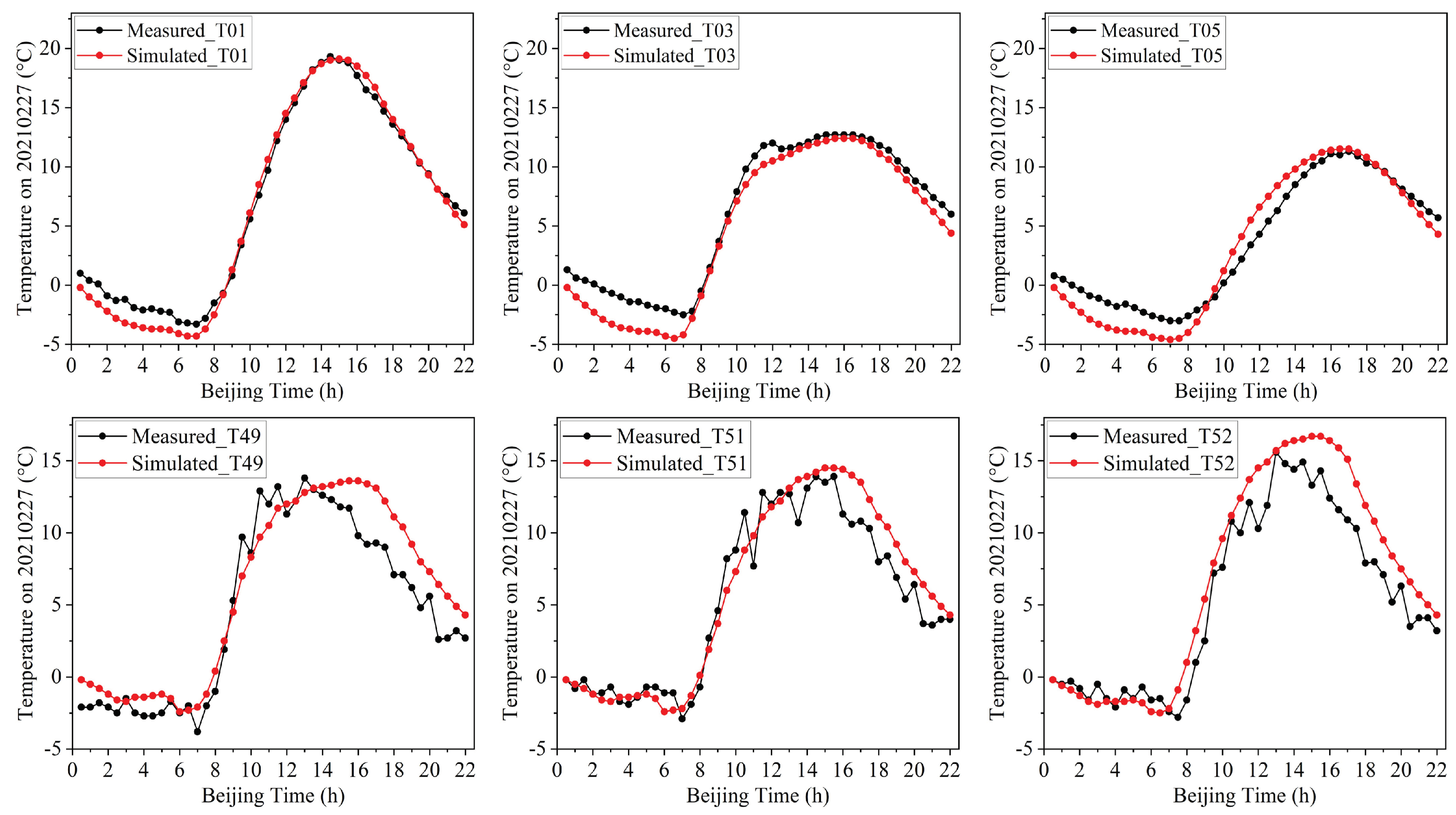
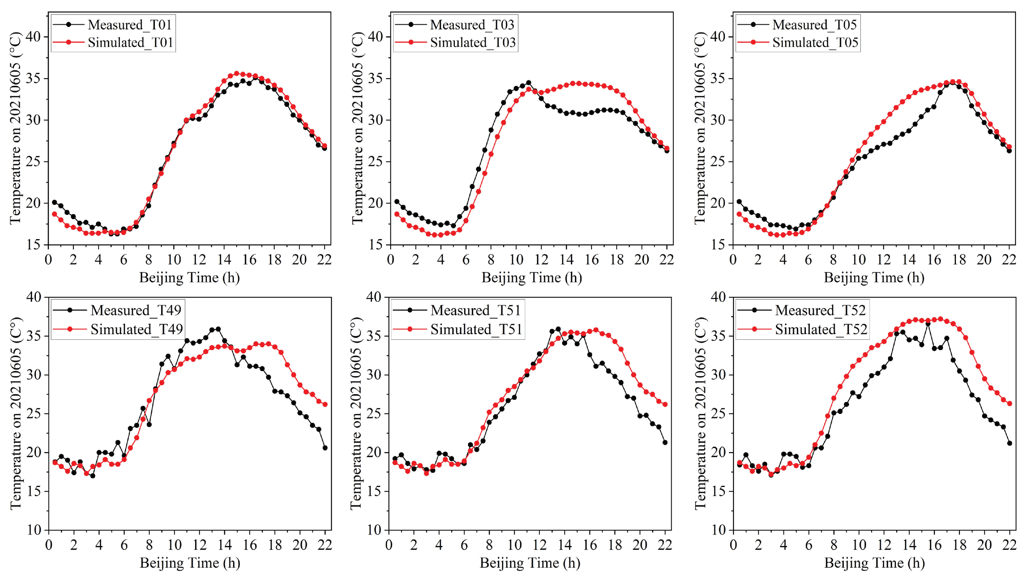
Figure 4, with 20 temperature sensors(T01 to T20) on alidade, 24 temperature sensors(T21 to T44) on backup structure, and 8 temperature sensors(T45 to T52) on quadripod. The simulated temperature data and the measured temperature data for several representative locations(T01, T03, T05 on alidade, and T49, T51, T52 on backup structure) on February 27, 2021, and June 5, 2021 are compared respectively in
Figure 11 and
Figure 12.
The comparison results in
Figure 11 and
Figure 12 show that the simulated temperature data and the measured temperature data at several representative locations of the alidade and backup structure are in good agreement. The temperature difference at different locations of the WRT70 on February 27, 2021 is larger than that on June 5, 2021.
4.2. Verification of Pointing Error Data Caused by Alidade Deformation
The pointing error caused by alidade deformation can be subdivided into four subitems(
,
,
, and
) to calculate according to Equation
11 to
14. Meanwhile, the elevation pointing error
caused by the rotation of elevation cradle and the horizontal cross-elevation pointing error
caused by alidade deformation can be measured by elevation and azimuth encoders, and the elevation pointing error
caused by the tilt deformation of alidade and the vertical cross-elevation pointing error
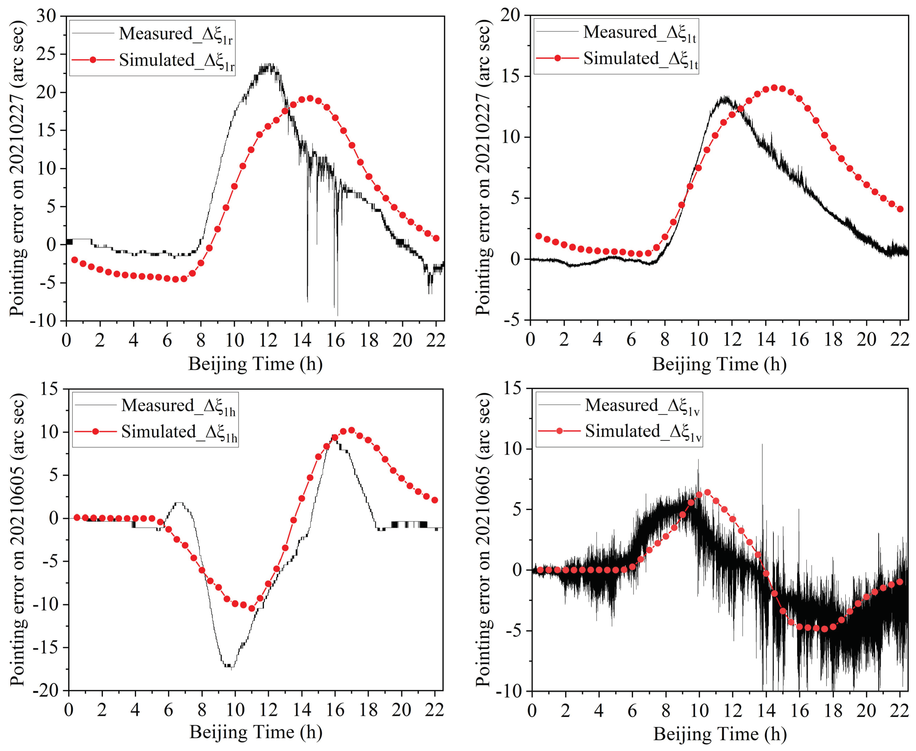
caused by alidade deformation can be measured by two-dimensional inclinometers. The calculated data and the measured data for the four subitems of the pointing error caused by alidade deformation of the WRT70 on February 27, 2021, and June 5, 2021, are compared in
Figure 13.
The comparison results in
Figure 13 show that the calculated data and the measured data for the four subitems(
,
,
, and
) of the pointing error caused by alidade deformation of the WRT70 are all in agreement to some degree. The fluctuation range of the elevation pointing error
caused by the rotation of the elevation cradle on February 27, 2021, is over 20 arcsec according to the calculated data and the measured data of the elevation encoder. The fluctuation range of the elevation pointing error
caused by the tilt deformation of the alidade on February 27, 2021, is close to 15 arcsec according to the calculated data and the measured data around the X axis of the two-dimensional inclinometer. The fluctuation range of the horizontal cross-elevation pointing error
caused by alidade deformation on June 5, 2021, is over 20 arcsec according to the calculated data and the measured data of the azimuth encoder. The fluctuation range of the vertical cross-elevation pointing error
caused by alidade deformation on June 5, 2021, is over 10 arcsec according to the calculated data and the measured data around the Y axis of the two-dimensional inclinometer.
4.3. Estimation of Total Pointing Error of WRT70
According to the rule model of the DT system established above, the total pointing errors of WRT70 under solar radiation can be calculated.
Figure 14 depicts the estimated results of the total pointing error of WRT70 under solar radiation on February 27, 2021, and June 5, 2021.
The above results show that the pointing error of WRT70 under solar radiation varies greatly and fluctuates sinusoidal, which should never be ignored. The elevation pointing error of WRT70 around the winter solstice is over 40 arcsec, which is much larger than that around the summer solstice. The horizontal cross-elevation pointing error of WRT70 around the winter solstice fluctuates little and much less than that around the summer solstice.
5. Conclusion
In this paper, the DT system of a large radio telescope is constructed and the total pointing error of WRT70 under solar radiation is estimated. According to the research results, the following conclusions can be drawn.
(1) The DT system of WRT70 constructed in this paper is reliable to a great degree. The simulated temperature data and the measured temperature data at several representative locations of WRT70 are proved to be in good agreement. The calculated data and the measured data for the four subitems of the pointing error caused by alidade deformation of the WRT70 are all in agreement to some degree.
(2) The total pointing error of large radio telescopes(staying at a specific position) under solar radiation can be calculated by the DT system. The total pointing error of WRT70(staying at the position of the elevation angle of 90° and the azimuth angle of 180°) on February 27, 2021, and June 5, 2021, is estimated based on the DT system in this paper.
(3) The pointing error of large radio telescopes under solar radiation fluctuates greatly and the seasonal differences are very striking, which should never be ignored. The maximum elevation pointing error of WRT70 around the winter solstice is over 40 arcsec, which is much larger than that around the summer solstice.
This study provides a feasible way to estimate the dynamic pointing error of large radio telescopes staying at a specific position. Unfortunately, the way is not yet able to estimate effectively the dynamic pointing error of large radio telescopes being in action. However, it will be promising for establishing a dynamic pointing error model and calibrating the dynamic pointing errors of large radio telescopes(being in action) by DT technology in the future.
Author Contributions
Data curation, K.D. and F.L.; Methodology, W.S.; Writing—original draft preparation, W.S.; Writing—review and editing, W.S. and K.D.; Software W.B.; Investigation, W.B. and X.Z.; Supervision, X.W., Y.Z. and L.Y. All authors have read and agreed to the published version of the manuscript.
Funding
This research was funded by the National Natural Science Foundation of China(Grant No. 12303091), the Scientific and Technological Innovation Team of Higher Education Institutions under the Education Department of Guizhou of China(Grant No. QJJ[2023]093), the Natural Science Research Project of Education Department of Guizhou of China(Grant No. QJJ[2022]398), the Bijie City Science and Technology Project(Grant No. BKLH[2023]18), the Natural Science Research Project of Guizhou Higher Education Institutions of China (Grant No. QJJ[2023]047), and the Bijie City Science and Technology Project (Grant No. BKLH[2023]9).
Data Availability Statement
Data is unavailable.
Conflicts of Interest
The authors declare no conflicts of interest.
Abbreviations
The following abbreviations are used in this manuscript:
| WTR70 |
Wuqing 70-m Radio Telescope |
| HPBW |
Half Power Beam Width |
| FE |
Finite Element |
| DT |
Digital Twin |
| New IT |
New generation Information Technologies |
References
- Wielebinski, R.; Junkes, N.; Grahl, B. The effelsberg 100-m radio telescope: construction and forty years of radio astronomy. Journal of Astronomical History and Heritage 2011, 14, 3–21. [Google Scholar] [CrossRef]
- Hunter, T.; Schwab, F.; White, S.; Ford, J.; Ghigo, F.; Maddalena, R.; Mason, B.; Nelson, J.; Prestage, R.; Ray, J.; Ries, P.; Simon, R.; Srikanth, S.; Whiteis, P. Holographic Measurement and Improvement of the Green Bank Telescope Surface. Publications of the Astronomical Society of the Pacific 2011, 123, 1087. [Google Scholar] [CrossRef]
- Wang, N. Introduction for QTT Project. Proceedings of 2019 URSI Asia-Pacific Radio Science Conference(AP-RASC), New Delhi, India, 09-15 March 2019. [Google Scholar]
- Wang, M.; Xu, Y.H.; Wang, J.C.; Li, D.W.; Wang, S.W.; Zhao, W.L.; Hao, L.F.; Cheng, X.M.; Dong, L.; He, G.X.; He, C.; Dai, W.; Li, Z.X.; Xu, C.; Yang, G.H.; Yang, F.H.; Gao, Y.F.; Gao, G.N.; Guo, S.J.; Chen, W.; Dong, J.; Huang, Y.X. Jingdong 120-m pulsar radio telescope. Sci. China Phys. Mech. Astron. 2022, 52, 119501. [Google Scholar] [CrossRef]
- Gawronski, W. Control and pointing challenges of antennas and telescopes. In Proceedings of the American Control Conference, Portland, OR, USA, 08-10 June 2005; Volume 6. [Google Scholar]
- Levy, R. Structural Engineering of Microwave Antennas, 1st ed.; IEEE Press: New York, NY, USA, 1996. [Google Scholar]
- Yu, L.F.; Wang, J.Q.; Zhao, R.B.; Dong, J.; Zuo, X.T.; Gou, W.; Liu, Q.H.; Fan, Q.Y. The Establishment of Pointing Model for the TM65 m Radio Telescope. Chinese Astronomy and Astrophysics 2015, 39, 524–537. [Google Scholar]
- Liang, W.; Huang, J.; Zhang, J. Real-Time Estimation of Wind-Induced Pointing Error via Accelerations Measurement for Large Reflector Antenna. IEEE Access 2020, 8, 71812–71820. [Google Scholar] [CrossRef]
- Borovkov, A.; Shevchenko, D.V.; Gimmelman, V.G.; Machuev, Y.I.; Gaev, A. Finite-element modeling and thermal analysis of the RT-70 radio telescope main reflector. Proceedings of 4th International Conference on Antenna Theory and Techniques, Sevastopol, Ukraine, 09-12 September 2003; Volume 2. [Google Scholar]
- Greve, A.; Bremer, M.; Penalver, J.; Raffin, P.; Morris, D. Improvement of the IRAM 30-m telescope from temperature measurements and finite-element calculations. IEEE Transactions on Antennas and Propagation 2005, 53, 851–860. [Google Scholar] [CrossRef]
- Pisanu, T.; Buffa, F.; Morsiani, M.; Pernechele, C.; Poppi, S. Thermal behavior of the Medicina 32 meter Radio Telescope. Proceedings of SPIE - The International Society for Optical Engineering, San Diego, California, United States, 22 July 2010; Volume 7739. [Google Scholar]
- Pisanu, T.; Buffa, F.; Poppi, S.; Marongiu, P.; Serra, G.; Vargiu, G.; Concu, R. The SRT inclinometer for monitoring the rail and the thermal gradient effects on the alidade structure. Proceedings of SPIE - The International Society for Optical Engineering, Montréal, Quebec, Canada, 22 July 2014; Volume 9145. [Google Scholar]
- Attoli, A.; Stochino, F.; Buffa, F.; Poppi, S.; Serra, G.; Sanna, G.; Sanna, G. Sardinia Radio Telescope structural behavior under solar thermal load. Structures 2022, 39, 901–916. [Google Scholar] [CrossRef]
- Xu, Q.; Xue, F.; Wang, H.; Yi, L. Measurement and Correction of Pointing Error Caused by Radio Telescope Alidade Deformation based on Biaxial Inclination Sensor. Micromachines 2023, 14, 1283. [Google Scholar] [CrossRef]
- Kong, D.Q.; Jiang, Z.Y.; Zhang, H.B.; Wu, Y.X. Effects of sunshine temperature on axis angle measurement errors of large radio telescopes and the correction method. Sci. Sin. Tech. 2019, 49, 1331–1342. [Google Scholar]
- Qian, H.L.; Chen, D.S.; Fan, F.; Liu, Y.; Shen, S.Z. Evaluation of solar temperature field under different wind speeds for Shanghai 65 m radio telescope. International Journal of Steel Structures 2016, 16, 383–393. [Google Scholar] [CrossRef]
- Fu, L.; Ling, Q.B.; Geng, X.G.; Wang, J.Q.; Jiang, Y.; Yu, L.F.; Zhang, Y. The alidade temperature behaviour of TM65m antenna and its effects on pointing accuracy. Proceedings of SPIE - The International Society for Optical Engineering, Edinburgh, United Kingdom, 22 July 2016; Volume 9912. [Google Scholar]
- Wei, S.X.; Kong, D.Q.; Wang, Q.M. Effect of the alidade thermal behavior on the pointing accuracy of a large radio telescope. Research in Astronomy and Astrophysics 2021, 21, 137. [Google Scholar] [CrossRef]
- Wei, S.X.; Kong, D.Q.; Wang, Q.M. Effect of the reflector system thermal behavior on the pointing accuracy of large radio telescopes. Journal of Astronomical Telescopes, Instruments, and Systems 2023, 9, 028002. [Google Scholar] [CrossRef]
- Bednarz, T.; Branchaud, D.; Wang, F.; Baker, J.; Marquarding, M. Digital Twin of the Australian Square Kilometre Array. Proceedings of SIGGRAPH Asia 2020, New York, NY, United States, 04 - 13 December 2020. [Google Scholar]
- Li, Q.W.; Jiang, P.; li, H. Prognostics and health management of FAST cable-net structure based on digital twin technology. Research in Astronomy and Astrophysics 2020, 20, 067. [Google Scholar] [CrossRef]
- Wen, J.J.; Liu, Z.G.; Song, Y.F.; Meng, X.K.; Yao,J. H. Rapid Modeling Method for The Digital Twin of Five-hundred-meter Aperture Spherical Radio Telescope. IAENG Internaitonal Journal of Computer Science 2022, 22, 482–488. [Google Scholar]
- Botín-Sanabria, D.M.; Mihaita, A.-S.; Peimbert-García, R.E.; Ramírez-Moreno, M.A.; Ramírez-Mendoza, R.A.; Lozoya-Santos, J.d.J. Digital Twin Technology Challenges and Applications: A Comprehensive Review. Remote Sens 2022, 14, 1335. [Google Scholar] [CrossRef]
- Tao, F.; Zhang, M.; Liu, Y.S.; Nee, A. Digital twin driven prognostics and health management for complex equipment. CIRP Annals 2018, 67, 1788. [Google Scholar] [CrossRef]
- Zhang, J.; Huang, J.; Wang, S.F.; Wang, C.S. An Active Pointing Compensator for Large Beam Waveguide Antenna Under Wind Disturbance. IEEE/ASME Transactions on Mechatronics 2015, 21, 860–871. [Google Scholar] [CrossRef]
- Greve, A.; Bremer, M. Thermal Design and Thermal Behaviour of Radio Telescopes and their Enclosures, 1st ed.; Springer Press: Berlin Heidelberg, German, 2010. [Google Scholar]
- Baars, J.W. The Paraboloidal Reflector Antenna in Radio Astronomy and Communication, 1st ed.; Springer Press: New York, USA, 2007. [Google Scholar]
Figure 1.
WRT70 radio telescope.
Figure 1.
WRT70 radio telescope.
Figure 2.
Operational framework of DT system of large radio telescopes.
Figure 2.
Operational framework of DT system of large radio telescopes.
Figure 3.
Geometric model of WRT70.
Figure 3.
Geometric model of WRT70.
Figure 4.
Distribution of temperature sensors on WRT70[
18,
19].
Figure 4.
Distribution of temperature sensors on WRT70[
18,
19].
Figure 5.
FE models and corresponding load marks of reflector system and alidade.
Figure 5.
FE models and corresponding load marks of reflector system and alidade.
Figure 6.
Temperature distribution contours of alidade and reflector system of WRT70.
Figure 6.
Temperature distribution contours of alidade and reflector system of WRT70.
Figure 7.
Thermal deformation contours of alidade and reflector system of WRT70.
Figure 7.
Thermal deformation contours of alidade and reflector system of WRT70.
Figure 8.
Depiction of pointing error caused by alidade deformation and pose variations of reflector system[
18,
19].
Figure 8.
Depiction of pointing error caused by alidade deformation and pose variations of reflector system[
18,
19].
Figure 9.
Best fitting paraboloid of main reflector[
19].
Figure 9.
Best fitting paraboloid of main reflector[
19].
Figure 10.
Key nodes on the top structure of quadripod[
19].
Figure 10.
Key nodes on the top structure of quadripod[
19].
Figure 11.
Comparison between measured temperature and simulated temperature for several representative locations(T01, T03, T05, T49, T51, T52) of WRT70 on February 27, 2021.
Figure 11.
Comparison between measured temperature and simulated temperature for several representative locations(T01, T03, T05, T49, T51, T52) of WRT70 on February 27, 2021.
Figure 12.
Comparison between measured temperature and simulated temperature for several representative locations(T01, T03, T05, T49, T51, T52) of WRT70 on June 5, 2021.
Figure 12.
Comparison between measured temperature and simulated temperature for several representative locations(T01, T03, T05, T49, T51, T52) of WRT70 on June 5, 2021.
Figure 13.
Comparison between calculated data and measured data for four subitems(, , , and ) of pointing error caused by alidade deformation of WRT70 on February 27, 2021, and June 5, 2021
Figure 13.
Comparison between calculated data and measured data for four subitems(, , , and ) of pointing error caused by alidade deformation of WRT70 on February 27, 2021, and June 5, 2021
Figure 14.
Pointing error of WRT70 on February 27, 2021, and June 5, 2021.
Figure 14.
Pointing error of WRT70 on February 27, 2021, and June 5, 2021.
Table 1.
Material properties of WRT70.
Table 1.
Material properties of WRT70.
| Component |
Material |
Density |
Specific Heat |
Thermal Conductivity |
Thermal Expansion |
| |
|
kg m−3
|
J kg−1 K−1
|
W m−1 K−1
|
10−6 K−1
|
| Main Reflector |
Aluminum |
2700 |
960 |
203 |
23.21 |
| Backup, Quadripod, Alidade |
Steel |
7850 |
465 |
49.8 |
11.59 |
|
Disclaimer/Publisher’s Note: The statements, opinions and data contained in all publications are solely those of the individual author(s) and contributor(s) and not of MDPI and/or the editor(s). MDPI and/or the editor(s) disclaim responsibility for any injury to people or property resulting from any ideas, methods, instructions or products referred to in the content. |
© 2024 by the authors. Licensee MDPI, Basel, Switzerland. This article is an open access article distributed under the terms and conditions of the Creative Commons Attribution (CC BY) license (https://creativecommons.org/licenses/by/4.0/).
