1. Introduction
Small satellites which are 100 kg or less, 10 kg or less, and 1 kg or less are called micro satellites, nanosatellites, and picosatellites, respectively. In this paper, these three satellites are treated as a micro satellite. When a micro satellite is launched with a rocket, it is exposed to severe mechanical conditions. These mechanical environments mainly consist of static accelerations, dynamic vibrations, and impact shocks. Static acceleration is due to steady thrust and reaches its maximum at the end of combustion. Dynamic acceleration occurs due to transient thrust fluctuations at the start and end of combustion, so these two loads are comprehensively combined and called quasi-static acceleration. On the other hand, acoustic vibrations mainly caused by jets of combustion gases act directly on a satellite through rocket separation parts as random vibrations. Furthermore, random vibrations are caused by pressure fluctuations as a rocket fly through the atmosphere at transonic speeds, which act on a satellite through a fairing. It acts directly on a satellite through a rocket separation section. A large impact shock load is generated when solid rocket boosters, fairings, and satellites are jettisoned due to the explosion of processed products. Although the time during which this load occurs is very short, its magnitude reaches several thousand G. The impact the load has on a satellite structure is small, but the impact of shocks on solar cells and electronic equipment cannot be ignored. Generally, random vibration imposes the largest load on a micro satellite structure, and the satellite must be able to withstand this load.
The design requirements for micro satellites are generally the strength requirement and the stiffness requirement. Significant stresses are generated on a micro satellite structure according to the static loads and the dynamic loads during the ascent phase. These stresses must not deviate from the allowable yield strength or the ultimate strength of the structure materials. The margin of safety (MS) is defined as the ratio between the allowable yield strength, or the ultimate strength, and the actual stresses multiplied by a safety factor minus one. This means that the value of the MS must be greater than or equal to zero. Furthermore, we have to satisfy a requirement of the natural frequencies for a satellite. When using an H-IIA rocket which is a Japanese key rocket, the natural frequencies in the longitudinal direction and in the lateral direction must be greater than 100Hz and 50Hz respectively [
1].
Usually, the structural design of a micro satellite is developed using the internal stress analysis and the natural frequency analysis, which are based on a FEM. The validity of this structural design is evaluated through vibration tests. In an early stage of development, which has a FEM model of a satellite in the process of creation, presumption of the natural frequency of a satellite may be difficult. In order to shorten the process of micro satellite development, this paper describes a practical estimation method of the natural frequency for cube form micro satellites.
2. A Simple Method for Identifying the Minimum Natural Frequency for Micro Satellites
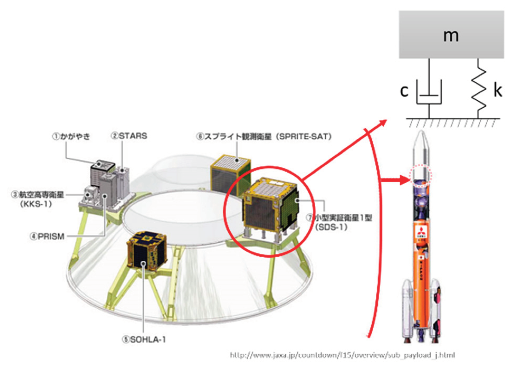
A satellite with which the fitting is carried out in a rocket is expressed in
Figure 1 [
2]. This is called a single-degree-of-freedom system (SDOF system). A mass of this SDOF system is suspended by a linear spring with a spring stiffness
k and a damper with a damping constant
c.
The natural angular frequency of this SDOF system, the natural angular frequency of a damping system and the damping ratio are
ωn,
ωd and
ζ respectively. Thus
ωn,
ωd and
ζ are expressed as [
3,
4,
5,
6]:
Since the natural angular frequency
ω can be indicated as
ω=2πf using the natural frequency
f,
fn and
fd are expressed as:
In the development of micro satellites, the value of ζ being used is 0.05 or below its value [
3,
4,
5,
6]. Therefore, the damping natural frequency
fd is almost the same as the non-damping natural frequency
fn. There are some approximate solutions of a non-damping vibration of a one-dimensional distribution mass system.
Figure 1.
Micro satellites in an H-IIA rocket and a Single-Degree-Of-Freedom system.
Figure 1.
Micro satellites in an H-IIA rocket and a Single-Degree-Of-Freedom system.
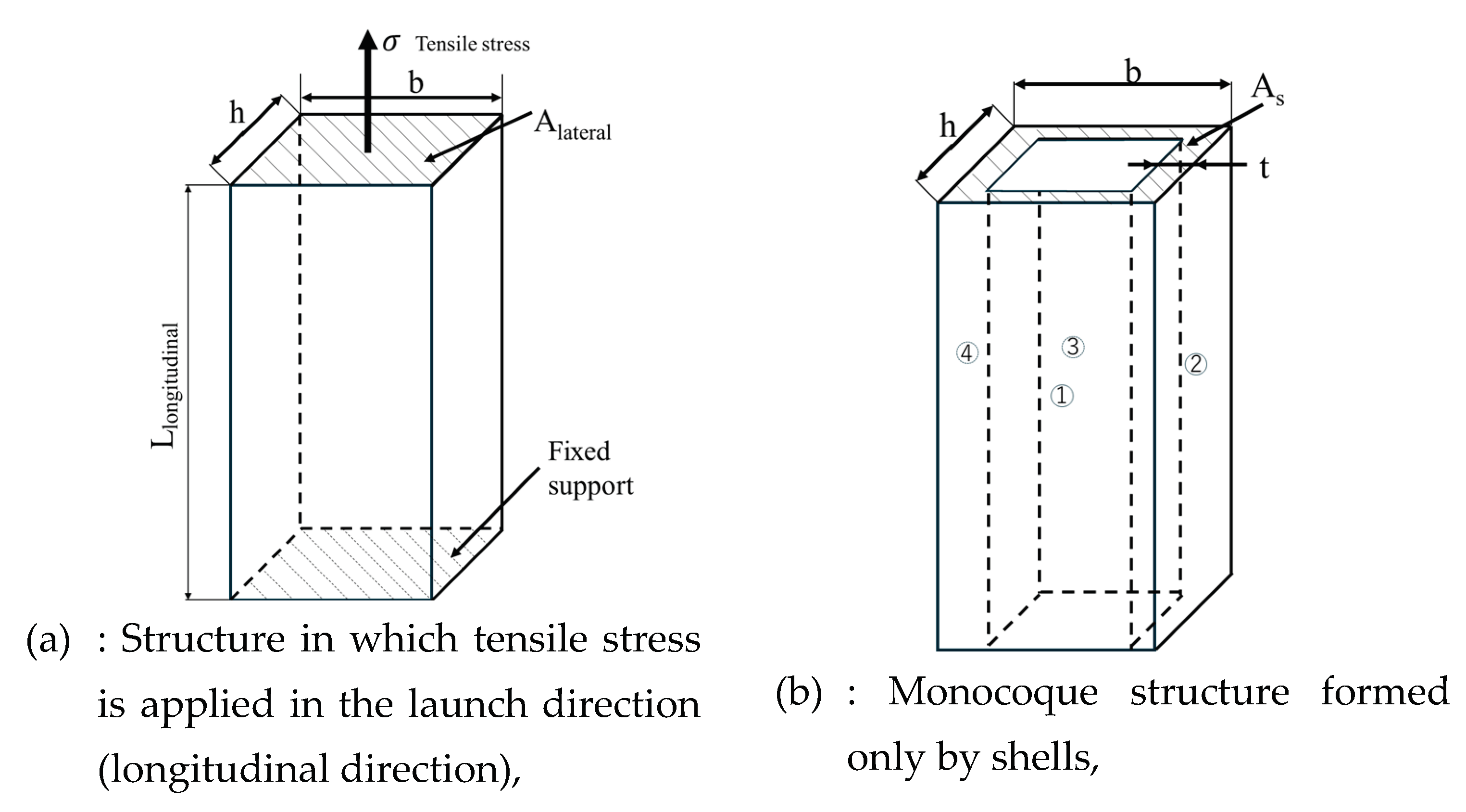
Figure 2 shows the outfitting of a small satellite with a rocket. This is a cantilever rod; the upper end of the rod is free to deflect but the lower end is rigidly clamped. When a tensile stress
σ applies at the free end of this rod in the ascent direction to launch (longitudinal direction), the rod has a cross-section
Alateral and a length
Llongitudinal. The elongation length of the rod, due to the applied tensile force
P, is denoted with
λ. The stiffness of the rod
k is defined with:
The minimum natural frequency of the longitudinal direction of the launching phase
fn,longitudinal can be estimated with:
Where
ms is the actual mass of the micro satellite. A micro satellite is composed of structural parts, bus equipment, mission equipment and so on. Therefore, when calculating the minimum natural frequency, it is necessary to estimate the Young's modulus of the satellite system,
Es, instead of the Young's modulus
Em of the main structure. When the volume of the entire satellite is
V, and the volume and Young's modulus of each component are
V1,
V2, ...
Vn,
E1,
E2, ...
En, the Young's modulus
Es of the entire satellite is:
However, the Young's modulus of other subsystems being very small compared with the elastic Young's modulus of structure material
Em, the elastic modulus of an actual satellite
Es is indicated by Eq. 6 in place of Eq.5 in this paper.
Here, Vs and V are the volumes of the satellite’s main structure and the entire satellite, respectively. In addition, Alateral and As are the lateral surface areas of the satellite and the lateral surface areas of the monocoque structure, respectively. Alateral is the value obtained by multiplying the width b and the depth h. The thickness t is the value when the satellite structure forms only four sides (①, ②, ③ and ④), and As is calculated from b, h and this thickness t.
Figure 2.
Satellite structure that looks like a rigidly clamped cantilever rod.
Figure 2.
Satellite structure that looks like a rigidly clamped cantilever rod.
When a load acts at the free end of the rod in
Figure 2 with a concentrated lateral forth
P in the orthogonal direction to launch (lateral direction): The longitudinal direction is the
x direction, and the lateral direction is the
y direction; the maximum deflection
y(x) occurs at the free end (
x=
L) as follows:
The stiffness
k is defined with Eq. 8:
Therefore, the minimum natural frequency in lateral direction can be calculated with:
However, if a bending moment and a uniformly distributed load are applied to the free end of this rod, 3 in Eq. 9 becomes 2 and 8, respectively. If the type of load acting on the free end is different, the number in the numerator will be different, so Eq. 9 is expressed as Eq. 10:
Where, n is a coefficient depending on the type of load. Similarly, when both a concentrated load acts on the free end and a uniformly distributed load acts on the entire beam, the n value is 11.
3. Experimental Verification of the Validity of a Simple Identification Method for the Minimum Natural Frequency
The Japan Aerospace Exploration Agency (JAXA) has been developing the new international space station (ISS) transfer vehicle "HTV-X" which will be launched by a new flagship rocket H3 [
7]. This HTV-X is the successor to the HTV, and is intended for in-orbit demonstrations in addition to resupplying supplies to the ISS [
7]. In the first HTV-X with the cube satellite (cubesat) release mission [
7], the first cubesat to be released from this HTV-X is Ten-Koh 2 (TK2) which the Okuyama Laboratory at Nihon University has been developing [
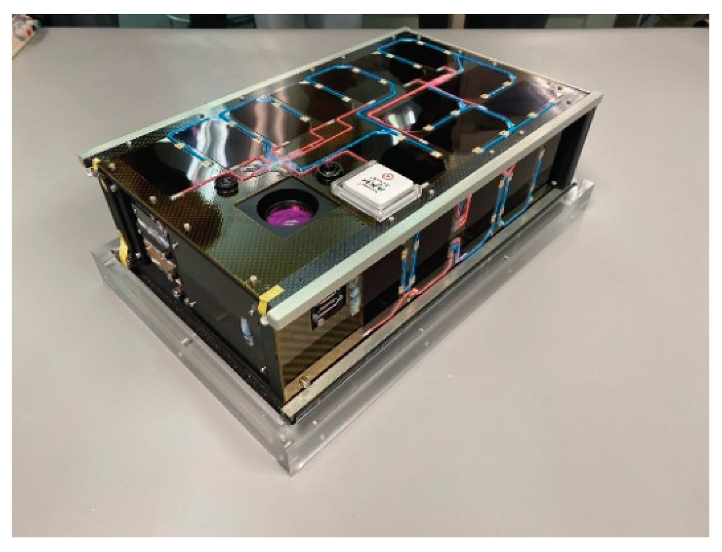
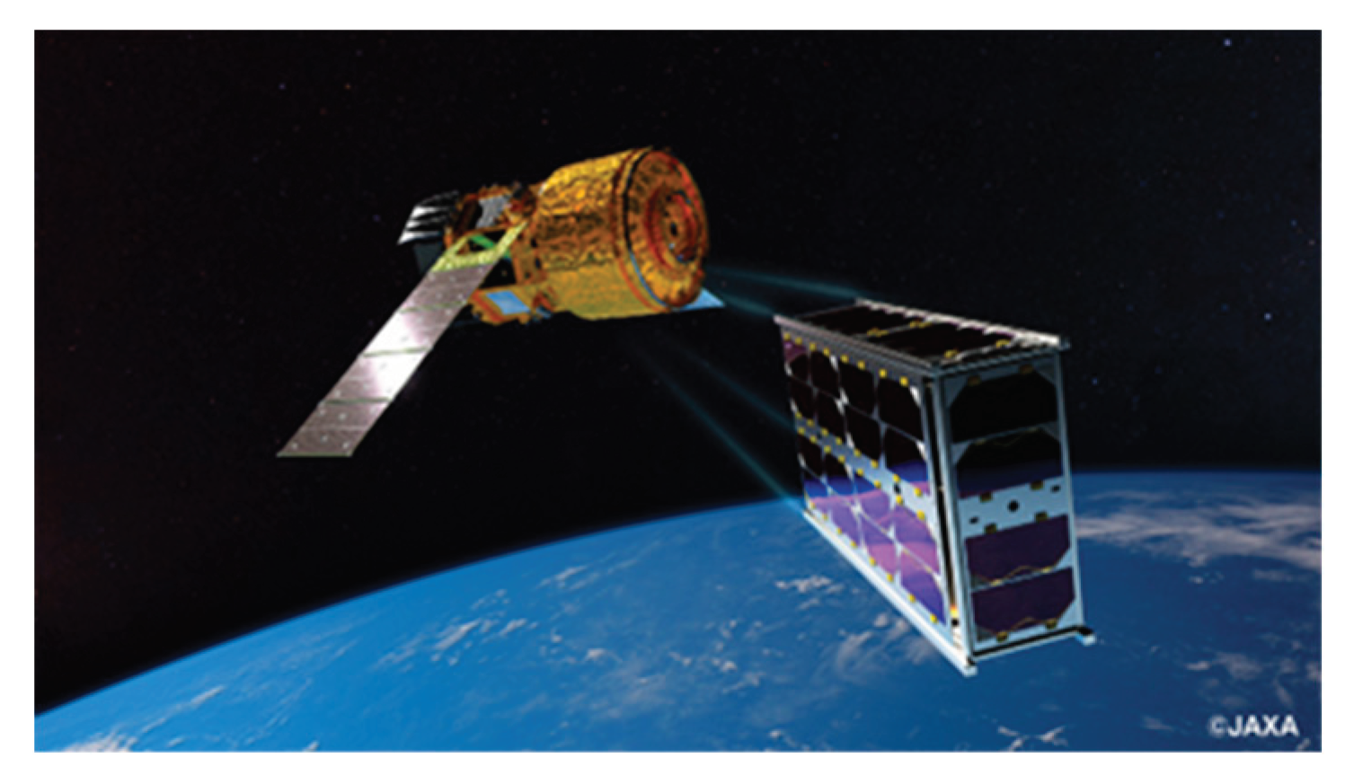
8]. TK2 is a cubesat with a size of wide-6U (366 mm x 226 mm x 100 mm) and a mass of approximately 6.8 kg. Both
Figure 3 and
Figure 4 show the appearances of TK2 which separated from HTV-X.
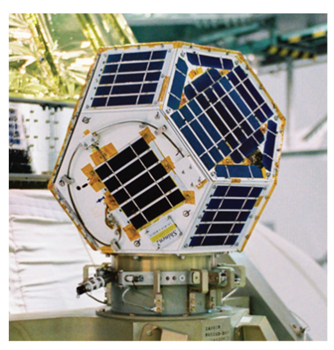
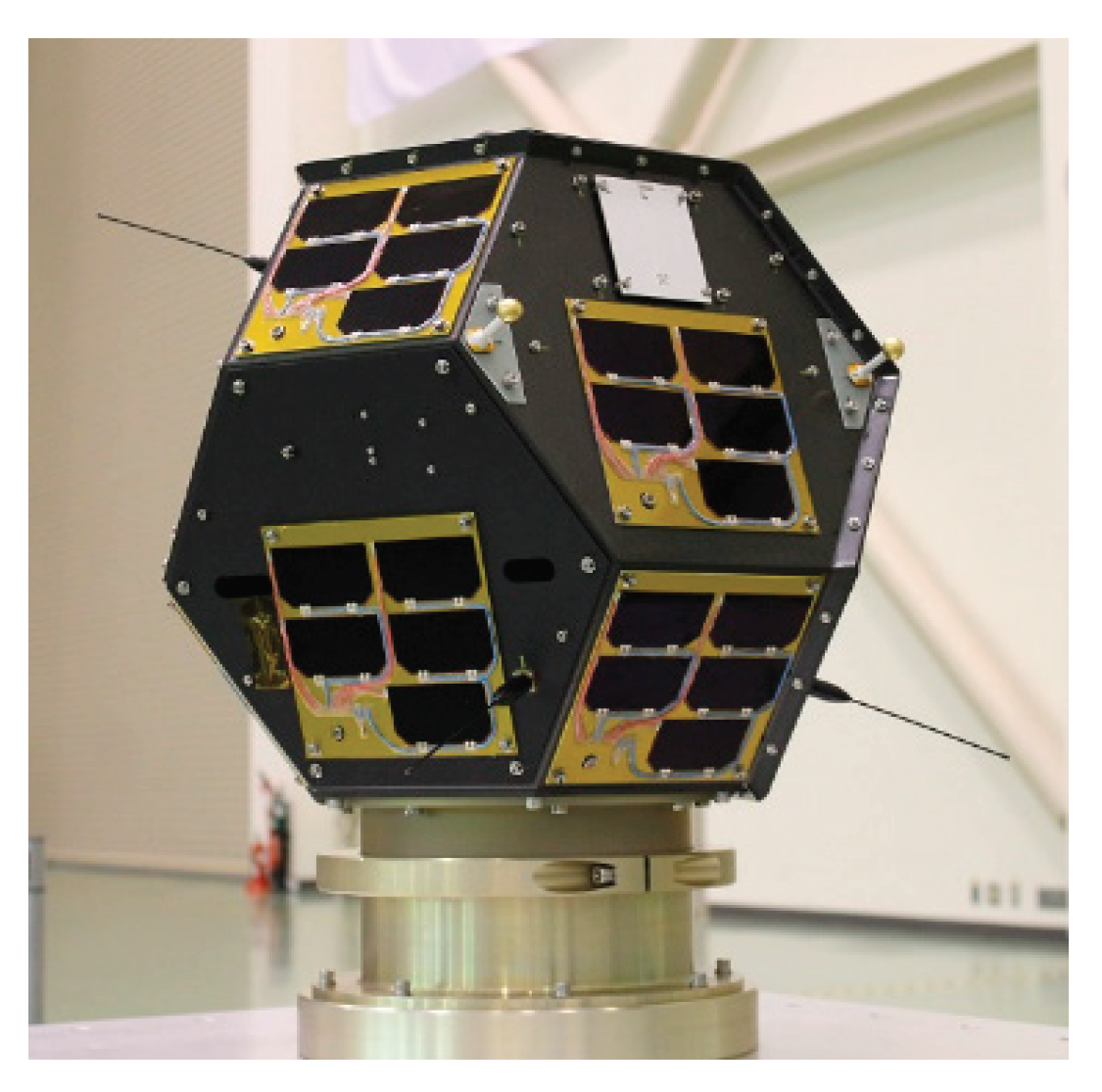
TK2 is the successor to Shin-en 2 (SE2) and Ten-Koh (TK1). SE2 was launched on December 3rd, 2014, by the H2A #26 as a Hayabusa2-sub-payload. It became the first small probe in the world to go beyond the lunar orbit and successfully conduct deep space exploration (measurement of high-energy charged particles) [
9,
10,
11]. TK1 was launched on October 29th, 2018, by the H2A #40 as a piggyback satellite of Ibuki 2 (GOSAT 2). TK1 was placed in a sun-synchronous quasi-return orbit at an altitude of 610 km. Overviews of SE2 and TK1 are shown in
Figure 5 and
Figure 6, respectively.
Usually, micro satellite design is performed through a procedure which designs and manufactures a Bread Board Model (BBM), an Engineering Model (EM) and a Flight Model (FM). A BBM, an EM, and a FM are developed in the preliminary design, the basic design and the critical design phases, and a FEM is used to thoroughly confirm whether the strength and stiffness requirements are satisfied in each phase. However, since a reliable FEM cannot be obtained at the initial stage of designing a BBM, it is important to establish a simple method to identify the natural frequency. In order to improve this simple identification method, we conducted tests using three micro satellite models. One is the FM of TK2, and another is the EM of Ten-Koh D (TKD). TKD is the successor to TK2 and is scheduled to be launched in 2026. The last one is a dummy satellite made of 100% aluminum alloy and was designed and developed by JAXA.
Figure 5.
Appearance of Shin-en 2 spacecraft.
Figure 5.
Appearance of Shin-en 2 spacecraft.
Figure 6.
Appearance of Ten-Koh spacecraft.
Figure 6.
Appearance of Ten-Koh spacecraft.
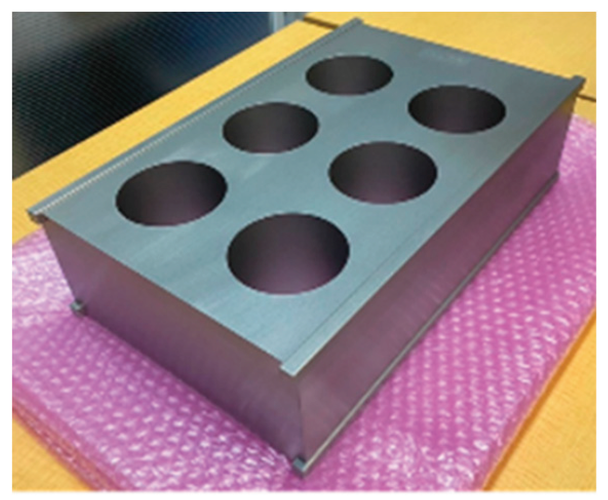
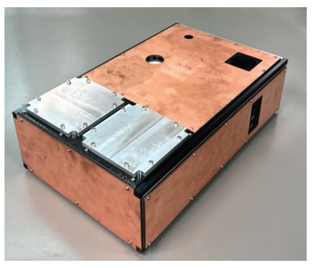
Table 1 shows the specifications of these three satellites, and overviews of aluminum alloy dummy satellites and the TKD’s EM are shown in
Figure 7 and
Figure 8, respectively. These three satellite models are equipped with rails that allow them to be jettisoned into space from a Small Satellite Orbital Deployer (SSOD) mechanism.
Table 1 also lists the sizes without this rail.
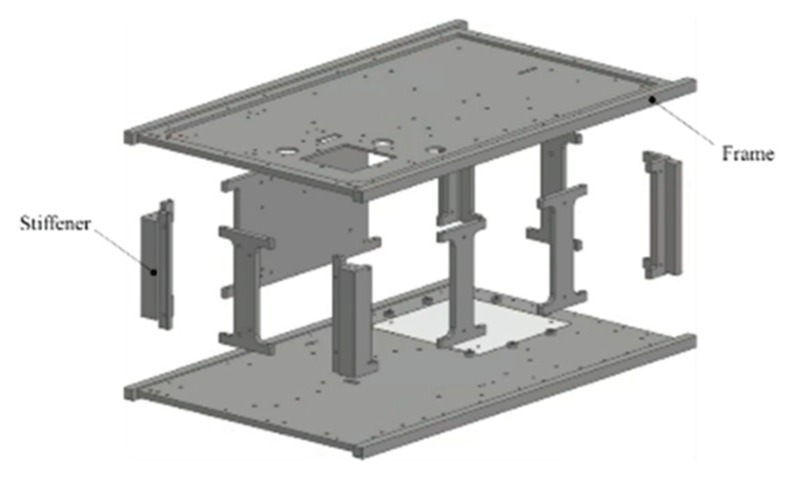
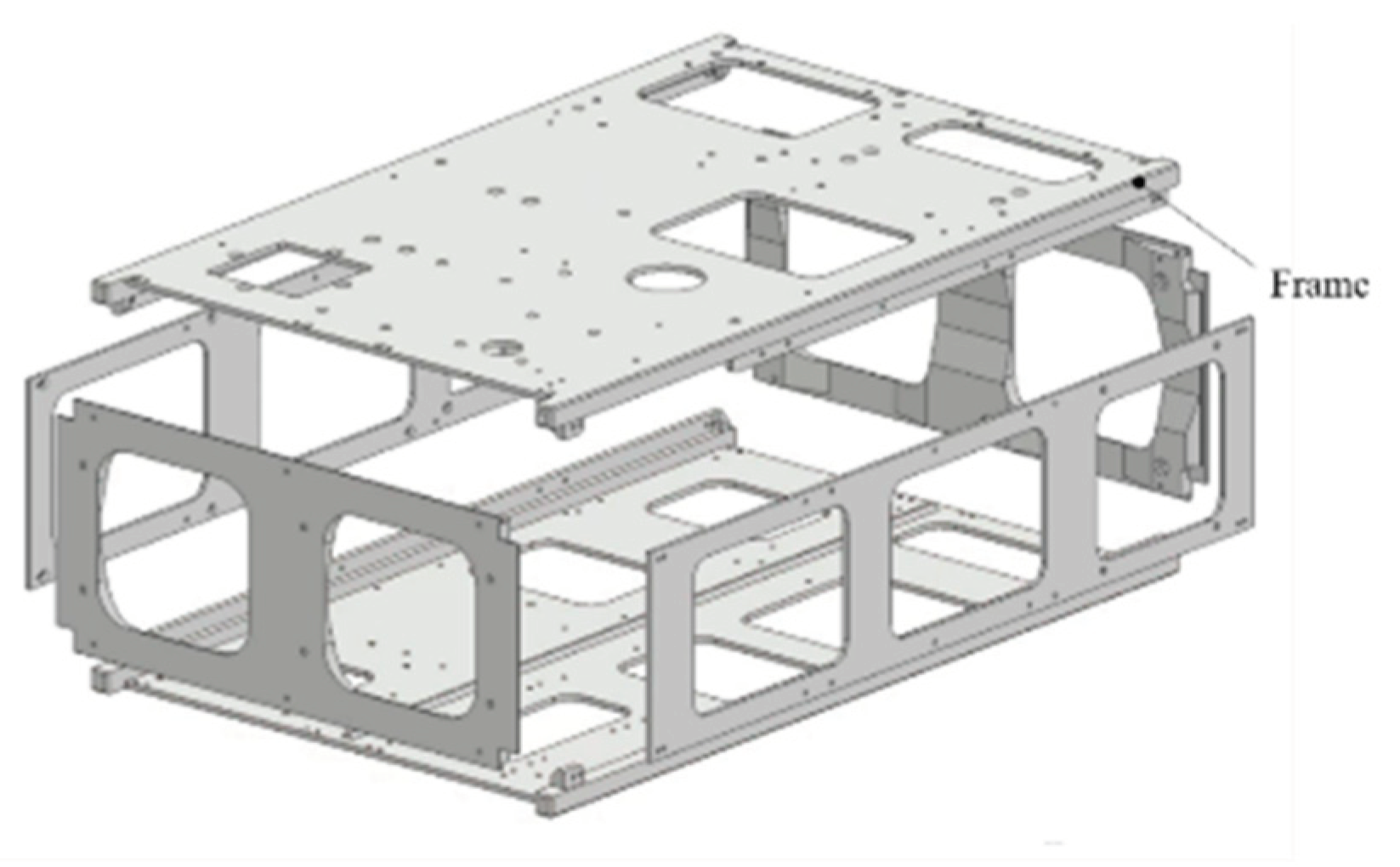
Furthermore, overviews of the primary structure of TK2 and TKD, which are made of aluminum alloy, are shown in
Figure 9 and
Figure 10, respectively. TK2 and TKD have large internal capacities and have been hollowed out to reduce weight. This type of shape is called a monocoque structure. Monocoque structures have excellent vibration resistance and are often used in the architectural field because they ensure strength. In the field of spacecraft development, this structural style is suitable for satellites because it not only maximizes the capacity of the satellite but also provides a surface for mounting components. The primary structure of TK2 consists of two frames and nine stiffeners. The primary structure of TKD consists of frames on all six sides.
The dummy satellite is also W6U type, and its size is the same as TK2 and TKD. The dummy satellite has six hollow holes with diameters of 73 mm, but it is made only of aluminum alloy.
Figure 9.
Primary structure of Ten-Koh 2’s FM.
Figure 9.
Primary structure of Ten-Koh 2’s FM.
Figure 10.
Primary structure of Ten-Koh D’s EM.
Figure 10.
Primary structure of Ten-Koh D’s EM.
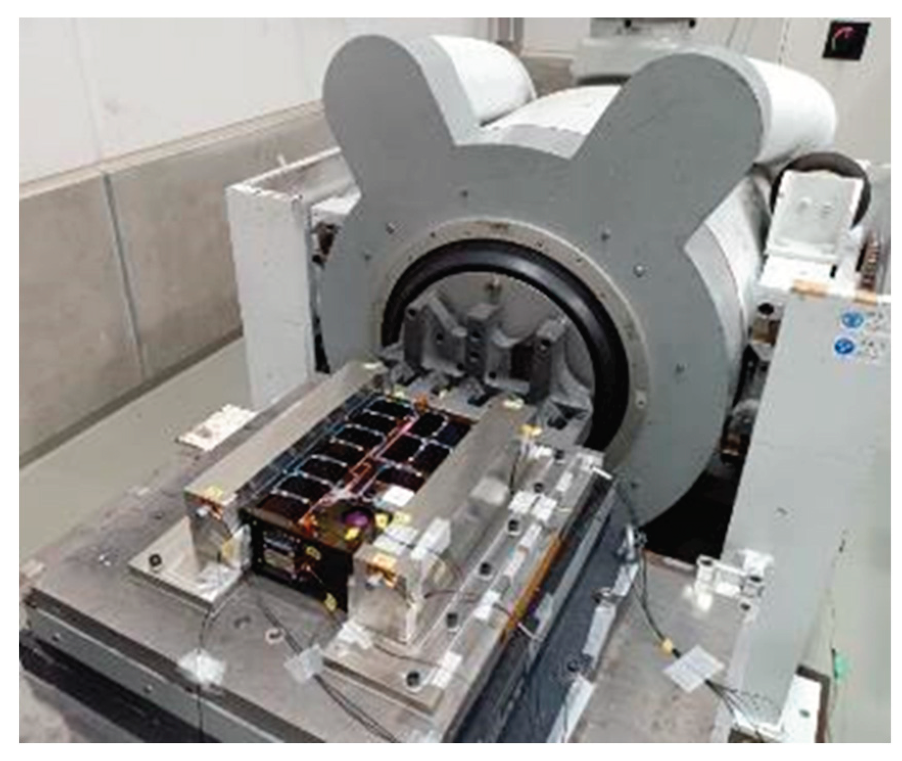
In order to acquire the minimum natural frequencies of micro satellites, vibration tests were carried out. These vibration tests were mainly done in the advanced technology center for environmental testing of IMV Corporation. i260/SA7M/HT10 (HT6) shown in
Figure 11 was used for the vibration tests [
11]. For this model, the maximum exciting force in a sine wave is 25,000N, the frequency range is up to 2,300Hz, the maximum random acceleration 700m/s
2 rms and the maximum payload mass is 138kg. The vibration tests were carried out based on the standard ISO 17025.
4. Vibration Test Results and Discussions
4.1. Natural Frequencies of Micro Satellites in Longitudinal Direction
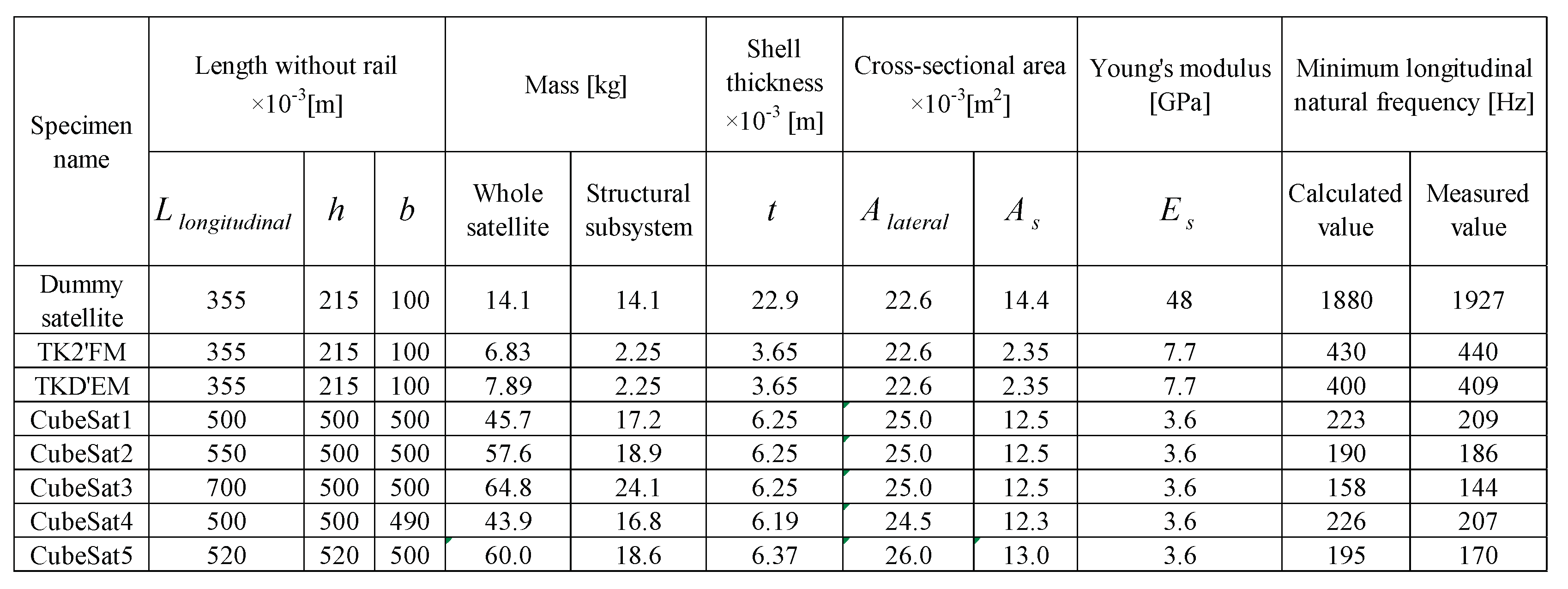
Vibration tests of the dummy satellite were conducted, and the test results of the natural frequencies obtained are shown in
Table 2. Generally, the aluminum alloys used for the main structure of spacecraft include A5052, A2024 (super duralumin), and A7075 (extra super duralumin), but the density and the Young's modulus of these three materials are 2680kg/m
3, 2770kg/m
3, and 2800kg/m
3 and 70.6GPa, 73.5GPa, and 71.6GPa, respectively. Since there is no significant difference in the density and the Young's modulus of these materials, the average values of 2,750 kg/m
3 and 72.0 GPa were used in this paper.
Table 3 also shows the calculation results of the natural frequency for a model without six holes with diameters of 73 mm. It shows the calculated values of the natural frequencies obtained using Eq. 4. Calculation results of the moment of inertia of area in the longitudinal and lateral directions for TK2 and TKD are shown in
Table 2 along with the measured values obtained in the vibration tests.
Table 2 also shows the calculation results of the natural frequency without the six holes with diameters of 73 mm.
The minimum natural frequencies of the dummy satellite calculated using Eq. 4 agreed relatively well with the measured values obtained in the vibration tests. In the case of the dummy satellite made of 100% aluminum alloy, we understand that the estimation method of Eq. 4 is valid.
Table 2 shows the vibration test results for TK2's FM and TKD's EM. The masses of TK2's FM and TKD's EM are 6.8 kg and 7.9 kg, respectively, and the mass of the aluminum alloy primary structure is 2.2 kg, which is the same value. When this primary structure forms only four sides as a monocoque structure, the thickness will be 3.6 mm, and the area calculated from this will be 2.3 x 10
-3 m
2. In addition, the longitudinal length is uniform at 346 mm. The Young's modulus was determined using Eq. 6, and these values are listed in Table 4. The longitudinal natural frequencies of TK2's FM and TKD's EM calculated from these are 433Hz and 403Hz, respectively, which agree well with the measured values of 440Hz and 409Hz. It can be confirmed from
Table 2 that the measured natural frequencies of TK2's FM and TKD's EM agree well with the values calculated using Eq. 4.
Table 2.
Minimum natural frequency in the launch direction (longitudinal direction).
Table 2.
Minimum natural frequency in the launch direction (longitudinal direction).
Okuyama et al. has conducted vibration tests to determine the natural frequencies using five various cube-shaped micro satellites; the masses range approximately 50 kg. These forms were cubes mostly and the lengths of one side ranged from approximately 50 cm. The specifications of the micro satellites used for this testing are shown in
Table 2 [
2]. Each micro satellite was vibrated in the Launch direction (longitudinal direction), and the minimum natural frequencies for each were measured. Okuyama et al. conducted vibration tests on the five cube-shaped micro satellites shown in
Table 2 and obtained the minimum natural frequencies in the longitudinal. The measurement results and the calculation results which are computed using Eq. 4 are shown in
Table 2. The measured values and the calculated values of both domains are in good agreement.
4.2. Natural Frequencies of Micro Satellites in Lateral Direction
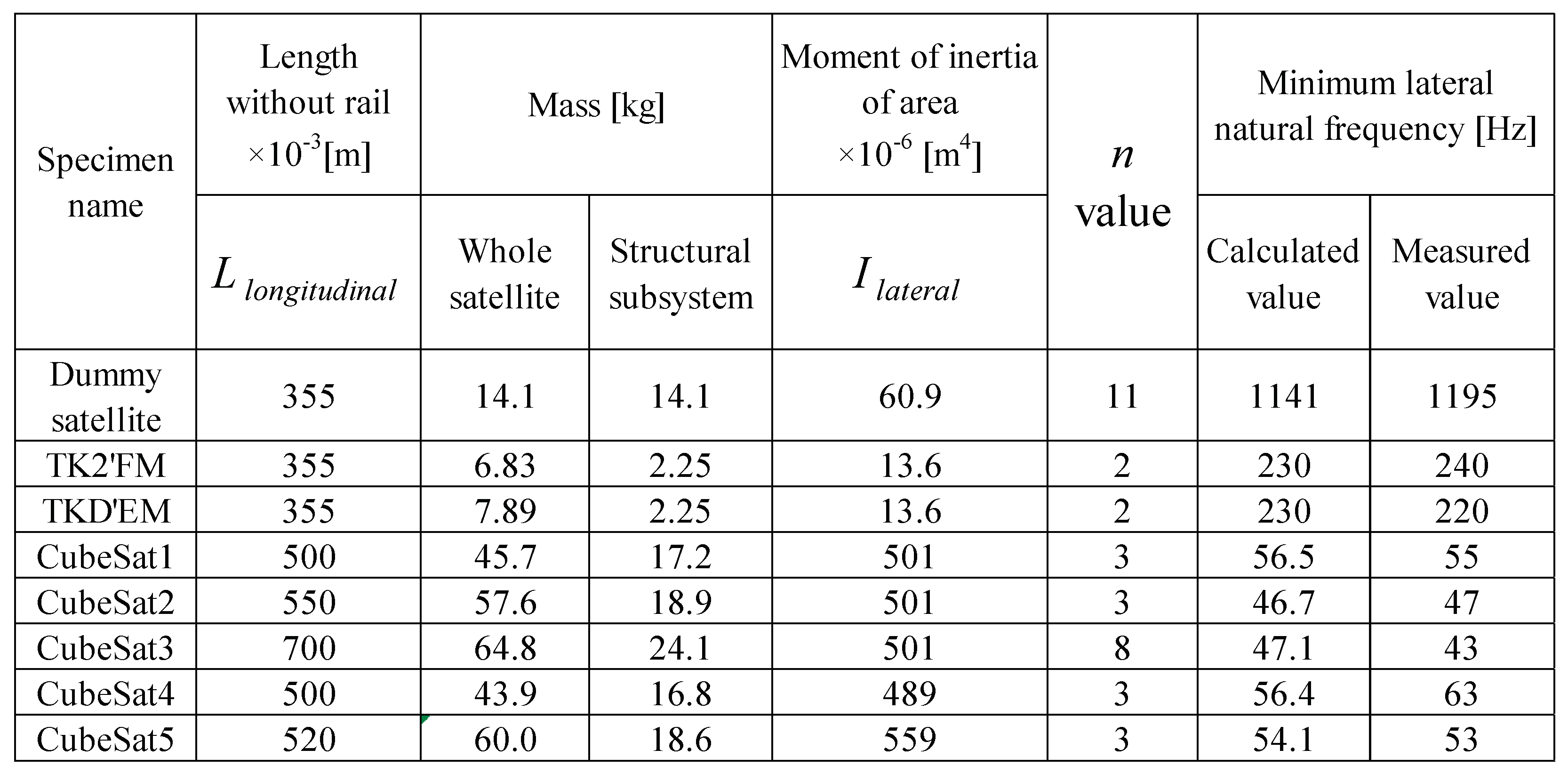
The minimum lateral natural frequency of the dummy satellite made of aluminum alloy with six holes with diameters of 73 mm was calculated using Eq. 10. The Young's modulus is the same value used for the longitudinal calculation. The moment of inertia of area was calculated assuming that the aluminum alloy primary structure forms all four sides of the monocoque structure, and these are listed in
Table 3. When 11 is entered as the
n value in Eq. 10, the minimum natural frequency in the lateral direction of this dummy satellite is 1141Hz, which roughly matches the measured value of 1195Hz. However, when using 2, 3 and 8 for the
n value, the calculated values are 487Hz, 596Hz and 973Hz, respectively, which are not the same values. When calculating the deflection of the free end of a fixedly supported cantilever beam when a uniformly distributed load is applied to the entire lateral direction, the
n value is 8.
Similarly, the minimum lateral natural frequencies of TK2's FM and TKD's EM using Eq. 10 are the same as 245Hz, which agrees well with the measured values of 240Hz and 229Hz. The n value used in this calculation is 2. This is the n value used to calculate the deflection when a bending moment load is applied to the free end of a fixedly supported cantilever beam.
Table 3.
Minimum natural frequency in the launch orthogonal direction (lateral direction).
Table 3.
Minimum natural frequency in the launch orthogonal direction (lateral direction).
Okuyama et al. obtained the minimum natural frequencies in the lateral direction of five cube-shaped micro satellites through vibration tests as well as in the longitudinal direction [
2].
Table 3 shows the calculated values of the minimum natural frequency obtained by inputting 3 as the
n value in Eq. 10. These values are in good agreement with the measured values. However, for a satellite with a relatively long longitudinal length of 70 cm, the calculated and measured values are not at the same level, 28 Hz and 43 Hz, respectively. From this, the calculated value of the minimum natural frequency obtained by inputting 8 to the n value in Eq. 10 is 47Hz, which is roughly the same as the measured value. When calculating the minimum natural frequency using Eq. 10, care should be taken in selecting the
n value.
5. Conclusions and discussion
Usually, the structural design of a micro satellite is developed using the internal stress analysis and the natural frequency analysis, which are based on a FEM. In an early stage of development, which has a FEM model of a satellite in the process of creation, presumption of the natural frequency of a satellite may be difficult. In this study, a simple method for determining the longitudinal and lateral minimum natural frequencies of the micro satellites during the ascent phase was clarified.
The minimum lateral natural frequency of the dummy satellite made of aluminum alloy with six holes with diameters of 73 mm was calculated using Eq. 4. This calculated value agreed relatively well with the measured values obtained in the vibration tests. The longitudinal natural frequencies of TK2's FM and TKD's EM calculated from these are 433Hz and 403Hz, respectively, which agree well with the measured values of 440Hz and 409Hz. The measured natural frequencies of TK2's FM and TKD's EM agree well with the values calculated using Eq. 4. Okuyama et al. has conducted vibration tests to determine the natural frequencies using five various cube-shaped micro satellites; the masses range approximately 50 kg. These forms were cubes mostly and the lengths of one side ranged from approximately 50 cm. The calculated results which are computed used Eq. 4 and the measured values are in good agreement.
When 11 is entered as the n value in Eq. 10, the minimum natural frequency in the lateral direction of the dummy satellite is 1052Hz, which roughly matches the measured value of 1141Hz. Similarly, the minimum lateral natural frequencies of TK2's FM and TKD's EM using Eq. 10 are the same as 245Hz, which agrees well with the measured values of 240Hz and 229Hz. The n value used in this calculation is 2. The measured minimum natural frequencies in the lateral direction of five various cube-shaped micro satellites weighing approximately 50 kg are in good agreement with the calculated values by inputting 3 as the n value in Eq. 10. However, for the satellite with a relatively long longitudinal length of 70 cm, the calculated and measured values are not at the same level, 28 Hz and 43 Hz, respectively. From this, the calculated value of the minimum natural frequency obtained by inputting 8 to the n value in Eq. 10 is 47Hz, which is roughly the same as the measured value. When calculating the minimum natural frequency using Eq. 10, care should be taken in selecting the n value.
In this study, we used the dummy satellite made of 100% aluminum alloy, a W6U type small satellite scheduled to be actually launched on an H3 rocket, and 50 kg class satellites to develop a simple identification method for the minimum natural frequency in the longitudinal and lateral directions during ascent phase. Since the values identified using this simple method generally agreed with the measured values, this identification method is considered to be generally valid.
Acknowledgments
The Ten-Koh 2 project was carried out under the guidance of JAXA, and the aluminum alloy dummy satellite used in this research was designed and manufactured by JAXA. The Ten-Koh 2 project was conducted under a joint research agreement with Space BD Corporation. In addition, the Ten-Koh 2 project was also carried out in cooperation with Eto Seisakusho Co., Ltd. and Denken Co., Ltd. in Oita Prefecture, and Hibiki Seiki Co., Ltd. in Yamaguchi Prefecture. The Ten-Koh 2 project was funded by the Nihon University College of Science and Technology's Research Institute for Advanced Research Grants. We would like to express our gratitude to all those involved.
References
- Japan Aerospace Exploration Agency, User's manual of H-IIA rocket (in Japanese), JERG-4-011A, 2015.
- Kei-ichi Okuyama, Shigeru Hibino, Misuzu Matsuoka and Aleksander Lidtke, A Modification of an Estimation Method of the Natural Frequency of a Cubic Form Micro Satellite, International Journal of Research Granthaalayah, Vol.7 (Iss.7), pp. 121 -131, July 2018,ISSN. 2350-0530(O), ISSN-2394-3629(P). [CrossRef]
- Japan Aerospace Exploration Agency, Structural design standard (in Japanese), JERG-2-320A, 2011.
- M. J. Casiano, Extracting Damping Ratio from Dynamic Data and Numerical Solutions, NASA TM-2016-218227, 2016.
- L. E. Kinsler, A. R. Frey, A. B. Coppens and J. V. Sanders, Fundamentals of Acoustics, John Wiley & Sons, 4th edition, 2000.
- J. JaapWijker, Spacecraft Structures, Springer, 2008 edition, 2008.
- Norimasa ITO, Hiroshi SASAKI, Development Status of New Space Station Transfer Vehicle (HTV-X), Council for Science and Technology, Research Planning and Evaluation Subcommittee, Space Development and Utilization Subcommittee (in Japanese), 2021.
- Kei-Ichi OKUYAMA, Rafael Armando RODRIGUEZ LEON, Isai FAJARDO TAPIA and Ten-Koh 2 Team, Completion of the Development of Ten-Koh 2 Spacecraft, 33th International Symposium on Space Technology and Science, Proceedings, Kurume, Japan, 2024.
- Fumito KUROIWA, Kei-Ichi OKUYAMA, Masanori NISHIO, Hiroki MORITA, Bianca A. SZASZ, Sidi Ahmed BENDOUKHA, P.B. SAGANTI and S.D. HOLLAND, A Design Method of an Autonomous Control System for a Deep-Space Probe, Transactions of the JSASS Aeronautical and Space Sciences, JSASS Aerospace Tech Japan, 2016 [Vol.14,No. Ists30], pp. Pf_105-Pf_112. [CrossRef]
- Jesus Gonzalez-Llorente, Aleksander A. Lidtke, Ken Hatanaka, Ryo Kawauchi and Kei-Ichi Okuyama: Solar Module Integrated Converters as Power Generator in Small Spacecrafts: Design and Verification Approach. Aerospace, 2019 [Vol.6, No.5], pp. 1-23. [CrossRef]
- Isai Fajardo, Aleksander A. Lidtke, Sidi Ahmed Bendoukha, Jesus Gonzalez-Llorente, Rafael Rodríguez, Rigoberto Morales, Dmytro Faizullin, Misuzu Matsuoka, Naoya Urakami, Ryo Kawauchi, Masayuki Miyazaki, Naofumi Yamagata, Ken Hatanaka, Farhan Abdullah, Juan J. Rojas, Mohamed Elhady Keshk, Kiruki Cosmas, Tuguldur Ulambayar, Premkumar Saganti, Doug Holland, Tsvetan Dachev, Sean Tuttle, Roger Dudziak and Kei-ichi Okuyama: Design, Implementation, and Operation of a Small Satellite Mission to Explore the Space Weather Effects in Leo, Aerospace, 2019 [Vol.6, No.10], pp. 1-38. [CrossRef]
- IMV Corporation, User's manual of vibration testing system (Model i260/SA7M/HT10 (HT6), 2018.
|
Disclaimer/Publisher’s Note: The statements, opinions and data contained in all publications are solely those of the individual author(s) and contributor(s) and not of MDPI and/or the editor(s). MDPI and/or the editor(s) disclaim responsibility for any injury to people or property resulting from any ideas, methods, instructions or products referred to in the content. |
© 2024 by the authors. Licensee MDPI, Basel, Switzerland. This article is an open access article distributed under the terms and conditions of the Creative Commons Attribution (CC BY) license (http://creativecommons.org/licenses/by/4.0/).
