1. Introduction
Optical metasurfaces have drawn great attention in the past decades due to their distinctive properties including perfect absorption [
1,
2], negative refractive index [
3], and phase engineering [
4]. A large variety of metasurface devices have been demonstrated such as perfect absorbers [
5], color filters [
6], and wavefront manipulators [
7,
8]. Due to the advantage of compact size, the optical metasurface devices show great potential in applications for micro- and nano-optical systems [
9]. In the field of color filters, traditional methods with pigments and dyes [
10] suffer from fading, low spatial resolution, and environmental pollution, which hinders their application in micro-optical systems or applications requiring high spatial resolution. The structural color based on metasurfaces outperforms the traditional dye and pigment coloration due to the advantages in non-fading, high spatial resolution, and environmental friendliness. In the past decades, the structural color devices based on multi-layer structure, dielectric nanostructure, and metallic nanostructure have been extensively studied to exhibit excellent color property and sub-wavelength spatial resolution [
6,
11,
12]. However, the response of the metasurface is usually fixed after being fabricated, which limits their potential in application to active optical systems. In order to make the metasurface dynamic, active materials are usually employed in the structures, such as electro-optical materials [
13], electrochromic materials [
14,
15], phase-change materials [
16,
17], semiconductors [
18], liquid crystals [
19,
20,
21], electro-chemistry [
22,
23], and MEMS [
24]. The underlying physics of the active material-based dynamic structural color is the strong dependence of the optical response of the nanostructures on the size parameters and the optical properties of the constituent structures and materials.
In addition to modulating the property of the constituent materials, the tailoring of the incidence or output light polarization also enables the tunability of the anisotropic metasurfaces. Most of the linear polarization angle tuning offers dual-mode variation to realize bi-functional tunability, such as two colors, and bi-information encoding [
25,
26,
27,
28]. Full-color generation realized by simply varying the polarization angle of the incident linearly-polarized white light is rarely seen. Several studies achieved rich color generation using the blocks and apertures with long axes aligning in different directions [
29,
30]. Polarization-controlled full-color tunable plasmonic pixels were reported consisting of three different types of color modules corresponding to three subtractive primary colors in reflection [
31]. The full-color generation in both reflection and transmission modes at the same time using the same structure has not been reported yet.
Here, we demonstrate, for the first time, bi-directional full-color generation using the same metasurface based on simple polarization-angle variation of the incident linearly-polarized white light, without any active materials involved. The full-color metasurface is obtained through the module design to incorporate multiple modules in the metasurface unit cell. In this metasurface, the modules in three directions are included, and as a result, optical modes corresponding to each module can be selectively excited by the linearly-polarized light and full color can be generated in both reflective and transmissive modes using the same structure. The potential of the proposed structural color filter method for encoding is demonstrated by integrating three pieces of optical information into one device. We have designed three-channel information in one metasurface and successfully decoded the information on each channel by varying the polarization angle of the incident linearly-polarized light. The proposed structural coloration method has great potential in dynamic color display, anti-counterfeiting, and optical information encoding.
2. Results and Discussions
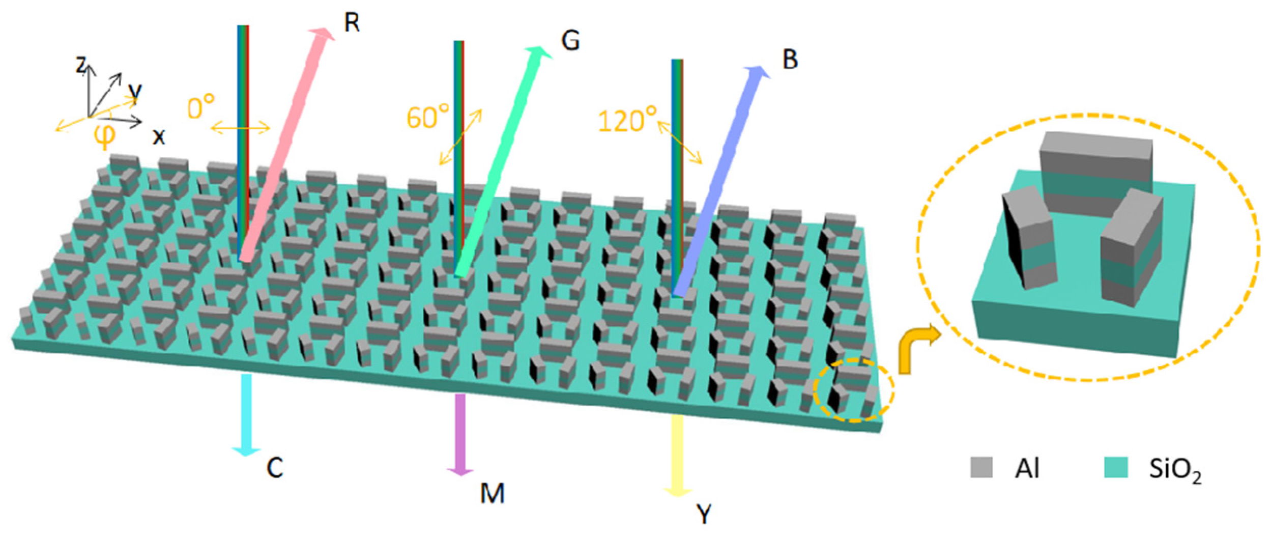
In order to realize full-color generation by varying the linear-polarization angle of the incident white light, a metasurface comprised of three-module units was designed as shown in
Figure 1. Due to the polarization-dependent optical responses, the module exhibits polarization-dependent structural colors. The three modules are positioned in particular directions in the
x-y plane as shown in the enlarged plot of the unit cell in
Figure 1. And in both the reflection and transmission modes, various color generations can be achieved when the linearly polarized white light with varying polarization angles illuminates the metasurface normally from above. The additive colors and the subtractive colors are generated in reflection and transmission, respectively.
To evaluate the optical response of the plasmonic metasurface, the finite-difference time-domain method is adopted to perform the electromagnetic modeling of the metasurface. The parameters of the optical performance of the materials, Al and SiO
2, can be referred to Ref. [
32]. First, the optical response of the metasurface with the unit cell consisting of one module is studied. The module is a rectangular post consisting of a three-layer structure (metal/dielectric/metal). Due to the outstanding plasmonic property in the visible regime, Al is selected as the plasmonic material. And transparent SiO
2 is adopted as the dielectric layer and the substrate. The long axis of the module is positioned along the x-axis direction. The unit cells are distributed in a square array. The length of the module is changed for manipulating the optical response spectra when the period is set to 360 nm, the width of the module 60 nm, and the thickness of each layer 50 nm. Size-dependent spectra can be seen in both reflection and transmission spectra in
Figure 2. When the length of the module increases, the reflectance peak and the transmission dip redshift to the long wavelengths in the visible regime with the x-polarization white light incidence, as shown in
Figure 2a,b. With the y-polarization white light incidence, there is no reflectance peak or transmission dip in the spectra where the reflectance is low throughout the visible regime to exhibit a ‘dark’ state in reflection and the transmittance is high to exhibit a ‘bright’ state in transmission as shown in
Figure 2c,d. As such, the rectangular module acts as a polarization-dependent structural color filter in both the reflection and transmission modes. The peak and the dip positions in the spectra can be designed by changing the size of the module.
Due to the fact that the full color can be generated by mixing three primary colors, the three-module metasurface is designed. In the metasurface in
Figure 1, the three modules are positioned with angles of 0°, 75° and 120° respectively with respect to the
x-axis direction for consideration of mixing three primary colors. Therefore, the modes corresponding to the long axis of the modules can be excited selectively by varying the linear polarization angle of the white light incidence. The reflectance spectra with respect to the incident polarization angle are calculated and shown in
Figure 3(a). As expected, the three modes in the structure are respectively excited with respect to the polarization angle of incident linearly-polarized light. As a result, there are three peaks at different wavelength ranges in the reflection spectra with respect to varying polarization angles. In order to estimate the perceived color, the corresponding color is described in the CIE 1931 color space with a D65 standard illumination [
23]. The CIE XYZ tristimulus values corresponding to the optical response spectra (reflection or transmission) are calculated as [
33].
where
k is a normalization factor,
is the spectral energy distribution of the reference light, and
is the far field reflectance or transmittance spectrum obtained from the designed metasurface under illumination. The
,
and
are the CIE 1931 standard color-matching functions.
33 The chromaticity values
x and
y are then normalized as
and
, which fall between 0 and 1, to represent the colors in the CIE 1931 color space as shown in Figures 3c and 3f, respectively.
The predicted color of a certain spectrum under illumination corresponds to a point in the CIE 1931 color space. As the polarization angle of the incident linearly-polarized light varies, the color changes as well. The routine of the color variation of the metasurface circles the chromatic color point (denoted as the asterisk symbol shown in
Figure 3c,f) in the CIE 1931 color space, which indicates the full-color generation from the metasurface. As the polarization angle varies from 0° to 180° counterclockwise, the color evolves from red region to green region, and from green region to blue region as seen in
Figure 3c. As shown in
Figure 3b, three reflectance spectra corresponding to the polarization angles 0°, 60°, and 120° are plotted, where the three distinct peaks correspond to the red, green, and blue colors, respectively.
To evaluate the transmission performance of the metasurface, the transmittance spectra are also calculated as depicted in
Figure 3d. There are three transmission dips in the spectra with respect to varying polarization angles of the incident linearly-polarized white light. Contrary to the reflection case, the transmission dips in spectra of the transmission case generated subtractive colors. In the CIE 1931 color space, the color transmitted from the device evolves from the cyan region to the magenta region, and from the magenta region to the yellow region as the polarization angle of the incident linearly polarized light varies from 0° to 180° counterclockwise as seen in
Figure 3f. The transmitted colors circle the chromatic color point in the CIE 1931 color space. The transmission spectra corresponding to the polarization angles 0°, 60°, and 120° are plotted in
Figure 3e. There are three transmission dips located at different wavelengths corresponding to varying polarization angles of the linearly-polarized incidence. To describe the perceived colors, they are corresponding to cyan, magenta, and yellow colors, respectively. As a result, full subtractive colors can be generated from the metasurface in the transmission mode. In summary, the full-color generation in both reflection and transmission can be successfully realized by the designed metasurface with respect to the varying polarization angle of the incident linearly polarized white light of D65 illumination. Additive full colors are generated in reflection and subtractive full colors are generated in transmission.
The bi-directional color generation by the metasurface originates from the optical property of the modules. The in-phase plasmonic mode in the metal/dielectric/metal nanostructures can be excited to generate rich colors [
34]. Due to the anisotropy of the module, the corresponding plasmonic mode can be excited by the linearly-polarized light with polarization along the long axis of the module. When the incident linearly-polarized light polarizes perpendicular to the long axis of the module, no resonance resides in the visible regime due to the small width of the module. To interpret the underlying physics of the polarization-dependent structural colors, the electromagnetic field in the metasurface is calculated. Due to the anisotropy of the modules, the resonance in each module can be selectively excited by the linearly-polarized light. As the polarization angle varies, the electric field distributions of the nanostructures in x-y plane are illustrated in
Figure 4a–c. The enhanced and localized electric field can be seen around the module when the incident light polarization is parallel to the orientation of the module at the plasmonic wavelength. When the incident polarization angle is 0°, the plasmonic resonance in the 0°-alignment module is excited at wavelength of 659.4 nm. When the incident polarization angle is 60°, the plasmonic resonance in the 75°-alignment module is excited at wavelength of 518.6 nm. And when the incident polarization angle is 120°, the plasmonic resonance in the 120°-alignment module is excited at wavelength of 444.2 nm. Due to the plasmonic resonance in the modules, enhanced reflection and reduced transmission are generated at the plasmonic wavelengths. The tri-layer structure generates a peak in the reflection spectrum and a dip in the transmission spectrum when the incident linearly-polarized light polarizes parallel to the long axis of a certain module. The polarization-dependent optical responses of the module enable the polarization-dependent structural colors to generate additive colors in reflection and subtractive colors in transmission, respectively. Based on the polarization-tunable optical response of the tri-layer module, polarization-tunable structural colors of interest can be customized by the module design method to choose different module sizes and orientations in the metasurface.
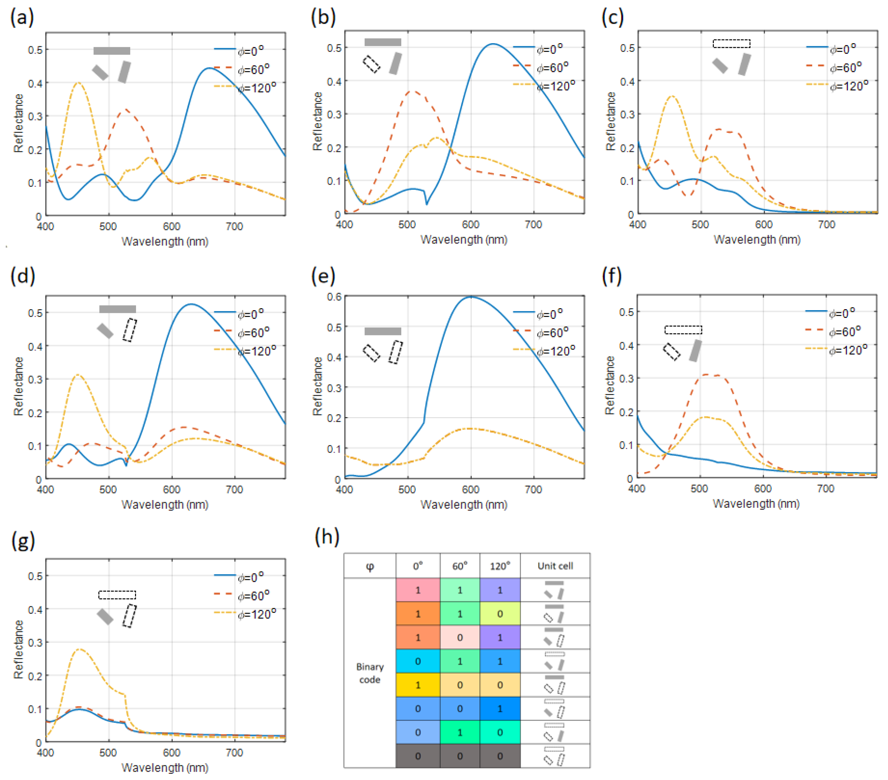
Based on the polarization-selectivity of the mode excitation of each module, the metasurface consisting of modules can be designed to manipulate the output. When three modules are included in the unit cell, the reflection spectra are shown in
Figure 5a. Three reflection peaks are found at varying polarization angles of the incident light. When the combinations of the modules are changed in the unit cell, the reflection spectra are shown in
Figure 5b–g. At first, the three-module unit cell is varied to a two-module unit cell. The corresponding reflectance spectra are shown in
Figure 5b–d. When the two modules along the direction of 0° and 75° are utilized, reflectance peaks at the long wavelength side and in the range of 500~550nm appear in the reflectance spectra, respectively. When the two modules along the direction of 75° and 120° are employed, reflectance peaks in the range of 500~550nm and at the short-wavelength side appear in the reflectance spectra, respectively. Similarly, when the two modules along the direction of 0° and 120° are used, reflectance peaks at the long wavelength side and short wavelength side appear in the reflectance spectra, respectively. Further, when there is only one module in the unit cell, the reflectance peaks corresponding to the polarization angles of the incident light coinciding with the module directions show up, respectively, as shown in
Figure 5e–g. In particular, the reflectance peak may also exist when the polarization angles are not along with the module directions as a result of non-orthogonal relation between the polarization angles and the module orientations. Some inspirations can be drawn from the above results. With the existence of the module in the 0° direction, there are reflectance peaks at the long wavelength side for all cases with the 0° polarization incidence, which leads to a similar color from red to yellow for the unit cells. For unit cells with the module in the 75° direction, there are peaks at the wavelength range from 500 nm to 550 nm with the 60° polarization incidence which leads to similar green color for unit cells. And for unit cells with the module in 120° direction, there are peaks at the wavelength below 450nm with the 120° polarization incidence which leads to similar colors from blue to purple. As a result, structures with different unit cells can be distinguished by the linearly polarized light via varying polarization angles of the incident linearly-polarized white light and examining the perceived color in the reflection configuration. As shown in
Figure 5h, the unit cell structures and the corresponding colors are listed as a look-up table for the information encoding. The result indicates that the polarization-dependent information can be encoded onto the metasurface.
For the transmission configuration, the transmittance spectra of the various unit cell structures are plotted in
Figure 6a–g, where subtractive structural colors are generated by the metasurface. With the existence of the module in the 0° direction in the metasurface, there are transmission dips at the long wavelength side for all cases with the 0° polarization incidence, which leads to a similar color from cyan to blue for the unit cells. For the unit cells with the module in 75° orientation, there are transmission dips at the wavelength range from 500 nm to 550 nm with the 60° polarization incidence, which leads to similar magenta color for unit cells. And for the unit cells with the module in 120° orientation, there are dips at the wavelength region around 450nm with the 120° polarization incidence, which leads to similar yellow colors. The output of the structures with different unit cells can be distinguished by illuminating linearly polarized white light via varying polarization angles and examining the perceived color in transmission. The binary code combinations, the corresponding unit cell structures and transmission colors are listed in
Figure 6h. Therefore, the existence of certain modules can be visualized by the perceived colors in transmission. The results are interesting, and indicate that the polarization-dependent binary information can be encoded to the plasmonic metasurface and decoded by varying the polarization state of the incident light to examine the colors.
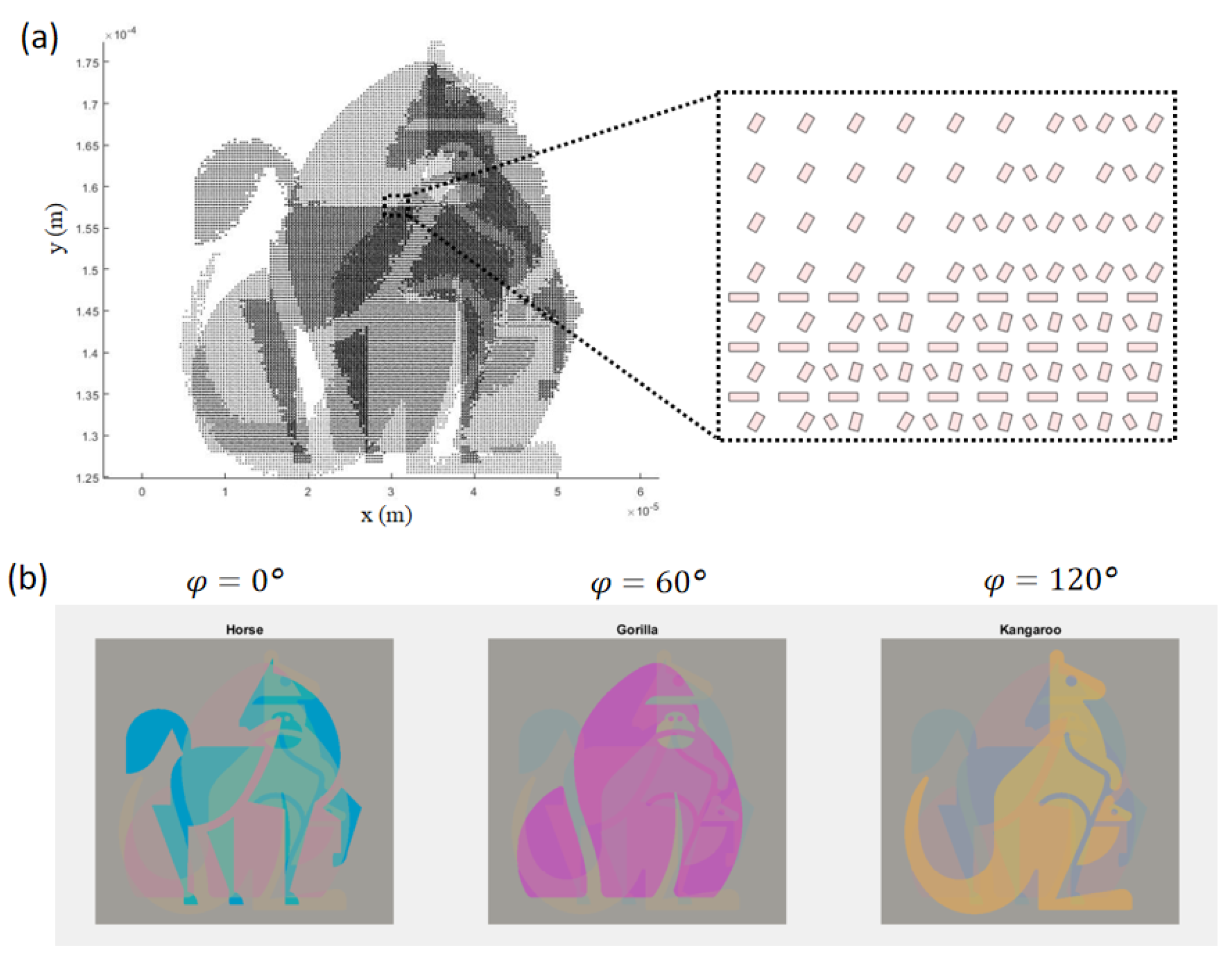
The polarization-dependent color generation method can be adopted in the polarization-angle enabled information display, anti-counterfeiting, and optical information encoding in both reflection and transmission configurations. According to the polarization-dependent color modulation, different optical information can be encoded onto the metasurface corresponding to varying incident linear polarized light. Three pieces of binary information (e.g., pixels of 2D pictures) can be encoded into one unit cell and the corresponding information can be decoded by tailoring the input linear polarization angle. Based on the look-up table in transmission, we first designed a metasurface with three information channels with respect to the incidence polarization angles of 0°, 60°, and 120°, each of which contains an image of a certain animal. As shown in
Figure 7a, the metasurface is designed based on the look-up table in
Figure 6h and the animal image. In the enlarged plot, we can see different unit cells at different locations corresponding to the encoding information. With the normal incidence of un-polarized white light illumination, the information of the three channels of animal images overlaps and cannot be distinguished. In contrast, with the linearly polarized white light illumination, the optical images in each channel can be obtained as shown in
Figure 7b. With different incident polarization angles, the main color of the optical image differs. With the 0° polarization incidence, the optical mode of the module along the 0° direction is excited and outperforms the other modes in the unit cell, so that the perceived color of the corresponding unit cells is in the region of cyan and the decoded image is an image of a horse in the color of cyan and blue. Similarly, the unit cells with the module along the 75° direction under the 60° polarization incidence generate the color of magenta, and the decoded image is an image of a gorilla in the color of magenta. The unit cells including the module along the 120° direction under the 120° polarization incidence generate a color of yellow, and the decoded image is an image of a kangaroo in the color of yellow. As a result, three images of animals can be successfully encoded to one metasurface and decoded in transmission by varying the polarization angle of the linearly-polarized incident white light.
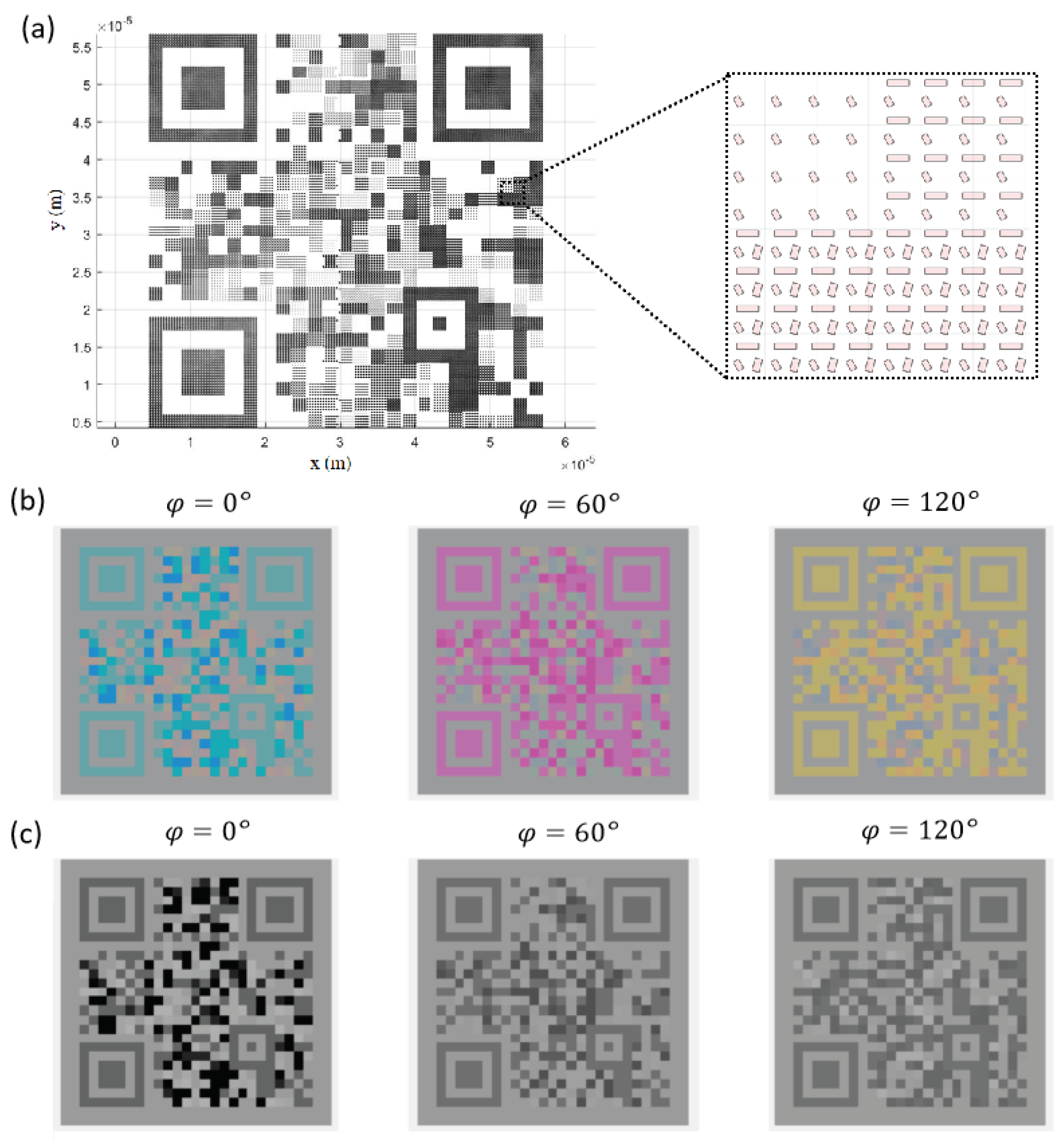
As a second example, we designed a plasmonic metasurface containing three binary Quick Responsive (QR) Codes and examined them in a transmission configuration. The QR code is a two-dimensional binary information matrix and can include abundant information. The QR codes were designed to contain information of the ‘Zhejiang Lab’, ‘Metasurface’, and ‘Color Filter’, respectively. Using the look-up table, multiple pieces of binary information can be encoded in the metasurface as shown in the list in
Figure 6h. The binary pixels of the QR codes corresponding to various unit cells were encoded into the nanostructures. The pattern is designed as shown in
Figure 8a. Different unit cell structures can be seen at different locations in the metasurface due to the combination of three binary information. In order to acquire the encoding information in the nanostructure pattern, the linearly-polarized white light illuminates the pattern normally and the transmission color would be recorded to interpret the perceived colors. Upon different polarization angles of light, the colorful pattern in the transmission mode varies. And using the look-up table, the encoded binary information can be decoded from the colorful pattern. The colorful patterns are shown in
Figure 8b. Through the post-process of the colorful patterns, the QR codes can be reproduced by plotting the R map of the RGB image under 0° polarization incidence, the G component map of the RGB image under 60° polarization incidence, and the B component map of the RGB image under 120° polarization incidence as shown in
Figure 8c. The reproduced QR codes can be successfully scanned to decode the information as ‘Zhejiang Lab’, ‘Metasurface’, and ‘Color Filter’, respectively. According to the process described above, the optical encoding ability of the proposed metasurface is verified. In addition to the encoding application, the proposed polarization-tunable structural coloration has great potential in dynamic color display and anti-counterfeiting. The full-color generation based on polarization tuning can also incorporate polarization rotation devices such as liquid crystal optical devices to form a fast-responsive structural color device. The proposed structural color can also act as a polarization angle sensor to the linearly-polarized light to display different colors with respect to different linear polarization angles.


