1. Introduction
For safety reasons, some people with severe disabilities are unable to access an independent mobility solution.
Classically, electric wheelchairs are considered the most suitable mobility assistance systems for the most severe cases. However, these are powerful motorized machines, weighing around 150 kg on average, so any error in piloting them could have serious consequences for the user’s health or that of his environment. That is why the people most likely to make these piloting errors are kept away from the controls.
As a result, they find themselves in a situation of passive displacement, whether in a pushed manual wheelchair or an electric wheelchair controlled by a third party.
When we are interested in access to independent travel for people with disabilities, it is very difficult or even impossible to define a specific category of person having access and another being deprived of it. It is mainly the work of specialized doctors, with occupational therapists to define who are able to drive an electric wheelchair without putting themselves in danger. The process relies heavily on real-world trials and the analysis of potential piloting flaws.
Even if it is not possible to establish a rule delimiting the handicaps preventing access to the electric wheelchair from others [
1], let’s make here a non-exhaustive list of limiting factors:
Lack of motor control reliability, involuntary movements
Difficulty in managing attention, emotional disturbances
Limitations in the field of vision, insufficient visual acuity
Cognitive impairments, difficulties in concentration, lack of awareness of danger
Having established this, one important thing is to focus on the consequences of not having access to autonomous mobility. These are multifaceted and affect all aspects of the lives of the people concerned.
Regardless of cause of disability, the inability or loss of ability to move around independently directly decreases life expectancy [
2].
Also, for young people who have always lived without being able to move independently, we observe delays in their intellectual, social, personal and cultural development [
3,
4]. This can be explained by the lack of opportunities to explore their environment, to touch new materials, smell new smells and experience their bodies and the physics that govern them. It’s also about development of spatialization and temporality, as well as the emergence of their first choices. Confronted to life’s stimuli, the youngsters are imbued with curiosity and the ability to solve their first problems.
This is why it is so important to offer everyone the opportunity to move around as freely and safely as possible. And that means adapting the mobility solution to the disability of the people concerned.
2. Development Orientations
Considering these elements, our team is focused on creating a system that allows maximum freedom for the user, without putting himself at risk.
Generally speaking, the device could be presented as follows: an electric wheelchair whose controls are totally in the user’s hands, but whose speed would be restricted in the direction of dangers. To be more specific, this would require two additional functions: one to avoid collisions with the environment, and the other one to prevent the wheelchair from tipping over on uneven surfaces, such as sidewalks, stairs or similar.
The state of progress, the sensors used and the strategies employed concerning the function called
anti-fall have already been presented in a previous article [
5].
In this work we focus on the anti-collision function.
In order to ensure smooth, non-frustrating, yet reassuring navigation, we have chosen to implement a progressive slowing down of the wheelchair, according to the position of the obstacle. The closer the wheelchair gets to the obstacle, the slower its speed becomes. This until a non-zero minimum speed is reached, at which collisions pose no problem. This is necessary to ensure that the wheelchair can move even in tight spaces. The idea is that the wheelchair should never be blocked and should be able to come into contact with its environment as required (to access the elevator button, the sink, the dining table, etc.), but without causing any damage to anyone or anything.
It is important to note that the slowdowns occur in the direction of the obstacles and only in their direction. Leaving other directions unobstructed accessible at full speed. Hence, this makes it possible to guarantee a fluidity of navigation on the one hand. But also, an indication of non-dangerous directions on the other hand for visually impaired people, who will thus be able to find themselves “naturally” on the right path. This is why it will be essential to present a sufficiently precise spatial resolution to determine whether the electric wheelchair has room to pass or not, and this, in all directions around it.
Finally, in order for all of these functionalities to be compatible with daily use, the sensor system on which they are based has to fulfill the following requirements:
Robust and functional in all conditions (low or high light, indoors and outdoors, shocks, bad weather, etc.)
Overall dimensions largely integrated into the volume of the electric wheelchair, so as not to interfere with its navigation
Low power consumption, so that one can use the wheelchair’s batteries without impacting its autonomy
Sufficient rate of measurement to guarantee the safety of a moving wheelchair
Sufficient precision to allow smooth and safe movement
Compatible and implementable with most commercial electric wheelchairs to keep costs low
3. Research on Augmented Wheelchairs
In this section, we present and discuss the choices and methods commonly used.
When we look at the development of anti-collision or obstacle-avoidance functions in electric wheelchairs or, more generally, autonomous robots, we are systematically faced with the following technologies, or a combination of them: Ultrasonic sonars [
6,
7,
8], Infrared sensors [
9,
10,
11], LiDARs [
12,
13] or Image/video processing (on the increase, thanks in particular to deep learning) [
14].
There is no perfect sensor capable of addressing the problem. In the following, we describe the strengths and weaknesses of these devices.
Ultrasonic sonars are compact, low cost and centimeter-precise sensors, that are not affected by the effects of ambient light. However, they have poor angular resolution (due to the conical nature of their emission) so they cannot provide reliable measures at distances greater than 2 m, especially if the surroundings are cluttered. Also, a smooth surface inclined more than 40° will not produce a return signal to the transmitter because all the energy is reflected. This can result in multiple echoes returning to the transmitter providing an inaccurate distance indication (due to the time-of-flight nature of the measurement). Multiples echoes prevent the use of several ultrasound sonars at the same time, in order to avoid possible false positives. Thus, it will be necessary to reduce the rate of measurement according to the number of ultrasound sonar used at the same time.
LED near Infrared sensors working with Position Sensitive Detector are also very compact, low cost and centimetric-precise sensors, but they are affected by ambient light, which make them non-operational outdoor (Sharp© models). In general, infrared LED sensors do not detect thin and dark obstacles due to their wide emission angle and therefore their low energy per unit area.
LiDARs, due to their dot-shape nature are often used in rotation, on the one hand to dynamically generate a 2D map of the wheelchair’s environment, and on the other to detect nearby obstacles. However, the LiDAR’s permanent rotation induces a reduced measurement rate at a given point, which can be problematic for a moving system. Also, rotation conduces to the obstruction of the laser beam by the wheelchair or user, creating large blind spots, necessitating the multiplication of rotating LiDARs to compensate. Finally, rotating LiDARs that are insensitive to direct sunlight are costly, bulky and energy-consuming.
Image processing via video stream is mainly used to identify specified objects or highlight points of interest in the environment of the wheelchair’s user. It is not utilized to determine the distance from surrounding obstacles. Because it is inadequate for this task and necessitates excessive amounts of memory, processing power, and energy, additionally to the fact that it works poorly in dim lighting.
Similarly to many other projects (see Refs. [
10,
11,
12], for example), we combine several sensors of different types. Ultrasonic sonar coupled with infrared sensors. But unlike the other projects, our infrared sensors are specifically developed by our research team, to meet compacity, low cost, low energy and immunity to sun light.
4. Materials and Methods
In this section, we present the two sensors we are using as part of our anti-collision function, namely an infrared proximeter created in our group and an ultrasonic sonar.
4.1. Infrared Proximeter
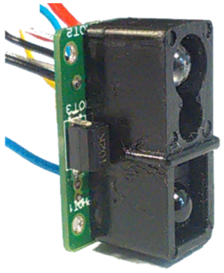
The device is represented in
Figure 1 and its specifications are listed below
Range: up to 6 m
Width: depends on range, equivalent to the width of our electric wheelchair (55 cm) for a range of 4 m.
Cadence: 50 Hz
Power consomption: < 10 mA
Dimensions: 22 mm × 12.5 mm × 12.7 mm
Sunlight immunity verified up to 100 kLux
The sensor works by proximetry. This involves illuminating an obstacle and measuring the backscattered light flux in order to evaluate its approximate distance. To this aim, at a minimal energy cast, our sensor fires a series of increasing power shots of light, until it is able to detect part of the backscattered signal. The required power depends on the distance to the obstacle and on its nature (size, albedo, etc.).
The main components of the sensor are:
An infrared LED (950 nm) modulated at 40 kHz, delivering the series of luminous shots of increasing intensity. These shots are modulated at 40 kHz and increase in a duty cycle until a return signal is detected (the minimal power needed to activate the optoschmitt).
An infrared optoschmitt with an optical bandpass filter at 950 nm followed by a narrow band electrical 40 kHz filter with automatic gain control. It detects the signal backscattered by the first obstacle encountered.
A phototransistor with 950 nm optical bandpass filter to evaluate sun light at 950 nm. It is used to measure ambient luminosity due to sunlight at 950 nm. Indeed, ambient light changes the polarization point of the photodiode in the optoschmitt, and its sensitivity decreases with the intensity of the ambient light. The phototransistor then makes it possible to adapt the power of the light shots by the infrared LED to the ambient brightness, in order to maintain a satisfactory signal-to-noise ratio on the optoschmitt.
Subject to a calibration is possible to evaluate the range in which an obstacle is located in relation to our sensor. The stronger the sun rays, the more powerful the infrared LED’s shots.
To ensure robustness the sensor has to be calibrated for all light conditions, from dark night to full summer sun. To achieve this, a machine was developed to automate the process. It remains outdoors all day and all night long, and carries out series of measurements at 16 different light levels, from 0 to 100,000 lux. Thus, regardless of the dispersion of the characteristics of the LEDs and photoreceptors we get reproductible sensors whatever the ambient luminosity.
This calibration is carried out on wooden panels painted with a specific reference paint, which remains the same over time (70% albedo at 950 nm).
We are not seeking a precise measurement of distance but rather just an order of magnitude. Below is an approximate correlation between range and actual distance:
Very short: < about 1 m
Short: between about 1 and 2 m
Medium: between about 2 and 4 m
Long: between about 4 and 6 m
Very long: > about 6 m
Figure 2 illustrates the different range cone. The mathematical evaluation of the shape of the cones is explained in the publication of José Villanueva and René Farcy [
15].
In the context of our application, and in order to achieve clean avoidance with the wheelchair, which does not hit any obstacles without moving too far away from them, a hysteresis has been introduced into the sensor. This means that the distance used to go from “non-detection to detection” will be shorter than the one used to go from “detection to non-detection”, for all ranges considered. This makes it possible on the one hand to avoid effects of detection instability around the thresholds of each range. On the other hand to give to each detected passage a certain depth, thus making it possible to identify passages wide enough without obstacles to pass through.
Below,
Table 1 show an example of hysteresis values used when calibrating the proximeters on appropriate panels. It should be noted that these panels have their own size and color, and that the hysteresis measured with other types of obstacles will be different, as will be explained below.
As the sensor measures the amount of light backscattered by an obstacle, it is therefore sensitive to the nature of the obstacle (size, color, shape, etc.). This is why we consider detection intervals, not specific values.
To investigate the detection variations with respect to obstacle color, we carried out an experiment [
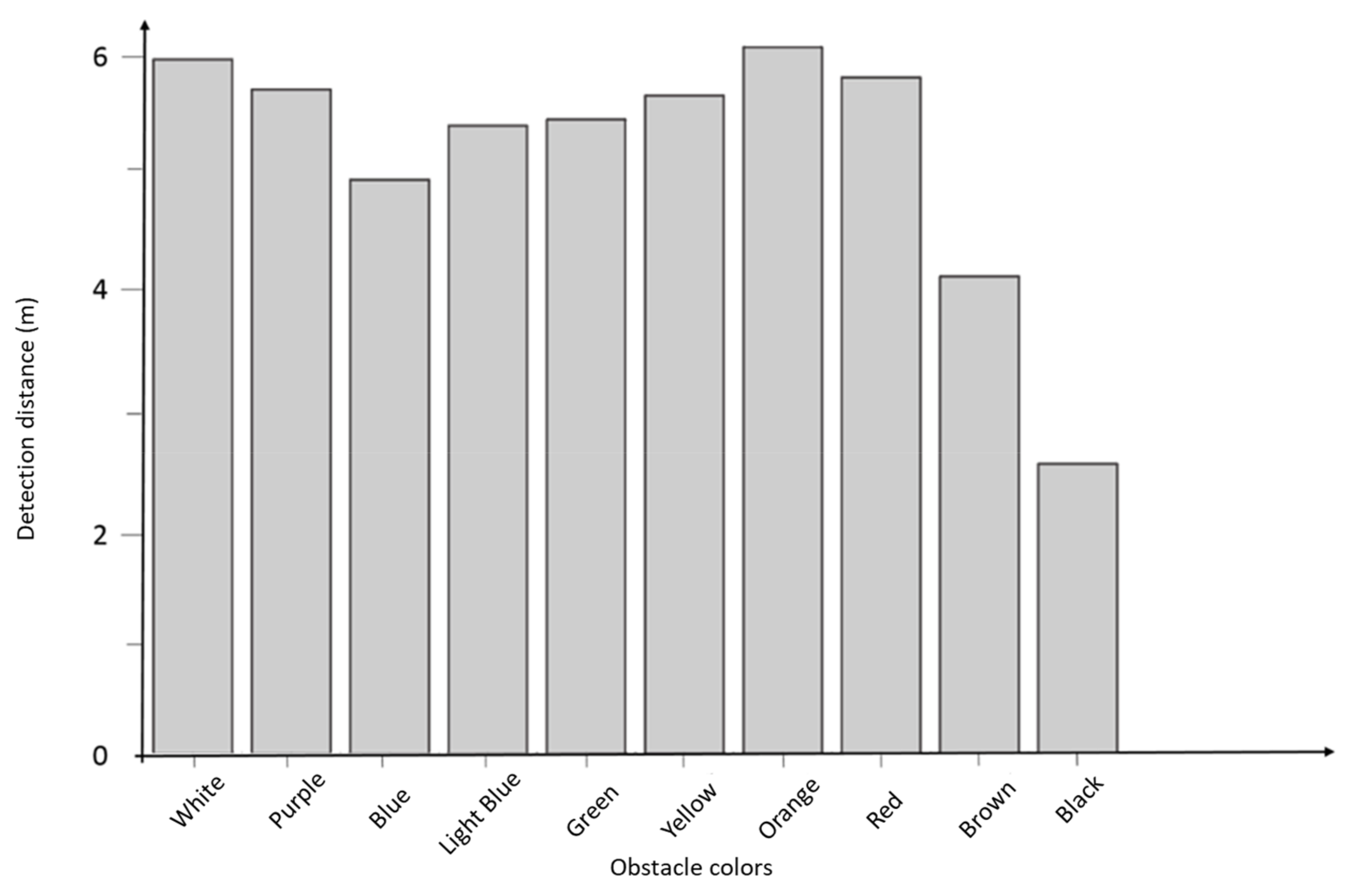
15]. Note that the amount of light reflected by an obstacle depends on its reflectivity at the emission wavelength. In our study, the beam wavelength is in the near infrared, at 950 nm. For this value, the reflectivity is less contrasted than in the visible range. The following results (
Figure 3) are obtained for the same obstacle, i.e., a wooden panel, painted in different colors:
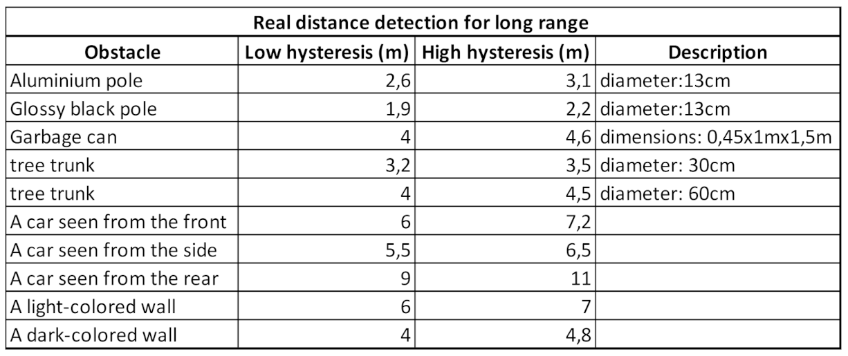
It is well known that the urban environment consists in an ensemble of highly cooperative surfaces (traffic signs, license plates, etc.) and very stealthy ones (thin black traffic poles, etc.). In
Table 2 we report the actual distance of certain specific obstacles from our sensor, when detected within the long range, (roughly in the interval [
4,
5,
6] m).
Over-detection comes mainly from car license plates, specially designed on cataphote surfaces to obtain good contrast on photos of speed camera flashes. This does not prevent car detection but makes it more anticipated. Road signs also give over-detection, but these are generally high up and out of the proximeter’s field of view since its effective action height is that of an electric wheelchair. However, if these are placed low on a sidewalk, for example during roadworks, even if there is enough room to pass on one side, the system is likely to miss this passage, due to over-detection.
Under-detection concerns black and thin obstacles. These are problematic and need to be resolved with additional sensors. This is why we chose to implement ultrasonic sonar.
Because our proximeter returns detection intervals ranges of the order of meters or tens of centimeters for the shortest distances, it is important to mention that a precise knowledge of the distance is not necessary to avoid obstacles. In fact, nobody is visually capable of accurately estimating distances to obstacles, yet anyone is able to walk around safely without contact with its environment. Therefore, this device is not designed to measure distance to obstacles accurately, in order to map the environment, but to evaluate the presence of passages: long, medium, short, very short, corresponding to thresholds of backscattered light respectively weak, medium, strong and very strong.
In conclusion, it is important to emphasize that this sensor is functional and robust under all conditions, at a high-speed measurement (50 Hz), with low energy consumption and space requirements. It is also able to check with a high degree of confidence if an electric wheelchair has room to move.
4.2. Ultrasound Sonar
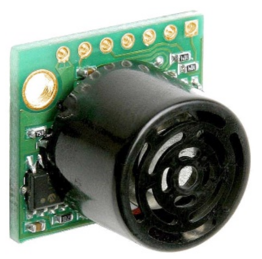
We also use ultrasonic sonar to complement our infrared proximity sensor, particularly for detecting fine and/or dark obstacles. After testing a dozen of different sonars and considering their power consumption, accuracy, detection width, size, rate and integration potential, we finally decided to use the LV-Max Sonar-EZ0 from MaxBotix
®, represented in
Figure 4.
It has the following characteristics:
Range: reliable up to 2 m (according to our tests)
Width: approx. 120 cm (for 2 m propagation)
Cadence: up to 50 Hz (for distances < 2 m)
Accuracy: 1 cm
Power consumption: 2 mA
Overall dimensions: 22 mm x 20 mm x 15.5 mm
Immunity to sunlight (mechanical waves are not sensitive to light)
The sonar is based on the time-of-flight principle, i.e., it measures the time between the emission of an ultrasonic wave and its reception after bouncing off the first obstacle encountered. Due to the speed of sound, the signal reaches an obstacle at a distance equal or less than 2 m and returns to the wheelchair in only 12 ms. Such a short time makes this sensor well adapted to our application.
The nature of the sonic waves allows a good detection of small obstacles. Moreover, they are not affected by the obstacle colors (whether they are dark or completely transparent), in contrast to the proximeter which has certain limitations, as we have seen in
Section 4.1.
However, one of the main shortcomings of our sensor lies precisely in the mechanical nature of its waves. In fact, an ultrasonic wave can easily bounce many times before returning to the sensor yielding a distortion in the measurement, (or in the case with multiple ultrasonic sensors, it can bounce back to another sonar pointing in another direction). Due to multiple bounces, the probability of incorrect measurements or false positives on other sonars used simultaneously is high. It is therefore necessary to limit the use of several sonars at the same time. This is particularly significant given that sensors are designed to be able to detect very weak returned signals, to take account of their attenuation during propagation.
In our case, to protect the entire area around the user’s wheelchair, we need to install enough ultrasonic sonars around the perimeter of the wheelchair. The higher the number of sensors, the better the security and spatial resolution of our system. However, the greater the number of sensors, the greater the risk of false positives (obstacles detected when none exist due to multi-bounce). To avoid this kind of problem, we have set our system in such a way one sensor fires after the other.
Empirically, we were able to define through several tests in confined environments (corridors, cluttered rooms, etc.) that a 30 ms waiting period between two consecutive ultrasound sonar shots was sufficient to drastically reduce the number of false positives. This applies when only obstacles within a 2 m radius are considered (in the case of a wider detection range, this delay would have to be increased).
4.3. Disposition
We will now describe the combination of sensors and the operation of the system.
In
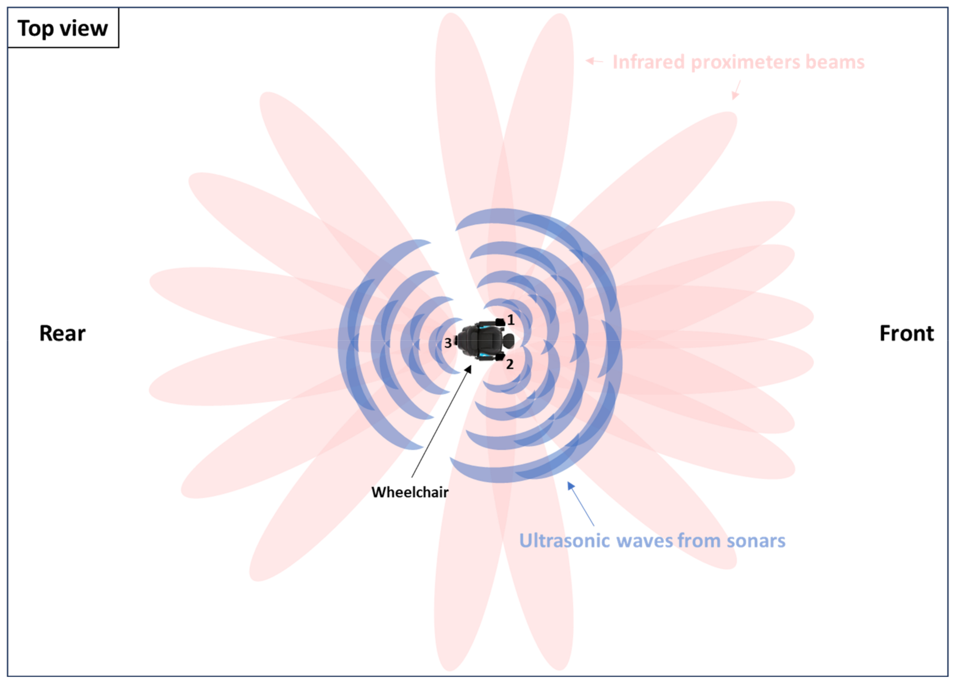
Figure 5, we represent 3 numbered boxes: one on the rear of the wheelchair (3) and two on the armrests (1 & 2). Each box contains a total of 9 sensors: 6 infrared proximeters and 3 ultrasonic sonars. We can notice that all the directions around the wheelchair are covered by several sensors. Particular attention should be paid to the front, the diagonals and the rear of the wheelchair. The rear sides and flanks are less protected, simply because the wheelchair never moves in these directions.
In
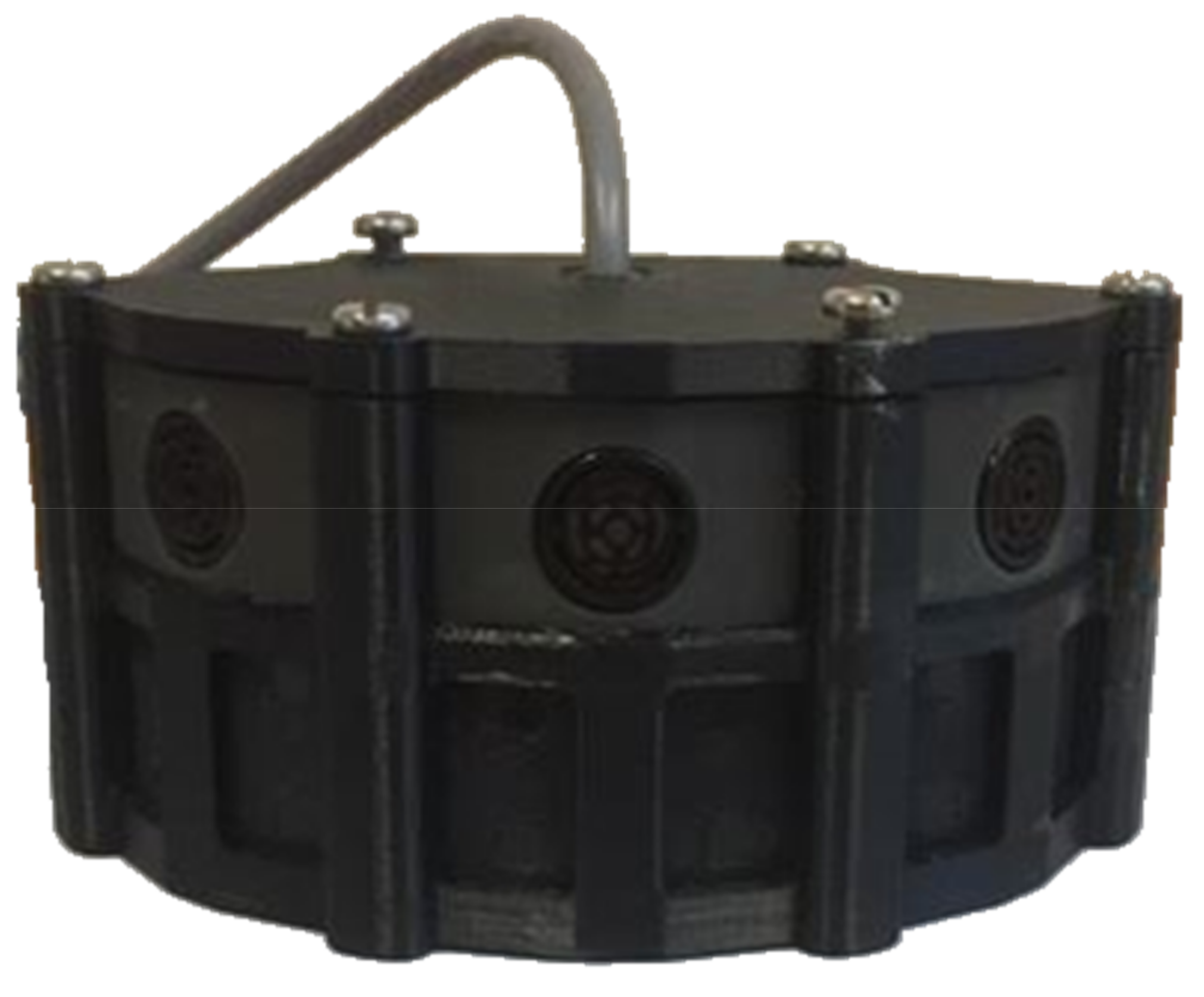
Figure 6 below, we can see how our sensor box is constructed, with ultrasound sonars at the top and infrared proximeters at the bottom.
This construction allows good optimization of the size of the system, with 9 sensors and the electronic processing card contained in a box of approximately 7 cm * 9 cm * 6 cm.
4.4. Algorithm
In line with the development orientations presented in introduction, the algorithm associated with our sensor array limits speed according to the distance and position of obstacles surrounding the wheelchair.
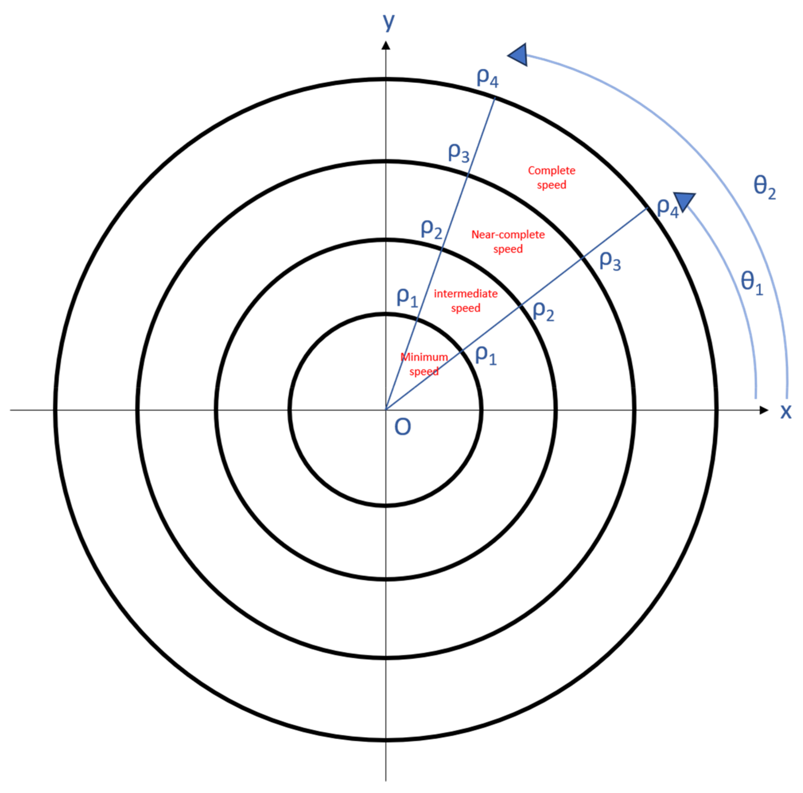
According to the distance between the wheelchair and the obstacle the speed of the latter is limited. The closer the obstacle, the lower the speed. The user can go at any speed between 0 km/h and the speed limit set. There are 4 discrete values of speed limits, which can be labeled: “minimum speed limit”, “intermediate speed limit”, “near-complete speed limit” and “complete speed limit” corresponding to a non-limited speed. There are three main reasons to operate in stages rather than on a continuous basis for the limits: On the one hand, our infrared proximity sensor operates discretely at different range levels, as explained in
Section 4.1. Secondly, it’s important for users to be able to distinguish between the different levels of slowdown, as this is information in its own right. For visually impaired people, it is important to be able to identify which situation leads to which level of deceleration, in order to better assess the dangerousness of a given direction. This would be more complicated if the speed limit were too progressive. Finally, to enable smoother navigation, so that the wheelchair is not constantly accelerating or decelerating, but allows directions to be taken at a well-defined speed.
It is worth emphasizing that there is no zero-speed limit in the context of our collision avoidance algorithm. As explained previously, the user will always be able to move regardless of the congestion of the place where they are, at a minimum speed without causing problems in the event of collisions. This is justified by the fact that users must constantly be able to make contact with their environment.
The position of the obstacle is determined by the sensor detecting it. For example, if one or more diagonal sensors measure a reduced distance, this means that an obstacle is present in the diagonal of the wheelchair. Therefore, the speed limit will be only applied if the joystick is directed diagonally, respectively to the distance from the obstacle.
To achieve this operation, it is first necessary to modify the interpretation and management of the data provided by the user’s joystick. Indeed, the standard operation of a joystick is carried out in Cartesian coordinates. The
x and
y tension values allow to find the direction and speed of the wheelchair. With the aim of applying an efficient algorithm, we convert the Cartesian coordinates in Polar coordinates. This left us with two distinct variables: the polar angle θ and the radius ρ, which represent the direction and the speed, respectively. Considering sensors information, it is possible to set a limit radius ρ, in a range of θ values. As a result, we have a speed limit in a given direction. In
Figure 7 we show the different speed limit levels, in a given direction (namely the diagonal to use the previous example).
5. Experimental Tests
The biggest challenge in the aim of securing the movement of electric wheelchairs is the ability of the system to correctly detect the obstacles surrounding it regardless of the environmental conditions or nature of the obstacle. In order to check the quality of our system and to verify the right choice in the association of our sensors, we carried out a series of measurements to assess their robustness depending on the situation. It should be noted that these measurements were carried out outdoors at midday in order to verify their good immunity to sunlight. Furthermore, a robustness up to 100,000 lux has been demonstrated in the publication [
16].
Three experiments were carried out. Each with the aim of testing the sensor system in particular situations: 5.1 Frontal movement towards obstacles of different types; 5.2 Rotation movement facing a wall; 5.3 Comparison of spatial resolutions.
5.1. Frontal Movement towards Obstacles of Different Types
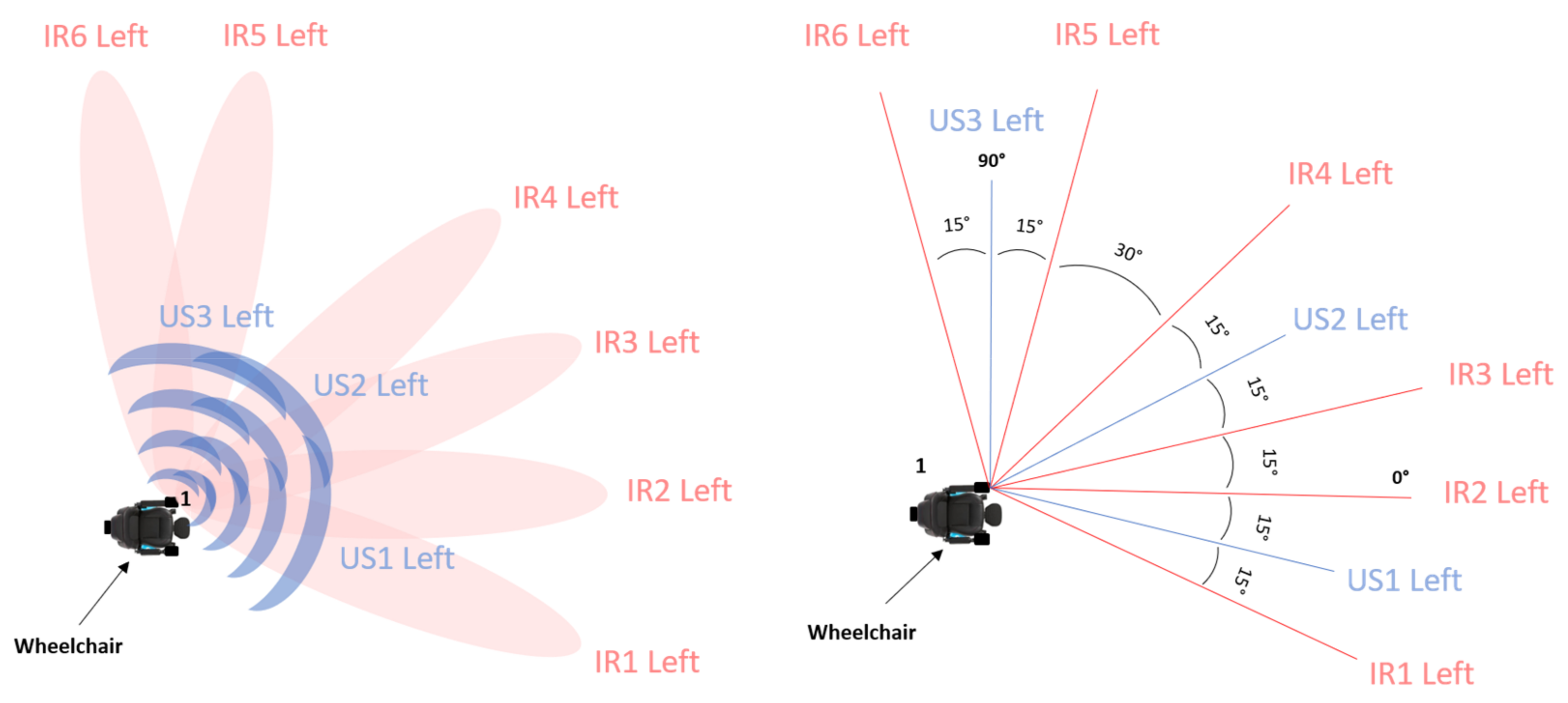
In this experiment we verify the effectiveness of our sensors individually, ultrasound and infrared, depending on the nature of the obstacle in front of the chair. For this purpose, seated in the wheelchair, with the anti-collision system activated, we head towards an obstacle, measuring the speed of the wheelchair continuously as well as the distance which separates it from the obstacle, while recording the values returned by our sensors. This was done in 4 different situations: without obstacle, with a thin and dark obstacle, with a medium-sized and dark obstacle and with a medium-sized and light-colored obstacle, in order to evaluate the differences in behavior of our sensors depending on the obstacle encountered. For the sake of identification our infrared and ultrasound sensors are numbered as follows: starting from the inside of the wheelchair and working outwards. The numbering is independent between ultrasonic and infrared sensors. This numbering as well as the angular position of the different sensors is illustrated in
Figure 8 below.
In order to have readable results, it was decided to only represent the values of our front sensors, namely IR1, IR2 and US1, placed on the left and right armrests of the wheelchair, as the other sensors are not involved in the detection of frontal obstacles. Below,
Figure 9 represents the sensors concerned as well as their angular position.
The wheelchair starts at t = 0 s and stops when it collides with the obstacle which is at a distance of 5 m from the starting point (or when the wheelchair exceeds 5 m when there is no obstacle). The relationship between time and distance will be studied. The test shows the delay between the detection of an obstacle and the slowing down of the chair.
5.1.1. Case without Obstacle
This first step essentially allows to establish the reference frame for our experience. This requires observing the evolution of the speed of the wheelchair, over a given distance.
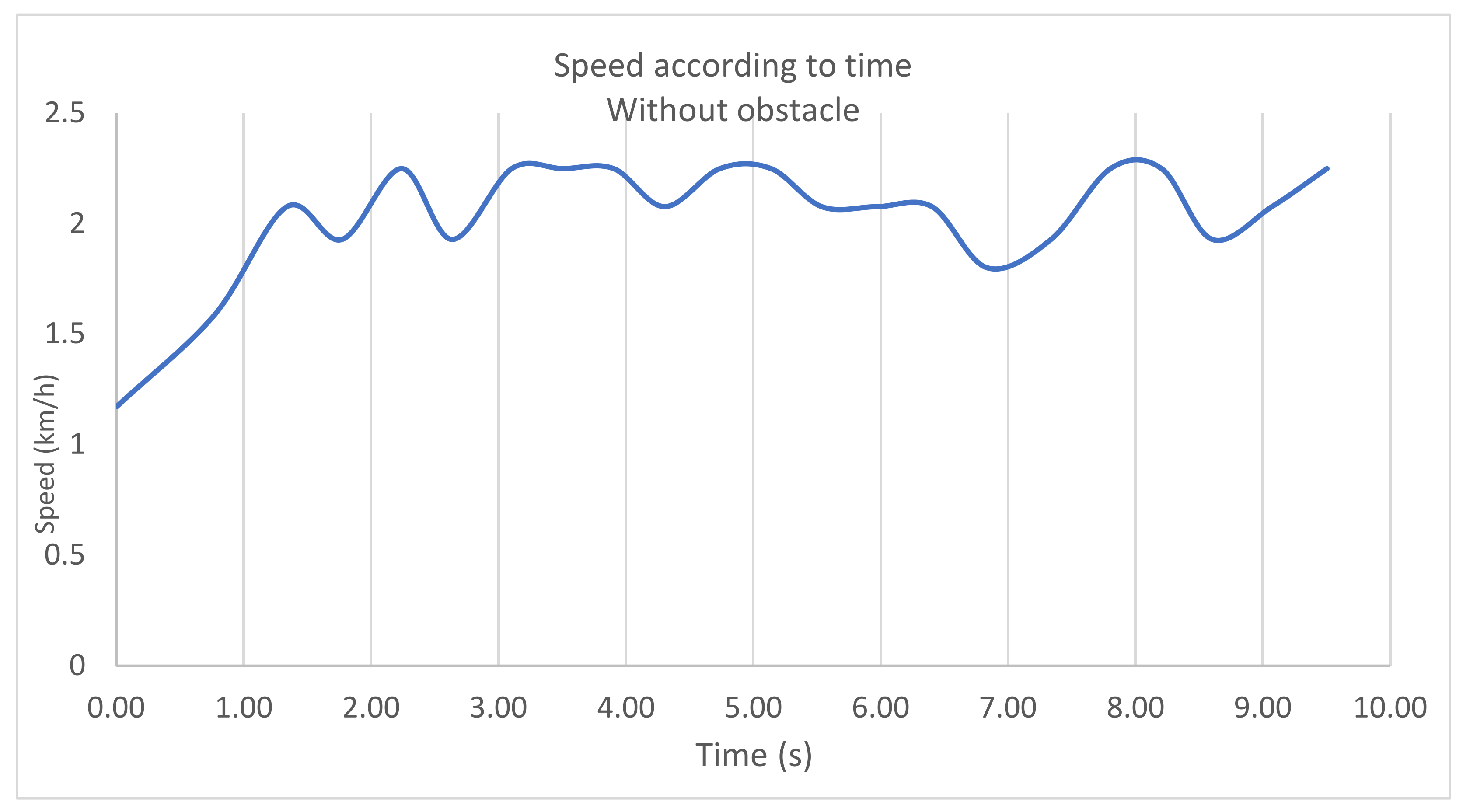
When we observe the speed evolution curve, we notice, unsurprisingly, an initial phase of acceleration up to a constant speed phase which oscillates around 2.2 km/h. The oscillations in
Figure 10 result from the uncertainties on the speed measurement (by post-video processing) as well as on the real slight variations in speed which are due to the imprecision of our hand on the joystick that is constantly realigning the wheelchair with the desired rectilinear trajectory. It should be noted that these slight speed oscillations will be found in all the measurements of the experiments carried out.
Let us note that the maximum speed reached −2.2 km/h- is adjustable at will within the limit of 10 km/h. Likewise, the speed limits are completely adjustable. The maximum speed depends on various factors, including the anti-fall detection discussed in the article (Favey, Sensors [
5]).
Here it is not relevant to present sensor data due to the absence of obstacles.
5.1.2. Case of a Thin and Dark Obstacle
To carry out this experiment we used a thin black pole, with a diameter of 5 cm and a height of 1 m. Like each of the obstacles, this one was placed at a distance of 5 m from the starting point.
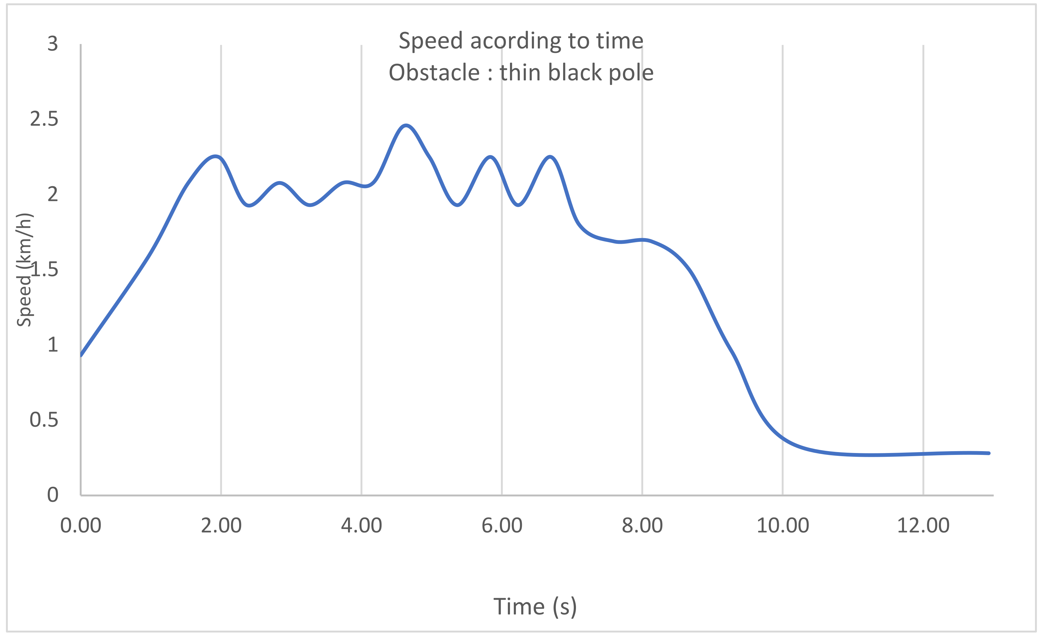
When we look at the speed evolution in
Figure 11, we notice 3 phases. An acceleration phase, a constant speed phase and a deceleration phase. The first and second phases are logically similar to the first situation in absence of obstacle. We are mainly interested in the deceleration phase.
When we focus on the recorded values, the first notable deceleration (i.e., which comes out from oscillations around 2.2 km/h) occurs at 7.10 s after the start, at a distance of 3.25 m (i.e., 1.75 m of the thin black post). Distances are obtained by video analysis of the wheelchair’s progress on a marker graduated every 25 cm.
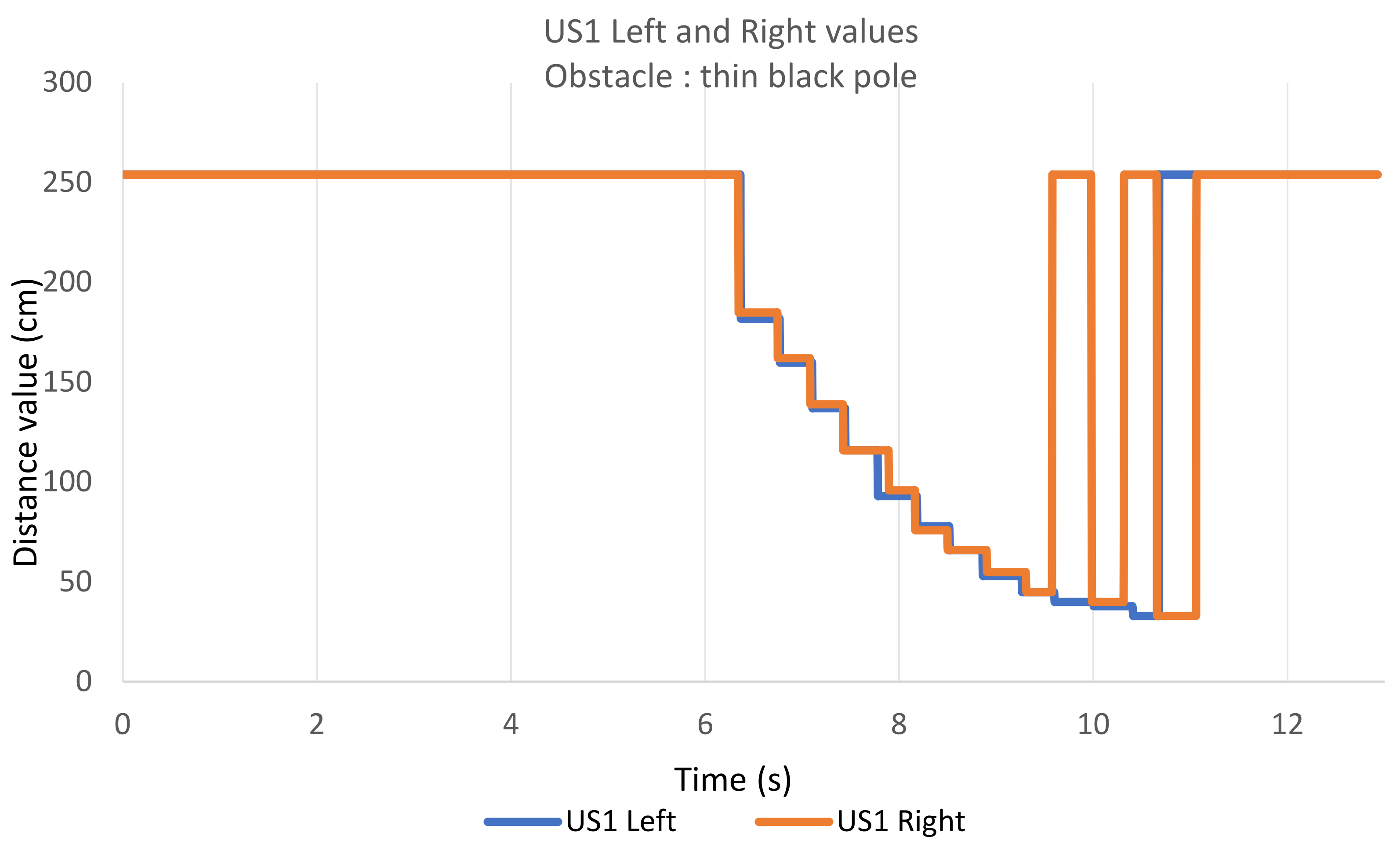
Figure 12 and
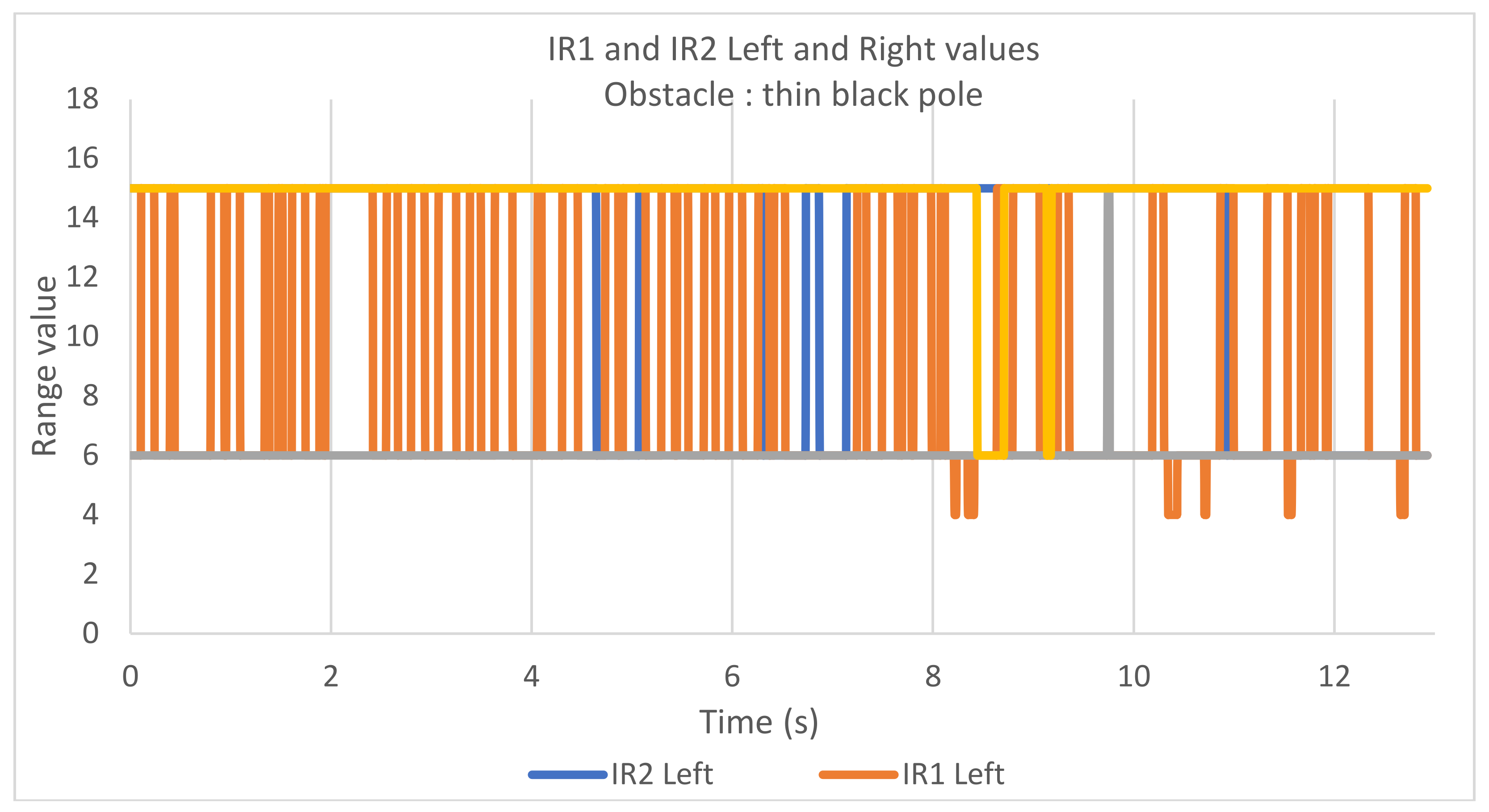
Figure 13 below shows the evolution of the values of the sensors concerned over time, as the wheelchair moves forward.
The infrared and ultrasound sensor data indicate that only ultrasound can detect the thin black pole. In fact, infrared proximeters oscillate between “long” and “very long” ranges (with the exception of a few rare detections at “medium” range with the value 4). In this case, the infrared proximeters are not functional, which could be expected since a thin and dark obstacle reflect very few the light flux.
We list some points of interest below:
The obstacle is detected by ultrasounds 6.4 s after departure, when the wheelchair is at a distance of 1.75 m from the obstacle. We therefore have a 0.7 s delay between the detection of the obstacle and the first feeling of slowing down (noted at 7.1 s), as well as an advance of 0.5 m. This is explained by the inertia of the wheelchair.
The staircase shape of the data emanating from the ultrasonic sensors is explained by the fact that their values are recorded with a frequency higher than that of their measurement rate.
From 9.5 s we can observe that the ultrasonic sensors “drop out” at times. This is because the wheelchair makes contact with the obstacle (at the extremely low speed of 0.3 km/h), which leads the black pole to end up between the ultrasonic sensors, thus causing an alternation between detection and non-detection. It does not matter since the system allowed the wheelchair to slow down before colliding with the obstacle.
5.1.3. Case of a Medium Sized and Dark Obstacle
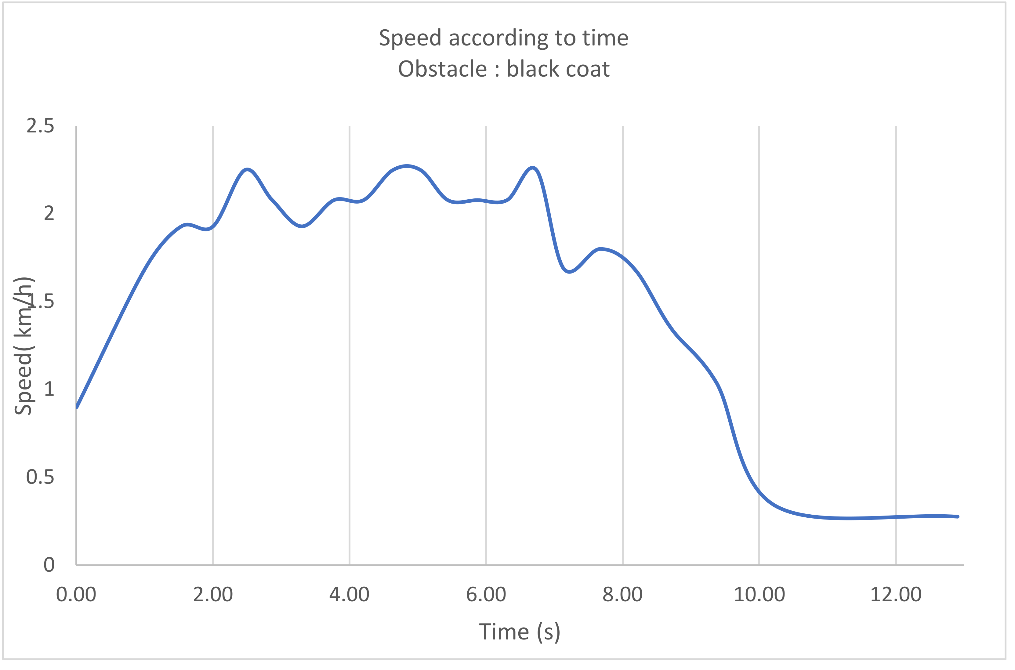
In this new configuration of the experience, we use completely black rain jacket, which we installed on a valet which is then equivalent to an obstacle of 40 cm wide and 1 m high. The ensemble was placed 5 m from the starting point.
Figure 14.
Speed evolution with a black coat as an obstacle.
Figure 14.
Speed evolution with a black coat as an obstacle.
Similarly to the previous case, we observe 3 phases: acceleration, constant speed, deceleration. As before, the deceleration is of particular interest to us. This latter starts significantly at 7.14 s at 3.25 m from the start (i.e., 1.75 m from the obstacle), in the same way as the previous obstacle.
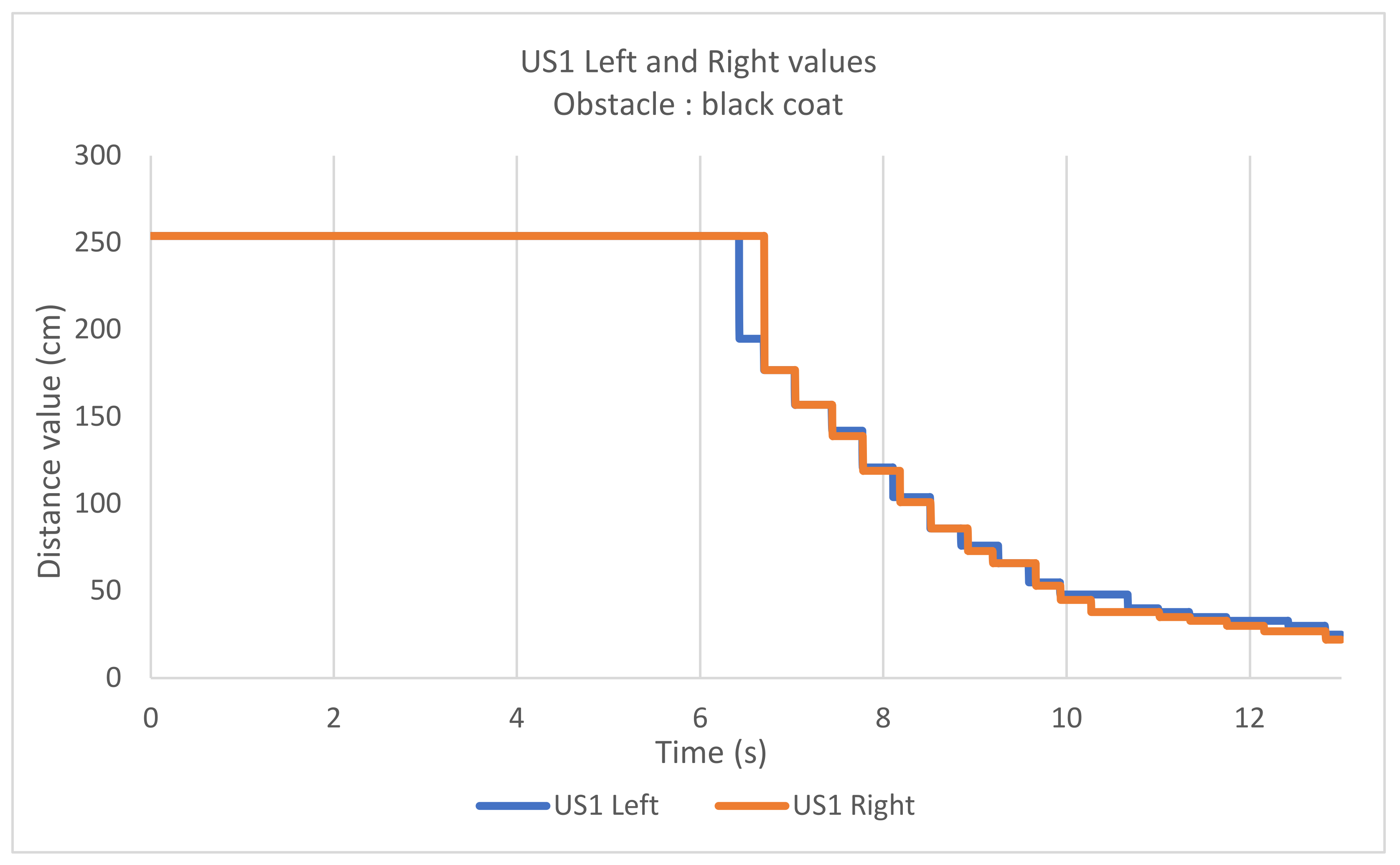
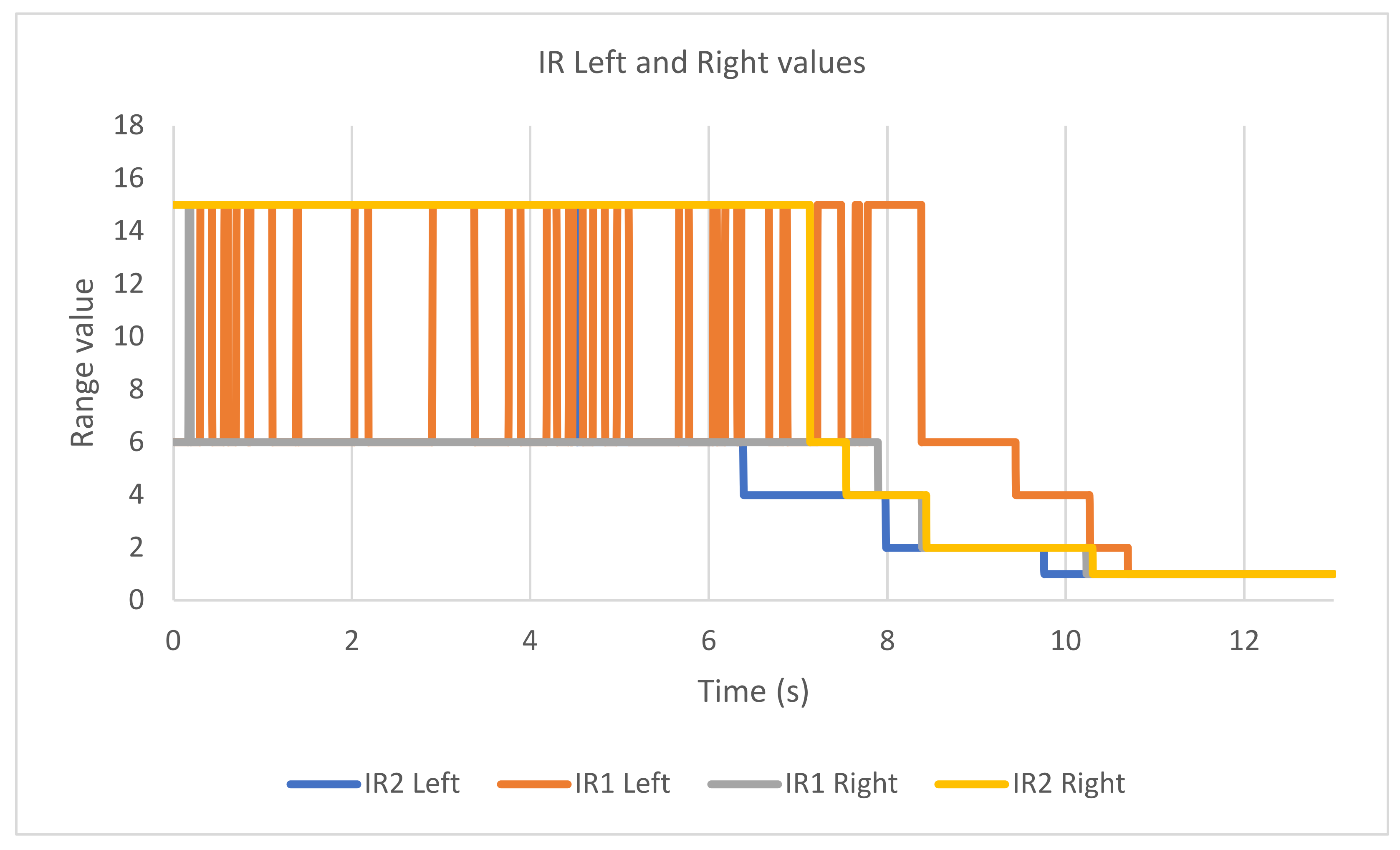
In this case, when we examine the sensor values in
Figure 15 and
Figure 16, we observe detection from both ultrasonic sonars and both infrared proximeters. The obstacle is detected simultaneously by the 2 ultrasonic sonars and the left IR2 proximeter at 6.4 s, 3.25 m from the start (or 1.75 m from the obstacle, like the thin black pole case).
The timing differences in the detection of infrared proximeters can be explained by their differences in orientation with respect to the obstacle. In fact, in real conditions the wheelchair is never perfectly aligned with the obstacle.
5.1.4. Case of a Medium Sized and White Colored Obstacle
This experiment was performed by using a white coat installed on a valet, constituting a clear obstacle having dimensions: 1 m high and 40 cm wide.
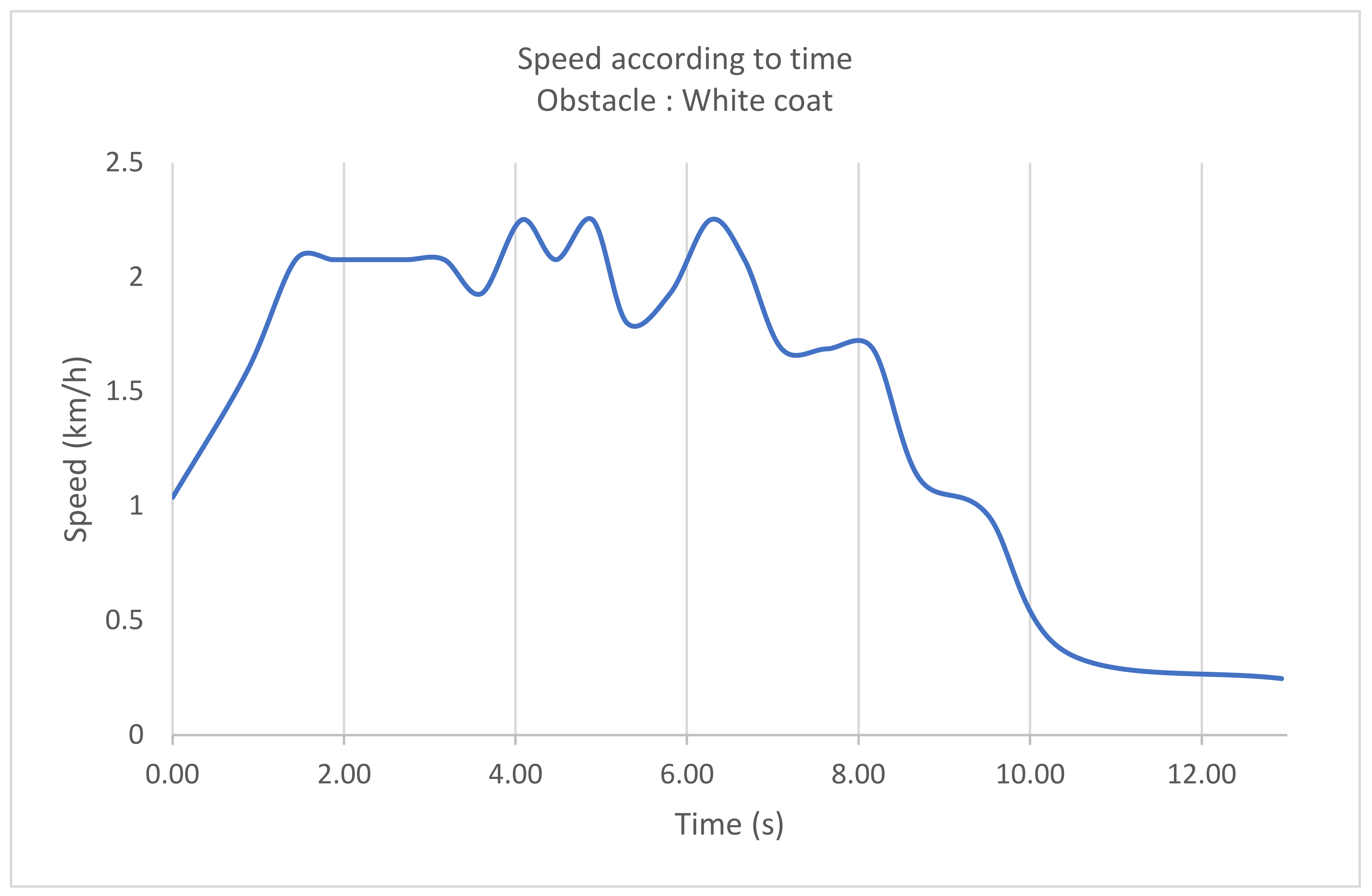
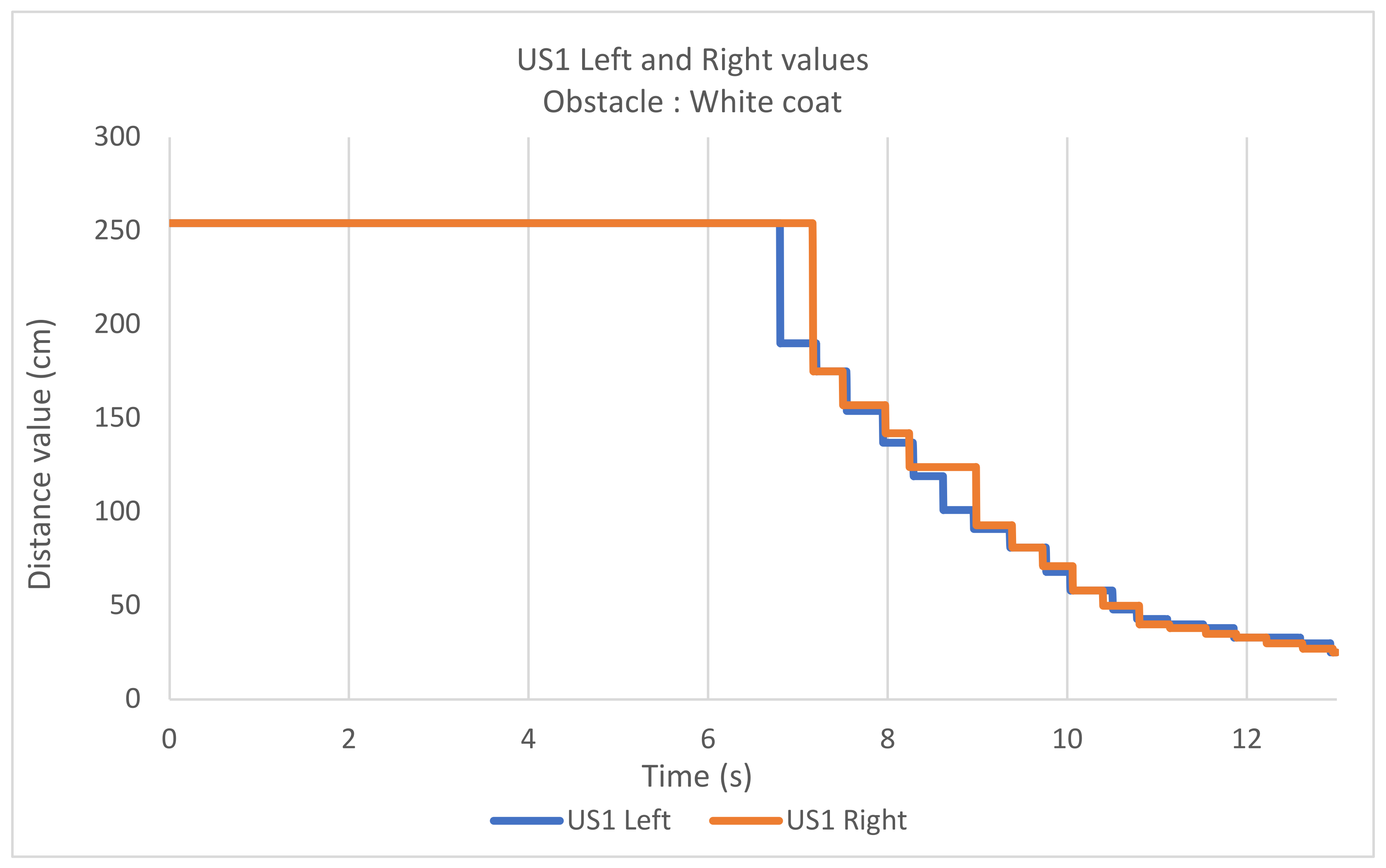
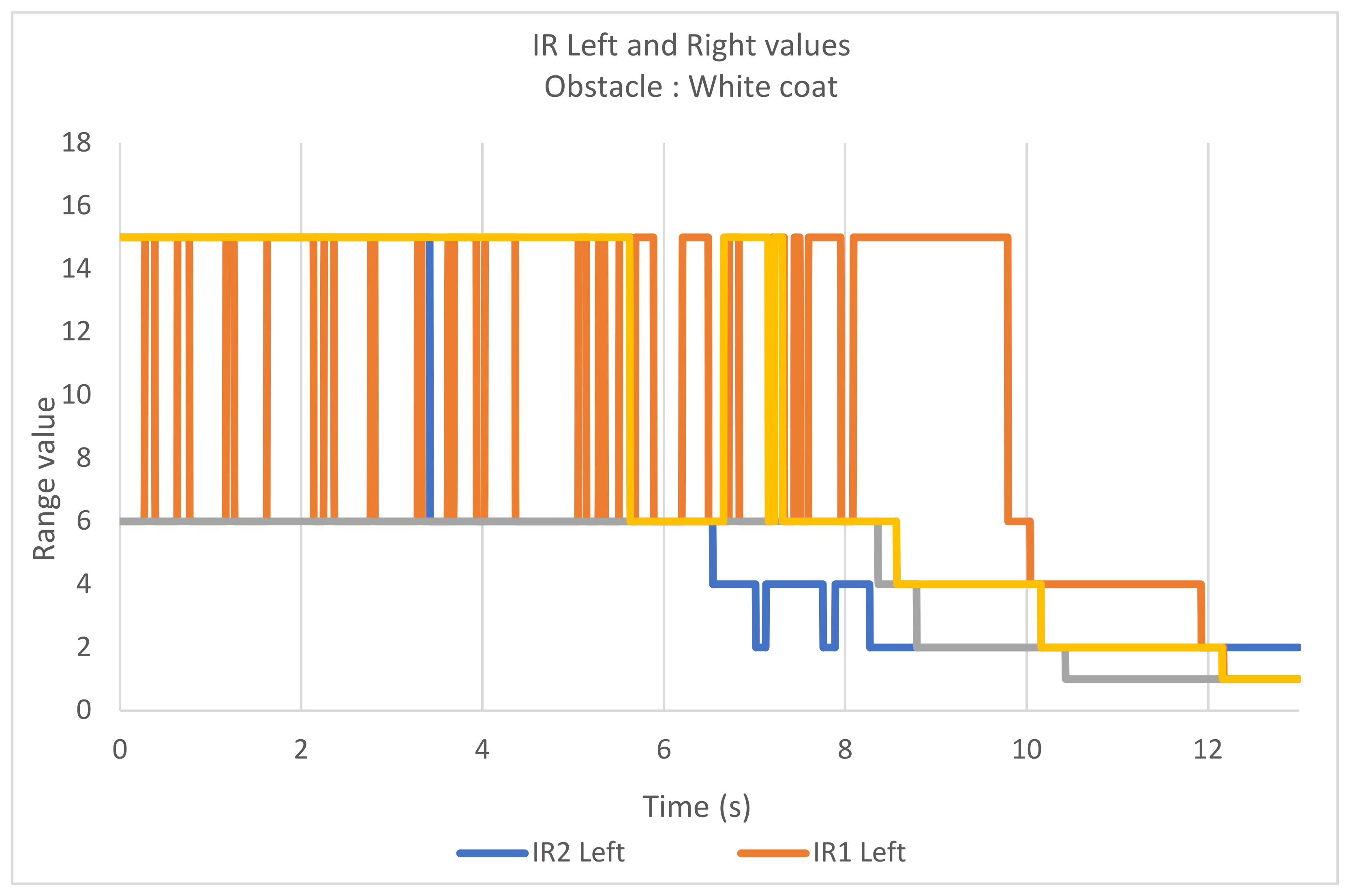
Figure 17,
Figure 18 and
Figure 19 show, respectively, the evolution of wheelchair speed as a function of time, the values returned by ultrasonic sonars and the ranges returned by infrared proximeters.
Again, we find the same 3 phases of acceleration, constant speed and deceleration. As in the two previous cases, the deceleration becomes noticeable at 7.1 s, at a distance of 3.25 m from the start or 1.75 m from the obstacle.
The recorded sensor values are comparable to those in the previous situation (medium size and dark obstacle). In particular, we note an approximately synchronous detection of the obstacle by the ultrasonic sensors and the IR2 left proximeter, occurring at 1.75 m from the obstacle (at 6.4 s), yielding a slightly delayed detection of the other infrared proximeters.
5.1.5. Analysis
In the 3 cases involving obstacles, these are detected in the same way by our system, i.e., at a distance of 1.75 m from the obstacle, causing a noticeable slowdown of 0.5 m later, whatever the nature of the obstacle. This occurs because the caused slowdowns seem to involve the ultrasonic sonars, which correctly detect the obstacle.
In fact, considering infrared proximeters we observe on average a delay in detection compared to ultrasonic sonars on medium sized object (regardless of their colors) and a non-detection on small dark objects. It could then be questioned the necessity of using infrared sensors as they are not involved in detection. However, as explained previously, there are limitations in the use inherent to ultrasonic sensors with regard to their maximum detection range as well as their detection rate, due to the excessive presence of false positives.
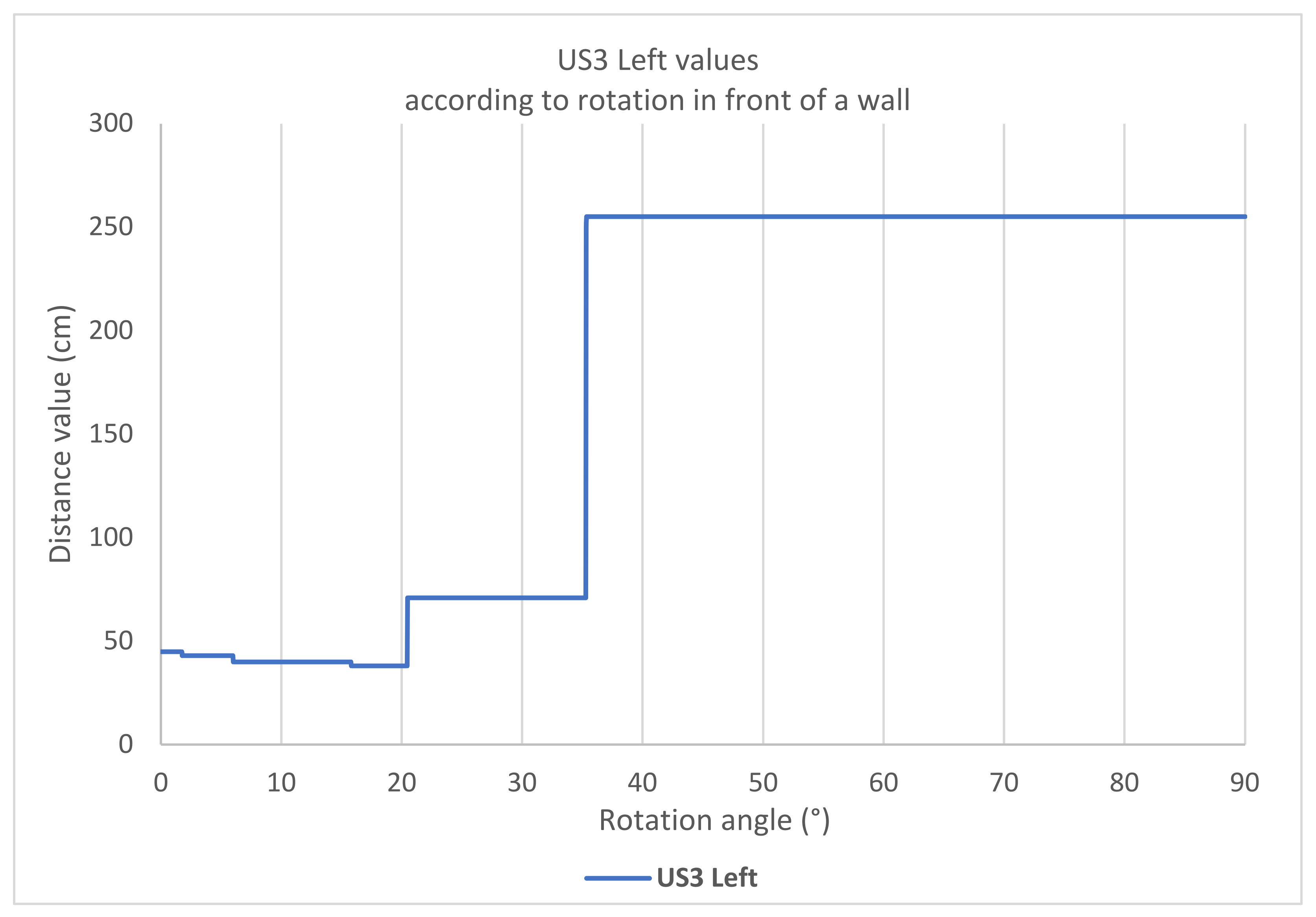
As will be seen in the next experiment, ultrasonic sensors have strong limitations regarding the detection of smooth surfaces with a certain angle of incidence. This is a crucial issue in securing the movement of electric wheelchairs, particularly for the proper detection of walls when the wheelchair drifts gently towards it.
5.2. Rotation Movement Facing a Wall
The aim of this experiment is to evaluate the detection qualities of our different sensors, when seeking to detect a smooth bias surface. This specific research was inspired by daily testing of the different versions of our wheelchair travel safety system. It is clear that this is not as simple task as it might seem. As in the previous experiment, to avoid a plethora of information and to be able to obtain a clear interpretation of the situation, we reduce the number of sensors considered. Therefore, we concentrate on lateral sensors on the left side of the wheelchair, which will satisfactory to carry out our study.
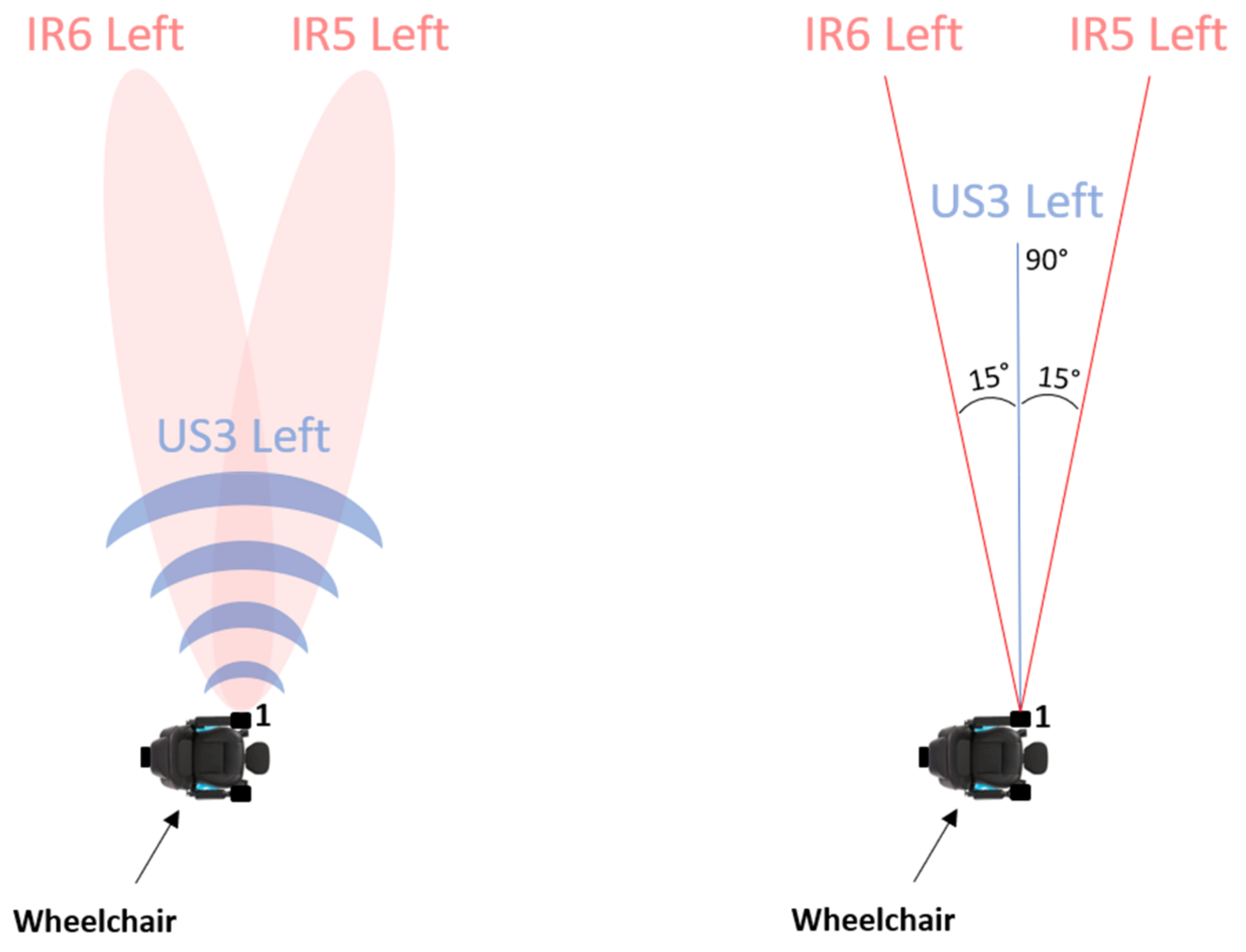
Figure 20 shows the wheelchair with the sensors of interest and their angular arrangement.
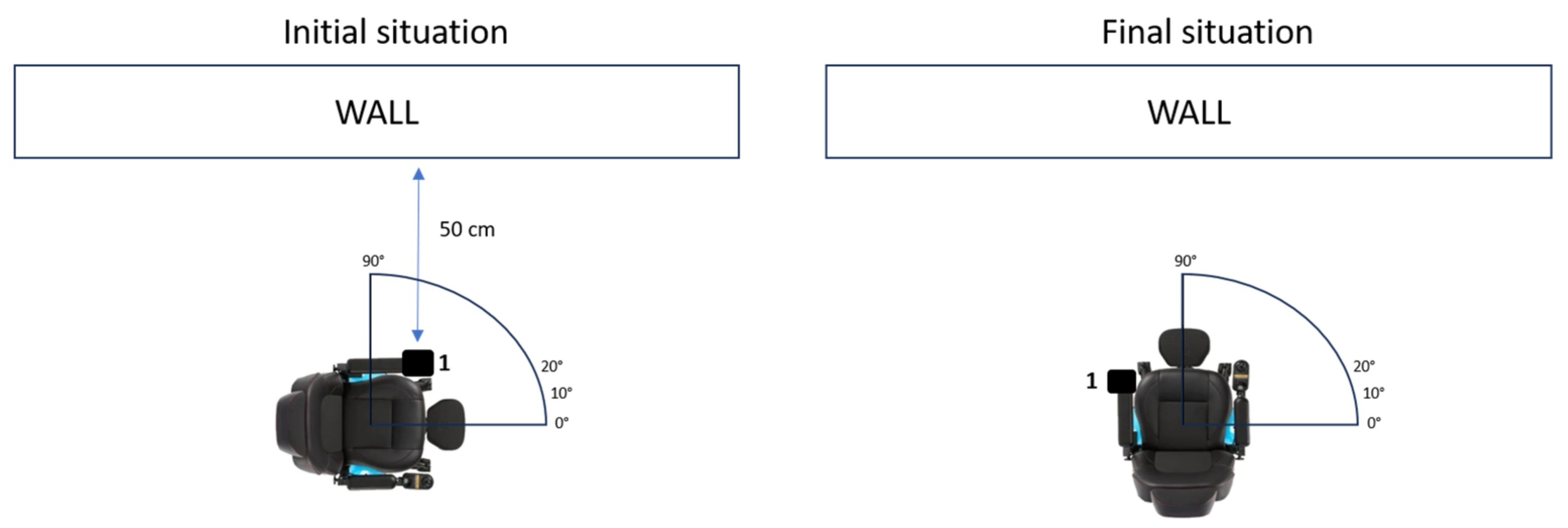
The experiment is described as follows: the wheelchair equipped with our system was placed in profile in relation to a white wall, located 50 cm away. We force the wheelchair to accomplish a quarter turn on itself. As a consequence, it covered an angle of 90 degrees, with the left side parallel to the wall at the start and perpendicular to the wall at the finish. Throughout the rotation we recorded the values of our left US3 and IR5 and IR6 left sensors, every 10°. It should be noted that by design, the left US3 sensor is apparently perpendicular to the armrest of the wheelchair and that IR6 and IR5 are respectively oriented plus and minus 15° from US3. As a result, at the start of the experiment, US3 Left is perfectly perpendicular to the wall.
An illustration of the experiment is shown in
Figure 21.
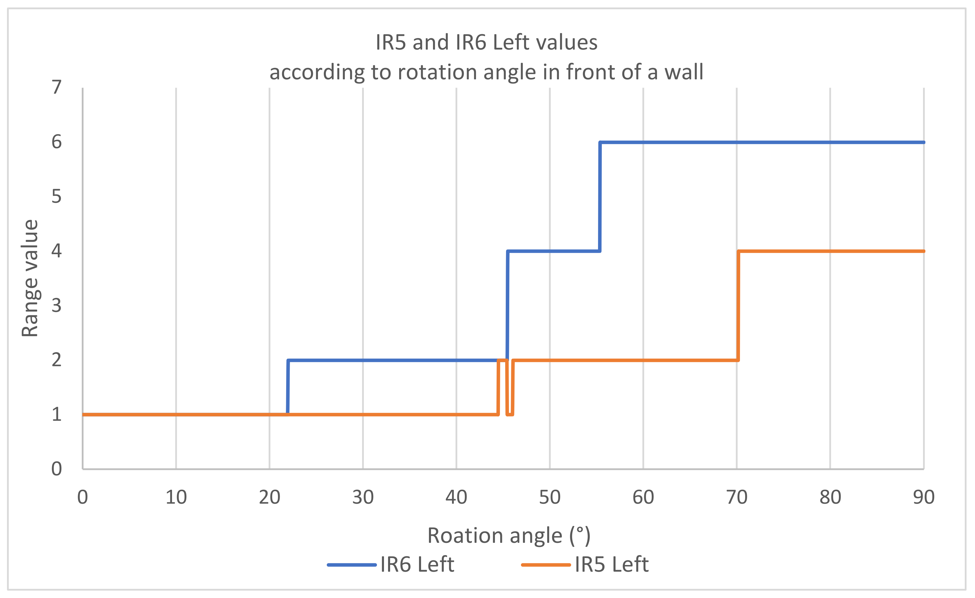
We first notice that when we compare the values originating from our different sensors with each other, is that from 35° of rotation, the ultrasonic sonar US3 no longer detects an obstacle (and therefore returns the maximum value of 255) while the two infrared proximeters IR5 and IR6 never lose their signal and see their range measurement gradually increase as the rotation progresses. It is also interesting to observe that when the angle varies between IR6 and IR5, we have an increase in the measured range of the wall which evolves in an offset manner. Moreover, this offset does not vary when the rotation progresses. This experiment shows that infrared sensors are important for properly managing smooth inclined surfaces which are very common in indoor and outdoor environments.
5.3. Comparison of Spatial Resolutions
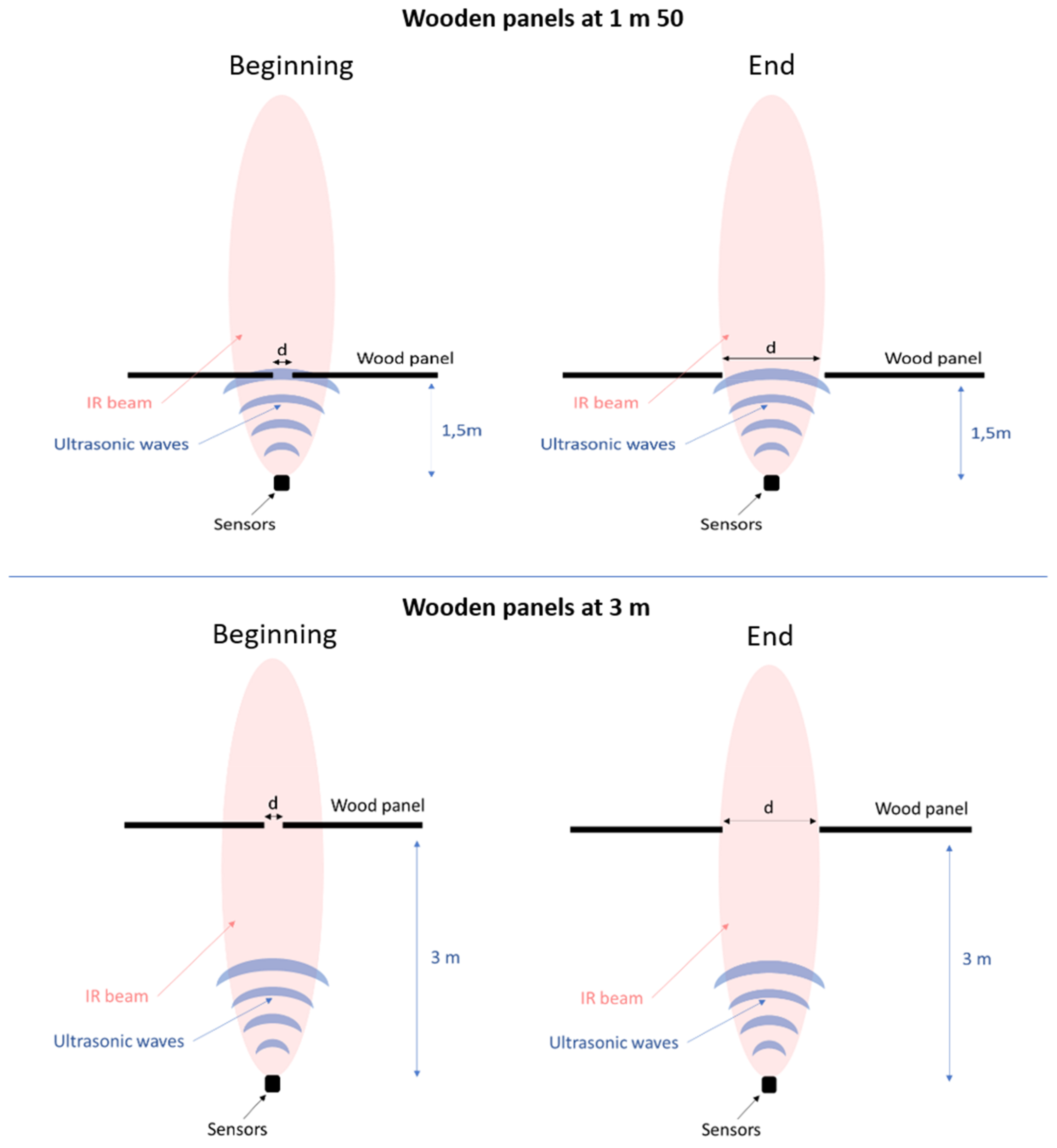
The third experiment aims to compare the different spatial resolutions of our sensors and evaluate the smallest passage without obstacles that the sensors are able to identify. And this, depending on the distance which separates sensors from these passages. We then isolate an ultrasonic sonar and an infrared proximeter, which we superimpose so that they look in the same direction. In front of them we place side by side 2 wooden panels which can form an increasingly larger passage as we increase the distance between the 2 panels. At the beginning of the experiment the two panels are in contact, then spaced 5 cm by 5 cm until we find the time when our sensors are able to “see” the passage in front of them. This experiment was carried out in 2 stages: with the panels located at 1 m 50 from the sensors and then at 3 m.
Below,
Figure 24 is an illustration of the experience.
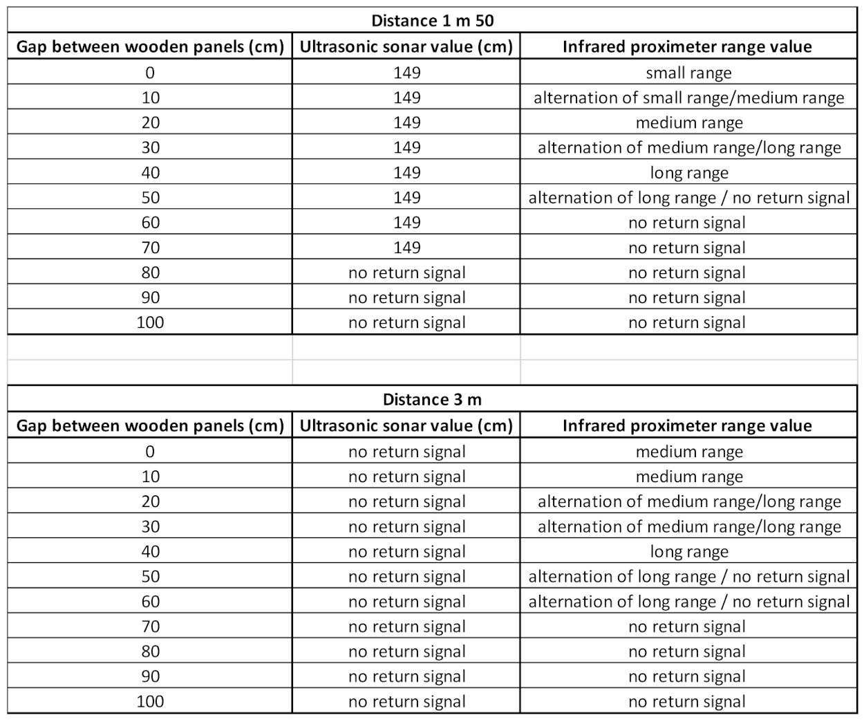
In the first case, i.e., when the panels are 1 m 50 from the sensors, we notice the following two phenomena:
In the ultrasound case, we observe a clear identification of the passage, for a gap of 80 cm between the two panels. After this gap, the sound waves pass through the passage and no longer return to the sensor.
Concerning the infrared proximeter, which works by measuring the quantity of reflected light flux, we logically observe a progressive increase in the detected range, as the gap between the panels increases, followed by a non-detection for a gap greater than 60 cm.
We can then say that at a distance of 1.5 m, the infrared proximeter shows a better angular resolution than the ultrasonic sonar.
In the second case, i.e., when the panels are located 3 m from the sensors, we note that:
The ultrasonic sonar never sends us stable values. As explained in part 3, the ultrasonic sonars are poorly suited for measurements greater than 2 m, due to the conical nature of their emission, dispersing the energy as the wave propagates.
The infrared proximeter which has a behavior similar to the previous case, namely a detected range which increases as the distance between the panels increases, with detection of the passage for a distance of 70 cm.
Considering that electric wheelchairs are between 60 cm and 70 cm wide, it would appear that ultrasonic sonar is better suited to detecting passages at short distances, while infrared proximity meters are better suited to detecting passages at medium and long distances. This guarantees correct detection of passages greater than or equal to 70 cm at any distance within a 6 m radius around the wheelchair.
6. Discussion
Through our bibliographic study as well as the various tests carried out by our team over the years, it was shown that the detection system which seems best suited to for securing the movement of electric wheelchairs was a combination of ultrasonic sonars from the commerce coupled with infrared proximeters developed in-house by our research team. We are committed to giving a wheelchair with an anti-collision function, allowing a satisfactory detection of obstacles and free passages in the surrounding area while taking into account the constraints of size, energy consumption, precision, spatial resolution, robustness and costs.
The whole system was subsequently evaluated in different situations through 3 experiments, which allowed us to verify that the anti-collision function was reliable regardless of the nature of the obstacle, its size, its color, its distance and its position compared to the wheelchair.
The ultrasonic sonars are able to detect fine or dark obstacles with good distance accuracy. Unfortunately, the detection of smooth and inclined surfaces or distant obstacles and passages is not satisfactory. These limitations are compensated by the presence of our infrared proximeters, despite the fact that they cannot be recommended for detecting thin or dark obstacles, they prove to be competitive in detection of smooth surfaces at an angle as well as free passages near and far with sufficient spatial resolution.
The combination of the two technologies allows a smooth and safe movement in any environment, for all electric wheelchair users.
However, several important issues must be addressed. Among them:
Our anti-collision system ensures a satisfactory detection of obstacles located halfway up the wheelchair. It does not allow the detection of small obstacles protruding from the ground or those located high up and potentially at the level of the user’s head. If obstacles at ground level remain detectable, thanks to our anti-fall detection system presented in another article [
5], those located at height should be taken into account in a new sensor system.
The anti-collision system used here has been mechanically tailor-made for our wheelchair model. Although its hooks and their positions have been designed to be as modular as possible and compatible with the majority of wheelchairs in the market. It is clear that slight adaptations are systematically necessary when moving from one wheelchair model to another. Moreover, depending on the user’s disability, their position in the wheelchair or other specific constraints, it is not always easy to install our system or that all the sensors have an optimal detection position (possible obstructions, etc.)
The compatibility of our system with the electronics of the electric wheelchairs in the market (while irrelevant in article), is very important for the purpose of a real and concrete use of our system. In fact, for the moment we use the “special input device” entry which is a standard made available by all manufacturers. However, on the one hand, this input does not provide us with enough power to run all of our systems (anti-collision + anti-fall), so it is necessary to connect it directly to the batteries of the wheelchair, which is not compatible with certification of conformity. On the other hand, we need to add our own external joystick, since we cannot use the information coming from the standard base joystick, via the special input device entry. It will therefore be important subsequently to come to an agreement with the electric wheelchair manufacturers in order to find a solution to these problems.
Author Contributions
Conceptualization, Favey.C and Farcy.R.; Software, Favey.C, Berthe.I, Bogaert.L and Jordan.L.; Investigation, Favey.C, Berthe.I, Bogaert.L and Jordan.L.; writing—original draft preparation, Favey.C.; writing—review and editing, Favey.C and Farcy.R; supervision, Farcy.R.; project administration, Favey.C.; funding acquisition, Favey.C and Farcy.R. All authors have read and agreed to the published version of the manuscript.
Funding
This research was funded by Université Paris-Saclay; UNADEV; Nouvelle Association Santiago Accessible.
Institutional Review Board Statement
Not applicable.
Informed Consent Statement
Not applicable.
Data Availability Statement
Data is contained within the article. Dataset available on request from the authors.
Acknowledgments
Sincere thanks to Djamel Benredjem for his invaluable advice and feedback on this article.
Conflicts of Interest
The authors declare no conflict of interest.
References
- Simpson, R. C., LoPresti, E. F., & Cooper, R. A. (2008). How many people would benefit from a smart wheelchair?. Journal of rehabilitation research and development, 45(1), 53.
- Keeler, E., Guralnik, J. M., Tian, H., Wallace, R. B., & Reuben, D. B. (2010). The impact of functional status on life expectancy in older persons. Journals of gerontology series a: Biomedical sciences and medical sciences, 65(7), 727–733.
- Bray N, Kolehmainen N, McAnuff J, Tanner L, Tuersley L, Beyer F, Grayston A, Wilson D, Edwards RT, Noyes J, Craig D. Powered mobility interventions for very young children with mobility limitations to aid participation and positive development: The EMPoWER evidence synthesis. Health Technol Assess. 2020 Oct;24(50):1–194. [CrossRef] [PubMed] [PubMed Central]
- Livingstone, R., & Field, D. (2015). The child and family experience of power mobility: A qualitative synthesis. Developmental Medicine & Child Neurology, 57(4), 317–327.
- Favey, C., Farcy, R., Donnez, J., Villanueva, J., & Zogaghi, A. (2021). Development of a new negative obstacle sensor for augmented electric wheelchair. Sensors, 21(19), 6341.
- Levine, S. P., Bell, D. A., Jaros, L. A., Simpson, R. C., Koren, Y., & Borenstein, J. (1999). The NavChair assistive wheelchair navigation system. IEEE transactions on rehabilitation engineering, 7(4), 443–451.
- Simpson, R. C., Levine, S. P., Bell, D. A., Jaros, L. A., Koren, Y., & Borenstein, J. (1998). NavChair: An assistive wheelchair navigation system with automatic adaptation. Assistive technology and artificial intelligence: Applications in robotics, user interfaces and natural language processing, 235–255.
- Babel, M., Pasteau, F., Guégan, S., Gallien, P., Nicolas, B., Fraudet, B., … & Guillard, D. (2015, June). HandiViz project: Clinical validation of a driving assistance for electrical wheelchair. In 2015 IEEE International Workshop on Advanced Robotics and its Social Impacts (ARSO) (pp. 1–6). IEEE.
- Devigne, L., Pasteau, F., Le Borgne, N., Babel, M., Carlson, T., & Gallien, P. (2018, June). Assistance à la conduite de fauteuil roulant électrique (FRE) sur un trottoir: Une preuve de concept. In IFRATH 2018–10 ème Conférence sur les Aides Techniques pour les Personnes en Situation de Handicap, Handicap (pp. 1–6).
- Hoyer, H., Borgolte, U., & Jochheim, A. (1999). The OMNI-Wheelchair-State of the art. In Proceedings of Conference on Technology and Persons with Disabilities, Los Angeles.
- Ferrer, S. B., Kokosy, A. M., Capron, J. M., Pepper, M. G., Henderson, M., Kelly, S. W., & Gillham, M. (2014). Système universel à bas coût d’aide à la conduite d’un fauteuil roulant électrique.
- Leaman, J., & La, H. M. (2015, June). ichair: Intelligent powerchair for severely disabled people. In ISSAT International Conference on Modeling of Complex Systems and Environments (MCSE) (pp. 8–10).
- Grewal, A. Matthews, R. Tea and K. George, “LIDAR-based autonomous wheelchair,” 2017 IEEE Sensors Applications Symposium (SAS), Glassboro, NJ, USA, 2017, pp. 1–6. [CrossRef]
- Tomari, M. R. M., Kobayashi, Y., & Kuno, Y. (2012). Development of smart wheelchair system for a user with severe motor impairment. Procedia Engineering, 41, 538–546.
- Villanueva, J., & Farcy, R. (2011). Optical device indicating a safe free path to blind people. IEEE transactions on instrumentation and measurement, 61(1), 170–177.
- Dernayka, A., Amorim, M. A., Leroux, R., Bogaert, L., & Farcy, R. (2021). Tom Pouce III, an electronic white cane for blind people: Ability to detect obstacles and mobility performances. Sensors, 21(20), 6854.
Figure 1.
Visual of our infrared (950 nm) proximeter.
Figure 1.
Visual of our infrared (950 nm) proximeter.
Figure 2.
Detection cones according to range.
Figure 2.
Detection cones according to range.
Figure 3.
Influence of the obstacle color on detection.
Figure 3.
Influence of the obstacle color on detection.
Figure 4.
Visual of the LV-MaxSonar-EZ0.
Figure 4.
Visual of the LV-MaxSonar-EZ0.
Figure 5.
Sensors’ disposition and visualization of their detection zones.
Figure 5.
Sensors’ disposition and visualization of their detection zones.
Figure 6.
Photo of one sensor box.
Figure 6.
Photo of one sensor box.
Figure 7.
Speed limits according to direction, Polar coordinates.
Figure 7.
Speed limits according to direction, Polar coordinates.
Figure 8.
Illustration of sensor numbering for identification.
Figure 8.
Illustration of sensor numbering for identification.
Figure 9.
Illustration sensors used for experiment.
Figure 9.
Illustration sensors used for experiment.
Figure 10.
Speed evolution without obstacle.
Figure 10.
Speed evolution without obstacle.
Figure 11.
Speed evolution with a thin black pole as an obstacle.
Figure 11.
Speed evolution with a thin black pole as an obstacle.
Figure 12.
Ultrasonic sensors values with a thin black pole as an obstacle.
Figure 12.
Ultrasonic sensors values with a thin black pole as an obstacle.
Figure 13.
Infrared proximeters values with a thin black pole as an obstacle.
Figure 13.
Infrared proximeters values with a thin black pole as an obstacle.
Figure 15.
Ultrasonic sensors values with a black coat as an obstacle.
Figure 15.
Ultrasonic sensors values with a black coat as an obstacle.
Figure 16.
Infrared proximeters values with a black coat as an obstacle.
Figure 16.
Infrared proximeters values with a black coat as an obstacle.
Figure 17.
Speed evolution with a white coat as an obstacle.
Figure 17.
Speed evolution with a white coat as an obstacle.
Figure 18.
Ultrasonic sensors values with a white coat as an obstacle.
Figure 18.
Ultrasonic sensors values with a white coat as an obstacle.
Figure 19.
Infrared proximeters values with a white coat as an obstacle.
Figure 19.
Infrared proximeters values with a white coat as an obstacle.
Figure 20.
Illustration sensors used for experiment.
Figure 20.
Illustration sensors used for experiment.
Figure 21.
Rotation experiment illustration.
Figure 21.
Rotation experiment illustration.
Figure 22.
US3 Left values when wheelchair rotates in front of a white wall.
Figure 22.
US3 Left values when wheelchair rotates in front of a white wall.
Figure 23.
IR6 and IR6 left values when wheelchair rotates in front of a white wall.
Figure 23.
IR6 and IR6 left values when wheelchair rotates in front of a white wall.
Figure 24.
Spatial resolution experiment illustration.
Figure 24.
Spatial resolution experiment illustration.
Table 1.
Hysteresis according to range.
Table 1.
Hysteresis according to range.
Table 2.
Real distance of obstacles detected at long range by our sensor.
Table 2.
Real distance of obstacles detected at long range by our sensor.
Table 3.
Spatial resolution experiment results.
Table 3.
Spatial resolution experiment results.
|
Disclaimer/Publisher’s Note: The statements, opinions and data contained in all publications are solely those of the individual author(s) and contributor(s) and not of MDPI and/or the editor(s). MDPI and/or the editor(s) disclaim responsibility for any injury to people or property resulting from any ideas, methods, instructions or products referred to in the content. |
© 2024 by the authors. Licensee MDPI, Basel, Switzerland. This article is an open access article distributed under the terms and conditions of the Creative Commons Attribution (CC BY) license (http://creativecommons.org/licenses/by/4.0/).
