Preprint
Article

Model-Free Adaptive Sliding Mode Control of Shape Memory Alloy Actuated Parallel Platform

Altmetrics

Downloads

100

Views

37

Comments

0

This version is not peer-reviewed

Submitted:

07 April 2024

Posted:

09 April 2024

You are already at the latest version

Alerts
Abstract
This paper addresses the input coupling problem for the shape memory alloy (SMA) actuated parallel platform with completely unknown nonlinear dynamics. The problem means that in a parallel platform with multiple SMA actuators acting together, the displacement of one of the actuators will simultaneously affect the remaining actuators to change. Due to the coupling problem and nonlinear characteristics of the SMA actuators, it is not easy to control the platform to achieve bi-directional swing with completely unknown nonlinear dynamics. Therefore, a model-free adaptive sliding mode control method is proposed to improve the control accuracy of the complex motion of the platform, avoiding the complex modeling process of the SMA actuated parallel platform. Based on the model-free adaptive control (MFAC) theory, a multiple input and multiple output (MIMO) dynamic linearized mathematical model of the parallel platform is established using the online input and output data of the system. Then, a sliding mode controller is designed based on the dynamic model. A rigorous theoretical analysis proves that the proposed model-free adaptive sliding mode controller is able to stably control the SMA actuated parallel platform, and its tracking error is uniformly ultimately bounded (UUB). Finally, experiments are conducted on the established SMA actuated parallel platform. The results show that the proposed model-free controller is feasible and effective, and can control the system well to achieve the complex motion of bi-directional swing.
Keywords: 
Subject: Engineering  -   Mechanical Engineering

1. Introduction

SMA is a class of metallic smart material that generates a driving force and recoverable stroke based on the phase transformation, which refers to the transformation of martensite phase to austenite phase with temperature evolution, and the transformation is reversible [1,2,3,4]. Due to this mechanism, the SMA actuators have incomparable advantages over traditional actuators. With the development of the advanced industrial technology, the corresponding actuator of this intelligent material has attracted great attention due to its high power-mass ratio, silent actuation, safety and maintainability. Therefore, SMA actuators have been exerted in various fields, such as manipulators [5,6,7], biomedical science [8], automotive [9], fixture [10] and bionic robots [11].
Though the SMA actuator has many advantages, the solid-solid phase transformation generated by the SMA actuator with temperature variation makes it suffer from nonlinearity, and parameter uncertainty. Researchers want to achieve high control performance in the SMA actuator, which requires resolving parameter uncertainties in the control process and compensating for nonlinear characteristics to improve control accuracy. The two main types of controllers applied to the SMA actuators can be classified as model-based and model-free controllers. The former describes the SMA actuator characteristics in detail by an accurate mathematical model, thus achieving improvements in actuator performance prediction, such as feedback linearization for the SMA actuator [12], an inversion-based control scheme that takes into account the nonlinear behavior of the SMA actuator [13,14,15], and a sliding mode controller considering nonlinear characteristics [16,17,18]. The nonlinearity in the system makes it impractical to obtain complete information about the controlled system. Therefore, it is necessary to investigate model-free methods to achieve high control performance of SMA actuated systems. The latter, also known as data-driven approaches, rely only on system inputs and states without requiring model knowledge of the SMA actuator. Such as, PID control [19,20,21], neural network control [22], fuzzy control [23,24]. The above methods are applicable to single input single output (SISO) SMA actuator systems, and cannot control multi input multi output (MIMO) SMA parallel systems.
Parallel platforms actuated by the SMA actuator must have high control performance to perform complex tasks in a variety of complex environments. Many control methods have been proposed for various controlled objects. Khidir et al. [25] designed an SMA-driven 3-UPU and accomplished the control of a 3-UPU parallel manipulator driven by three SMA wires by an on/off control method. Ranjith and Murali [26] proposed an SMA spring-driven parallel manipulator, which was controlled by an on/off control method. Through on/off control, Qiu C et al. [27] achieved motion control of a parallel platform driven by multiple actuators, each of which is an actuator consisting of two SMA units. Using the reinforcement learning method of DDPG, Jing Z et al. [28] completed a SMA actuated soft manipulator, which consists of multiple units in series and each unit consists of three SMA springs arranged in parallel. An SMA actuated parallel multi-degree-of-freedom soft robot is proposed and an adaptive neural network control algorithm is used to achieve accurate position control for it [29]. A bionic neck soft robot consists of three SMA wires arranged in parallel, and the researcher completed the neck motion for the robot by BPID algorithm [30]. Though those methods can control the parallel platforms actuated by the SMA actuator, however, the on/off control method [26-28] and BPID method [30] can’t achieve satisfactory control effect, and the reinforcement learning method [28] and the adaptive neural network control algorithm [29] require a complex training process. Therefore, designing a simple model free control method that does not require training process to achieve the motion of SMA actuated parallel platforms is an urgent task.
Controlling the SMA actuated parallel platform is difficult due to the coupling between multiple inputs. A system model is also required in a model-based control approach. The forward kinematics of a parallel mechanism is complex and usually has multiple solutions. Although the inverse kinematics of the parallel mechanism is comparatively simpler and has a unique solution, the model accuracy is often low due to the simplification during the modeling process. Therefore, this paper investigates model-free control methods applied to a parallel platform to avoid the errors caused by an inaccurate model.
The rest of the paper is organized as follows. In Section 2, the model-free adaptive sliding mode controller is designed and its corresponding stability analysis is proved in detail in Section 3. In Section 4, experiments are performed to verify the effectiveness of the algorithm. Finally, a summary is presented in Section 5.

2. Model-Free Adaptive Sliding Mode Control

2.1. Dynamic Data Model of MIMO System

A general multiple-input and multiple-output (MIMO) discrete-time system can be expressed in the following form
y ( k + 1 ) = f ( y ( k ) , , y ( k n y ) , u ( k ) , , u ( k n u ) )
Where u ( k ) and y ( k ) denote the system input and output of the system at the moment k, respectively; n y and n u are two unknown integers; f ( · ) = ( f 1 ( · ) , , f m ( · ) ) T is an unknown nonlinear function.
Assumption 1.  f i ( · ) , i = 1 , , m has a continuous partial derivative concerning each component of the ( n y + 2 ) th variable.
Assumption 2. The system (1) satisfies the generalized Lipschitz condition, i.e., for any k 1 k 2 , k 1 , k 2 0 and u ( k 1 ) u ( k 2 ) have
y ( k 1 + 1 ) y ( k 2 + 1 ) ρ u ( k 1 ) u ( k 2 )
Where y ( k i + 1 ) = f ( y ( k i ) , , y ( k i n y ) , u ( k i ) , , u ( k i n u ) ) ; i = 1 , 2 ; ρ > 0 is a constant.
Lemma 1 [31]. If the nonlinear system (1) satisfies Assumption 1 and Assumption 2, when Δ u ( k ) 0 is satisfied, there must exist time-varying parameters known as pseudo-Jacobian matrices (PJM) such that the system (1) can be transformed into an equivalent data model as follow
Δ y ( k + 1 ) = Ψ ( k ) Δ u ( k )
where,
Ψ ( k ) = ψ 11 ( k ) ψ 12 ( k ) ψ 1 m ( k ) ψ 21 ( k ) ψ 22 ( k ) ψ 2 m ( k ) ψ m 1 ( k ) ψ m 2 ( k ) ψ m m ( k )
Assumption 3. The PJM of a system is a diagonally dominant matrix satisfying the following conditions, i.e. satisfying ψ i j ( k ) b 1 b 2 ψ i i ( k ) a b 2 a 1 b 2 > b 1 ( 2 a + 1 ) ( m 1 ) i = 1 , , m j = 1 , , m i j , and the sign of all elements in Ψ ( k ) remains constant for any moment.
Assumption 1, Assumption 2, and Assumption 3 are reasonable for the MIMO system of the SMA actuated parallel platform. Assumption 1 is a typical constraint in control systems for general nonlinear systems. Assumption 2 is a constraint on the maximum rate of change of the system output caused by the system input. From an energy point of view, a bounded change in the energy input cannot cause an infinite change in the system's energy output. Suppose there is no system model and only input-output data for the system before the current moment. In that case, the matrix diagonal dominance relation in Assumption 3 is the only feasible way to describe the relationship between the coupled variables of the system, and sign preservation is a reasonable assumption for most adaptive control.
The PJM can be estimated using the following estimation criterion function
J ( Ψ ( k ) ) = Δ y ( k ) Ψ ( k ) Δ u ( k 1 ) 2 + μ Ψ ( k ) Ψ ^ ( k 1 ) 2
Where μ > 0 is an adjustable parameter to penalize excessive variation in the PJM estimates.
By taking the derivate of Ψ ( k ) from E.q. (5) and introducing the parameter η, one has
Ψ ^ ( k ) = Ψ ^ ( k 1 ) + η ( Δ y ( k ) Ψ ^ ( k 1 ) Δ u ( k 1 ) ) Δ u T ( k 1 ) Δ u ( k 1 ) 2 + μ
Meanwhile, the elements in the PJM Ψ ( k ) satisfy
ψ ^ i i ( k ) = ψ ^ i i ( 1 ) , if ψ i j ( k ) < b 2 or ψ i j ( k ) > a b 2 or sign ( ψ ^ i i ( k ) ) sign ( ψ ^ i i ( 1 ) ) , i = 1 , , m
ψ ^ i j ( k ) = ψ ^ i j ( 1 ) , if ψ i j ( k ) < b 1 or sign ( ψ ^ i i ( k ) ) sign ( ψ ^ i i ( 1 ) ) , i = 1 , , m , j = 1 , , m , i j
Where η ( 0 , 2 ] is the design parameter.

2.2. Design of Sliding Mode Control

Define the sliding mode function as
s ( k ) = e ( k )
Where e ( k ) = y r ( k ) y ( k ) is the tracking error, and y r ( k ) is the reference output.
The following convergence law is used
Δ s ( k + 1 ) = s ( k + 1 ) s ( k ) = λ s ( k ) σ sgn ( s ( k ) )
The control rate can be obtained as
Δ u ( k ) = Ψ ^ ( k ) 1 ( y d ( k + 1 ) y ( k ) ( 1 λ ) s ( k ) + σ sgn ( s ( k ) ) )
Therefore, the complete control rate can be obtained as
u ( k ) = u ( k 1 ) + Ψ ^ ( k ) 1 ( y d ( k + 1 ) y ( k ) ( 1 λ ) s ( k ) + σ sgn ( s ( k ) ) )
Where ψ ^ i i ( 1 ) is the initial value of ψ ^ i i ( k ) , i = 1 , , m , j = 1 , , m , μ > 0 , and η ( 0 , 2 ] .
The principle of the MFA-SMC method for the MIMO system of the SMA actuated parallel platform is shown in Figure 1. Based on MFAC theory, the PJM estimation is performed based on the online input and output data of the control system of the SMA actuated parallel platform to establish a dynamic linearization model of the MIMO system of the platform. Then a first-order discrete sliding mode control is performed based on the dynamic data model and the tracking error to enable the SMA actuated parallel platform to track the reference values of bi-directional swing angles effectively.

3. Stability

Theorem 1. For the discrete-time MIMO system (1), the designed control algorithm (12) can guarantee the stability of the closed-loop controlled system and the boundedness of the tracking error under the satisfaction of Assumption 1, Assumption 2, and Assumption 3.
Proof. Analysis in two cases.
1) When s ( k ) > 0 , then there is
Δ s ( k + 1 ) = λ s ( k ) σ < 0
2) When s ( k ) < 0 , then there is
Δ s ( k + 1 ) = λ s ( k ) + σ > 0
Combining Eqs. (13) and (14), the following discrete sliding mode existence and arrival conditions can be satisfied
( s ( k + 1 ) s ( k ) ) sgn ( s ( k ) ) < 0 ( s ( k + 1 ) + s ( k ) ) sgn ( s ( k ) ) > 0
Therefore, the sliding mode function s ( k ) decreases monotonically in finite steps and arrives in a neighborhood of zero. The tracking error e ( k ) will also converge to a neighborhood of zero, i.e., the tracking error e ( k ) is bounded. Therefore, this controller has uniformly ultimately bounded (UUB) stability.

4. Experiment

4.1. Experimental Platform

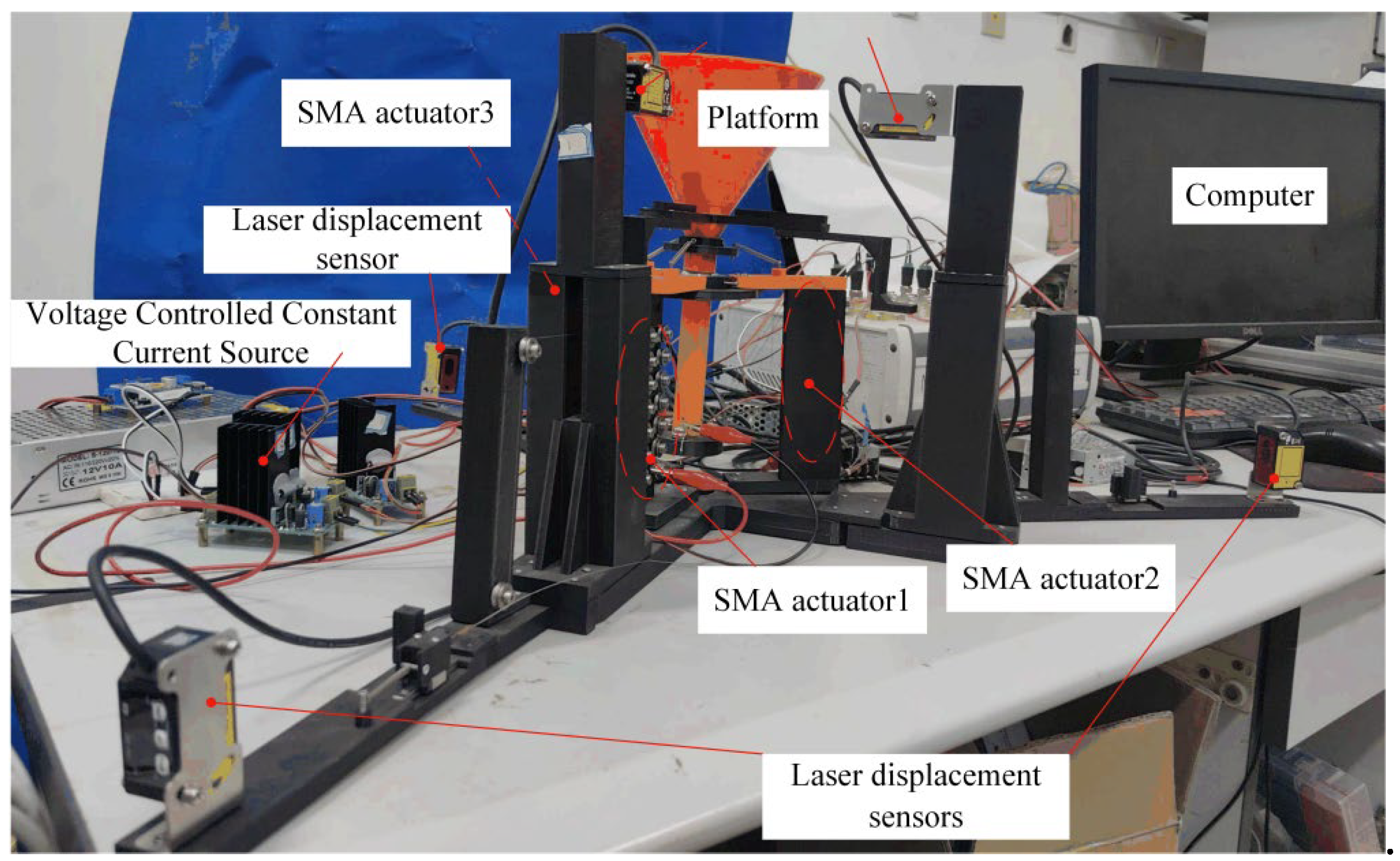
In order to realize the effective control of bi-directional swing motion of the SMA actuated parallel platform, a control system is built, as shown in Figure 2. It mainly consists of a nozzle simulation platform, ball bearings, a computer, dSPACE, five laser displacement sensors, three voltage-controlled constant current sources, and three SMA actuators. When viewed from the platform's top, the SMA actuators are arranged 120°apart from each other and marked as 1, 2, and 3 in the counterclockwise direction. Three of the five laser displacement sensors in the system are used to measure the linear displacement generated by the SMA actuators, and the other two are used to measure the swing angles of the nozzle indirectly.
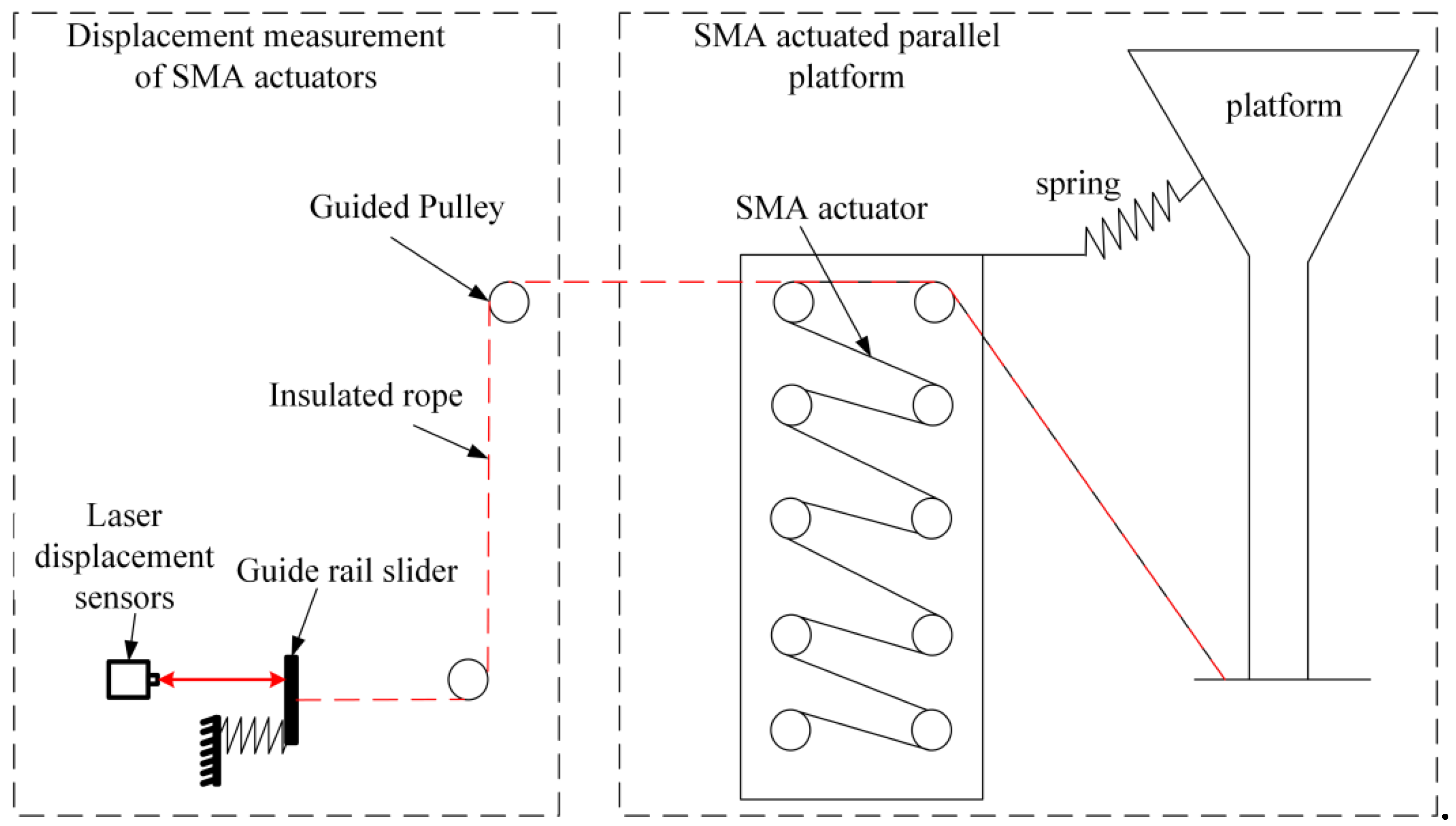
The displacement measurement principle of the SMA actuator on the platform is shown in Figure 3. When the SMA actuators make the nozzle swing, the slider of the rail connected to the platform by the insulated cable makes movement, and the displacement values measured by the laser displacement sensors are the displacement values of the SMA actuators at that time.
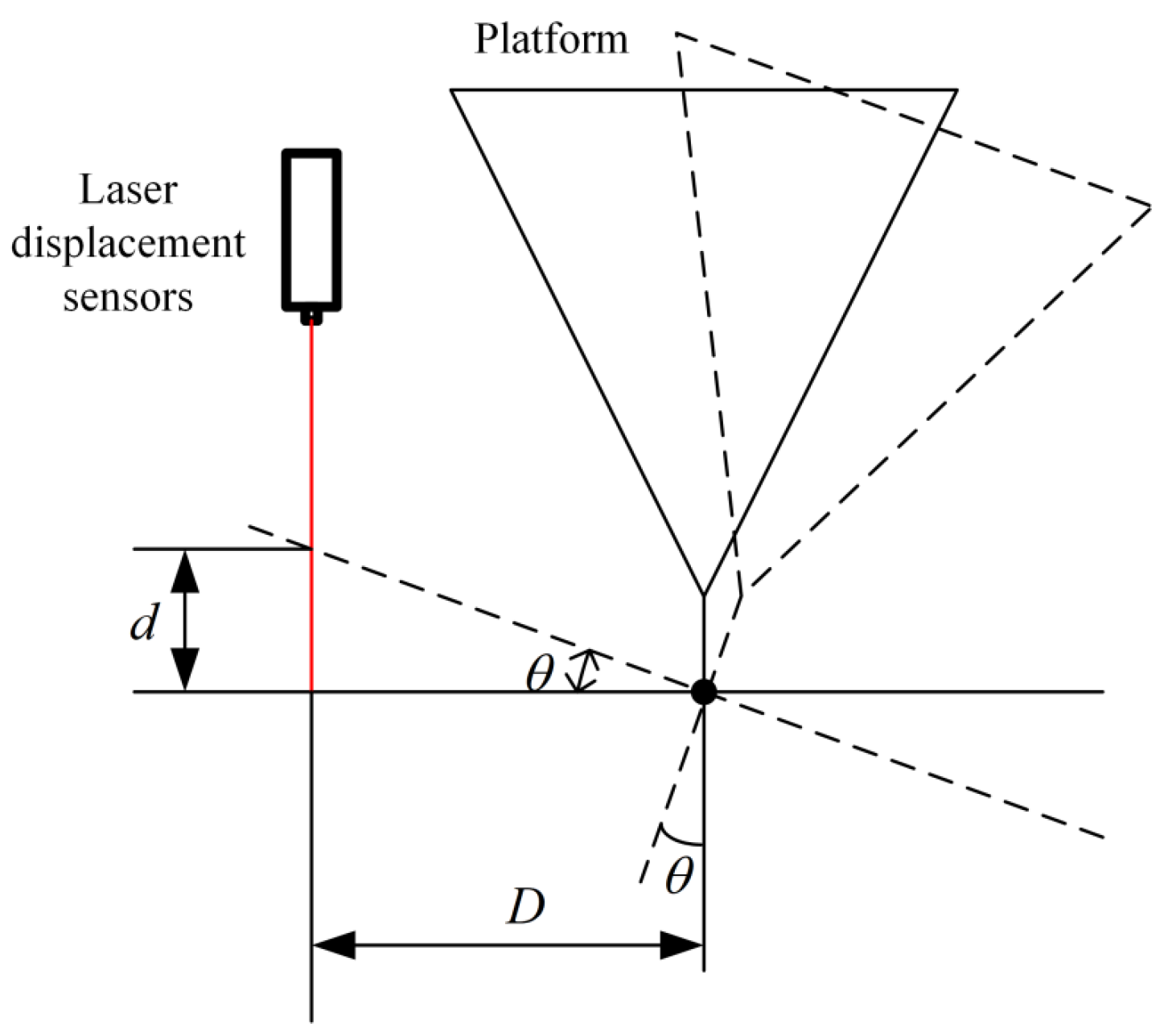
The swing angle measurement principle of the indirect measurement is shown in Figure 4. The relationship between the swing angle and the displacement value measured by the sensor is as follows:
θ = arctan ( d D ) .
4.2 Experiment results
In order to evaluate the control effect of the MFA-SMC method, the proposed control method is used to make the platform complete the motion control of bi-directional swing, respectively. The motion trajectory formed by the O4 point is selected as the reference curve to derive the expected trajectory of the swing angles α and β when the SMA actuated parallel platform performs bi-directional swing motion.
When the SMA actuated parallel platform performs bi-directional swing motion, there are three different cases.
Case (1): the trajectory of the O4 point ( x 4 , y 4 , z 4 ) is in the plane where SMA actuator 1 is located;
Case (2): the trajectory of the O4 point ( x 4 , y 4 , z 4 ) is in the plane where SMA actuator 2 is located;
Case (3): the trajectory of the O4 point ( x 4 , y 4 , z 4 ) is in the plane where SMA actuator 3 is located.
The following are the experimental results for different cases.
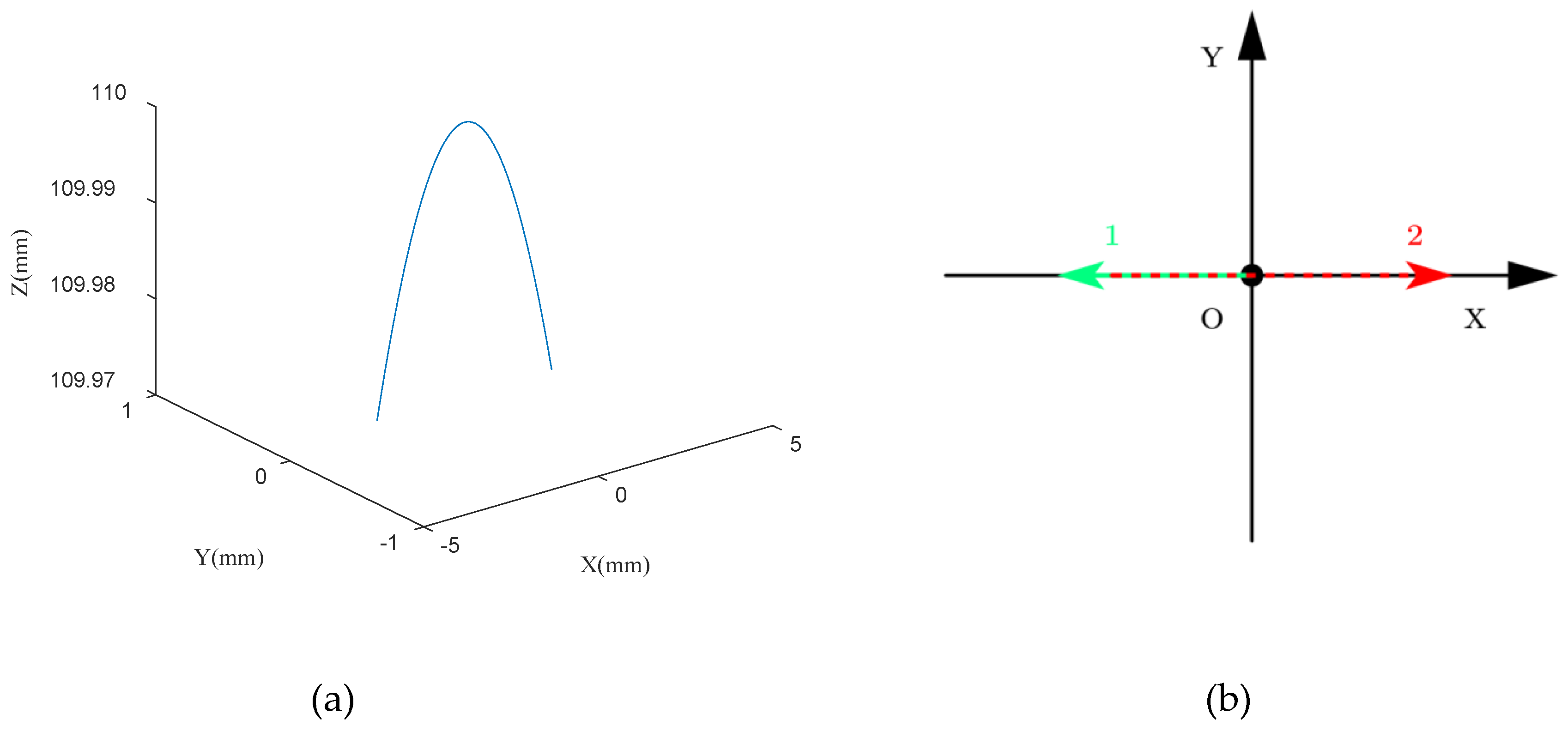
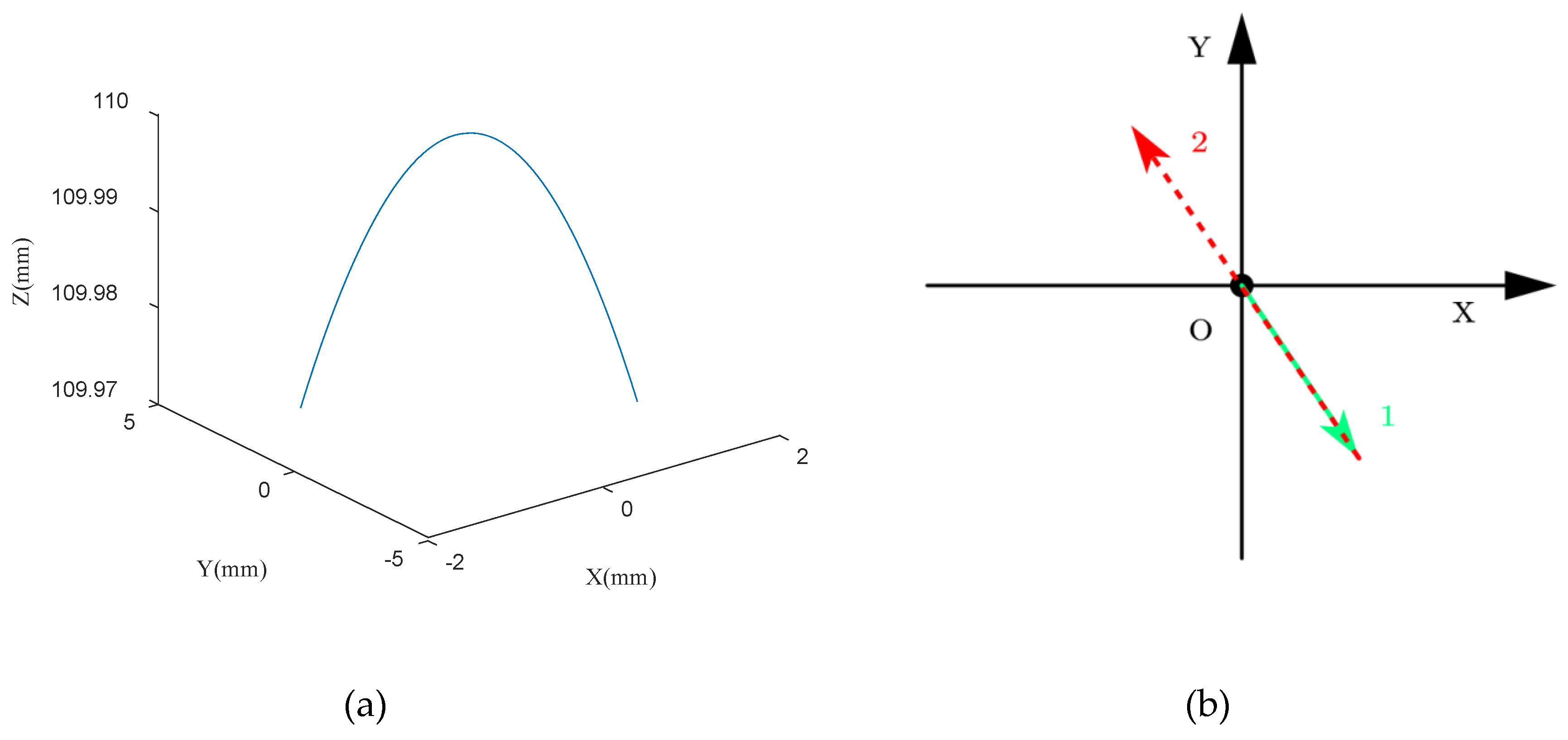
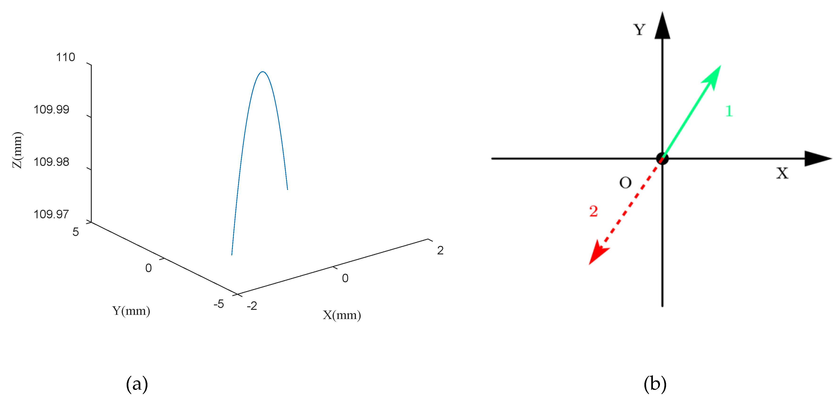
For case (1), the trajectory simulation curves of the O4 point in 3D coordinates and its projection on the OXY plane are shown in Figure 5 (a) and (b), respectively. The green line (labeled 1) in Figure 5(b) indicates the first moving trajectory of the O4 point, and then the O4 point moves along the red line (labeled 2) and then repeats.
In this case, the trajectory of bi-directional swing motion is generated according to the following steps:
① The O4 point is moved from the center to the edge, and the coordinates change as follows: y 4 = 0 , x 4 : 0 L , and z 4 = 110 2 x 4 2 .
② The O4 point is moved back to the other side, and the coordinates change as follows: y 4 = 0 , x 4 : L L , and z 4 = 110 2 x 4 2 .
③ The above steps are repeated to achieve bi-directional swing motion.
In the experiment, the parameters of the MFA-SMC method are set as follows: η = 0.8 , μ = 0.5 , q = 0.8 , and ε = 0.01 .
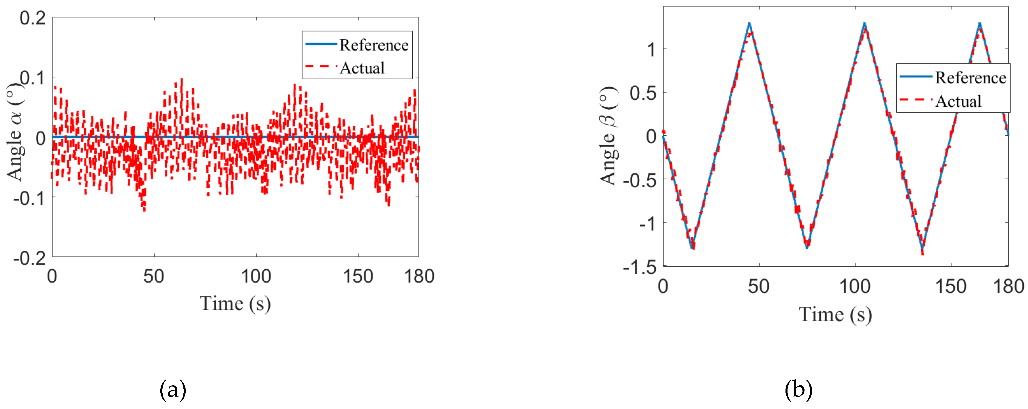
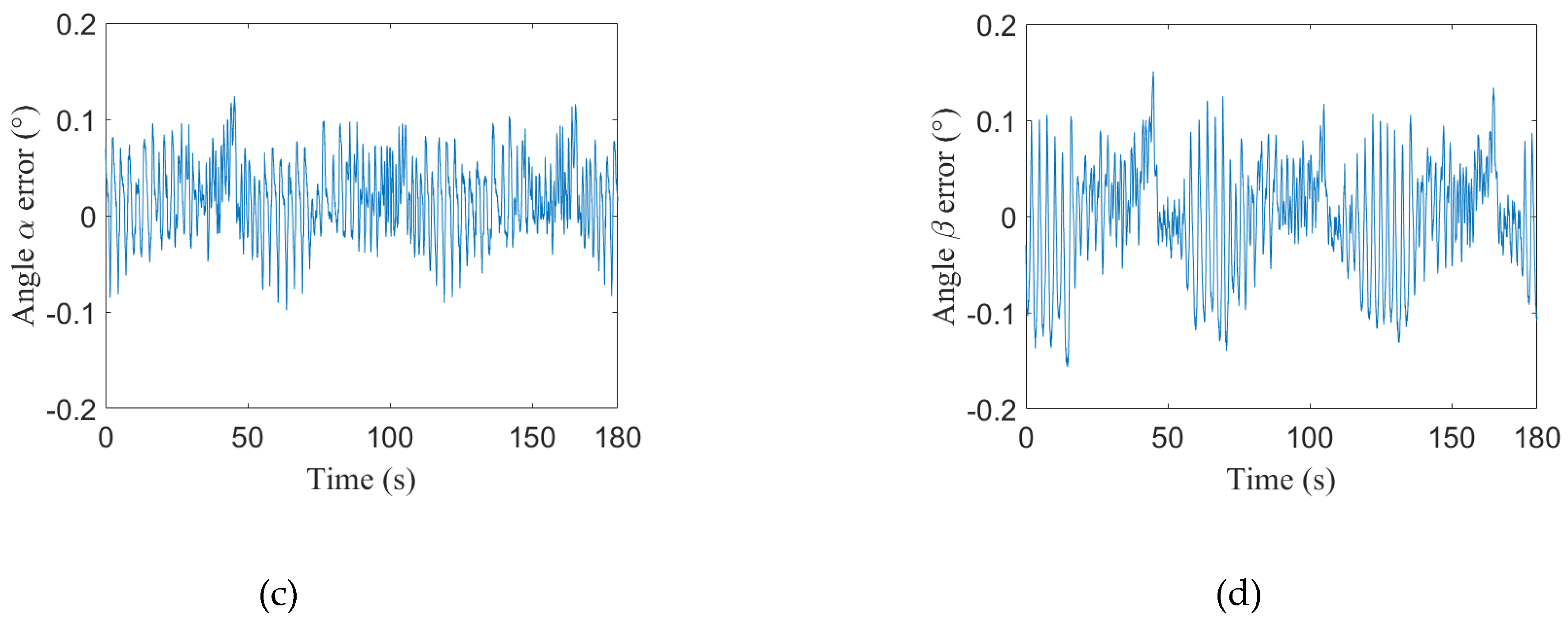
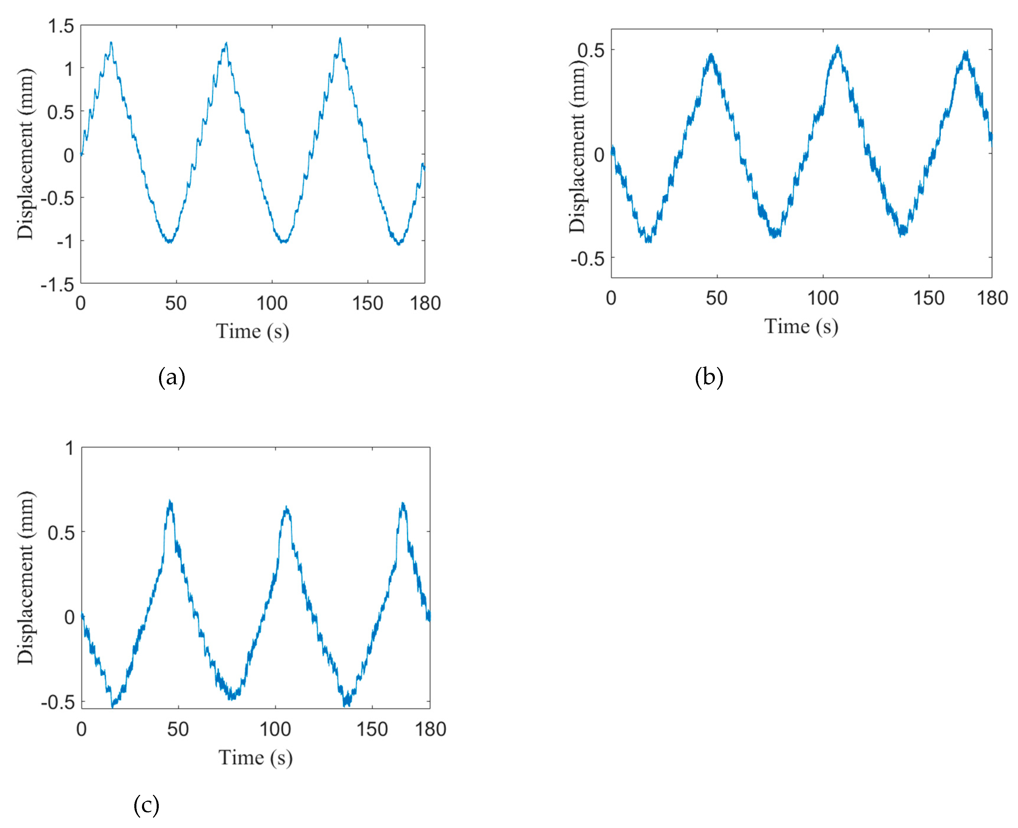
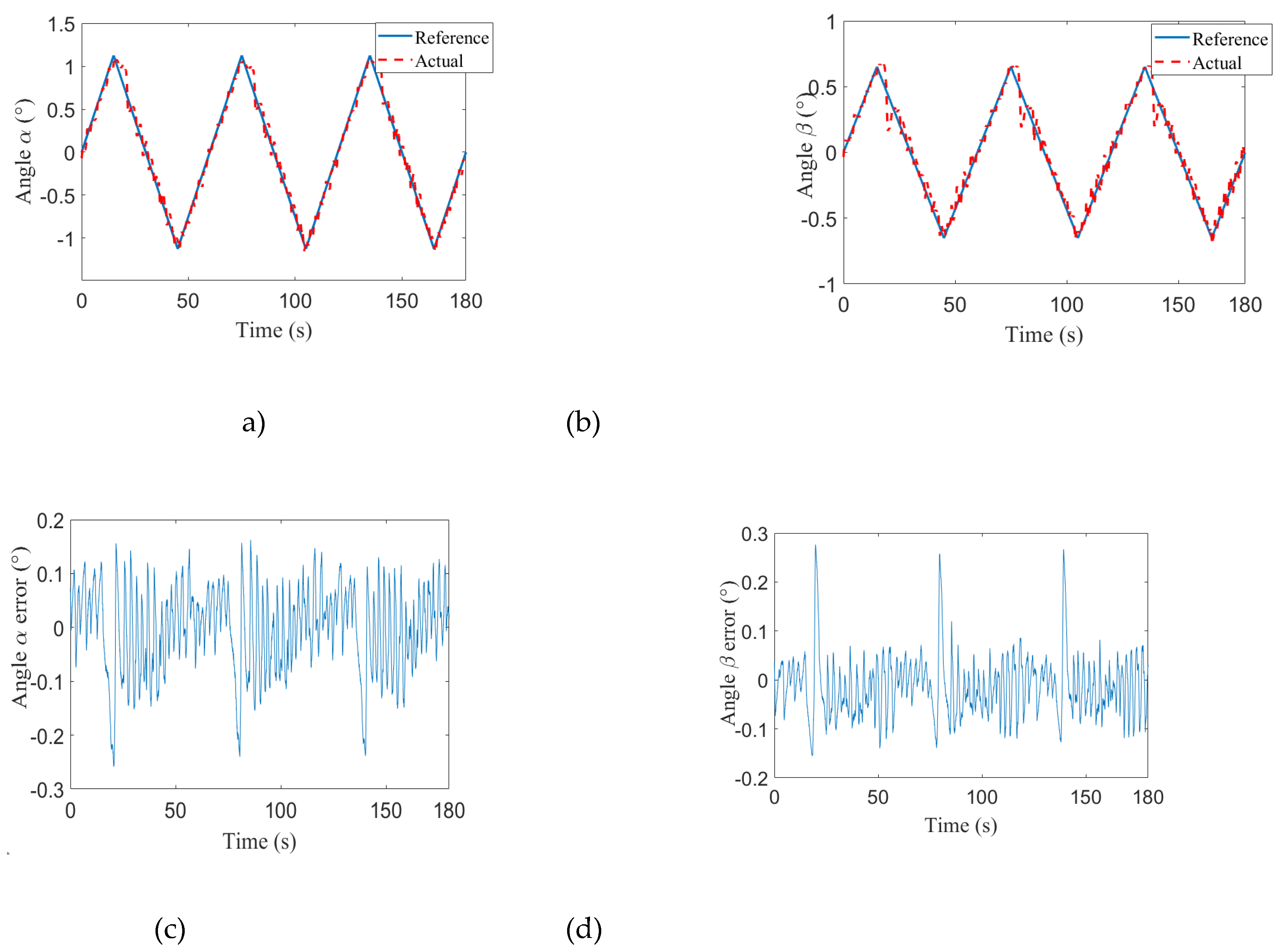
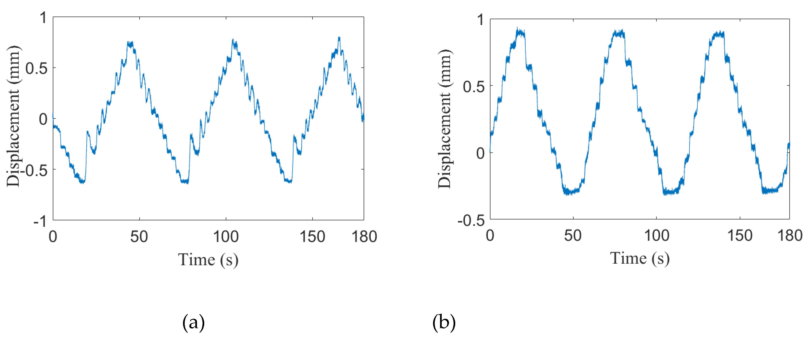
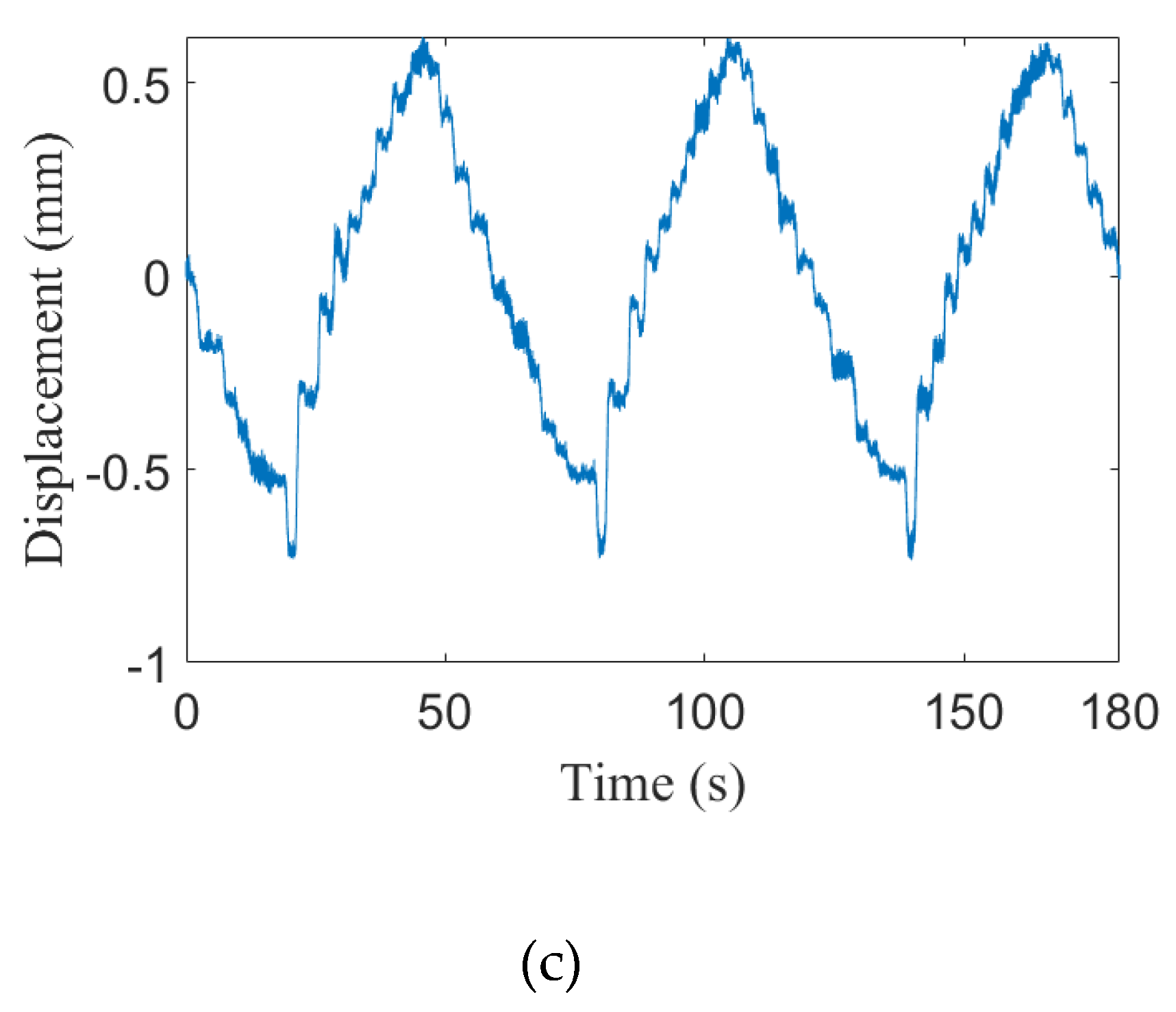
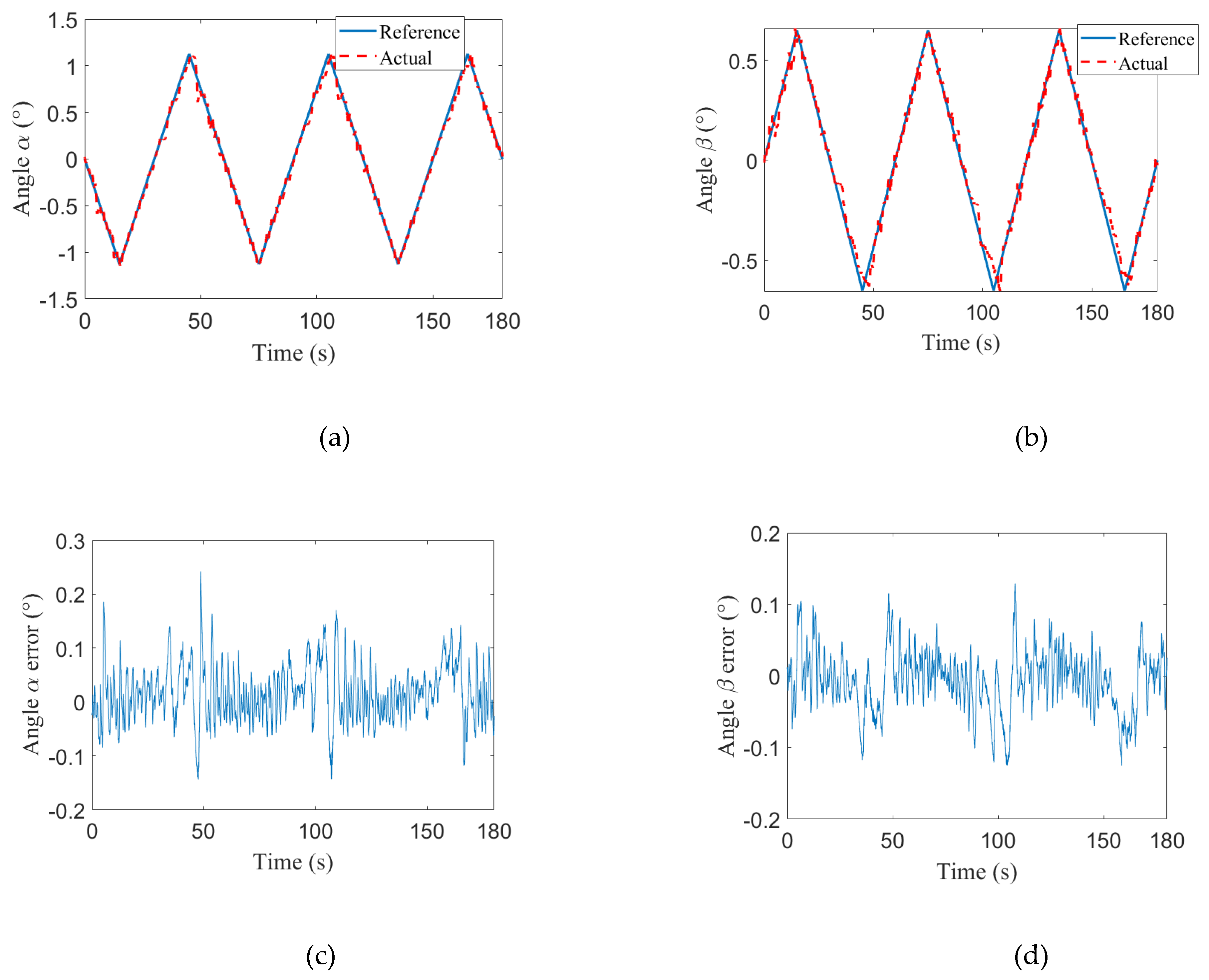
The experimental results obtained by applying the MFA-SMC method are shown in Figure 6 and Figure 7. (a), (b), (c) and (d) in Figure 6 show the tracking curves and error curves of the swing angles, and (a), (b) and (c) in Figure 7 show the displacement curves of the three SMA actuators. From Figure 6, it can be seen that after applying this method, by controlling the motion of the three SMA actuators separately, the proposed method can effectively track the reference curves of the swing angles α and β to realize bi-directional swing motion of the platform.
From the experimental results in Figure 7 (a), (b) and (c), it can be seen that in this case, the motion of the three SMA actuators is as follows: SMA actuator 1 first produces a positive displacement, i.e., SMA actuator 1 contracts, and the displacements of SMA actuators 2 and 3 are negative, i.e., SMA actuators are stretched. Currently, the SMA actuated parallel platform performs the trajectory motion of the green line (labeled 1) in Figure 5(b). When the displacement of SMA actuator 1 reaches the first wave crest and turns to the wave trough, the platform starts to carry out the trajectory of the red line (labeled 2) in Figure 5(b). After the displacement of SMA actuator 1 reaches the wave trough, it moves back toward the wave crest again, and SMA actuators 2 and 3 perform the opposite motion. The above process is repeated continuously to complete bi-directional swing motion of the platform.
For case (2), the trajectory simulation curves of the O4 point in 3D coordinates and its projection on the OXY plane are shown in Figure 8 (a) and (b), respectively. The green line (labeled 1) in Figure 8(b) indicates the first moving trajectory of the O4 point, and then the O4 point moves along the red line (labeled 2) and then repeats.
In this case, the trajectory of bi-directional swing motion is generated according to the following steps:
① The O4 point is moved from the center to the edge, and the coordinates change as follows: x 4 : 0 1 2 L , y 4 = 3 x 4 , and z 4 = 110 2 x 4 2 y 4 2 .
② The O4 point is moved back to the other side, and the coordinates change as follows: x 4 : 1 2 L 1 2 L , y 4 = 3 x 4 , and z 4 = 110 2 x 4 2 y 4 2 .
③ The above steps are repeated to achieve bi-directional swing motion.
In the experiment, the parameters of the MFA-SMC method are set as follows: η = 0.9 , μ = 0.6 , q = 0.8 , and ε = 0.01 .
The experimental results obtained by applying the MFA-SMC method are shown in Figure 9 and Figure 10. (a), (b), (c), and (d) in Figure 9 show the tracking curves and error curves of the swing angles, and (a), (b), and (c) in Figure 10 show the displacement curves of the three SMA actuators. From Figure 9, it can be seen that after applying this method, by controlling the motion of the three SMA actuators separately, the proposed control method can effectively track the reference curves of the swing angles α and β to realize bi-directional swing motion of the platform.
From the experimental results in Figure 10, it can be seen that in this case, the motion of the three SMA actuators is as follows: SMA actuator 2 first produces a positive displacement, i.e., SMA actuator 2 contracts, and the displacements of SMA actuators 1 and 3 are negative, i.e., SMA actuators are stretched. Currently, the SMA actuated parallel platform performs the trajectory motion of the green line (labeled 1) in Figure 8(b). When the displacement of SMA actuator 2 reaches the first wave crest and turns to the wave trough, the platform starts to carry out the trajectory of the red line (labeled 2) in Figure 8(b). After the displacement of SMA actuator 2 reaches the wave trough, it moves back toward the wave crest again. The above process is repeated continuously to complete bi-directional swing motion of the platform.
For case (3), the trajectory simulation curves of the O4 point in 3D coordinates and its projection on the OXY plane are shown in Figure 11 (a) and (b), respectively. The green line (labeled 1) in Figure 11(b) indicates the first moving trajectory of the O4 point, and then the O4 point moves along the red line (labeled 2) and then repeats.
In this case, the trajectory of bi-directional swing motion is generated according to the following steps:
① The O4 point is moved from the center to the edge, and the coordinates change as follows: x 4 : 0 1 2 L , y 4 = 3 x 4 , and z 4 = 110 2 x 4 2 y 4 2 .
② The O4 point is moved back to the other side, and the coordinates change as follows: x 4 : 1 2 L 1 2 L , y 4 = 3 x 4 , and z 4 = 110 2 x 4 2 y 4 2 .
③ The above steps are repeated to achieve bi-directional swing motion.
In the experiment, the parameters of the MFA-SMC method are set as follows: η = 0.7 , μ = 0.6 , q = 0.7 , and ε = 0.01 .
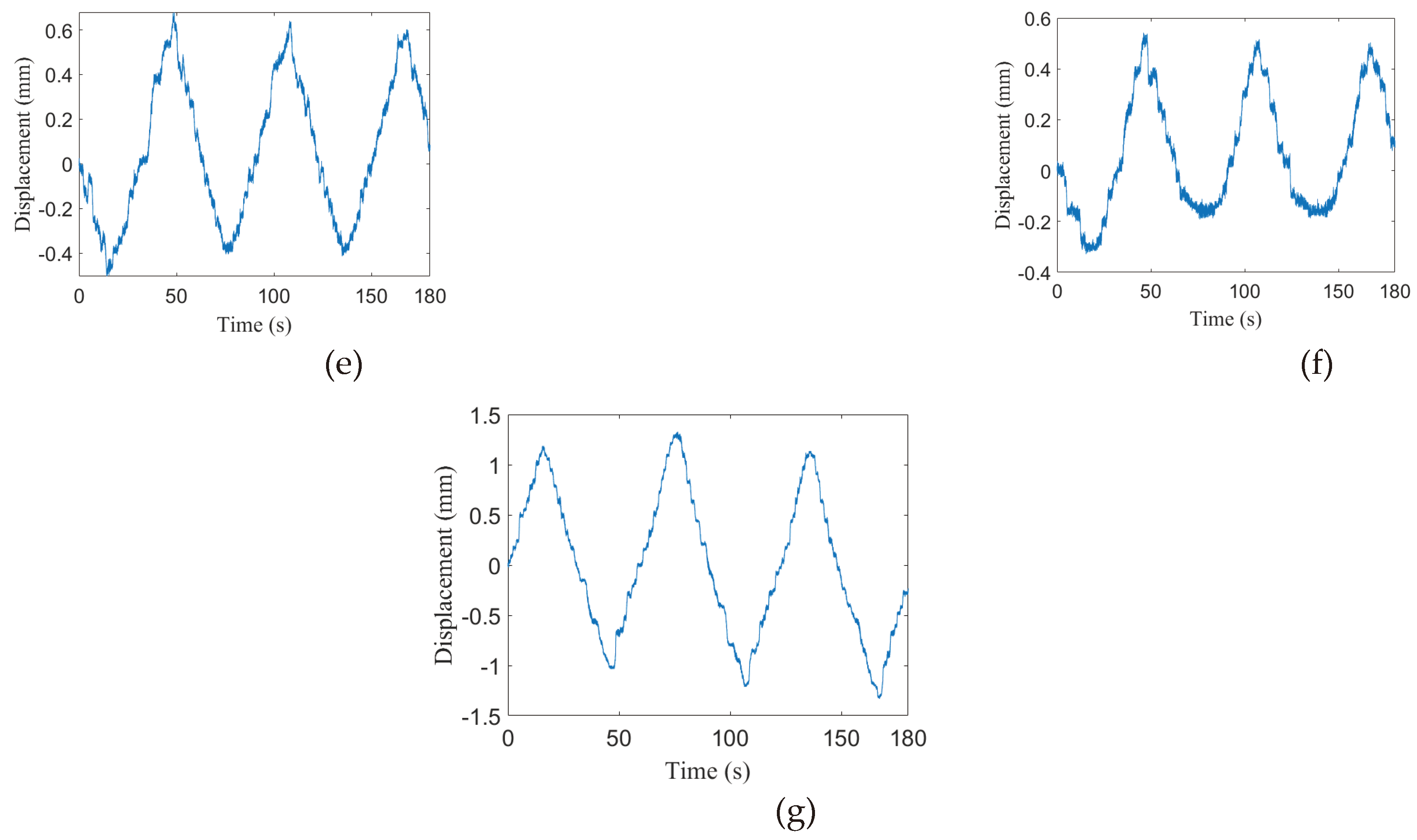
The experimental results obtained by applying the MFA-SMC method are shown in Figure 12 and Figure 13. (a), (b), (c), and (d) in Figure 12 show the tracking curves and error curves of the swing angles, and (a), (b), and (c) in Figure 13 show the displacement curves of the three SMA actuators. From Figure 12, it can be seen that after applying this method, by controlling the motion of the three SMA actuators separately, the proposed method can effectively track the reference curves of the swing angles α and β to realize bi-directional swing motion of the platform.
From Figure 13, it can be seen that in this case, SMA actuator 3 first produces a positive displacement, i.e., SMA actuator 3 contracts, and the displacements of SMA actuators 1 and 2 are negative, i.e., SMA actuators are stretched. At this time, the SMA actuated parallel platform performs the trajectory motion in the direction of labeled 1 (green arrow line) in Figure 11(b). When the displacement of SMA actuator 2 reaches the first wave crest and turns to the wave trough, this means that the platform starts to perform the trajectory in the direction of labeled 2 (red arrow line) in Figure 11(b). It then performs the motion to the next cycle, and so on and so forth, to realize bi-directional swing motion of the SMA actuated parallel platform in the plane where the SMA actuator 3 is located.
The quantitative index, mean absolute errors (MAEs) are used to evaluate the proposed control algorithms, and the specific results are shown in Table 1. It can be seen from Table 1 that the MFA-SMC method obtains a small MAE in all three bi-directional swing forms, i.e., the MFA-SMC method is able to obtain the desired tracking accuracy.
In conclusion, both the inverse model-based PID control method and the MFA-SMC method can effectively realize the control of bi-directional swing motion of the SMA actuated parallel platform under different conditions. But compared with the inverse model-based PID control method, the MFA-SMC method can obtain a better control effect and does not need to establish the inverse kinematic model of the platform. In addition, the inverse model-based PID control method needs five laser displacement sensors, while the MFA-SMC method needs only two laser displacement sensors. Hence, the MFA-SMC method uses fewer sensors and can further save the overall hardware cost.

5. Conclusion

The MFA-SMC algorithm is designed for a bi-directional swing the MIMO system in SMA actuated parallel platform. In the process of designing the MFA-SMC algorithm, the multiple input and multiple output model-free adaptive control method is first introduced, and the model-free adaptive sliding mode controller is designed by combining the sliding mode control theory, and the closed-loop stability of the proposed controller is analyzed by the Lyapunov method. Finally, it is verified by experiments that the proposed model-free adaptive sliding mode control method can control the platform to achieve bi-directional swing, and the control algorithm avoids the work of establishing an inverse kinematic model and can ensure a low tracking error and obtain a great control effect.

Acknowledgements

This work was supported by the National Natural Science Foundation of China under grant number 62073063.

References

  1. Jani, J.M.; Leary, M.; Subic, A.; Gibson, M.A. A review of shape memory alloy research, applications and opportunities. Materials & Design 2014, 56, 1078–1113. [Google Scholar]
  2. Zhang, J.; Sheng, J.; O’Neill, C.T.; et al. Robotic artificial muscles: Current progress and future perspectives[J]. IEEE Transactions on Robotics 2019, 35, 761–781. [Google Scholar] [CrossRef]
  3. Hao, Y.; Zhang, S.; Fang, B.; et al. A Review of Smart Materials for the Boost of Soft Actuators, Soft Sensors, and Robotics Applications[J]. Chinese Journal of Mechanical Engineering 2022, 35, 1–16. [Google Scholar] [CrossRef]
  4. Morgan, N.B. Medical shape memory alloy applications—the market and its products[J]. Materials Science & Engineering A 2004, 378, 16–23. [Google Scholar]
  5. Gómez-Espinosa, A.; Castro Sundin, R.; Loidi Eguren, I.; Cuan-Urquizo, E.; Treviño-Quintanilla, C.D. Neural network direct control with online learning for shape memory alloy manipulators. Sensors 2019, 19, 2576. [Google Scholar] [CrossRef] [PubMed]
  6. Li, J.; Sun, M.; Wu, Z.; Yin, H. Design, analysis, and grasping experiments of a novel soft hand: hybrid actuator using shape memory alloy actuators, motors, and electromagnets. Soft Robotics 2020, 7, 396–407. [Google Scholar] [CrossRef] [PubMed]
  7. Simons, M.F.; Digumarti, K.M.; Le, N.H.; Chen, H.Y.; Carreira, S.C.; Zaghloul, N.S.; Rossiter, J. B: Ionic Glove: A soft smart wearable sensory feedback device for upper limb robotic prostheses. IEEE Robotics and Automation Letters 2021, 6, 3311–3316. [Google Scholar] [CrossRef]
  8. Bellini, A.; Colli, M.; Dragoni, E. Mechatronic design of a shape memory alloy actuator for automotive tumble flaps: a case study. ieee transactions on industrial electronics 2009, 56, 2644–2656. [Google Scholar] [CrossRef]
  9. Gradin, H.; Braun, S.; Stemme, G.; van der Wijngaart, W. SMA microvalves for very large gas flow control manufactured using wafer-level eutectic bonding. IEEE Transactions on Industrial Electronics 2011, 59, 4895–4906. [Google Scholar] [CrossRef]
  10. Bena, R.M.; Nguyen, X.T.; Calderón, A.A.; Rigo, A.; Pérez-Arancibia, N.O. SMARTI: A 60-mg Steerable Robot Driven by High-Frequency Shape-Memory Alloy Actuation. IEEE Robotics and Automation Letters 2021, 6, 8173–8180. [Google Scholar] [CrossRef]
  11. Arai, K.; Aramaki, S.; Yanagisawa, K. (1995, July). Feedback linearization for SMA (shape memory alloy). In SICE'95. Proceedings of the 34th SICE Annual Conference. International Session Papers (pp. 1383-1386). IEEE.
  12. Moallem, M.; Tabrizi, V.A. Tracking control of an antagonistic shape memory alloy actuator pair. IEEE Transactions on control systems technology 2008, 17, 184–190. [Google Scholar] [CrossRef]
  13. Ianagui, A.; Tannuri, E.A. A sliding mode torque and position controller for an antagonistic SMA actuator. Mechatronics 2015, 30, 126–139. [Google Scholar] [CrossRef]
  14. Kumagai, A.; Liu, T.I.; Hozian, P. Control of shape memory alloy actuators with a neuro-fuzzy feedforward model element[J]. Journal of Intelligent Manufacturing 2006, 17, 45–56. [Google Scholar] [CrossRef]
  15. Li, J.; Tian, H. Position control of SMA actuator based on inverse empirical model and SMC-RBF compensation[J]. Mechanical Systems and Signal Processing 2018, 108, 203–215. [Google Scholar] [CrossRef]
  16. Jin, M.; Lee, J.; Ahn, K.K. Continuous nonsingular terminal sliding-mode control of shape memory alloy actuators using time delay estimation. IEEE/ASME Transactions on Mechatronics 2014, 20, 899–909. [Google Scholar] [CrossRef]
  17. Romano, R.; Tannuri, E.A. Modeling, control and experimental validation of a novel actuator based on shape memory alloys[J]. Mechatronics 2009, 19, 1169–1177. [Google Scholar] [CrossRef]
  18. Zhang, B.; Zhao, X.G.; Li, X.G.; et al. Robust indirect adaptive control for a class of nonlinear systems and its application to shape memory alloy actuators[J]. IEEE Access 2018, 6, 35809–35823. [Google Scholar] [CrossRef]
  19. Kha, N.B.; Ahn, K.K. Position control of shape memory alloy actuators by using self tuning fuzzy PID controller[C]//2006 1ST IEEE Conference on Industrial Electronics and Applications. IEEE, 2006: 1-5.
  20. Song, G.; Ma, N. Control of shape memory alloy actuators using pulse-width pulse-frequency (PWPF) modulation[J]. Journal of intelligent material systems and structures 2003, 14, 15–22. [Google Scholar] [CrossRef]
  21. Villoslada, Á.; Escudero, N.; Martín, F.; et al. Position control of a shape memory alloy actuator using a four-term bilinear PID controller[J]. Sensors and Actuators A: Physical 2015, 236, 257–272. [Google Scholar] [CrossRef]
  22. Tai, N.T.; Ahn, K.K. Output feedback direct adaptive controller for a SMA actuator with a Kalman filter[J]. IEEE Transactions on control systems technology 2011, 20, 1081–1091. [Google Scholar] [CrossRef]
  23. Dominik, I. Type-2 fuzzy logic controller for position control of shape memory alloy wire actuator[J]. Journal of Intelligent Material Systems and Structures 2016, 27, 1917–1926. [Google Scholar] [CrossRef]
  24. Kuntanapreeda, S. Adaptive Fuzzy Sliding-Mode Position Control of A Shape Memory Alloy Actuated System[C]//Applied Mechanics and Materials. Trans Tech Publications Ltd, 2015, 789, 946–950. [Google Scholar]
  25. Elwaleed, A.K.; Mohamed, N.A.; Nor MJ, M.; et al. A new method for actuating parallel manipulators[J]. Sensors and Actuators A: Physical 2008, 147, 593–599. [Google Scholar] [CrossRef]
  26. Copaci, D.; Muñoz, J.; González, I.; et al. SMA-Driven Soft Robotic Neck: Design, Control and Validation[J]. IEEE Access 2020, 8, 199492–199502. [Google Scholar] [CrossRef]
  27. Qiu, C.; Zhang, K.; Dai, J.S. Constraint-based design and analysis of a compliant parallel mechanism using SMA-spring actuators[C]//International Design Engineering Technical Conferences and Computers and Information in Engineering Conference. American Society of Mechanical Engineers 2014, 46360, V05AT08A035. [Google Scholar]
  28. Liu, W.; Jing, Z.; Pan, H.; et al. Distance-directed target searching for a deep visual servo sma driven soft robot using reinforcement learning[J]. Journal of Bionic Engineering 2020, 17, 1126–1138. [Google Scholar] [CrossRef]
  29. Cheng, C.; Cheng, J.; Huang, W. Design and development of a novel SMA actuated multi-DOF soft robot[J]. IEEE Access 2019, 7, 75073–75080. [Google Scholar] [CrossRef]
  30. Pillai, R.R.; Ganesan, M. Mechatronics design and kinematic analysis of SMA spring actuated parallel manipulator[C]//Journal of Physics: Conference Series. IOP Publishing 2021, 1969, 012011. [Google Scholar]
  31. Hou, Z.; Jin, S. Data-driven model-free adaptive control for a class of MIMO nonlinear discrete-time systems[J]. IEEE transactions on neural networks 2011, 22, 2173–2188. [Google Scholar] [PubMed]
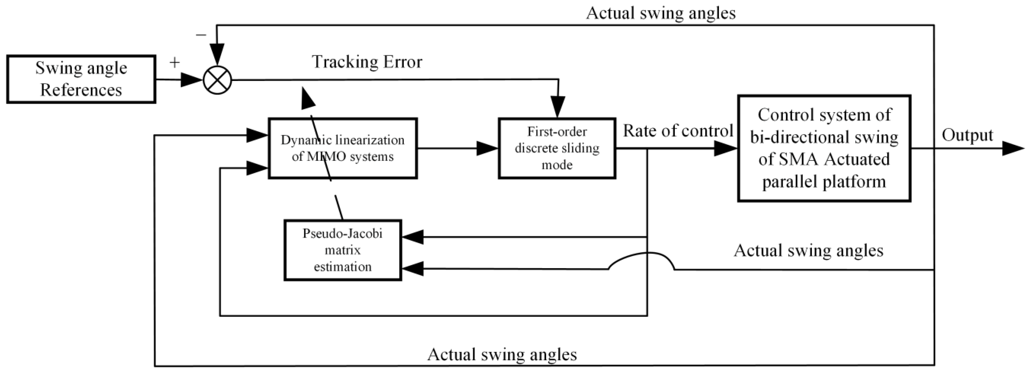
Figure 1. Principle of MFA-SMC.
Preprints 103320 g001
Figure 2. Two-way swing control system of SMA micro vector simulation platform.
Preprints 103320 g002
Figure 3. Displacement measurement principle of SMA actuator.
Preprints 103320 g003
Figure 4. Schematic diagram of swing angle measurement.
Preprints 103320 g004
Figure 5. Track simulation diagram from different perspectives. (a) The trajectory curve in the three-dimensional coordinates of O4 point, (b) Projection of O4 point trajectory on OXY plane.
Preprints 103320 g005
Figure 6. Experimental results of MFA-SMC method. (a) Swing angle α , (b) Swing angle β , (c) Swing angle α error, (d) Swing angle β error.
Preprints 103320 g006aPreprints 103320 g006b
Figure 7. Experimental results of MFA-SMC method. (a) Displacement of SMA actuator 1, (b) Displacement of SMA actuator 2, (c) Displacement of SMA actuator 3.
Preprints 103320 g007
Figure 8. Track simulation diagram from different perspectives. (a) The trajectory curve in the three-dimensional coordinates of O4 point, (b) Projection of O4 point trajectory on OXY plane.
Preprints 103320 g008
Figure 9. Experimental results of MFA-SMC method. (a) Swing angle α , (b) Swing angle β , (c) Swing angle α error, (d) Swing angle β error.
Preprints 103320 g009
Figure 10. Experimental results of MFA-SMC method. (a) Displacement of SMA actuator 1, (b) Displacement of SMA actuator 2, (c) Displacement of SMA actuator 3.
Preprints 103320 g010aPreprints 103320 g010b
Figure 11. Track simulation diagram from different perspectives.(a) The trajectory curve in the three-dimensional coordinates of O4 point, (b) Projection of O4 point trajectory on OXY plane.
Preprints 103320 g011
Figure 12. Experimental results of MFA-SMC method. (a) Swing angle α , (b) Swing angle β , (c) Swing angle α error, (d) Swing angle β error.
Preprints 103320 g012
Figure 13. Experimental results of MFA-SMC method. (e) Displacement of SMA actuator 1, (f) Displacement of SMA actuator 2, (g) Displacement of SMA actuator 3.
Preprints 103320 g013
Table 1. Mean absolute errors of angles.
Angles α
Swing mode β
1 0.0340° 0.0447°
2 0.0629° 0.0465°
3 0.0423° 0.0323°
Disclaimer/Publisher’s Note: The statements, opinions and data contained in all publications are solely those of the individual author(s) and contributor(s) and not of MDPI and/or the editor(s). MDPI and/or the editor(s) disclaim responsibility for any injury to people or property resulting from any ideas, methods, instructions or products referred to in the content.
Copyright: This open access article is published under a Creative Commons CC BY 4.0 license, which permit the free download, distribution, and reuse, provided that the author and preprint are cited in any reuse.
Prerpints.org logo

Preprints.org is a free preprint server supported by MDPI in Basel, Switzerland.

Subscribe

© 2024 MDPI (Basel, Switzerland) unless otherwise stated