Submitted:
08 April 2024
Posted:
09 April 2024
You are already at the latest version
Abstract
Keywords:
1. Introduction
2. Materials and Methods
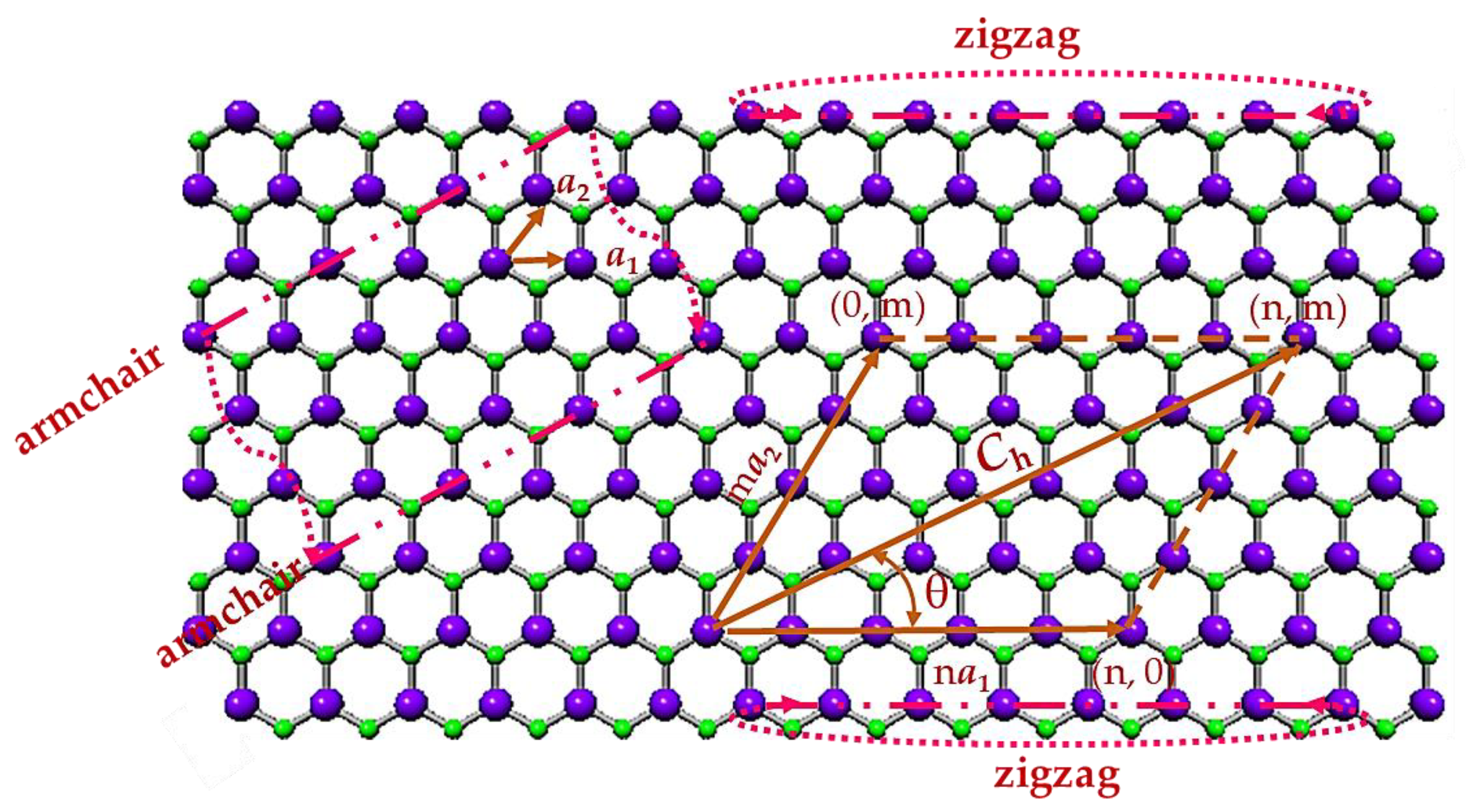
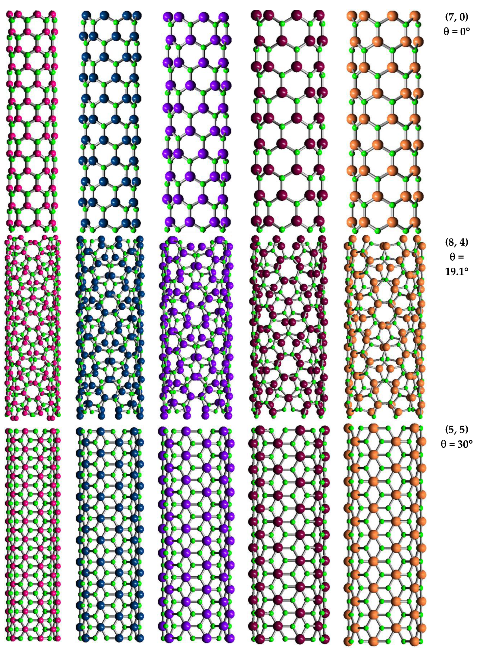
2.1. Atomic Structure of 13th Group Element – Nitride Nanotubes
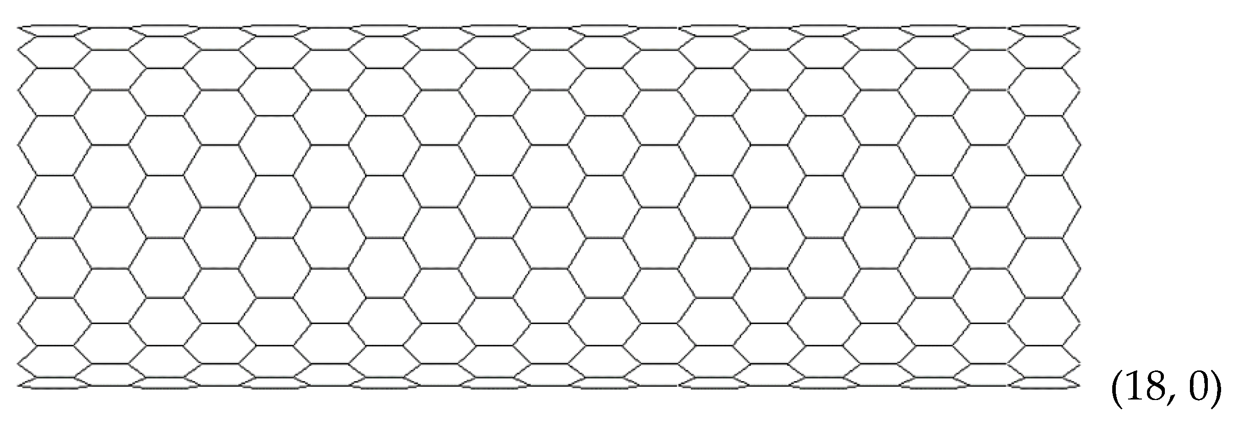
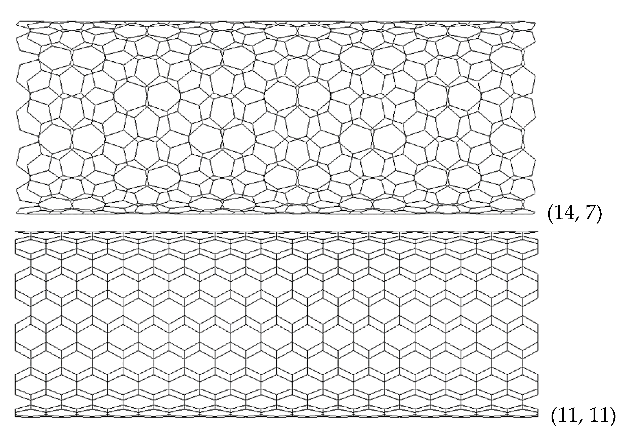
2.2. Geometrical Characteristics and Finite Element Modeling of the Elastic Behaviour of SWBNNTs, SWAlNNTs, SWGaNNTs, SWInNNTs and SWTlNNTs
2.3. Elastic Properties of SWBNNTs, SWAlNNTs, SWGaNNTs, SWInNNTs and SWTlNNTs
3. Results and Discussion: Elastic Properties of SWBNNTs, SWAlNNTs, SWGaNNTs, SWInNNTs and SWTlNNTs
3.1. Rigidities
3.2. Surface Young´s Modulus
3.3. Surface Shear Modulus and Poisson´s Ratio
4. Conclusions
Author Contributions
Funding
Informed Consent Statement
Data Availability Statement
Conflicts of Interest
References
- Ye, C.; Peng, Q. Mechanical Stabilities and Properties of Graphene-like 2D III-Nitrides: A Review. Crystals 2023, 13, 12. [Google Scholar] [CrossRef]
- Zheng, F.; Xiao, X.; Xie, J.; Zhou, L.; Li, Y.; Dong, H. Structures, properties and applications of two-dimensional metal nitrides: from nitride MXene to other metal nitrides. 2D Mater. 2022, 9, 022001. [Google Scholar] [CrossRef]
- Abdullah, N.R. .; Abdullah, B.J.; Gudmundsson, V. Electronic and optical properties of metallic nitride: A comparative study between the MN (M = Al, Ga, In, Tl) monolayers. Solid State Commun. 2022, 346, 114705. [Google Scholar] [CrossRef]
- Elahi, S.M.; Farzan, M.; Salehi, H.; Abolhasani, M.R. An investigation of electronic and optical properties of TlN nanosheet and compare with TlN bulk (Wurtzite) by first principle. Optik 2016, 127, 9367–9376. [Google Scholar] [CrossRef]
- Golberg, D.; Bando, Y.; Huang, Y.; Terao, T.; Mitome, M.; Tang, C.; Zhi, C. Boron nitride nanotubes and nanosheets. ACS Nano 2010, 4, 2979–2993. [Google Scholar] [CrossRef]
- Wang, Y.; Zhou, V.; Xie, Y.; Zheng, X.-Q.; Feng, P.X.-L. Optical contrast signatures of hexagonal boron nitride on a device platform. Opt. Mater. Express. 2019, 9, 1223–1232. [Google Scholar] [CrossRef]
- Song, L.; Ci, L.; Lu, H.; Sorokin, P.B.; Jin, C.; Ni, J.; Kvashnin, A.G.; Kvashnin, D.G.; Lou, J.; Yakobson, B.I.; Ajayan, P.M. Large scale growth and characterization of atomic hexagonal boron nitride layers. Nano Lett. 2010, 10, 3209–3215. [Google Scholar] [CrossRef]
- Vurgaftman, I.; Meyer, J.R. Band parameters for nitrogen-containing semiconductors. J. Appl. Phys. 2003, 94, 3675–3696. [Google Scholar] [CrossRef]
- Chattopadhyay, S.; Ganguly, A.; Chen, K.-H.; Chen, L.-Ch. One-Dimensional Group III-Nitrides: Growth, Properties, and Applications in Nanosensing and Nano-Optoelectronics. Crit. Rev. Solid State Mater. Sci. 2009, 34, 224–279. [Google Scholar] [CrossRef]
- Zaoui, A. Plane wave pseudopotential study of ground state properties and electrochemical description of thallium nitride. Mater. Sci. Eng.B 2003, 103, 258–261. [Google Scholar] [CrossRef]
- Li-Wei, S.; Yi-Feng, D.; Li-Xia, Q. Structural Stability and Elastic Properties of Wurtzite TlN under Hydrostatic Pressure. Chin. Phys. Lett. 2010, 27, 080505. [Google Scholar] [CrossRef]
- Walker, K.E.; Rance, G.A.; Pekker, A.; Tóháti, H.M.; Fay, M.W.; Lodge, R.W.; Stoppiello, C.T.; Kamarás, K.; Khlobystov, A.N. Growth of carbon nanotubes inside boron nitride nanotubes by coalescence of fullerenes: toward the world's smallest coaxial cable. Small Methods 2017, 1, 1700184. [Google Scholar] [CrossRef]
- Huang, Z.; Lü, T.-Y.; Wang, H.-Q.; Yang, S.-W.; Zheng, J.-C. Electronic and thermoelectric properties of the group-III nitrides (BN, AlN and GaN) atomic sheets under biaxial strains. Comput. Mater. Sci. 2017, 130, 232–241. [Google Scholar] [CrossRef]
- Amorim, B.; Cortijo, A.; de Juan, F.; Grushin, A.G.; Guinea, F.; Gutiérrez-Rubio, A.; Ochoa, H.; Parente, V.; Roldán, R.; San-José, P.; Schiefele, J.; Sturla, M.; Vozmediano, M.A.H. Novel effects of strains in graphene and other two dimensional materials. Phys. Rep. 2016, 617, 1–54. [Google Scholar] [CrossRef]
- Behzad, S. Effects of strain and thickness on the electronic and optical behaviors of two-dimensional hexagonal gallium nitride. Superlattices Microstruct. 2017, 106, 102–110. [Google Scholar] [CrossRef]
- Liu, P.; Sarkar, A.D.; Ahuja, R. Shear strain induced indirect to direct transition in band gap in AlN monolayer nanosheet. Comput. Mater. Sci. 2014, 86, 206–210. [Google Scholar] [CrossRef]
- Beshkova, M.; Yakimova, R. Properties and potential applications of two-dimensional AlN. Vacuum 2020, 176, 109231. [Google Scholar] [CrossRef]
- Chowdhury, R.; Adhikari, S. Boron-nitride nanotubes as zeptogram-scale bionanosensors: Theoretical investigations. IEEE Trans. Nanotechnol. 2011, 10, 659–667. [Google Scholar] [CrossRef]
- Noei, M.; Soleymanabadi, H.; Peyghan, A.A. Aluminum nitride nanotubes. Chem. Pap. 2017, 71, 881–893. [Google Scholar] [CrossRef]
- Albarakati, R.; Al-Qurashi, O.; Safi, Z.; Wazzan, N. A dispersion-corrected DFT calculation on encapsulation of favipiravir drug used as antiviral against COVID-19 into carbon-, boron-, and aluminum-nitride nanotubes for optimal drug delivery systems combined with molecular docking simulations. Struct Chem. 2023, 11, 1–19. [Google Scholar] [CrossRef]
- Liu, B.; Bando, Y.; Wang, M.; Tang, C.; Mitome, M.; Golberg, D. Crystallography and elasticity of individual GaN nanotubes. Nanotechnology 2009, 20, 185705. [Google Scholar] [CrossRef] [PubMed]
- Rubio, A.; Corkill, J.; Cohen, M.L. Theory of graphitic boron nitride nanotubes. Phys. Rev. B 1994, 49, 5081–5084. [Google Scholar] [CrossRef] [PubMed]
- Chowdhury, R.; Adhikari, S. Boron-nitride nanotubes as zeptogram-scale bionanosensors: Theoretical investigations. IEEE Trans. Nanotechnol. 2011, 10, 659–667. [Google Scholar] [CrossRef]
- Lourie, O.R.; Jones, C.R.; Bartlett, B.M.; Gibbons, P.C.; Ruoff, R.S.; Buhro, W.E. CVD growth of boron nitride nanotubes. Chem. Mater. 2000, 12, 1808–1810. [Google Scholar] [CrossRef]
- Ahmad, P.; Khandaker, M.U.; Khana, Z.R. Amina, Y.M. Synthesis of boron nitride nanotubes via chemical vapour deposition: a comprehensive review. RSC Adv. 2015, 5, 35116–35137. [Google Scholar] [CrossRef]
- Kim, J.; Lee, S.; Uhm, Y.R.; Jun, J.; Rhee, C.K.; Kim, G.M. Synthesis and growth of boron nitride nanotubes by a ball milling–annealing process. Acta Mater. 2011, 59, 2807–2813. [Google Scholar] [CrossRef]
- Golberg, D.; Bando, Y.; Eremets, M.; Takemura, K.; Kurashima, K.; Yusa, H. Nanotubes in boron nitride laser heated at high pressure. Appl. Phys. Lett. 1996, 69, 2045–2047. [Google Scholar] [CrossRef]
- Kim, K.S.; Couillard, M.; Shin, H.; Plunkett, M.; Ruth, D.; Kingston, C.T.; Simard, B. Role of hydrogen in high-yield growth of boron nitride nanotubes at atmospheric pressure by induction thermal plasma. ACS Nano 2018, 12, 884–893. [Google Scholar] [CrossRef]
- Zhang, D.; Zhang, R. Theoretical prediction on aluminum nitride nanotubes. Chem. Phys. Lett. 2003, 371, 426–432. [Google Scholar] [CrossRef]
- Wu, Q.; Hu, Z.; Wang, X.; Lu, Y.; Chen, X.; Xu, H.; Chen, Y. Synthesis and characterization of faceted hexagonal aluminum nitride nanotubes. J. Am. Chem. Soc. 2003, 125, 10176–10177. [Google Scholar] [CrossRef]
- Balasubramanian, C.; Bellucci, S.; Castrucci, P.; De Crescenzi, M.; Bhoraskar, S. () Scanning tunneling microscopy observation of coiled aluminum nitride nanotubes Chem. Phys. Lett. 2004, 383, 188–191. [Google Scholar]
- Yin, L.W.; Bando, Y.; Zhu, Y.C.; Li, M.S.; Tang, C.-C.; Golberg, D. Single-crystalline AlN nanotubes with carbon-layer coatings on the outer and inner surfaces via a multiwalled-carbon-nanotubetemplate-induced route. Adv. Mater. 2005, 17, 213–217. [Google Scholar] [CrossRef]
- Stan, G.; Ciobanu, C.V.; Thayer, T.P.; Wang, G.T.; Creighton, J.R.; Purushotham, K.P.; Bendersky, L.A.; Cook, R.F. Elastic moduli of faceted aluminum nitride nanotubes measured by contact resonance atomic force microscopy. Nanotechnology 2009, 20, 035706. [Google Scholar] [CrossRef] [PubMed]
- Fan, Y. Formation of crystalline AlN nanotubes by a roll-up approach. Mater. Lett. 2011, 65, 1900–1902. [Google Scholar] [CrossRef]
- Lee, S.M.; Lee, Y.H.; Hwang, Y.G.; Elsner, J.; Porezag, D.; Frauenheim, T. Stability and electronic structure of GaN nanotubes from density-functional calculations. Phys. Rev. B 1999, 60, 7788–7791. [Google Scholar] [CrossRef]
- Goldberger, J.; He, R.; Zhang, Y.; Lee, S.; Yan, H.; Choi, H.-J.; Peidong, Y. Single-crystal gallium nitride nanotubes. Nature 2003, 422, 599–602. [Google Scholar] [CrossRef] [PubMed]
- Yin, L.W.; Bando, Y.; Zhu, Y.C.; Golberg, D.; Yin, L.W.; Li, M.S. Indium-assisted synthesis on GaN nanotubes. Appl. Phys. Lett. 2004, 84, 3912–3914. [Google Scholar] [CrossRef]
- Hu, J.Q.; Bando, Y.; Golberg, D.; Liu, Q.L. Gallium Nitride Nanotubes by the Conversion of Gallium Oxide Nanotubes. Angew. Chem. Int. Ed. 2003, 42, 3493–3497. [Google Scholar] [CrossRef] [PubMed]
- Hung, S.-C.; Su, Y.-K.; Fang, T.-H.; Chang, S.-J.; Ji, L.-W. Buckling instabilities in GaN nanotubes under uniaxial compression. Nanotechnology 2005, 16, 2203–2208. [Google Scholar] [CrossRef] [PubMed]
- Liu, B.D.; Bando, Y.; Tang, C.C.; Shen, G.Z.; Golberg, D.; Xu, F.F. Wurtzite-type faceted single-crystalline GaN nanotubes. Appl. Phys. Lett. 2006, 88, 093120. [Google Scholar] [CrossRef]
- Jung, W.-G.; Jung, S.-H.; Kung, P.; Razeghi, M. Fabrication of GaN nanotubular material using MOCVD with an aluminium oxide membrane. Nanotechnology 2006, 17, 54–59. [Google Scholar] [CrossRef]
- Yin, L.; Bando, Y.; Golberg, D.; Li, M. Growth of single-crystal indium nitride nanotubes and nanowires by controlled-carbonitridation reaction route. Adv. Mater. 2004, 16, 1833–1838. [Google Scholar] [CrossRef]
- Sardar, K.; Deepak, F.L.; Govindaraj, A.; Seikh, M.M.; Rao, C.N.R. InN nanocrystals, nanowires, and nanotubes. Small 2005, 1, 91–94. [Google Scholar] [CrossRef]
- Qian, Z.; Hou, S.; Zhang, J.; Li, R.; Shen, Z.; Zhao, X.; Xue, Z. Stability and electronic structure of single-walled InN nanotubes. Physica E 2005, 30, 81–85. [Google Scholar] [CrossRef]
- Shah, E.V.; Roy, D.R. Density functional investigation on hexagonal nanosheets and bulk thallium nitrides for possible thermoelectric applications. Appl. Nanosci. 2019, 9, 33–42. [Google Scholar] [CrossRef]
- Li, X.; Dai, Y.; Ma, Y.; Wei, W.; Yu, L.; Huang, B. Prediction of large-gap quantum spin hall insulator and Rashba-Dresselhaus effect in two-dimensional g-TlA (A = N, P, As, and Sb) monolayer films. Nano Res. 2015, 8, 2954–2962. [Google Scholar] [CrossRef]
- Peng, Q.; Liang, C.; Ji, W.; De, S. A First Principles Investigation of the Mechanical Properties of g-TlN. Modeling and Numerical Simulation of Material Science (MNSMS) 2012, 2, 76–84. [Google Scholar] [CrossRef]
- Antunes, J.M.; Pereira, A.F.G.; Sakharova, N.A. Overview on the Evaluation of the Elastic Properties of Non-Carbon Nanotubes by Theoretical Approaches. Materials 2022, 15, 3325. [Google Scholar] [CrossRef]
- Sakharova, N.A.; Antunes, J.M.; Pereira, A.F.G.; Chaparro, B.M.; Fernandes, J.V. On the determination of elastic properties of single-walled boron nitride nanotubes by numerical simulation. Materials 2021, 14, 3183. [Google Scholar] [CrossRef]
- Kochaev, A. Elastic properties of noncarbon nanotubes as compared to carbon nanotubes. Phys. Rev. B 2017, 96, 155428. [Google Scholar] [CrossRef]
- Hao, J.-H.; Wang, Y.-F.; Yin, Y.-H.; Jiang, R.; Wang, Y.-F.; Jin, Q.-H. An ab initio study of the size-dependent mechanical behavior of single-walled AlN nanotubes, Solid State Sci. 45.
- Fabris, G.S.L.; Paskocimas, C.A.; Sambrano, J.R.; Paupitz, R. One- and two-dimensional structures based on gallium nitride. J. Solid State Chem. 2021, 303, 122513. [Google Scholar] [CrossRef]
- Kumar, D.; Verma, V.; Dharamvir, K.; Bhatti, H.S. Elastic moduli of boron nitride, aluminium nitride and gallium nitride nanotubes using second generation reactive empirical bond order potential. Multidiscip. Model. Mater. Struct. 2015, 11, 2–15. [Google Scholar] [CrossRef]
- Jeng, Y.-R.; Tsai, P.C.; Fang, T.-H. Molecular dynamics investigation of the mechanical properties of gallium nitride nanotubes under tension and fatigue. Nanotechnology 2004, 15, 1737–1744. [Google Scholar] [CrossRef]
- Xiong, Q.-. lin.; Tian, X.G. Torsional properties of hexagonal boron nitride nanotubes, carbon nanotubes and their hybrid structures: A molecular dynamics study. AIP Adv. 2015, 5, 107215. [Google Scholar] [CrossRef]
- Tao, J.; Xu, G.; Sun, Y. Elastic properties of boron-nitride nanotubes through an atomic simulation method. Math. Prob. Eng. 2015, 240547. [Google Scholar] [CrossRef]
- Xu, B. ; J. Lu, A.; Pan, B.C.; Yu, Q.X. Atomic structures and mechanical properties of single-crystal GaN nanotubes, Phys. Rev. 71, 1254. [Google Scholar]
- Santosh, M.; Maiti, P.K.; Sood, A.K. Elastic properties of boron nitride nanotubes and their comparison with carbon nanotubes. J. Nanosci. Nanotech. 2009, 9, 1–6. [Google Scholar] [CrossRef] [PubMed]
- Le, M.-Q. Young’s modulus prediction of hexagonal nanosheets and nanotubes based on dimensional analysis and atomistic simulations. Meccanica 2014, 49, 1709–1719. [Google Scholar] [CrossRef]
- Oh, E.-S. Elastic properties of boron-nitride nanotubes through the continuum lattice approach. Mater. Lett. 2010, 64, 859–862. [Google Scholar] [CrossRef]
- Sakharova, N.A.; Pereira, A.F.G.; Antunes, J.M.; Chaparro, B.M.; Fernandes, J.V. On the determination of elastic properties of indium nitride nanosheets and nanotubes by numerical simulation. Metals 2023, 13, 73. [Google Scholar] [CrossRef]
- Yan, J.W.; He, J.B.; Tong, L.H. Longitudinal and torsional vibration characteristics of boron nitride nanotubes. J. Vib. Eng. Technol. 2019, 7, 205–215. [Google Scholar] [CrossRef]
- Genoese, A.; Genoese, A.; Salerno, G. On the nanoscale behaviour of single-wall C, BN and SiC nanotubes. Acta Mech. 2019, 230, 1105–1128. [Google Scholar] [CrossRef]
- Jiang, L.; Guo, W. Analytical solutions for elastic binary nanotubes of arbitrary chirality. Acta Mech. Sin. 2016, 32, 1046–1057. [Google Scholar] [CrossRef]
- Şahin, H.; Cahangirov, S.; Topsakal, M.; Bekaroglu, E.; Akturk, E.; Senger, R.T.; Ciraci, S. Monolayer honeycomb structures of group-IV elements and III-V binary compounds: First-principles calculations. Phys. Rev. B 2009, 80, 155453. [Google Scholar] [CrossRef]
- Tapia, A.; Cab, C.; Hernández-Pérez, A.; Villanueva, C.; Peñuñuri, F.; Avilés, F. The bond force constants and elastic properties of boron nitride nanosheets and nanoribbons using a hierarchical modeling approach. Physica E 2017, 89, 183–193. [Google Scholar] [CrossRef]
- Menon, M.; Srivastava, D. Structure of boron nitride nanotubes: tube closing versus chirality. Chem. Phys. Lett. 1999, 307, 407–412. [Google Scholar] [CrossRef]
- Jiang, L.; Guo, W. A molecular mechanics study on size-dependent elastic properties of single-walled boron nitride nanotubes. J. Mech. Phys. Solids 2011, 59, 1204–1213. [Google Scholar] [CrossRef]
- Kang, J.W.; Hwang, H.J. Atomistic study of III-nitride nanotubes. Comput. Mater. Sci. 2004, 31, 237–246. [Google Scholar] [CrossRef]
- Huber, K.P. , Hertzberg, G. Molecular Spectra and Molecular Siructure: IV. Constants of Diatomic Molecules, N: Van Nostrand Reinhold Company, 1979. [Google Scholar]
- Zhou, Z.; Zhao, J.; Chen, Y.; Schleyer, Pv.R.; Chen, Z. Energetics and electronic structures of AlN nanotubes/wires and their potential application as ammonia sensors. Nanotechnology 2007, 18, 42402. [Google Scholar] [CrossRef] [PubMed]
- Lee, S.M.; Lee, Y.H.; Hwang, Y.G.; Elsner, J.; Porezag, D.; Frauenheim, T. Stability and electronic structure of GaN nanotubes from density-functional calculations. Phys. Rev. B 1999, 60, 7788. [Google Scholar] [CrossRef]
- Li, C.; Chou, T.W. A structural mechanics approach for the analysis of carbon nanotubes. Int. J. Solids Struct. 2003, 40, 2487–2499. [Google Scholar] [CrossRef]
- Genoese, A.; Genoese, A.; Rizzi, N. L.; Salerno, G. Force constants of BN, SiC, AlN and GaN sheets through discrete homogenization. Meccanica 2018, 53, 593–611. [Google Scholar] [CrossRef]
- Ansari, R.; Rouhi, S.; Mirnezhad, M.; Aryayi, M. Stability characteristics of single-walled boron nitride nanotubes. Arch. Civ. Mech. Eng. 2015, 15, 162–170. [Google Scholar] [CrossRef]
- Mayo, S.L.; Barry, D. Olafson, B.D.; Goddard, W.A. DREIDING: A generic force field for molecular simulations. J. Phys. Chem. 1990, 94, 8897–8909. [Google Scholar] [CrossRef]
- Sakharova, N.A.; Pereira, A.F.G.; Antunes, J.M.; Brett, C.M.A.; Fernandes, J.V. Mechanical characterization of single-walled carbon nanotubes. Numerical simulation study. Compos. B-Eng. 2015, 75, 73–85. [Google Scholar] [CrossRef]
- Pereira, A.F.G.; Antunes, J.M.; Fernandes, J.V.; Sakharova, N.A. Shear modulus and Poisson's ratio of single-walled carbon nanotubes: numerical evaluation. Phys. Status Solidi B 2016, 253, 366–376. [Google Scholar] [CrossRef]
- Sakharova, N.A.; Antunes, J.M.; Pereira, A.F.G.; Chaparro, B.M.; Fernandes, J.V. Elastic properties of single-walled phosphide nanotubes: Numerical Simulation Study. Nanomaterials 2022, 12, 2360. [Google Scholar] [CrossRef]
- Sakharova, N.A.; Pereira, A.F.G.; Antunes, J.M. Elastic moduli of non-chiral singe-walled silicon carbide nanotubes: numerical simulation study. Materials 2022, 15, 8153. [Google Scholar] [CrossRef]
- Fernandes, J.V.; Pereira, A.F.G.; Antunes, J.M.; Chaparro, B.M.; Sakharova, N.A. Numerical Simulation Study of the Mechanical Behaviour of 1D and 2D Germanium Carbide and Tin Carbide Nanostructures. Materials 2023, 16, 5484. [Google Scholar] [CrossRef]

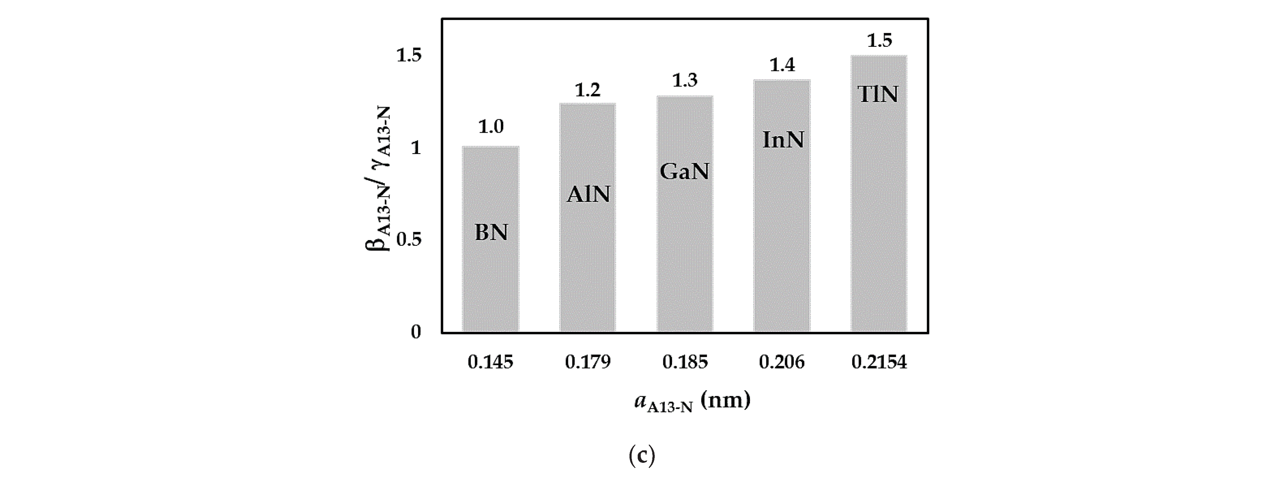
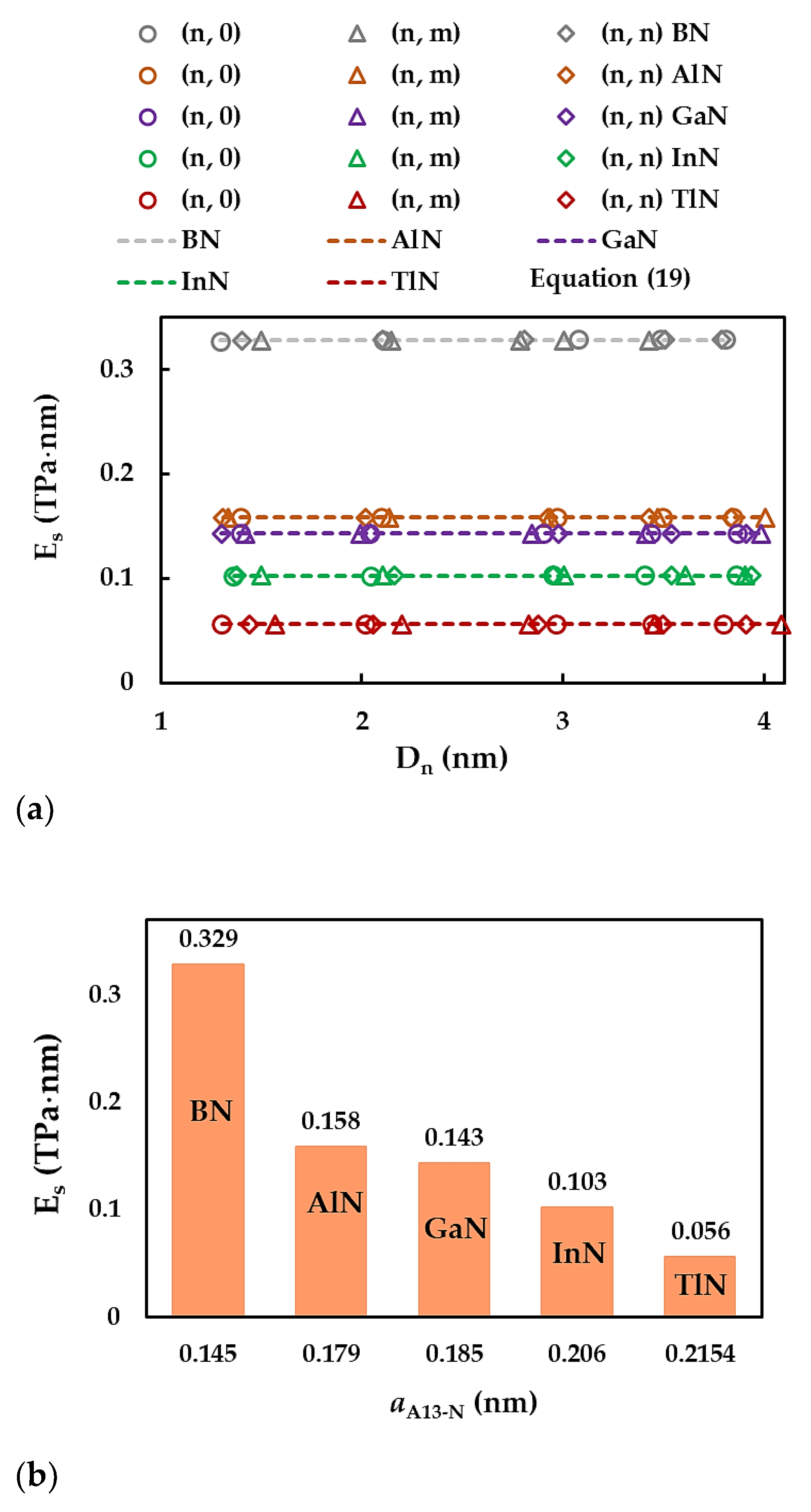
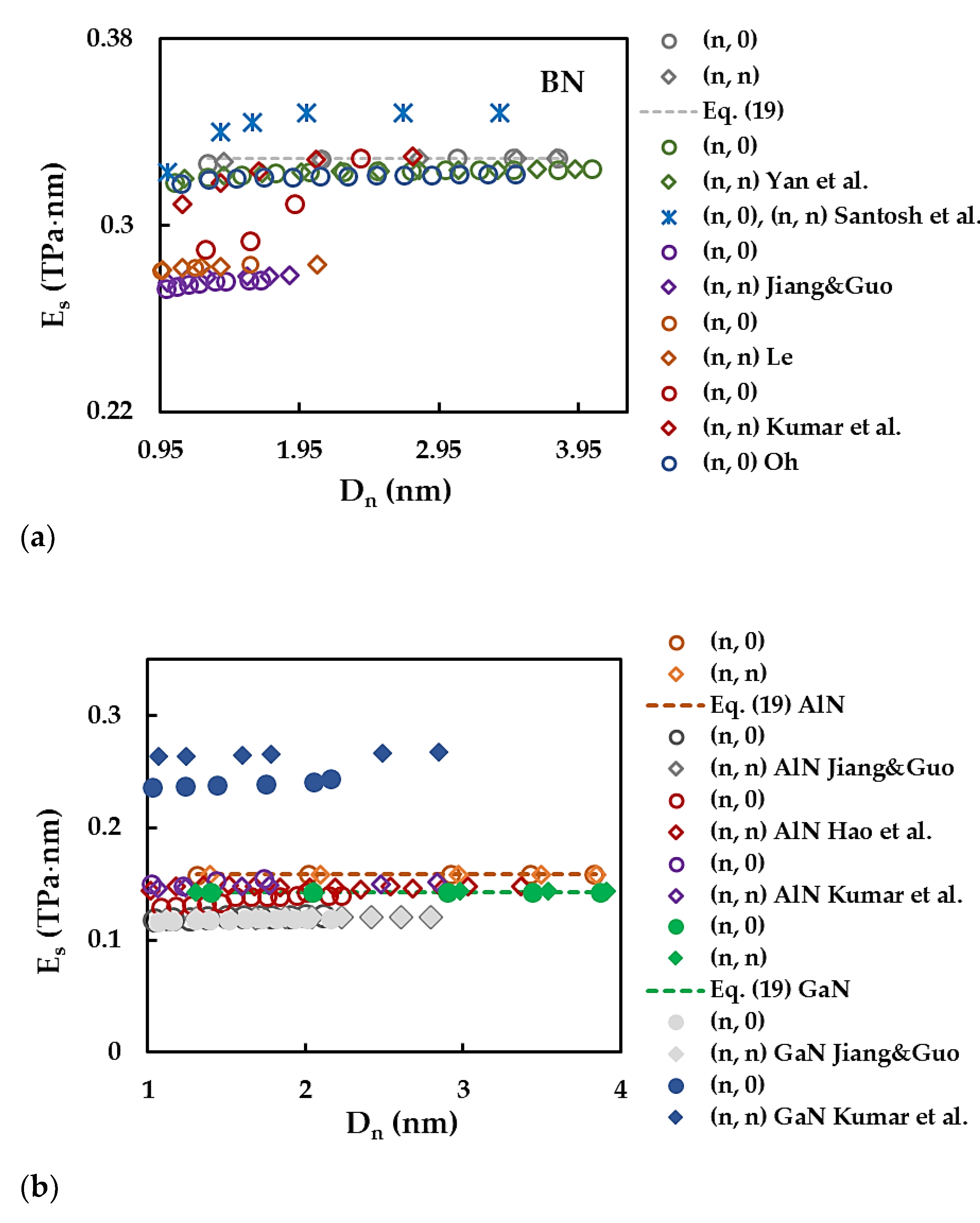
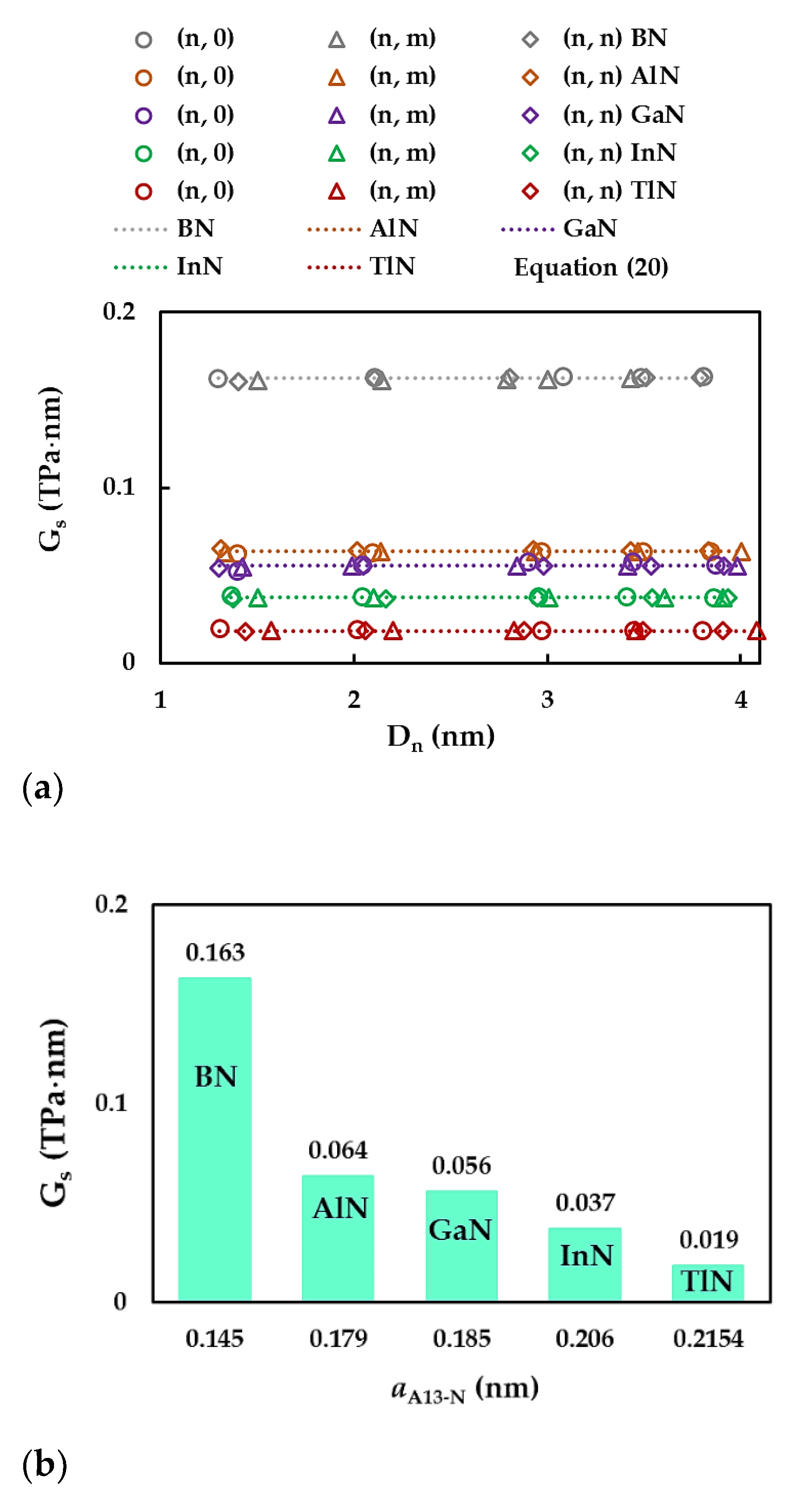
| BN | AlN | GaN | InN | TlN | |
|---|---|---|---|---|---|
| , nm | 0.1446 [53] 0.1447 [66] 0.145 [65] 0.147 [50] 0.151 [67] 0.153 [68] |
0.177 [50] 0.179 [65] 0.1805 [1] 0.185 [69] 0.1856 [53] 0.193 [70] 0.195 [71] |
0.175 [72] 0.184 [50] 0.185 [65] 0.1852 [1] 0.186 [69] 0.1863 [53] 0.194 [70] |
0.203 [44] 0.206 [65] 0.2074 [1] |
0.2154 [1] 0.224 [46] 0.230 [4] |
| NT type | SWBNNTs | SWAlNNTs | SWGaNNTs | SWInNNTs | SWTlNNTs | |||||
|---|---|---|---|---|---|---|---|---|---|---|
| (n, m) | Dn, nm* | (n, m) | Dn, nm* | (n, m) | Dn, nm* | (n, m) | Dn, nm | (n, m) | Dn, nm | |
| zigzag, θ = 0° |
(16, 0) | 1.297 | (13, 0) | 1.312 | (13, 0) | 1.398 | (12, 0) | 1.363 | (11, 0) | 1.306 |
| (26, 0) | 2.107 | (20, 0) | 2.018 | (19, 0) | 2.043 | (18, 0) | 2.044 | (17, 0) | 2.019 | |
| (38, 0) | 3.080 | (29, 0) | 2.926 | (27, 0) | 2.903 | (26, 0) | 2.953 | (25, 0) | 2.969 | |
| (43, 0) | 3.485 | (34, 0) | 3.430 | (32, 0) | 3.440 | (30, 0) | 3.407 | (29, 0) | 3.444 | |
| (47, 0) | 3.809 | (38, 0) | 3.834 | (36, 0) | 3.870 | (34, 0) | 3.862 | (32, 0) | 3.800 | |
| chiral, θ = 19.1° |
(14, 7) | 1.501 | (10, 5) | 1.335 | (10, 5) | 1.422 | (10, 5) | 1.502 | (10, 5) | 1.571 |
| (20, 10) | 2.144 | (16, 8) | 2.136 | (14, 7) | 1.991 | (14, 7) | 2.103 | (14, 7) | 2.199 | |
| (26, 13) | 2.788 | (22, 11) | 2.936 | (20, 10) | 2.844 | (20, 10) | 3.005 | (18, 9) | 2.828 | |
| (28, 14) | 3.002 | (26, 13) | 3.470 | (24, 12) | 3.413 | (24, 12) | 3.606 | (22, 11) | 3.456 | |
| (32, 16) | 3.431 | (30, 15) | 4.004 | (28, 14) | 3.982 | (26, 13) | 3.906 | (26, 13) | 4.085 | |
| armchair, θ = 30° |
(10, 10) | 1.404 | (8, 8) | 1.398 | (7, 7) | 1.303 | (7, 7) | 1.377 | (7, 7) | 1.440 |
| (15, 15) | 2.106 | (12, 12) | 2.097 | (11, 11) | 2.048 | (11, 11) | 2.164 | (10, 10) | 2.057 | |
| (20, 20) | 2.807 | (17, 17) | 2.971 | (16, 16) | 2.979 | (15, 15) | 2.951 | (14, 14) | 2.880 | |
| (25, 25) | 3.509 | (20, 20) | 3.495 | (19, 19) | 3.538 | (18, 18) | 3.541 | (17, 17) | 3.497 | |
| (27, 27) | 3.790 | (22, 22) | 3.845 | (21, 21) | 3.910 | (20, 20) | 3.934 | (19, 19) | 3.908 | |
| Compound | , nm [65] | Es, nN/nm [65] | [65] | , nN/nm | , nN⋅nm/rad2 | , nN⋅nm/rad2 |
|---|---|---|---|---|---|---|
| BN | 0.145 | 267 | 0.21 | 585 | 0.994 | 2.470 |
| AlN | 0.179 | 116 | 0.46 | 372 | 0.451 | 0.625 |
| GaN | 0.185 | 110 | 0.48 | 366 | 0.445 | |
| InN | 0.206 | 67 | 0.59 | 283 | 0.296 | |
| TlN | 0.2154* | 34.5* | 0.689* | 192 | 0.151 |
| Compound | diameter, d, nm |
Formulation | Young´s modulus, Eb, GPa |
Formulation | Shear modulus, Gb, GPa |
Formulation | |
|---|---|---|---|---|---|---|---|
| BN | 0.1648 | 3977 | 4941 | 0.21 [65] | |||
| AlN | 0.1392 | 4374 | 3032 | 0.46 [65] | |||
| GaN | 0.1395 | 4437 | 3113 | 0.48 [65] | |||
| InN | 0.1294 | 4432 | 4674 | 0.59 [65] | |||
| TlN | 0.1120 | 4200 | 8712 | 0.689 [1] |
 |
Disclaimer/Publisher’s Note: The statements, opinions and data contained in all publications are solely those of the individual author(s) and contributor(s) and not of MDPI and/or the editor(s). MDPI and/or the editor(s) disclaim responsibility for any injury to people or property resulting from any ideas, methods, instructions or products referred to in the content. |
© 2024 by the authors. Licensee MDPI, Basel, Switzerland. This article is an open access article distributed under the terms and conditions of the Creative Commons Attribution (CC BY) license (http://creativecommons.org/licenses/by/4.0/).


