Submitted:
08 April 2024
Posted:
09 April 2024
You are already at the latest version
Abstract
Keywords:
1. Introduction
2. Materials and Experimental Methods
2.1. Materials
2.2. Experimental Methods
2.2.1. Organoclays Synthesis
2.2.2. Cyclic Voltammetry Characterization
- -
- The diffusion is the movement of the electro-active species caused by a gradient of concentration created following the reactions of oxidation-reduction of the species at the surface of the electrode;
- -
- The migration is the movement of the species caused by a gradient of the potential applied to the electrode;
- -
- Convection is the movement of the species in solution caused by mechanical forces.
3. Results and Discussion
3.1. Effect of Surfactant Loading on the Cyclic Voltammogram Response of the Carbon Paste Electrode and Carbon Paste Modified Electrodes
3.2. Diagnosis of the Fast, Quasi Fast or Slow Character of the System on the CPE or CPME
3.2.1. Effect of Scanning Rate on the Cyclic Voltammetry Response of Organoclays Modified Carbon Paste Electrode (CPME)
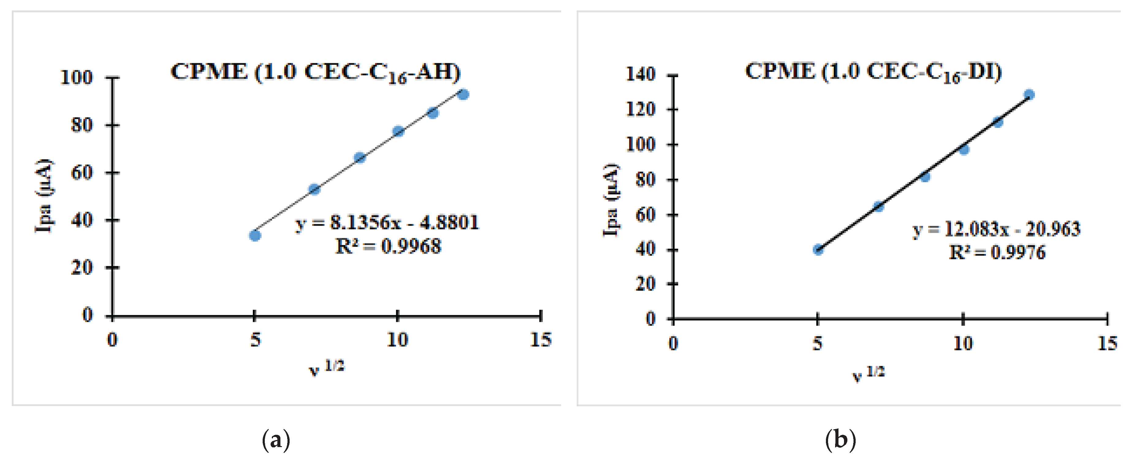
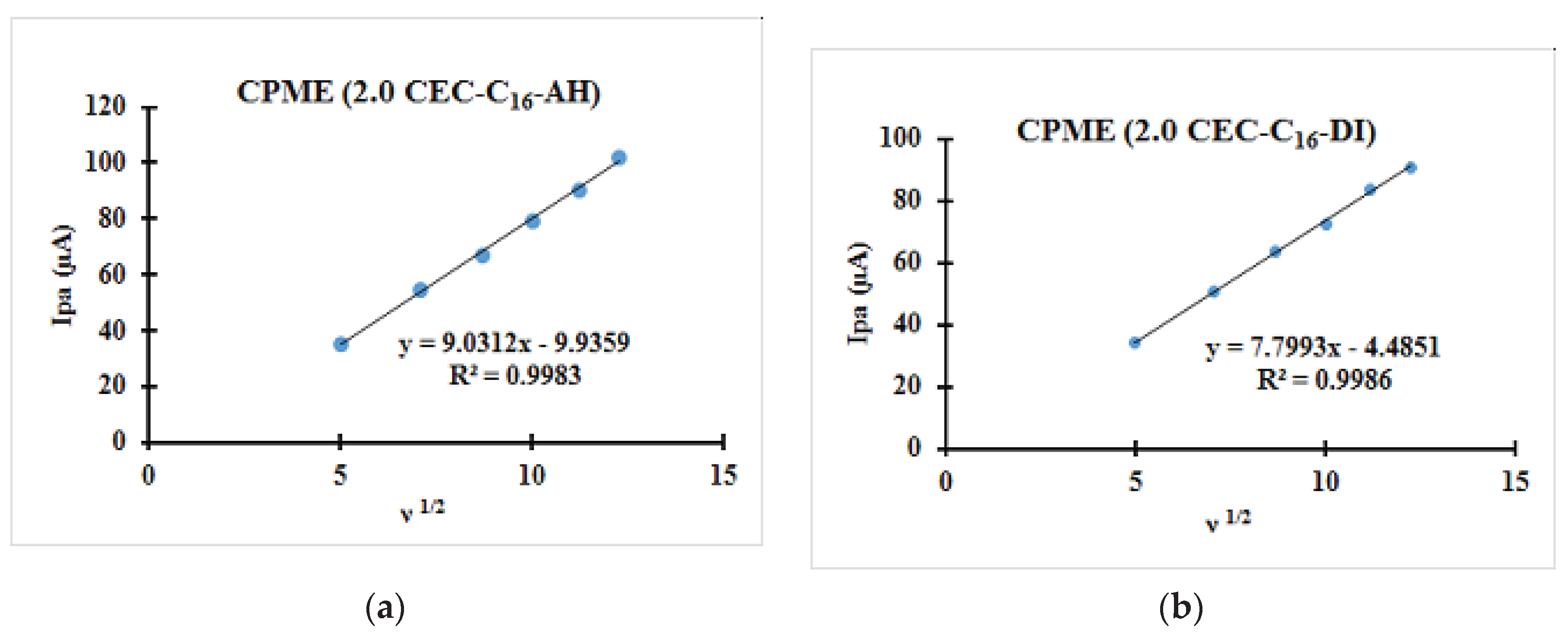
3.2.2. Relationships between the Scanning Rate and the Anodic Peak Intensity
4. Conclusion
Author Contributions
Funding
Acknowledgments
References
- Paiva L. B., Morales A. R., F. R. V. Díaz. Organoclays: Properties, preparation and applications. Appl. Clay Sci. 42, 8–24 (2008).
- Walcarius, A.; Ganesan, V.; Poincare, H.; et al. Ion-Exchange Properties and Electrochemical Characterization of Quaternary Ammonium-Functionalized Silica Microspheres Obtained by the Surfactant Template Route. Langmuir 2006, 22, 469–477. [Google Scholar] [CrossRef] [PubMed]
- Zuzana, N.; Kula, P. Clay Modified Electrodes: Present Applications and Prospects: Review. Electroanalysis 2003, 15, 837–846. [Google Scholar]
- Ngameni, E.; Tonlé, I.K.; Apohkeng, J.T.; Bouwé, R.G.B.; Jieumboué, A.T.; Walcarius, A. Permselective and Preconcentration Properties of a Surfactant-Intercalated Clay Modified Electrode. Electroanalysis 2006, 18, 2243–2250. [Google Scholar] [CrossRef]
- Mojović, Z.; Jović-Jovičić, N.; Banković, P.; Žunić, M.; Rabi-Stanković, A.A.; Milutinović-Nikolić, A.; Jovanović, D. Electrooxidation of phenol on different organo bentonite-based electrodes. Appl. Clay Sci. 2011, 53, 331–335. [Google Scholar] [CrossRef]
- Tonle, I.K.; Ngameni, E.; Walcarius, A. From clay- to organoclay-film modified electrodes : tuning charge selectivity in ion exchange voltammetry. Electrochim. Acta 2004, 49, 3435–3443. [Google Scholar] [CrossRef]
- Tcheumia, H. L.; Tcheumia H., L.; Tonle I., K.; Ngamenia, E.; Walcariusc, A. Electrochemical analysis of methylparathion pesticide by a gemini surfactant-intercalated clay-modified electrode. Talanta 2010, 81, 972–979. [Google Scholar] [CrossRef] [PubMed]
- Tcheumi, H.L.; Tonle, I.K.; Walcarius, A.; Ngameni, E. Electrocatalytic and Sensors Properties of Natural Smectite Type Clay towards the Detection of Paraquat Using a Film-Modified Electrode. Am. J. Anal. Chem. Am. J. Anal. Chem. 2012, 3, 746–754. [Google Scholar] [CrossRef]
- Hu, C.; Dang, X.; Hu, S. Studies on adsorption of cetyltrimethylammonium bromide at carbon paste electrode and the enhancement effect in thyroxine reduction by voltammetry and electrochemical impedance spectroscopy. J. Electroanal. Chem. 2004, 572, 161–171. [Google Scholar] [CrossRef]
- Falaras, P.; Dimitris, P. Incorporation electrodes of anionic species in organoclay-modified. J. Electroanal. Chem. 1992, 331, 229–239. [Google Scholar] [CrossRef]
- Mojović, Z.; Jović-Jovičić, N.; Milutinović-Nikolić, A.; Banković, P.; Rabi-Stanković, A.A.; Jovanović, D. Phenol determination on HDTMA-bentonite-based electrodes. J. Hazard. Mater. 2011, 194, 178–184. [Google Scholar] [CrossRef]
- Cubuk, O.; Caglar, B.; Topcu, C.; Coldur, F.; Sarp, G.; Tabak, A., et al.; et al. Structural characterization of hexadecyltrimethylammonium-smectite composites and their potentiometric electrode applications. Appl. Surf. Sci. 2015, 338, 99–112. [Google Scholar] [CrossRef]
- Navrátilová, Z.; Mucha, M. Organo-montmorillonites as carbon paste electrode modifiers. J Solid State Electrochem. 2015, 19, 2013–2022. [Google Scholar] [CrossRef]
- Hu, C.; Hu, S. Electrochemical characterization of cetyltrimethyl ammonium bromide modified carbon paste electrode and the application in the immobilization of DNA. Electrochimica Acta 2004, 49, 405–412. [Google Scholar] [CrossRef]
- Garikoé, I.; Sorgho, B.; Guel, B.; Persson, I. Solid-state synthesis and physico-chemical characterization of modified smectites using natural clays from Burkina Faso. Bull. Chem. Soc. Ethiop. 2021, 35, 43–59. [Google Scholar] [CrossRef]
- Gariko, I.; Guel, B.; Persson, I. Sorption of Bisphenol A as Model for Sorption Ability of Organoclays. Molecules 2022, 27, 4343. [Google Scholar] [CrossRef] [PubMed]
- Zuzana, N.; Roman, M. Application of Electrochemistry for Studying Sorption Properties of Montmorillonite. Clays Miner. Nat. 2012, 273–294. [Google Scholar]
- Beitollahi, H.; Karimi-maleh, H.; Khabazzadeh, H. Nanomolar and Selective Determination of Epinephrine in the Presence of Norepinephrine Using Carbon Paste Electrode Modified with Carbon Nanotubes and Novel 2-(4-Oxo-3-phenyl-3,4-dihydro- quinazolinyl) – N’ phenyl-hydrazinecarbothioamide. Anal. Chem. 2008, 80, 9848–9851. [Google Scholar] [CrossRef]
- Shahrokhian, S.; Ghalkhani, M. Simultaneous voltammetric detection of ascorbic acid and uric acid at a carbon-paste modified electrode incorporating thionine – nafion ion-pair as an electron mediator. Electrochim. Acta 2006, 51, 2599–2606. [Google Scholar] [CrossRef]
- Pournaghi-Azar, M.H.; Dastangoo, H. Differential pulse anodic stripping voltammetry of copper in dichloromethane: Application to the analysis of human hair. Anal. Chim. Acta 2000, 405, 135–144. [Google Scholar] [CrossRef]
- Raghu, P.; Reddy, T.M.; Reddaiah, K.; Jaidev, L.R.; Narasimha, G. A novel electrochemical biosensor based on horseradish peroxidase immobilized on Ag-nanoparticles/poly(l-arginine) modified carbon paste electrode toward the determination of pyrogallol/hydroquinone. Enzyme Microb. Technl. 2013, 52, 377–385. [Google Scholar] [CrossRef]
- Ali, M.; Derakhshan, A. Boehmite nano particle modified carbon paste electrode for determination of piroxicam. Sensors Actuators, B. Chem. 2014, 201, 378–386. [Google Scholar]
- Ranđelović, M.S.; Momčilović, M.Z.; Nikolić, G.; Ðordević, J.S. Electrocatalitic behaviour of serpentinite modified carbon paste electrode. J. Electroanal. Chem. 2017, 801, 338–344. [Google Scholar] [CrossRef]
- Hotta, Y.; Inukai, K.; Taniguchia, M.; Yamagishi, A. Electrochemical behavior of hexa-ammineruthenium (III) cations in clay-modified electrodes prepared by the Langmuir-Blodgett method. J. Electroanal. Chem. 1997, 429, 107–114. [Google Scholar] [CrossRef]
- Fernandez, L.; Carrero, H. Electrochemical evaluation of ferrocene carboxylic acids confined on surfactant – clay modified glassy carbon electrodes : oxidation of ascorbic acid and uric acid. Electrochim. Acta 2005, 50, 1233–1240. [Google Scholar] [CrossRef]
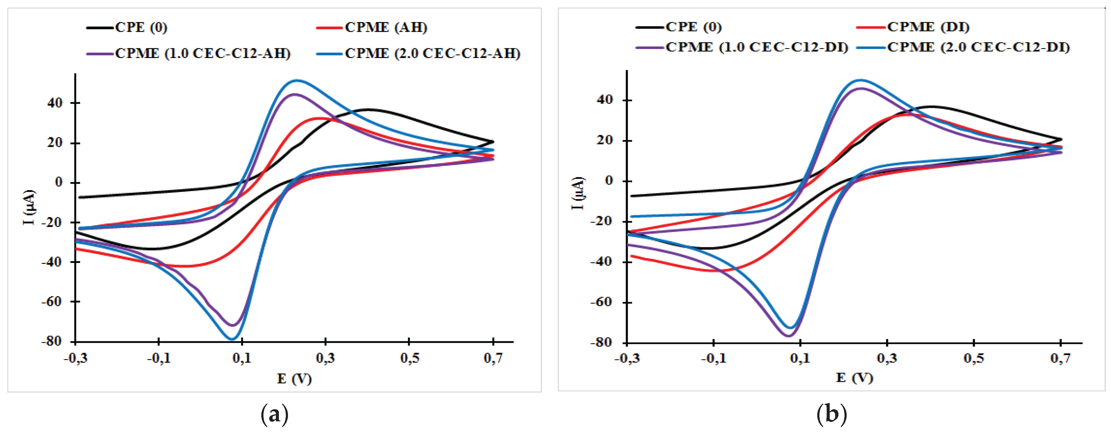
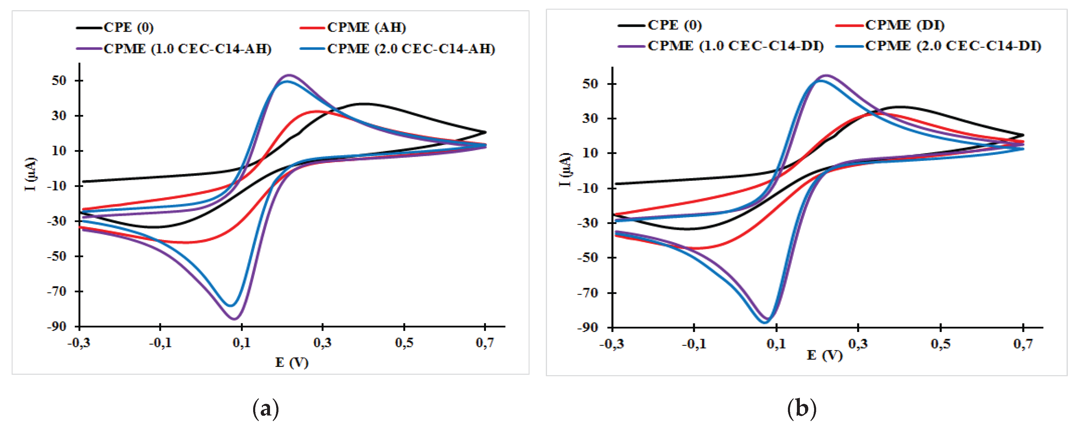
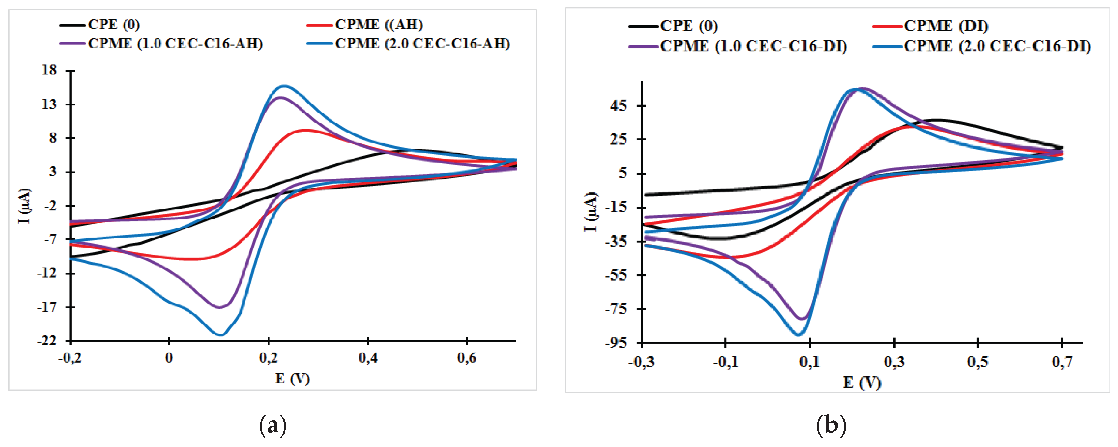
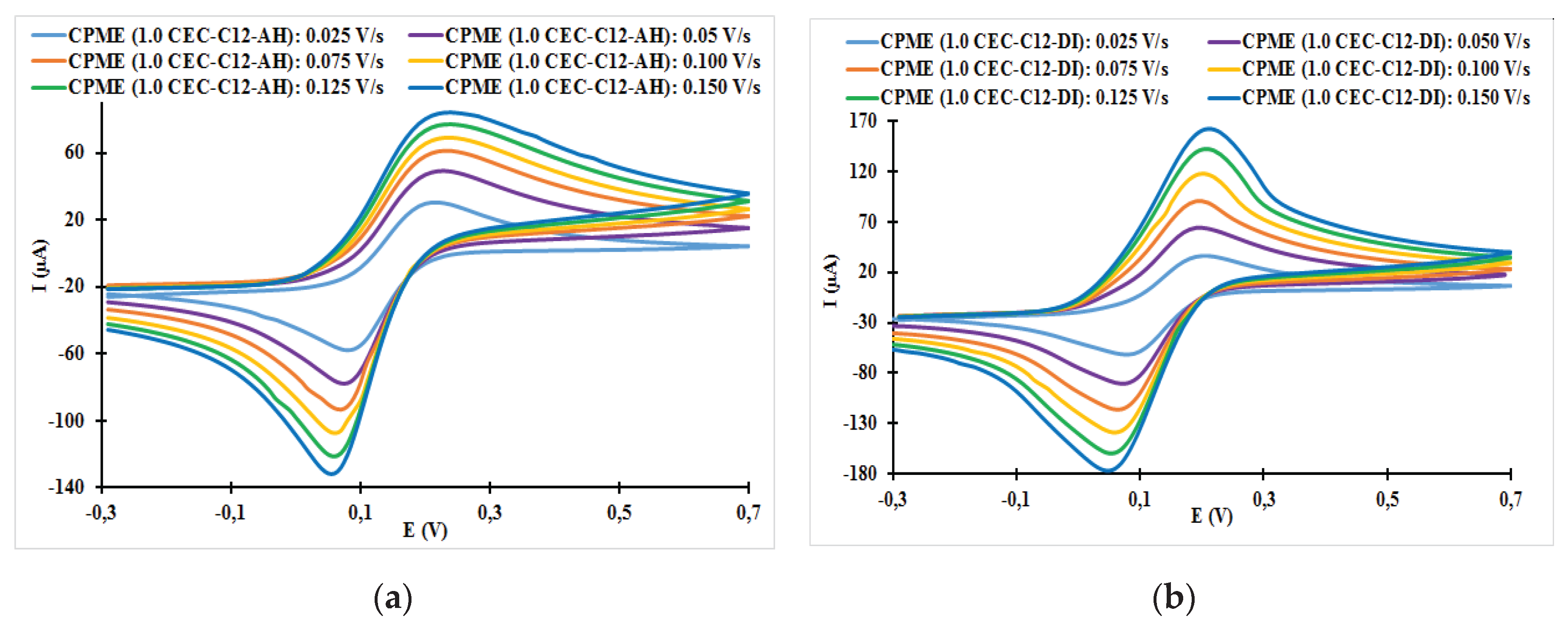

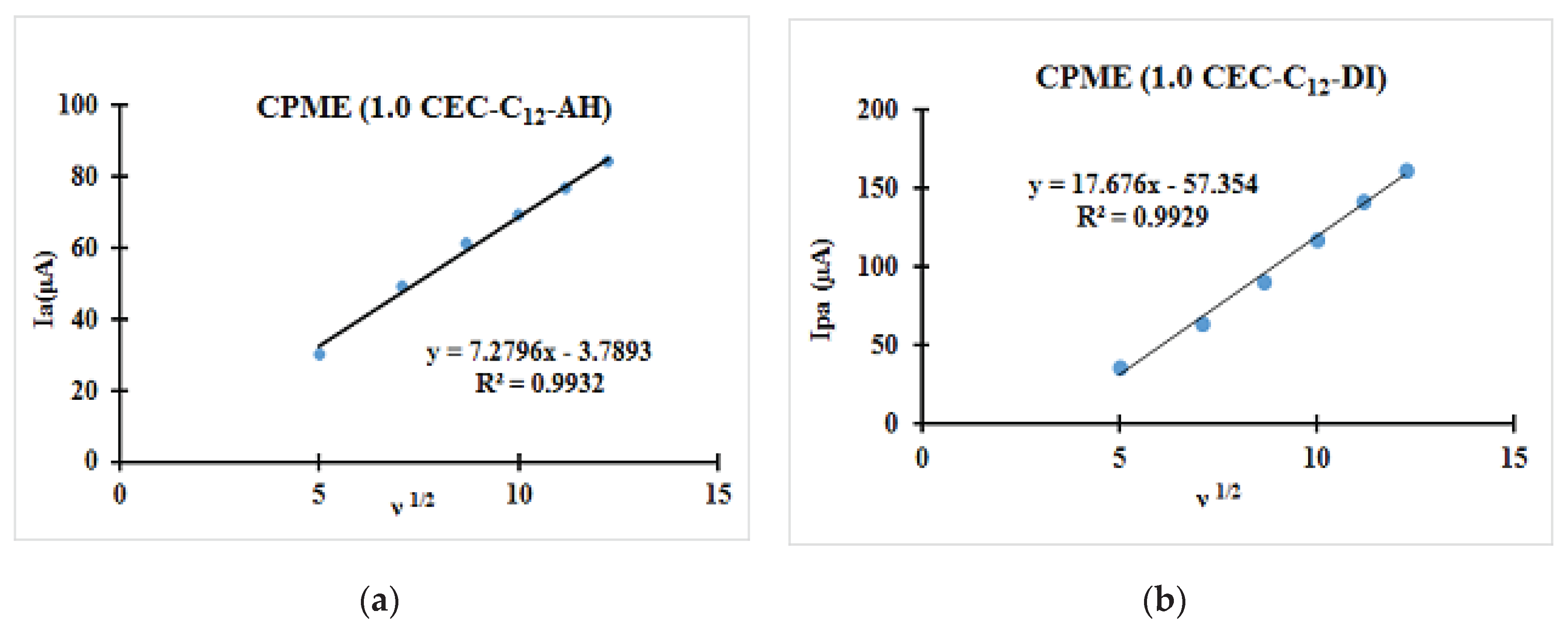
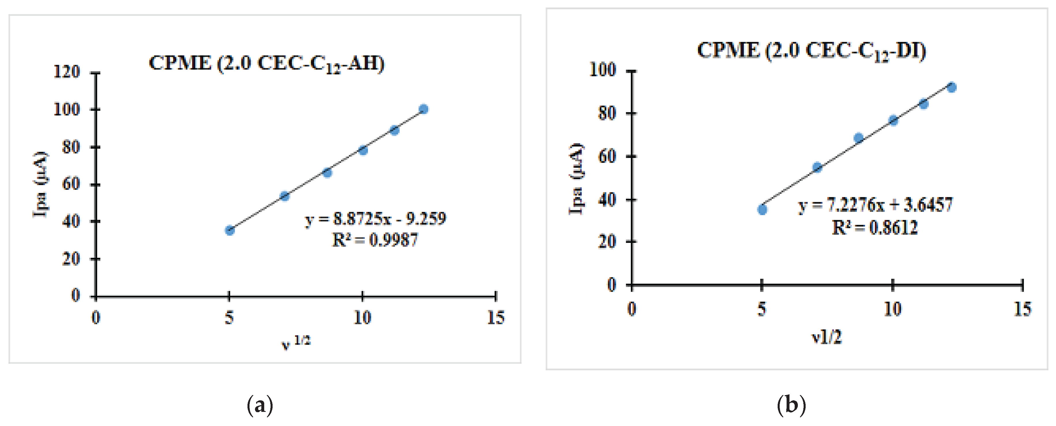
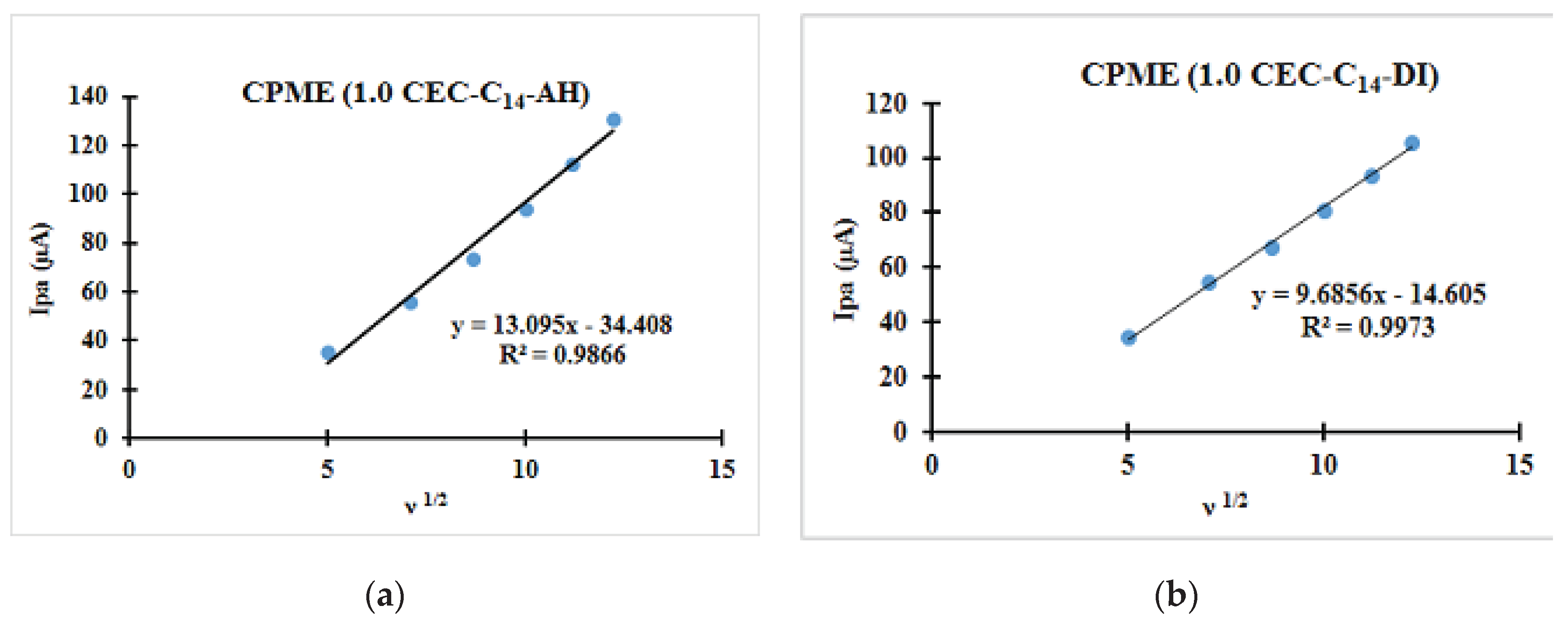
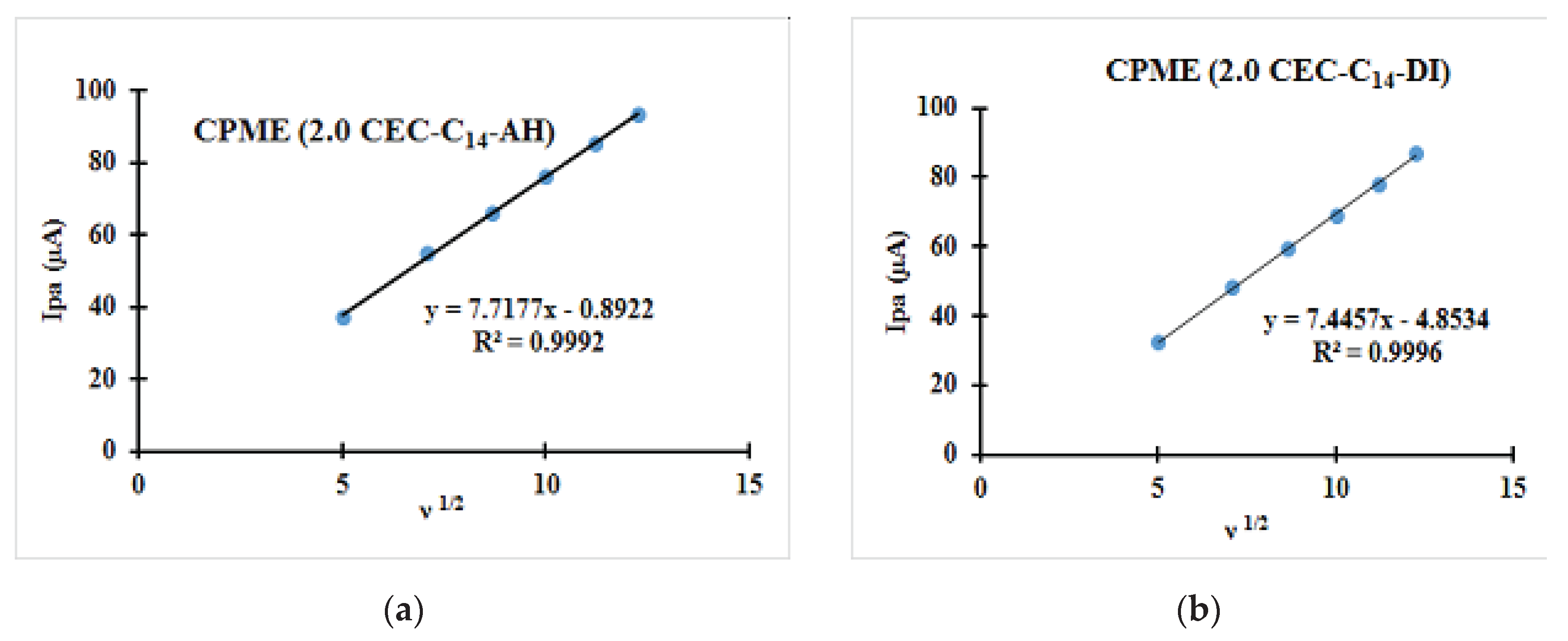
| Fast system (reversible) | Quasi-slow system (quasi reversible) | Very slow system (irreversible) |
|---|---|---|
| ΔEp = Epa−Epc = 59/n (mV at 25 °C) is independent of ν | ΔEp = Epa−Epc is higher than 59/n (mV at 25 °C) and increases with ν | ΔEp = Epa−Epc increases with ν ; Ep-Ep/2 = 47.7/αn |
| Epa and Epc are independent of ν | Epc moves towards the negative values when ν increases | Epa and Epc are related to ν |
| Ipa/Ipc = 1 | Ipa/Ipc = 1 for α = 0,5 | Ipa/Ipc ≠ 1 or not of return |
| Ipa and Ipc vary with ν1/2 | Ip increases with ν, but is not proportional to ν1/2 | Ip varies with ν1/2 |
| Electrodes | Epa (V) | Epc (V) | ΔE (mV) | Ipa (μA) | Ipc (μA) | ǀIpa/Ipcǀ |
|---|---|---|---|---|---|---|
| CPE (0) | 0.29 | −0.04 | 330 | 32.43 | −42.0 | 0.772 |
| CPME (DI) | 0.35 | −0.10 | 520 | 32.86 | −44.34 | 0.741 |
| CPME (AH) | 0.40 | −0.12 | 520 | 36.78 | −33.28 | 1.105 |
| CPME (1.0 CEC-C12-AH) | 0.23 | 0.08 | 150 | 44.37 | −71.63 | 0.620 |
| CPME (2.0 CEC-C12-AH) | 0.23 | 0.07 | 160 | 51.49 | −78.54 | 0.656 |
| CPME (1.0 CEC-C12-DI) | 0.24 | 0.07 | 170 | 53.04 | −85.49 | 0.620 |
| CPME (2.0 CEC-C12-DI) | 0.24 | 0.08 | 160 | 51.49 | −78.53 | 0.656 |
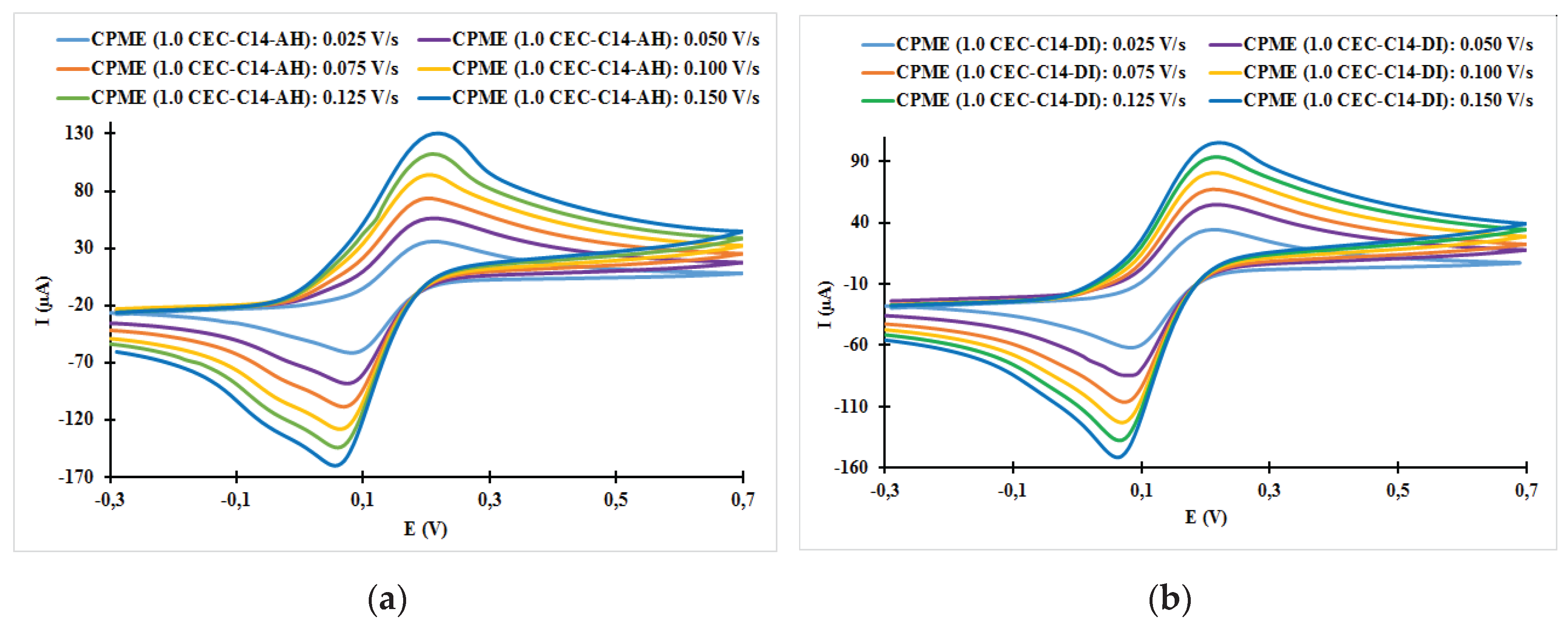
| CPME (1.0 CEC-C14-AH) | 0.22 | 0.08 | 140 | 45.78 | −76.61 | 0.598 |
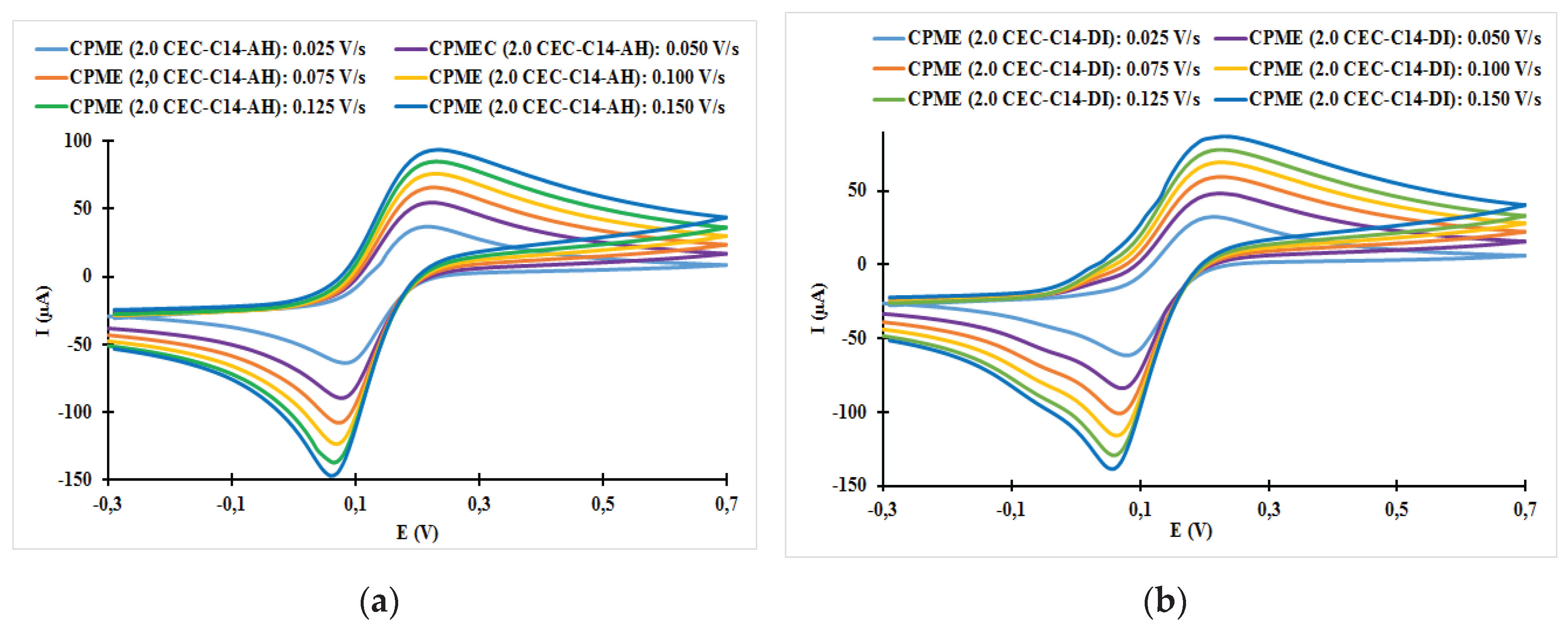
| CPME (2.0 CEC-C14-AH) | 0.21 | 0.07 | 140 | 49.92 | −72.42 | 0.689 |
| CPME (1.0 CEC-C14-DI) | 0.22 | 0.08 | 140 | 53.04 | −85.49 | 0.620 |
| CPME (2.0 CEC-C14-DI) | 0.21 | 0.07 | 140 | 49.45 | −77.98 | 0.634 |
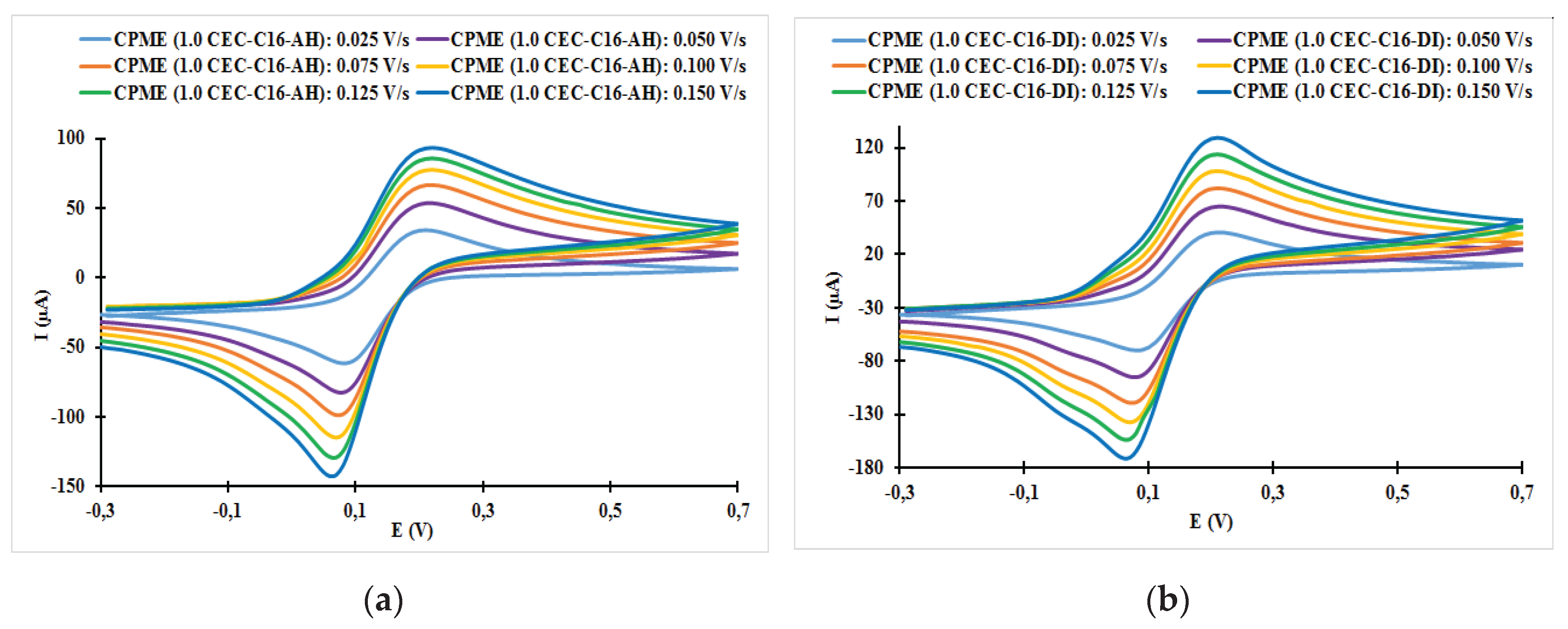
| CPME (1.0 CEC-C16-AH) | 0.22 | 0.08 | 140 | 54.85 | −84.81 | 0.647 |
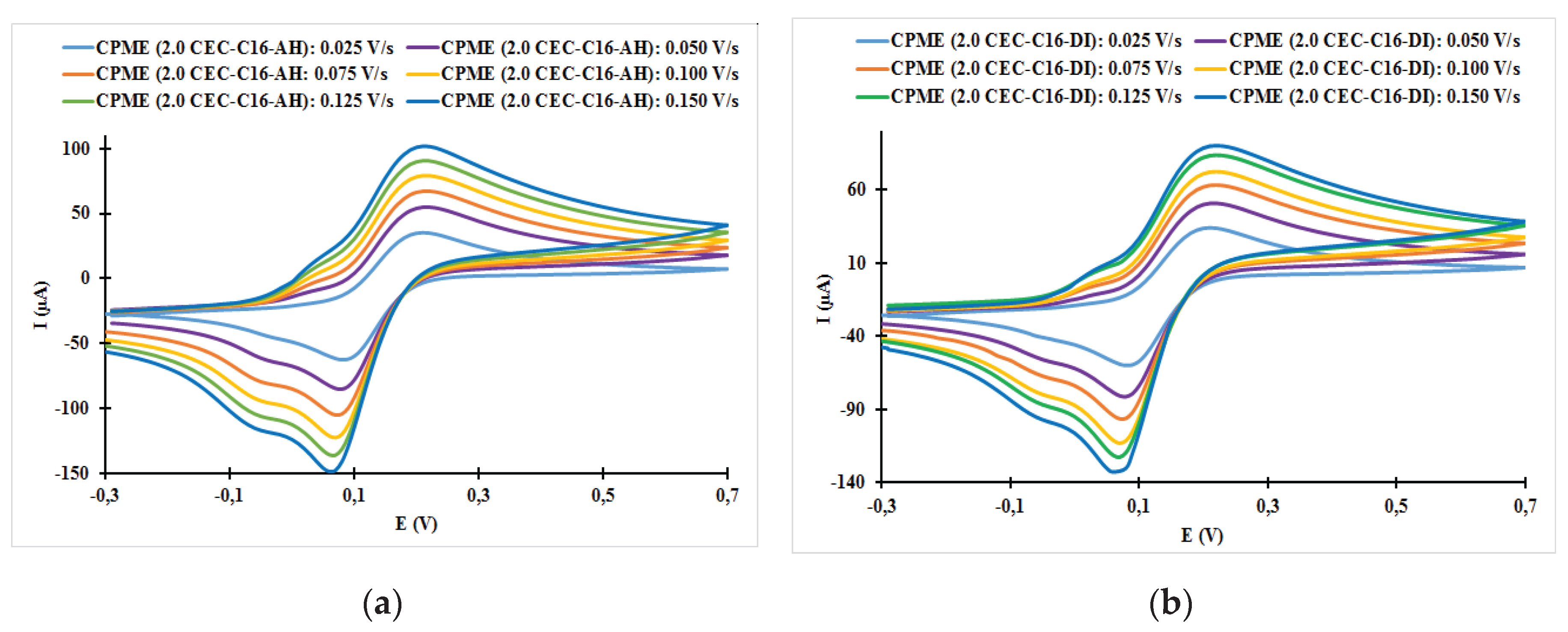
| CPME (2.0 CEC-C16-AH) | 0.21 | 0.07 | 140 | 51.74 | −87.09 | 0.594 |
| CPME (1.0 CEC-C16-DI) | 0.22 | 0.08 | 140 | 53.88 | −89.03 | 0.605 |
| CPME (2.0 CEC-C16-DI) | 0.21 | 0.07 | 140 | 55.41 | −87.02 | 0.637 |
| Electrodes | ν (V/s) | Epa (V) | Epc (V) | ΔE (mV) | ǀIpa/Ipcǀ |
|---|---|---|---|---|---|
| CPME (1.0 CEC-C12-AH) | 0.025 | 0.22 | 0.08 | 140 | 0.82 |
| CPME (1.0 CEC-C12-AH) | 0.050 | 0.23 | 0.08 | 150 | 0.74 |
| CPME (1.0 CEC-C12-AH) | 0.075 | 0.23 | 0.07 | 160 | 0.67 |
| CPME (1.0 CEC-C12-AH) | 0.100 | 0.24 | 0.06 | 180 | 0.64 |
| CPME (1.0 CEC-C12-AH) | 0.125 | 0.24 | 0.06 | 180 | 0.65 |
| CPME (1.0 CEC-C12-AH) | 0.150 | 0.24 | 0.06 | 180 | 0.65 |
| CPME (1.0 CEC-C12-DI) | 0.025 | 0.20 | 0.08 | 120 | 0.92 |
| CPME (1.0 CEC-C12- DI) | 0.050 | 0.20 | 0.07 | 130 | 0.89 |
| CPME (1.0 CEC-C12- DI) | 0.075 | 0.20 | 0.06 | 140 | 0.85 |
| CPME (1.0 CEC-C12- DI) | 0.100 | 0.20 | 0.06 | 140 | 0.78 |
| CPME (1.0 CEC-C12- DI) | 0.125 | 0.21 | 0.05 | 150 | 0.71 |
| CPME (1.0 CEC-C12- DI) | 0.150 | 0.21 | 0.05 | 150 | 0.59 |
| CPME (2.0 CEC-C12- AH) | 0.025 | 0.21 | 0.07 | 140 | 0.60 |
| CPME (2.0 CEC-C12- AH) | 0.050 | 0.21 | 0.07 | 140 | 0.64 |
| CPME (2.0 CEC-C12- AH) | 0.075 | 0.21 | 0.06 | 150 | 0.64 |
| CPME (2.0 CEC-C12- AH) | 0.100 | 0.21 | 0.05 | 160 | 0.65 |
| CPME (2.0 CEC-C12- AH) | 0.125 | 0.20 | 0.05 | 160 | 0.66 |
| CPME (2.0 CEC-C12- AH) | 0.150 | 0.21 | 0.04 | 170 | 0.69 |
| CPME (2.0 CEC-C12-DI) | 0.025 | 0.21 | 0.08 | 130 | 0.90 |
| CPME (2.0 CEC-C12-DI) | 0.050 | 0.23 | 0.07 | 160 | 0.81 |
| CPME (2.0 CEC-C12-DI) | 0.075 | 0.22 | 0.07 | 150 | 0.73 |
| CPME (2.0 CEC-C12-DI) | 0.100 | 0.23 | 0.06 | 170 | 0.71 |
| CPME (2.0 CEC-C12-DI) | 0.125 | 0.24 | 0.06 | 180 | 0.68 |
| CPME (2.0 CEC-C12-DI) | 0.150 | 0.24 | 0.06 | 180 | 0.64 |
| CPME (1.0 CEC-C14-AH) | 0.025 | 0.21 | 0.08 | 130 | 0.58 |
| CPME (1.0 CEC-C14-AH) | 0.050 | 0.21 | 0.07 | 140 | 0.64 |
| CPME (1.0 CEC-C14-AH) | 0.075 | 0.20 | 0.07 | 130 | 0.68 |
| CPME (1.0 CEC-C14-AH) | 0.100 | 0.20 | 0.06 | 140 | 0.73 |
| CPME (1.0 CEC-C14-AH) | 0.125 | 0.22 | 0.06 | 160 | 0.77 |
| CPME (1.0 CEC-C14-AH) | 0.150 | 0.22 | 0.06 | 160 | 0.82 |
| CPME (1.0 CEC-C14-DI) | 0.025 | 0.21 | 0.08 | 130 | 0.56 |
| CPME (1.0 CEC-C14- DI) | 0.050 | 0.22 | 0.07 | 150 | 0.65 |
| CPME (1.0 CEC-C14- DI) | 0.075 | 0.21 | 0.07 | 140 | 0.63 |
| CPME (1.0 CEC-C14- DI) | 0.100 | 0.21 | 0.07 | 140 | 0.66 |
| CPME (1.0 CEC-C14- DI) | 0.125 | 0.22 | 0.07 | 130 | 0.68 |
| CPME (1.0 CEC-C14- DI) | 0.150 | 0.22 | 0.06 | 160 | 0.70 |
| CPME (2.0 CEC-C14-AH) | 0.025 | 0.21 | 0.08 | 130 | 0.58 |
| CPME (2.0 CEC-C14-AH) | 0.050 | 0.22 | 0.08 | 140 | 0.61 |
| CPME (2.0 CEC-C14-AH) | 0.075 | 0.23 | 0.07 | 160 | 0.62 |
| CPME (2.0 CEC-C14-AH) | 0.100 | 0.23 | 0.07 | 160 | 0.62 |
| CPME (2.0 CEC-C14-AH) | 0.125 | 0.23 | 0.07 | 160 | 0.62 |
| CPME (2.0 CEC-C14-AH) | 0.150 | 0.23 | 0.06 | 170 | 0.64 |
| CPME (2.0 CEC-C14-DI) | 0.025 | 0.21 | 0.08 | 130 | 0.52 |
| CPME (2.0 CEC-C14-DI) | 0.050 | 0.22 | 0.07 | 150 | 0.57 |
| CPME (2.0 CEC-C14-DI) | 0.075 | 0.23 | 0.06 | 170 | 0.59 |
| CPME (2.0 CEC-C14-DI) | 0.100 | 0.23 | 0.06 | 170 | 0.60 |
| CPME (2.0 CEC-C14-DI) | 0.125 | 0.23 | 0.06 | 170 | 0.60 |
| CPME (2.0 CEC-C14-DI) | 0.150 | 0.23 | 0.06 | 170 | 0.70 |
| CPME (1.0 CEC-C16-AH) | 0.025 | 0.21 | 0.08 | 130 | 0.56 |
| CPME (1.0 CEC-C16-AH) | 0.050 | 0.22 | 0.08 | 140 | 0.65 |
| CPME (1.0 CEC-C16-AH) | 0.075 | 0.22 | 0.07 | 150 | 0.68 |
| CPME (1.0 CEC-C16-AH) | 0.100 | 0.22 | 0.07 | 150 | 0.68 |
| CPME (1.0 CEC-C16-AH) | 0.125 | 0.22 | 0.07 | 150 | 0.67 |
| CPME (1.0 CEC-C16-AH) | 0.150 | 0.22 | 0.06 | 160 | 0.66 |
| CPME (1.0 CEC-C16-DI) | 0.025 | 0.21 | 0.08 | 130 | 0.58 |
| CPME (1.0 CEC-C16-DI) | 0.050 | 0.21 | 0.08 | 130 | 0.68 |
| CPME (1.0 CEC-C16-DI) | 0.075 | 0.21 | 0.07 | 140 | 0.69 |
| CPME (1.0 CEC-C16-DI) | 0.100 | 0.21 | 0.07 | 140 | 0.71 |
| CPME (1.0 CEC-C16-DI) | 0.125 | 0.21 | 0.06 | 150 | 0.74 |
| CPME (1.0 CEC-C16-DI) | 0.150 | 0.21 | 0.06 | 150 | 0.76 |
| CPME (2.0 CEC-C16-AH) | 0.025 | 0.21 | 0.08 | 130 | 057 |
| CPME (2.0 CEC-C16-AH) | 0.050 | 0.22 | 0.08 | 120 | 0.65 |
| CPME (2.0 CEC-C16-AH) | 0.075 | 0.22 | 0.07 | 150 | 0.64 |
| CPME (2.0 CEC-C16-AH) | 0.100 | 0.22 | 0.07 | 150 | 0.65 |
| CPME (2.0 CEC-C16-AH) | 0.125 | 0.21 | 0.07 | 140 | 0.67 |
| CPME (2.0 CEC-C16-AH) | 0.150 | 0.21 | 0.06 | 150 | 0.69 |
| CPME (2.0 CEC-C16-DI) | 0.025 | 0.21 | 0.08 | 130 | 0.57 |
| CPME (2.0 CEC-C16-DI) | 0.050 | 0.22 | 0.08 | 140 | 0.63 |
| CPME (2.0 CEC-C16-DI) | 0.075 | 0.22 | 0.07 | 150 | 0.66 |
| CPME (2.0 CEC-C16-DI) | 0.100 | 0.22 | 0.07 | 150 | 0.64 |
| CPME (2.0 CEC-C16-DI) | 0.125 | 0.22 | 0.07 | 150 | 0.68 |
| CPME (2.0 CEC-C16-DI) | 0.150 | 0.22 | 0.06 | 160 | 0.68 |
Disclaimer/Publisher’s Note: The statements, opinions and data contained in all publications are solely those of the individual author(s) and contributor(s) and not of MDPI and/or the editor(s). MDPI and/or the editor(s) disclaim responsibility for any injury to people or property resulting from any ideas, methods, instructions or products referred to in the content. |
© 2024 by the authors. Licensee MDPI, Basel, Switzerland. This article is an open access article distributed under the terms and conditions of the Creative Commons Attribution (CC BY) license (http://creativecommons.org/licenses/by/4.0/).


