1. Introduction
The burgeoning expansion of the Internet of Things (IoT) and artificial intelligence (AI) technologies is exerting considerable pressure on the power supply systems of distributed electronic devices [
1,
2]. To mitigate environmental pollution and high expenses associated with frequent battery replacements or routine recharging [
3,
4,
5], it is imperative to address the challenges posed by unsustainable power sources. Mechanical energy harvesting emerges as a pivotal solution for achieving sustainable power supply [
6]. Among various energy harvesting mechanisms, TENGs have garnered significant attention due to their versatile structural designs [
7], straightforward manufacturing processes [
8], low production costs [
9], and the broad spectrum of materials that can be utilized [
10].
TENGs, leveraging the synergistic effects of triboelectrification and electrostatic induction, represent a novel class of electronic devices capable of harvesting mechanical energies such as human motion, tire rotation, wind, tidal forces, vibrations, and ultrasonic waves [
11,
12,
13,
14,
15,
16,
17,
18,
19]. These energies can be efficiently transformed into electricity or electrical signals [
20], showcasing wide-ranging applications in sustainable energy and autonomous sensing domains [
21]. Since Zhonglin Wang’s inaugural report on TENGs in 2012 [
22], this technology has garnered significant interest within the nano-energy sector. Research efforts have encompassed the development of composite friction materials [
23,
24,
25], surface modification of these materials [
26,
27,
28], and innovative structural designs [
29,
30]. While augmenting TENG’s output performance remains a key research objective, minimizing fabrication costs is equally crucial.
In this study, we introduce a FS-TENG, which boasts a straightforward design, low production costs, and ease of fabrication. The FS-TENG is adept at converting low-frequency mechanical energy into electrical power, capable of illuminating several LEDs. Moreover, this FS-TENG can generate varying electrical signals in response to changes in the mechanical energy harvested. Utilizing this characteristic, the FS-TENG is effectively deployed as a self-powered sensor for monitoring mechanical movements.
2. Materials and Methods
2.1. Materials
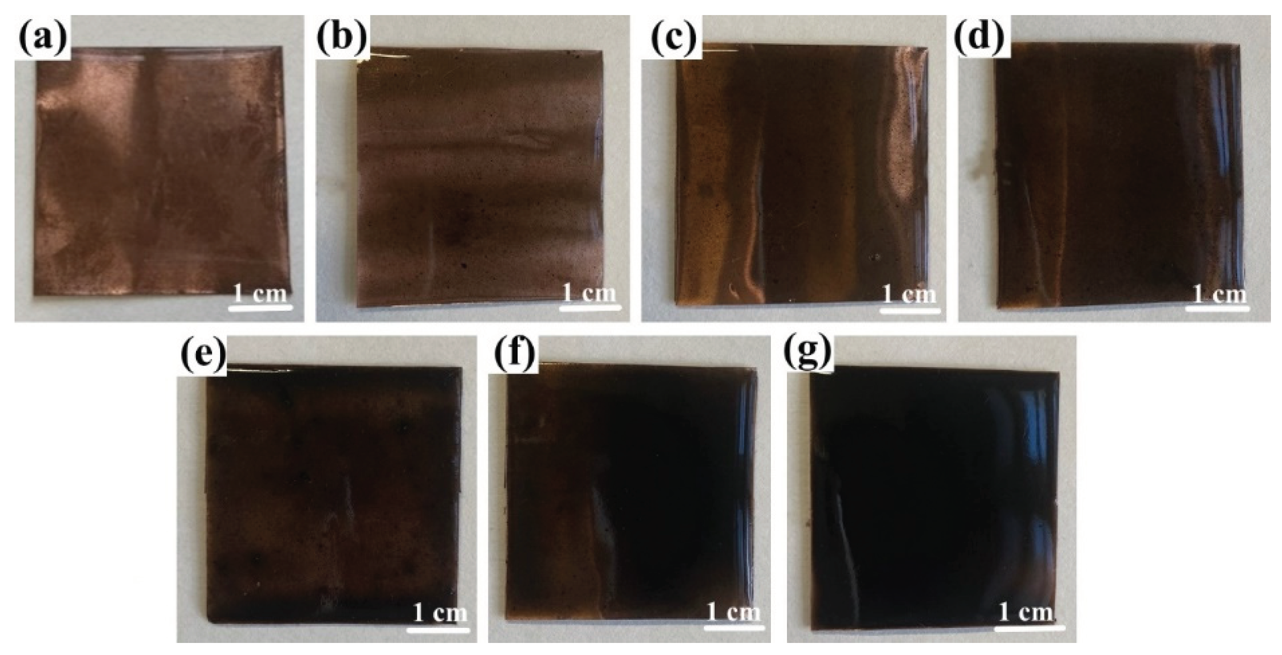
In the construction of the FS-TENG, Polytetrafluoroethylene (PTFE) was selected as a friction material, measuring 150 µm in thickness and 4 cm x 4 cm in size. A 100 nm layer of silver was deposited on one side of the PTFE via magnetron sputtering to serve as an electrode, while the opposite side functioned as the triboelectric layer. For the counter electrode, a copper foil, matching the dimensions of the PTFE and 100 µm thick, was utilized. This foil was coated on one side with a PDMS composite film, incorporating FS, using the spin-coating technique. The resultant PDMS+FS film samples are depicted in
Figure 1.
2.2. Fabrication of FS-TENG
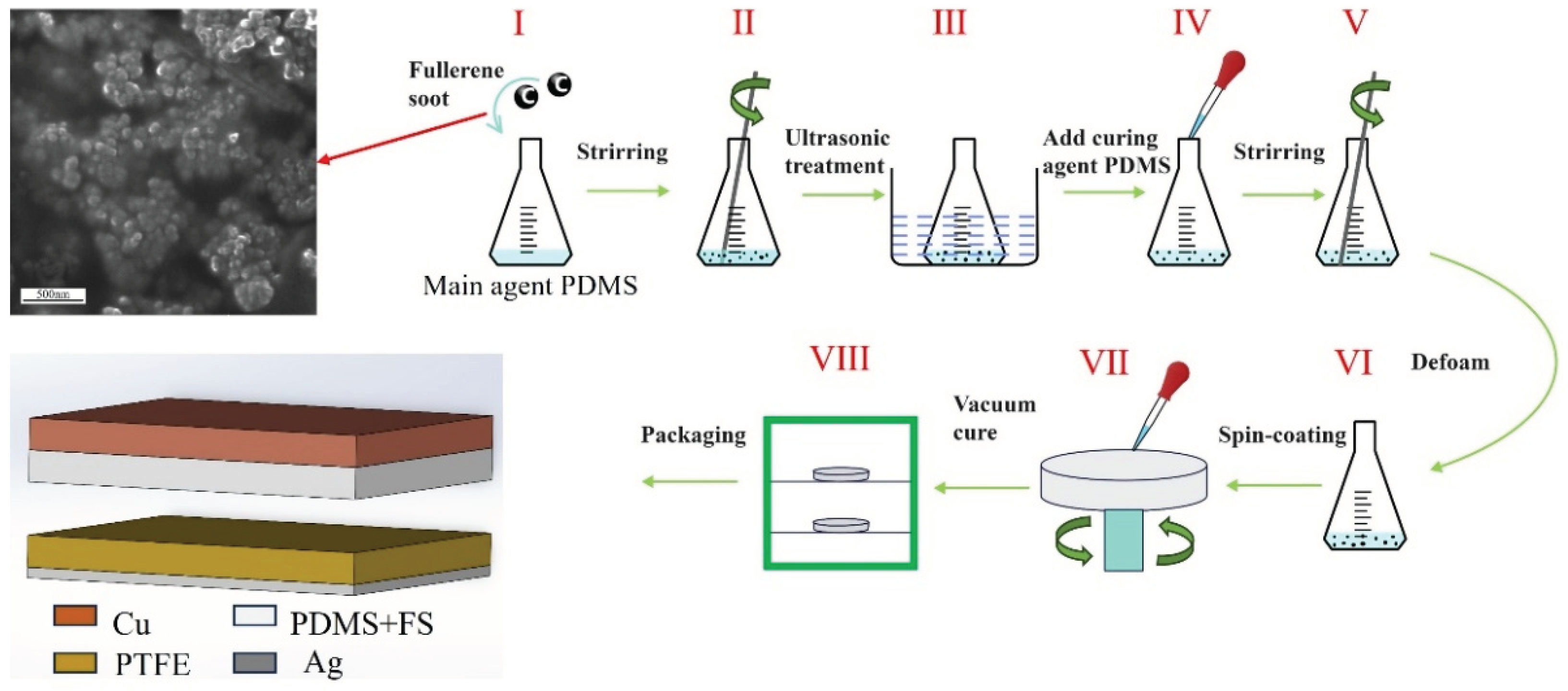
The preparation of the FS-doped PDMS composite films is illustrated in
Figure 2: Initially, the PDMS base and curing agents were measured in a mass ratio of 10:1. Subsequently, various mass fractions of FS — 0.05%, 0.1%, 0.15%, 0.2%, 0.25%, and 0.3% — were individually added to the PDMS base. Following mechanical mixing, the FS-doped PDMS mixture underwent ultrasonic treatment for 1 hour to ensure the homogeneous dispersion of FS within the PDMS base. The curing agent was then introduced to the mixture, which was allowed to degas for 30 minutes. Afterwards, 1.5 ml of the mixture was applied to one side of a copper foil via spin-coating. The coated copper foil was subsequently removed and placed in a vacuum drying oven at 80°C for 4 hours.
The FS-TENG utilizes two composite laminates as substrates, incorporating a pair of sponges between the plates as elastomers to facilitate elastic contact and separation of its electrodes. Initially, the triboelectric layers are positioned 3 mm apart. A schematic of the TENG model is depicted in
Figure 2. A custom-designed, mechanically rational vibrating device, fabricated using a 3D printer, ensures periodic contact and separation between the upper and lower electrodes. The microstructure of the FS nanoparticles was examined using scanning electron microscopy. The electrical output, including current and voltage generated by the TENG, was quantified with a multifunctional electrometer (UNI-T UT8000).
3. Results
3.1. Output Characteristics of FS-TENG
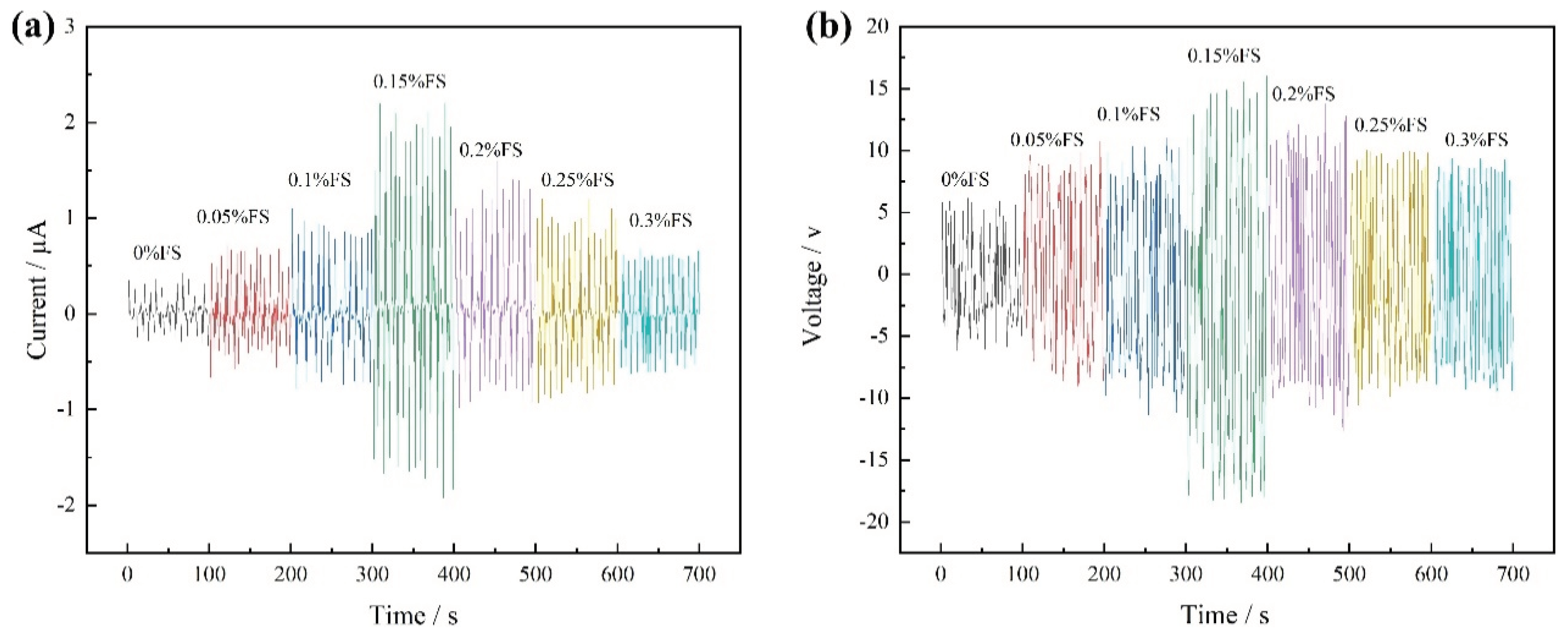
Upon applying a 2 N pressure at a frequency of 3 Hz to the FS-TENG using the vibration device, the Isc and Voc are illustrated in
Figure 3. It is observed that the Isc value progressively increases with the addition of FS, achieving a maximum instantaneous peak of 2.2 µA at an FS concentration of 0.15%. Beyond this point, the peak value of Isc gradually declines with further increases in FS concentration, as depicted in
Figure 3a. Similarly,
Figure 3b shows that Voc follows the same trend as Isc, with the maximum instantaneous peak reaching 18.49 V at the same FS concentration of 0.15%.
The quantity of charge transferred between electrodes in a single power generation cycle of the TENG can be determined by integrating the Isc over time.
Figure 3c illustrates the maximum charge transferred in a single TENG cycle across various mass fractions of FS. Initially, the charge transferred between the electrodes increases with the FS mass fraction, reaching a peak, and subsequently decreases as the FS mass fraction continues to rise. The optimum transferred charge of 1.18 nC is achieved at an FS mass fraction of 0.15%.
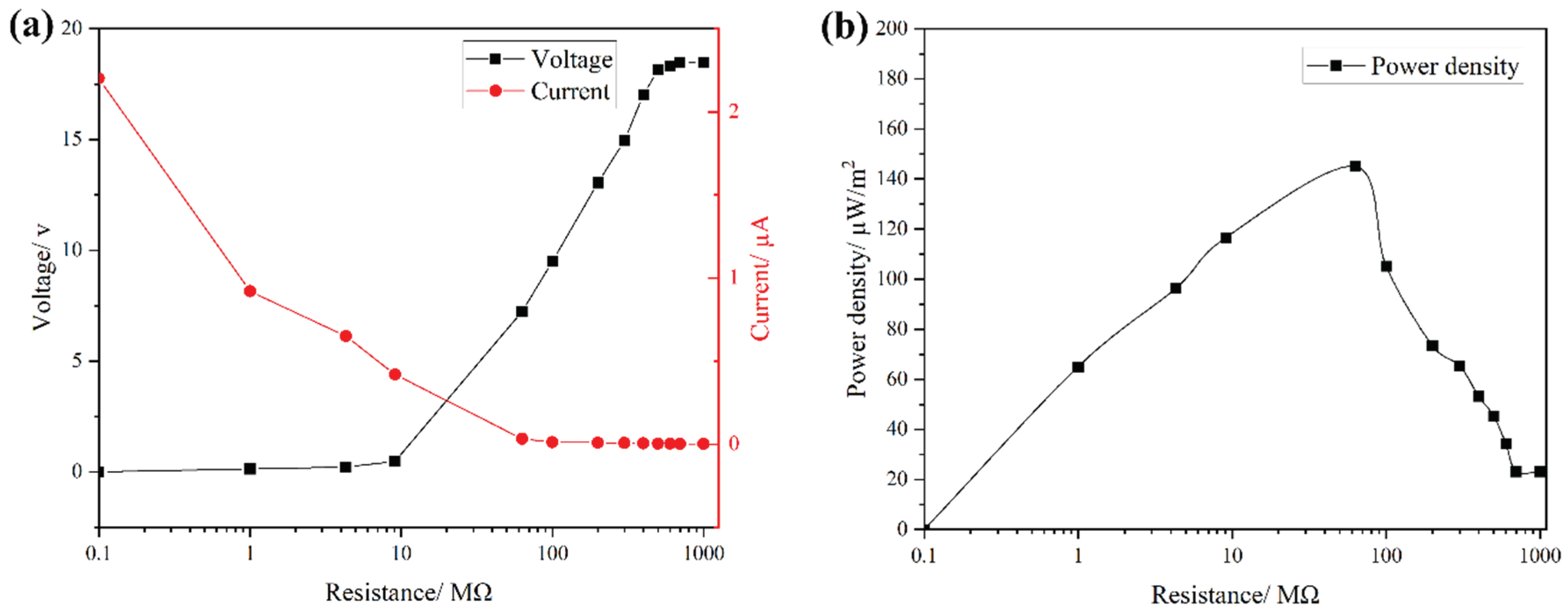
To evaluate the output power density of the FS-TENG, resistors were integrated into the external circuit, and the relationship between current and voltage across the circuit is depicted in
Figure 4a. With the increment of load resistance in the circuit, there is a significant increase in the voltage across the load, accompanied by a rapid decrease in current. The output power density attains its peak at 145 µW/m² when the external circuit is connected to a load resistance of 63 MΩ, as shown in
Figure 4b.
3.2. Working Principle of FS-TENG
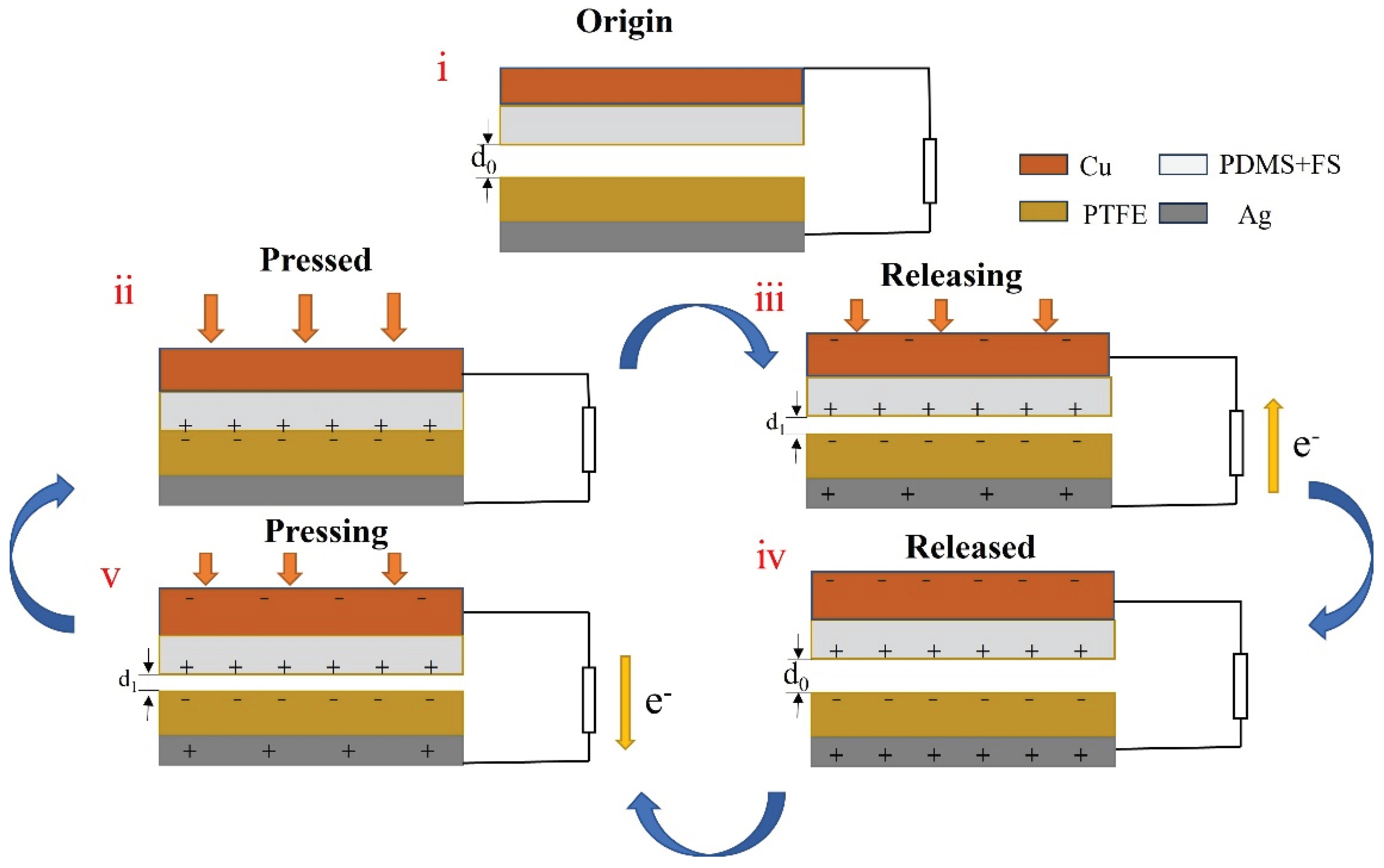
The operating principle of the FS-TENG is outlined as follows: Initially, the triboelectric layers and electrodes are at charge equilibrium, depicted in
Figure 5(i). Upon contact under an external force, the triboelectrification effect results in the generation of positive charges on the PDMS contact surface and negative charges on the PTFE contact surface, as illustrated in
Figure 5(ii). As the triboelectric layers separate, illustrated in
Figure 5(iii), electrostatic induction causes a potential difference between the electrodes. This induces a charge transfer through the external circuit, generating a positive voltage until the potential difference reaches its peak. When the PDMS and PTFE layers reestablish contact, an opposite potential difference is created, and charges move in the reverse direction, leading to a negative voltage, as shown in
Figure 5(v). This cyclical process of contact and separation produces an alternating current in the external circuit.
3.3. Simulation with COMSOL
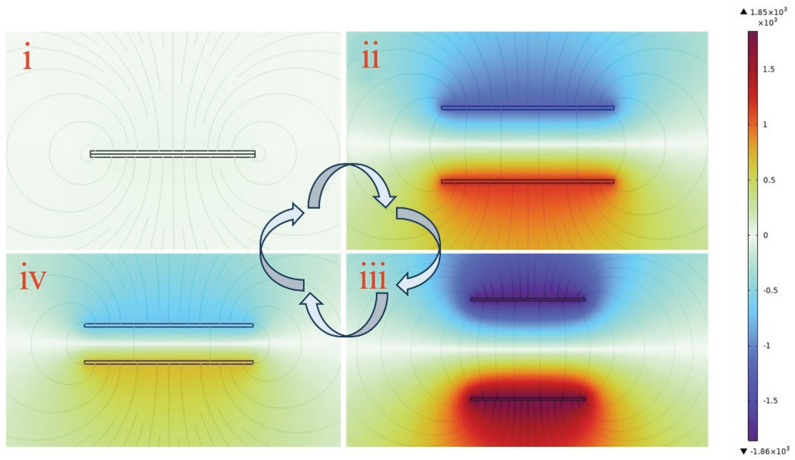
COMSOL software was utilized to simulate the operational mechanism of the FS-TENG, with findings presented in
Figure 6. When the triboelectric layers are in complete contact, as depicted in
Figure 6(i), there is no potential difference between the electrodes. As the triboelectric layers begin to separate, the potential difference between the electrodes gradually escalates. This potential difference reaches its maximum when the layers are separated back to their initial state, indicating that the potential difference augments with the separation of the triboelectric layers, as illustrated in
Figure 6(ii) and (iii). In contrast,
Figure 6(iv) shows that the potential difference between the electrodes decreases when the triboelectric layers approach one another again, similar to the process depicted in
Figure 5(v).
3.4. FS-TENG Powers Microelectronic Devices
A FS-TENG utilizing 0.15% FS was selected for experimentation. To convert the alternating current (AC) produced by the FS-TENG into direct current (DC), a rectifier bridge was incorporated into the circuit. Additionally, a 10 µF capacitor was employed to store the generated electricity. The circuit diagram depicting the operation of the TENG is presented in
Figure 7a. Upon applying mechanical pressure to the FS-TENG for 1350 seconds, the capacitor charged up to 3 V, sufficient to instantaneously illuminate 72 LEDs. An optical photograph showcasing the illuminated LEDs is displayed in
Figure 7b. The illumination of the LEDs utilized no external power sources, relying solely on the electrical energy produced by the FS-TENG. This demonstrates the FS-TENG’s capability to convert mechanical energy into electrical energy, thereby providing power to small-scale electronic devices.
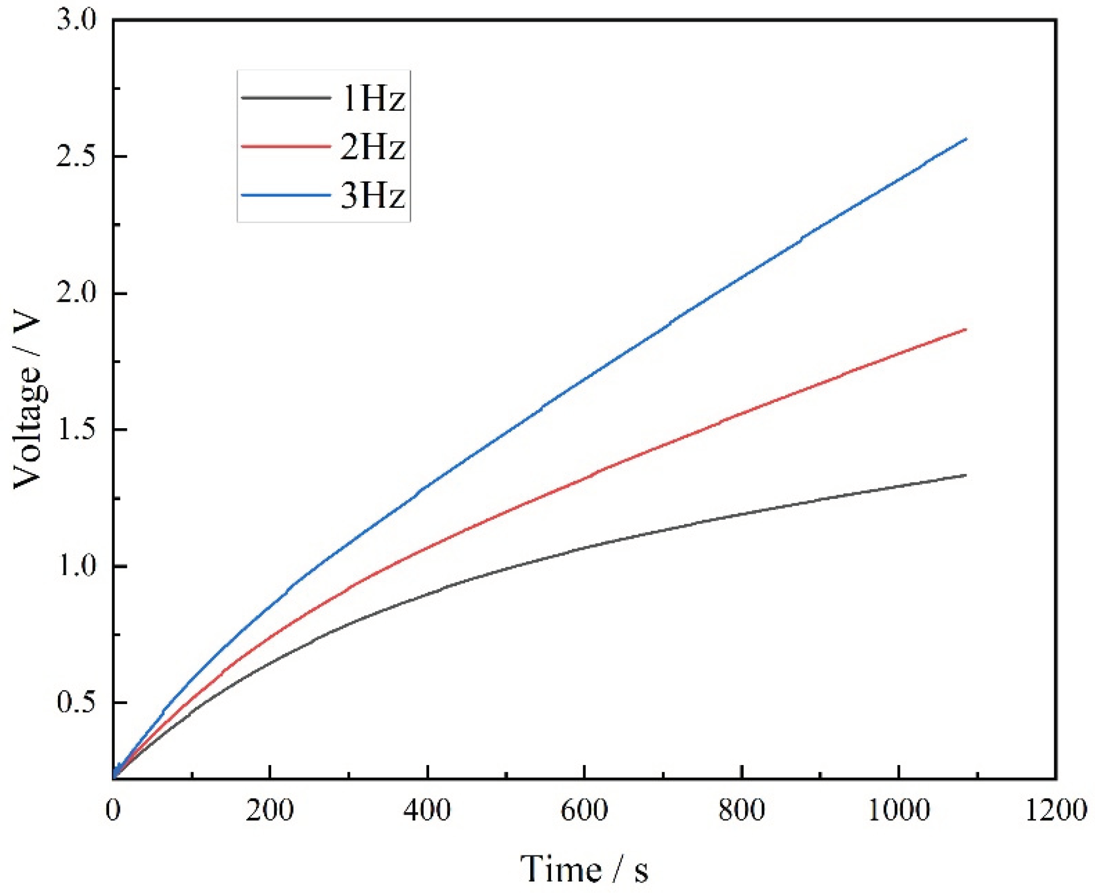
To explore the electrical signal characteristics produced by the FS-TENG under various mechanical motions, a FS-TENG with a 0.15% FS concentration was selected for experimentation. A 10 µF capacitor was integrated into the external circuit, and its charging behavior at different frequencies is depicted in
Figure 8. The results show that an increase in mechanical frequency leads to a quicker charging rate of the capacitor. Specifically, after 800 seconds of mechanical pressing, the FS-TENG operating at a frequency of 3 Hz generates almost double the electrical energy compared to that at 1 Hz. The FS-TENG yields distinct electrical signals in response to different mechanical pressure frequencies. Based on this capability, the FS-TENG can be utilized as a sensor to determine the movement frequencies of dynamic objects, such as automobile tires and sports shoes.
4. Discussion
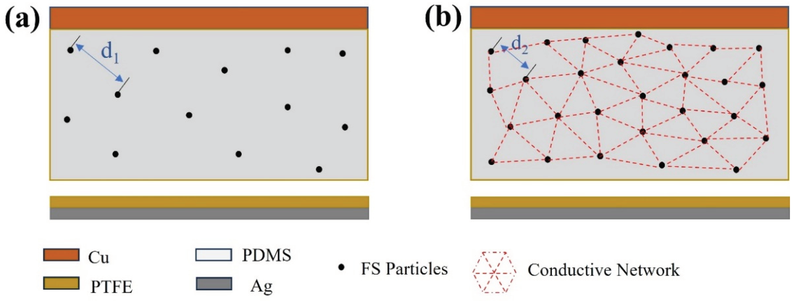
FS nanoparticles possess a high dielectric constant, and their incorporation into PDMS enhances the dielectric constant of the resultant composite film, thereby augmenting its capacitive properties. As depicted in
Figure 9a, the spherical structure of FS nanoparticles creates a porous structure within PDMS, which offers an extensive surface area and serves as charge trapping sites. These sites facilitate the generation of increased triboelectric charges during the triboelectrification process, consequently enhancing the energy conversion efficiency of the TENG [
31,
32,
33]. However, beyond a 0.15% addition of FS nanoparticles, the inter-particle spacing diminishes (as illustrated with d2 < d1 in
Figure 9), leading to electron migration between FS particles. This migration results in the formation of a conductive network, as shown in
Figure 9b, inducing significant dielectric loss and adversely impacting the output performance of the FS-TENG. This observation is corroborated by the trend of the transferred charge between electrodes, which initially rises and then falls with increasing FS content, as demonstrated in
Figure 3c.
5. Conclusions
In this study, we utilized cost-effective FS nanoparticles to enhance a TENG, which boasts a simplistic design yet effectively converts mechanical energy into electrical energy. The developed FS-TENG exhibits a maximum Voc of 18.49 V and Isc of 2.2 µA, achieving a peak power density of 145 µW/m² with a 63 MΩ load resistor. The electrical energy generated by the FS-TENG is sufficient to illuminate 72 LEDs. Moreover, this FS-TENG is capable of producing varying electrical signals in response to different mechanical energies harnessed, making it suitable as a sensor to monitor mechanical movements. This research contributes to advancing the deployment of TENGs with both low-cost and straightforward designs in sustainable energy and autonomous energy sensing applications.
Author Contributions
Conceptualization, S.Y. and W.Z.; methodology, O.T.; software, S.Y.; validation, W.Z. and T.L.; formal analysis, W.Z.; investigation, S.Y.; resources, O.T.; data curation, S.Y.; writing—original draft preparation, S.Y.; writing—review and editing, W.Z.; visualization, T.L.; supervision, T.L.; project administration, W.Z.; funding acquisition, W.Z. All authors have read and agreed to the published version of the manuscript.
Funding
The research was supported by “the Fundamental Research Funds for the Central Universities”, grant number 60201523011.
Informed Consent Statement
Not applicable.
Data Availability Statement
The datasets used and analyzed during the current study are available from the corresponding author upon reasonable request.
Conflicts of Interest
The authors declare no conflicts of interest.
References
- Li, X.; Zhang, C.; Gao, Y.; Zhao, Z.; Hu, Y.; Yang, O.; Liu, L.; Zhou, L.; Wang, J.; Wang, Z.L. A highly efficient constant-voltage triboelectric nanogenerator. Energy Environ. Sci. 2022, 15, 1334–1345. [Google Scholar] [CrossRef]
- Moreira, K.S.; da Campo, Y.A.S.; Lorenzett, E.; Burgo, T.A. Low-cost triboelectric nanogenerator based on aseptic carton package. Results Eng. 2023, 17. [Google Scholar] [CrossRef]
- Korkmaz, S.; Kariper. A. Production and applications of flexible/wearable triboelectric nanogenerator (TENGS). Synth. Met. 2021, 273, 116692. [Google Scholar] [CrossRef]
- Fu, W.; Turcheniuk, K.; Naumov, O.; Mysyk, R.; Wang, F.; Liu, M.; Kim, D.; Ren, X.; Magasinski, A.; Yu, M.; et al. Materials and technologies for multifunctional, flexible or integrated supercapacitors and batteries. Mater. Today 2021, 48, 176–197. [Google Scholar] [CrossRef]
- Xu, H.; Tao, J.; Liu, Y.; Mo, Y.; Bao, R.; Pan, C. Fully Fibrous Large-Area Tailorable Triboelectric Nanogenerator Based on Solution Blow Spinning Technology for Energy Harvesting and Self-Powered Sensing. Small 2022, 18, e2202477. [Google Scholar] [CrossRef] [PubMed]
- Salauddin, M.; et al. Highly Electronegative V2CTx/Silicone Nanocomposite-Based Serpentine Triboelectric Nanogenerator for Wearable Self-Powered Sensors and Sign Language Interpretation. Advanced Energy Materials 2023, 13. [Google Scholar] [CrossRef]
- Wang, Z.; et al. A Self-Powered Angle Sensor at Nanoradian-Resolution for Robotic Arms and Personalized Medicare. Advanced Materials 2020, 32. [Google Scholar] [CrossRef]
- Shao, J.; Yang, Y.; Yang, O.; Wang, J.; Willatzen, M.; Wang, Z.L. Designing Rules and Optimization of Triboelectric Nanogenerator Arrays. Adv. Energy Mater. 2021, 11, 2100065. [Google Scholar] [CrossRef]
- Lin, S.; Xu, L.; Xu, C.; Chen, X.; Wang, A.C.; Zhang, B.; Lin, P.; Yang, Y.; Zhao, H.; Wang, Z.L. Electron Transfer in Nanoscale Contact Electrification: Effect of Temperature in the Metal–Dielectric Case. Adv. Mater. 2019, 31, e1808197. [Google Scholar] [CrossRef]
- Lien, D.-H.; Amani, M.; Desai, S.B.; Ahn, G.H.; Han, K.; He, J.-H.; Ager, J.W.; Wu, M.C.; Javey, A. Large-area and bright pulsed electroluminescence in monolayer semiconductors. Nat. Commun. 2018, 9, 1–7. [Google Scholar] [CrossRef]
- Xu, Q.; Shang, C.; Ma, H.; Hong, Q.; Li, C.; Ding, S.; Xue, L.; Sun, X.; Pan, Y.; Sugahara, T.; et al. A guided-liquid-based hybrid triboelectric nanogenerator for omnidirectional and high-performance ocean wave energy harvesting. Nano Energy 2023, 109. [Google Scholar] [CrossRef]
- Zhang, L.; Cai, H.; Xu, L.; Ji, L.; Wang, D.; Zheng, Y.; Feng, Y.; Sui, X.; Guo, Y.; Guo, W.; et al. Macro-superlubric triboelectric nanogenerator based on tribovoltaic effect. Matter 2022, 5, 1532–1546. [Google Scholar] [CrossRef]
- Dong, L.; Wang, M.; Wu, J.; Zhu, C.; Shi, J.; Morikawa, H. Deformable Textile-Structured Triboelectric Nanogenerator Knitted with Multifunctional Sensing Fibers for Biomechanical Energy Harvesting. Adv. Fiber Mater. 2022, 4, 1486–1499. [Google Scholar] [CrossRef]
- Han, J.; Liu, Y.; Feng, Y.; Jiang, T.; Wang, Z.L. Achieving a Large Driving Force on Triboelectric Nanogenerator by Wave-Driven Linkage Mechanism for Harvesting Blue Energy toward Marine Environment Monitoring. Adv. Energy Mater. 2022, 13. [Google Scholar] [CrossRef]
- Tan, D.; Zeng, Q.; Wang, X.; Yuan, S.; Luo, Y.; Zhang, X.; Tan, L.; Hu, C.; Liu, G. Anti-Overturning Fully Symmetrical Triboelectric Nanogenerator Based on an Elliptic Cylindrical Structure for All-Weather Blue Energy Harvesting. Nano-Micro Lett. 2022, 14, 1–12. [Google Scholar] [CrossRef]
- Jiao, P.; Nazar, A.M.; Egbe, K.-J.I.; Barri, K.; Alavi, A.H. Magnetic capsulate triboelectric nanogenerators. Sci. Rep. 2022, 12, 1–10. [Google Scholar] [CrossRef] [PubMed]
- Paosangthong, W.; Wagih, M.; Torah, R.; Beeby, S. Textile-based triboelectric nanogenerator with alternating positive and negative freestanding woven structure for harvesting sliding energy in all directions. Nano Energy 2021, 92, 106739. [Google Scholar] [CrossRef]
- Lee, D.-M.; Rubab, N.; Hyun, I.; Kang, W.; Kim, Y.-J.; Kang, M.; Choi, B.O.; Kim, S.-W. Ultrasound-mediated triboelectric nanogenerator for powering on-demand transient electronics. Sci. Adv. 2022, 8, eabl8423. [Google Scholar] [CrossRef]
- Han, J.; Feng, Y.; Chen, P.; Liang, X.; Pang, H.; Jiang, T.; Wang, Z.L. Wind-Driven Soft-Contact Rotary Triboelectric Nanogenerator Based on Rabbit Fur with High Performance and Durability for Smart Farming. Adv. Funct. Mater. 2021, 32, 2108580. [Google Scholar] [CrossRef]
- Hu, S.; Yuan, Z.; Li, R.; Cao, Z.; Zhou, H.; Wu, Z.; Wang, Z.L. Vibration-Driven Triboelectric Nanogenerator for Vibration Attenuation and Condition Monitoring for Transmission Lines. Nano Lett. 2022, 22, 5584–5591. [Google Scholar] [CrossRef]
- Ning, C.; Cheng, R.; Jiang, Y.; Sheng, F.; Yi, J.; Shen, S.; Zhang, Y.; Peng, X.; Dong, K.; Wang, Z.L. Helical Fiber Strain Sensors Based on Triboelectric Nanogenerators for Self-Powered Human Respiratory Monitoring. ACS Nano 2022, 16, 2811–2821. [Google Scholar] [CrossRef] [PubMed]
- Fan, F.-R.; Tian, Z.-Q.; Wang, Z.L. Flexible triboelectric generator. Nano Energy 2012, 1, 328–334. [Google Scholar] [CrossRef]
- Salauddin; Rana, S.M.S.; Rahman, M.T.; Sharifuzzaman; Maharjan, P.; Bhatta, T.; Cho, H.; Lee, S.H.; Park, C.; Shrestha, K.; et al. Fabric-Assisted MXene/Silicone Nanocomposite-Based Triboelectric Nanogenerators for Self-Powered Sensors and Wearable Electronics. Adv. Funct. Mater. 2021, 32, 2107143. [Google Scholar] [CrossRef]
- Jin, L.; Xiao, X.; Deng, W.; Nashalian, A.; He, D.; Raveendran, V.; Yan, C.; Su, H.; Chu, X.; Yang, T.; et al. Manipulating Relative Permittivity for High-Performance Wearable Triboelectric Nanogenerators. Nano Lett. 2020, 20, 6404–6411. [Google Scholar] [CrossRef] [PubMed]
- Shrestha, K.; et al. A Siloxene/Ecoflex Nanocomposite-Based Triboelectric Nanogenerator with Enhanced Charge Retention by MoS2/LIG for Self-Powered Touchless Sensor Applications. Advanced Functional Materials 2022, 32. [Google Scholar] [CrossRef]
- Huang, J.; Fu, X.; Liu, G.; Xu, S.; Li, X.; Zhang, C.; Jiang, L. Micro/nano-structures-enhanced triboelectric nanogenerators by femtosecond laser direct writing. Nano Energy 2019, 62, 638–644. [Google Scholar] [CrossRef]
- Liu, Z.; Huang, Y.; Shi, Y.; Tao, X.; He, H.; Chen, F.; Huang, Z.-X.; Wang, Z.L.; Chen, X.; Qu, J.-P. Fabrication of triboelectric polymer films via repeated rheological forging for ultrahigh surface charge density. Nat. Commun. 2022, 13, 1–10. [Google Scholar] [CrossRef]
- Yao, G.; Kang, L.; Li, C.; Chen, S.; Wang, Q.; Yang, J.; Long, Y.; Li, J.; Zhao, K.; Xu, W.; et al. A self-powered implantable and bioresorbable electrostimulation device for biofeedback bone fracture healing. Proc. Natl. Acad. Sci. 2021, 118. [Google Scholar] [CrossRef] [PubMed]
- Su, M.; Brugger, J.; Kim, B. Simply Structured Wearable Triboelectric Nanogenerator Based on a Hybrid Composition of Carbon Nanotubes and Polymer Layer. Int. J. Precis. Eng. Manuf. Technol. 2020, 7, 683–698. [Google Scholar] [CrossRef]
- Yang, H.J.; Lee, J.-W.; Seo, S.H.; Jeong, B.; Lee, B.; Do, W.J.; Kim, J.H.; Cho, J.Y.; Jo, A.; Jeong, H.J.; et al. Fully stretchable self-charging power unit with micro-supercapacitor and triboelectric nanogenerator based on oxidized single-walled carbon nanotube/polymer electrodes. Nano Energy 2021, 86. [Google Scholar] [CrossRef]
- Saadatnia, Z.; Mosanenzadeh, S.G.; Esmailzadeh, E.; Naguib, H.E. A High Performance Triboelectric Nanogenerator Using Porous Polyimide Aerogel Film. Sci. Rep. 2019, 9, 1–12. [Google Scholar] [CrossRef] [PubMed]
- Harnchana, V.; Van Ngoc, H.; He, W.; Rasheed, A.; Park, H.; Amornkitbamrung, V.; Kang, D.J. Enhanced Power Output of a Triboelectric Nanogenerator using Poly(dimethylsiloxane) Modified with Graphene Oxide and Sodium Dodecyl Sulfate. ACS Appl. Mater. Interfaces 2018, 10, 25263–25272. [Google Scholar] [CrossRef] [PubMed]
- Wu, C.; Kim, T.W.; Choi, H.Y. Reduced graphene-oxide acting as electron-trapping sites in the friction layer for giant triboelectric enhancement. Nano Energy 2017, 32, 542–550. [Google Scholar] [CrossRef]
|
Disclaimer/Publisher’s Note: The statements, opinions and data contained in all publications are solely those of the individual author(s) and contributor(s) and not of MDPI and/or the editor(s). MDPI and/or the editor(s) disclaim responsibility for any injury to people or property resulting from any ideas, methods, instructions or products referred to in the content. |
© 2024 by the authors. Licensee MDPI, Basel, Switzerland. This article is an open access article distributed under the terms and conditions of the Creative Commons Attribution (CC BY) license (http://creativecommons.org/licenses/by/4.0/).
