1. Introduction
Typhoon is one of the major natural disasters threatening China’s southeast coasts, causing much damages on buildings and infrastructures, including transmission tower-line systems of the power grid. The transmission tower-line system is a typical wind-sensitive structure with the characteristics of high flexibility, long span, and strong geometric non-linearity [
1]. In 2005, typhoon “Damrey” caused the collapse of the power system of Hainan [
2]; During hurricane “Sandy” in 2012 and hurricane “Irene” in 2011, over 200 transmission towers failed [
3]; In 2015, the super typhoon “Mujigae” damaged 80 towers, impacting thousands of transmission lines [
4]. Anthropogenic climate change has already substantially increased the exposure to extreme climate impact events worldwide, and further global warming is projected to exacerbate the weather hazards as we already see today [
5]. Huang [
6] indicates that under the backdrop of anthropogenic warming, both the landfall intensity and precipitation of typhoons in the southeastern coastal areas of China are expected to increase. The risk of typhoon-induced disasters on Southeast China is also significantly elevated [
6].
The structural damage to transmission tower-line systems during typhoon weather can be attributed to strong winds and heavy rainfall. Burgh and Harton [
7], as well as Burgh et al. [
8], proposed a model equation to investigate rain-wind induced vibrations in a simple oscillator. They discovered that variations in the detuning parameter can result in saddle-node and Hopf bifurcations. Deng and Yang conducted numerical simulations [
9,
10] to study the response of a tower-line system under windy conditions. An's research [
11,
12], based on numerical simulations, considered the combined effects of wind and rain. However, their study primarily focused on the structural failure of towers. Some researchers analyzed the windage yaw of insulator strings and wires due to wind and rain loads. Yan et al. [
13] introduced a numerical model of a transmission line section to calculate the dynamic swing of the suspension insulator. Zhou [
14] proposed a model with a derived stability criterion to analyze the significant swing of the overhead conductor under wind and rain conditions. Fu and Li [
15,
16] established a calculation method for wind and rain loads on transmission conductors and discussed the effects of wind and rain excitation. Their results indicate that rain loads relative to wind loads could reach up to 22%. Zhou et al. [
17,
18] developed a two-dimensional model to investigate rain-wind induced vibration in transmission lines and discussed the aerodynamic instability zone using the Lyapunov stability criterion.
With the rapid progress of high-performance computation technique, numerical weather prediction (NWP) becomes an effective method to analyze the wind-rain climates and meteorological variables [
19]. Weather research and forecasting model (WRF) is one of the most widely used NWP system designed for atmospheric research and operational weather forecasting. It is a state-of-the-art modeling system that simulates the dynamics and physics of the atmosphere to generate detailed weather forecasts and conduct meteorological research. WRF has gained popularity due to its flexibility, scalability, and ability to simulate a wide range of meteorological phenomena. The Advanced Research WRF (ARW) is one of the dynamical cores available within the WRF model based on a fully compressible set of atmospheric equations and is an appropriate model for simulating tropical cyclone systems. Many researchers have conducted typhoon related studies based on the ARW model and found that the ARW model could reproduce atmospheric conditions and agree well with the measurements during typhoons [
20,
21,
22,
23,
24].
The coupled phenomena of wind and rain is referred to as wind-driven rain (WDR), that is, raindrops carried obliquely by strong winds. It occurs when raindrops get horizontal velocity component from wind blows, rather than falling straight down vertically. Wind-driven rain can lead to water intrusion, moisture damage, and potential issues like leaks, rot, or mold growth, affecting the thermal and moisture performance of buildings [
25]. Researches have been carried out to study the WDR on building facades with full-scale measurements [
26,
27], semi-empirical methods [
28,
29], and numerical simulations. Although the numerical simulation of WDR with computational fluid dynamics (CFD) is complex and time-consuming, it can accurately determine the temporal and spatial distribution of WDR on complicated building facades, and the simulation accuracy has been validated with field measurements [
30,
31,
32,
33,
34].
In this paper, a multiscale numerical framework is developed based on the WRF-CFD and FEM method to solve the WDR effects on the motion of a span of transmission lines located in Zhoushan island. Compared to existing researches, the presented method enables the prediction of the dynamic responses of transmission lines under real weather conditions based on multi-scale models coupling, and provides an insight into the wind-driven rain effect on conductors by means of multiphase CFD simulation.
Section 2 proposes the methodology of the numerical simulation.
Section 3 details the configurations of WRF model and presents the simulation results of Typhoon Lekima (2019).
Section 4 presents the CFD simulation based on Eulerian Multiphase (EM) model of WDR flow field.
Section 5 shows the finite element analysis of the transmission line under WDR condition.
Section 6 provides discussion and conclusions.
2. Methods
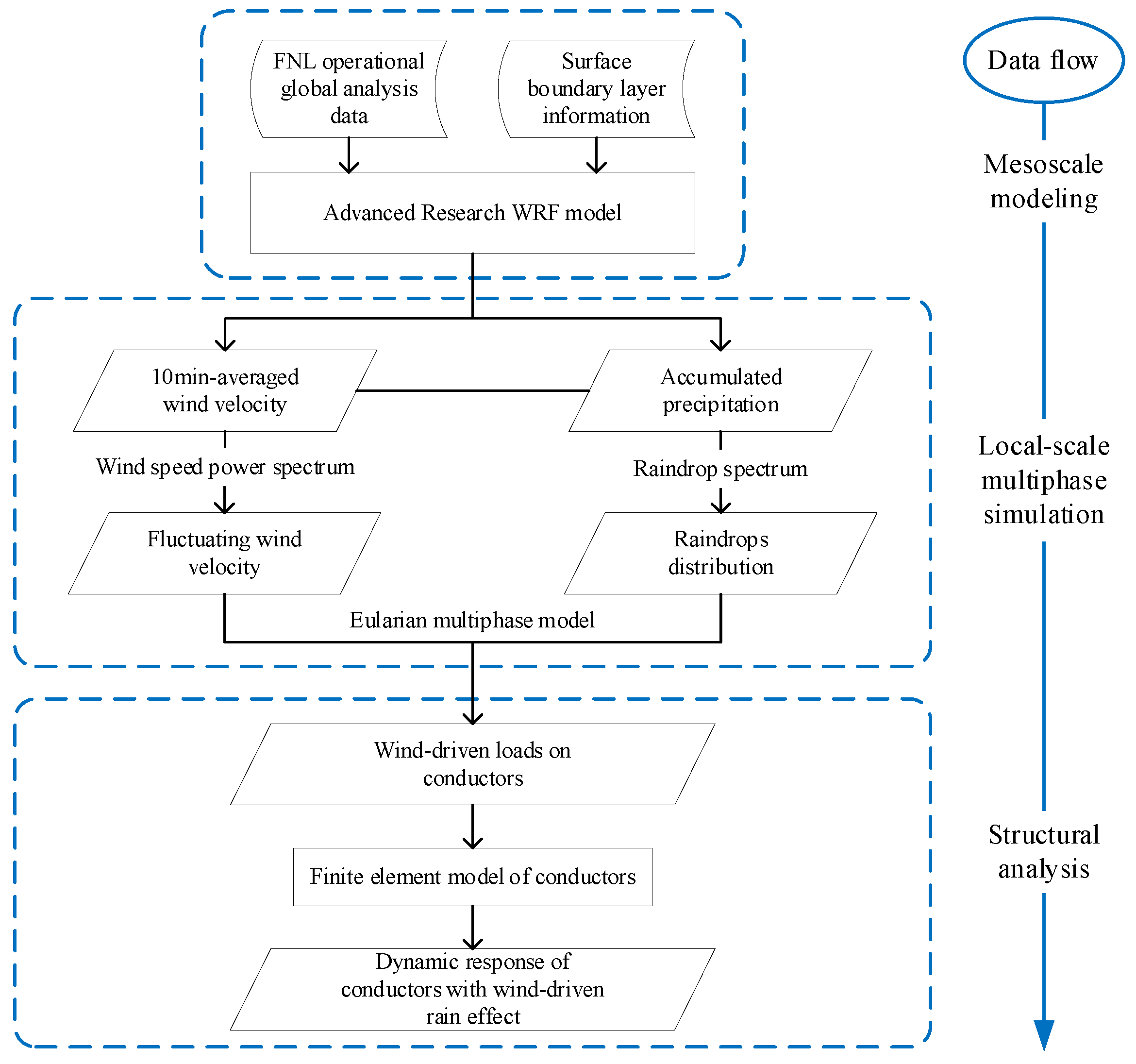
Figure 1 demonstrates the workflow of the numerical simulation of WDR effects on a transmission line during a typhoon event. The framework consists of a mesoscale typhoon simulation through WRF, a CFD model of WDR multiphase flow and a finite element model of transmission line conductors.
2.1. Model Equations in WRF
The compressible, non-hydrostatic governing equations, i.e., time-averaged Reynolds equations, that govern the mesoscale NWP model are cast in flux forms and can be expressed in a terrain-following hydrostatic-pressure vertical coordinate as in literature [
35,
36]. Modelling of clouds microphysical process plays an important role in mesoscale convective storm simulations. The WRF Double-Moment 6-class (WDM6) microphysics scheme [
37] is applied in this study. It is a bulk parameterization scheme that contains six water species: water vapor, cloud droplets, cloud ice, snow, rain, and graupel. Cloud particles are represented as particle size distribution (PSD) functions and are characterized by their moments in modelling of physical processes. The cloud-raindrop size distribution in WDM6 follows the normalized form given by [
37],
where
refers to clouds or rain respectively;
is the corresponding slope parameter, whereas
and
are the two dispersion parameters.
The governing equation of the number concentration for each species is expressed as,
where the first and second terms in the RHS represent the 3D advection and sedimentation for
, respectively. The term
represents the source and sink of number concentration for
.
The number-weighted-mean terminal velocity which is responsible for the sedimentation of the rain number concentration can be obtained by integrating the terminal velocity of rain water,
where
represents the terminal velocity of rain particles with diameter
. Based on Locatelli and Hobbs [
38], the expression is given by,
2.2. WDR Simulation by Eulerian Multiphase Model
Under severe convective weather conditions, the coupled effect of strong wind and extreme rainfall will increase the load on transmission lines, and the rain water adhering to conductor surface can significantly change its aerodynamic characteristics. The WDR loads is related to the interaction of raindrops of different sizes with the wind flow. In the EM model, rain is regarded as various continuum and dilute phases with equivalent raindrop sizes, reducing the computation cost compared to Lagrangian Particle Tracking (LPT) model. Raindrops are divided into
N groups according to the diameter
D, and the
kth rain phase represents the collection of raindrops of which the diameter
,
k=1, 2, …, N, where
is the
kth diameter and
. The mass and momentum conservation equations for
kth rain phase are presented as follows [
30],
where
and
are the density of water and air respectively;
is the volume fraction of the
kth rain phase;
and
represent the velocity vector of wind and the
kth rain phase respectively;
is the gravity along
i direction;
is the dynamic viscosity of air;
is the drag coefficient;
represents the relative Reynolds number.
The second term on the RHS of Eq. (5) stands for the dragging of the wind flow. A raindrop in equilibrium state gives,
where
is the terminal velocity of raindrops with diameter
D, and can be calculated by [
38],
Then the drag coefficient
is constructed in the following form to hold Eq. (9),
2.3. Segment Model of Overhead Conductors under WDR Condition
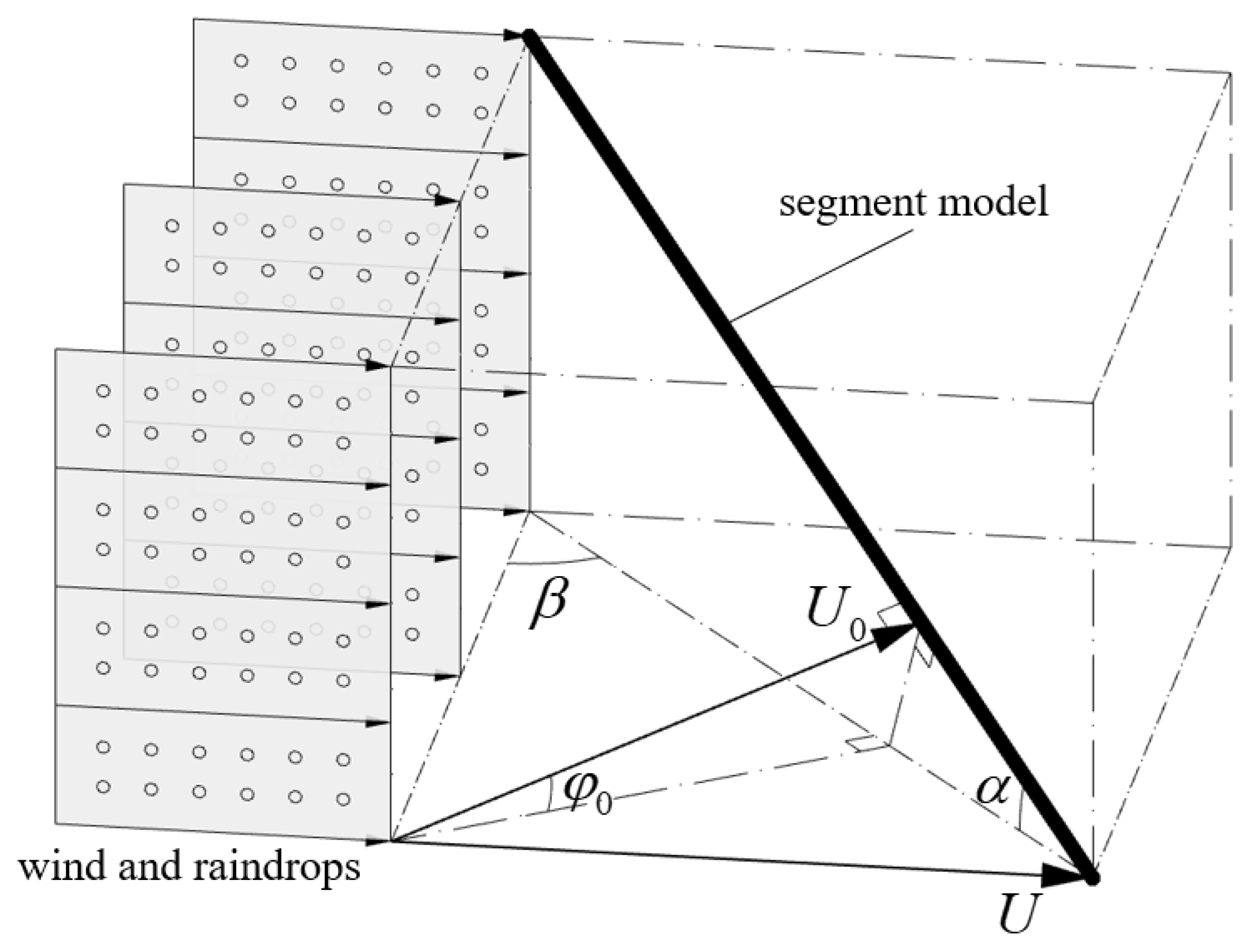
The overhead conductor is hung with suspension insulator strings between transmission towers. A segment model of the conductor is depicted in
Figure 2. In this model, the conductor segment is simplified as a cylinder, and
is the inclination of the segment;
is the wind angle towards the segment;
is the inflow wind velocity. The impact of WDR on conductor loads can be divided into two parts: the effect of raindrop impingement and the influence of rivulets on aerodynamic characteristic. According to Zhou [
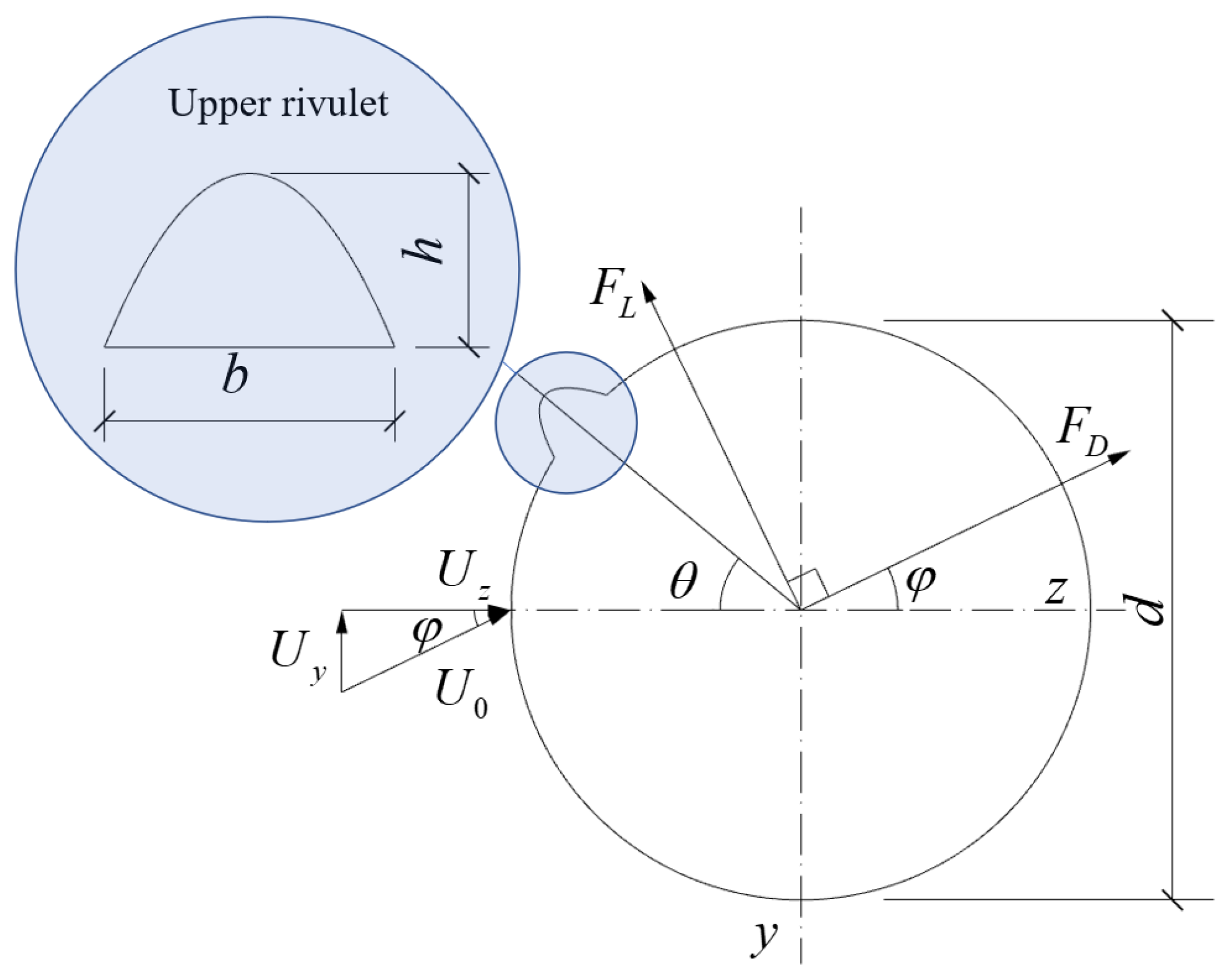
14], the wind-driven rain is sufficient to create upper and lower rivulets along the conductor while the lower rivulet is assumed to make little difference to the aerodynamic coefficients of the conductor and is neglected in this paper.
Figure 3 shows the cross-section of the conductor. Under a certain rain-wind condition, upper rivulet occurs at the surface of the cylinder. Relative size of the height and the width to the diameter of the conductor are about 0.10 and 0.17 [
17]. The balance angle of the upper rivulet is
, determined by the coupled actions of gravity force, surface tension, and rain-wind loads. The unstable angle of the upper rivulet
oscillates around
and the vibration of the rivulet can be considered harmonic [
17,
40]. Yet for simplicity, we assumed that the relative position of upper rivulet and conductor surface is fixed, that is,
.
The component of the wind velocity
, perpendicular to the cylinder, can be expressed as,
The initial attack angle is defined as,
The along-wind direction aerodynamic force per unit length of the cylinder can be expressed as,
where
is the aerodynamic force coefficient and
;
is the air density;
is the diameter of the cylinder.
The aerodynamic force coefficient
is derived as,
where
and
are the aerodynamic drag and lift force coefficients, respectively.
is the instantaneous relative wind velocity, and its horizontal and vertical component can be computed as,
where
and
are the horizontal and vertical velocity of the cylinder, respectively.
3. Simulation of Typhoon Lekima
3.1. Overview of Lekima and WRF Model Settings
Super Typhoon Lekima in 2019, designated as No.1909, was a powerful and destructive tropical cyclone that struck East Asia in August 2019. It was the ninth named storm and the fourth typhoon of the 2019 Pacific typhoon season. Lekima originated from a tropical depression that formed east of the Northern Mariana Islands on July 30, 2019. The storm gradually intensified as it moved west-northwestward, reaching typhoon status on August 6. It continued to strengthen rapidly and became a super typhoon on August 7, with maximum sustained winds of 62 m/s. Lekima then made landfall in Wenling, Zhejiang province, China, on August 10. The impact of Typhoon Lekima was severe, causing widespread destruction and loss of life. It triggered torrential rainfall and strong winds, resulting in widespread flooding, landslides, and mudslides. The storm caused significant damage to infrastructure, including buildings, bridges and roads. It also disrupted transportation and led to power outages in several areas. According to the news report, Lekima has affected over 4 million people in Zhejiang Province. Crop damage has occurred on 103,000 hectares of land, with 13,000 hectares suffering complete crop loss. Additionally, over 14,000 houses have been damaged or collapsed due to the disaster, resulting in a direct economic loss of 7.44 billion yuan.
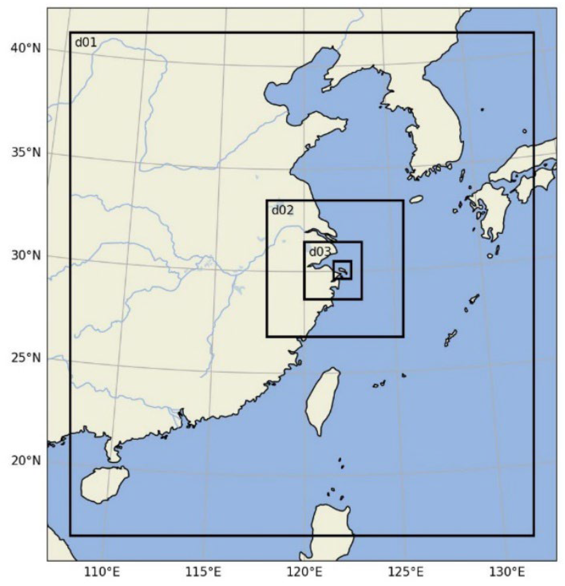
As demonstrated in
Figure 4, two-way nested static downscaling domains are used in WRF simulation and the simulation time period is from 0000 UTC 07 Aug to 0000 UTC 13 Aug in 2019. For the initial and boundary conditions of the outermost domain, 6-hourly Final Operational Global Analysis data of 1° resolution from the National Centers for Environmental Prediction (NCEP) are used, while the boundary conditions of the inner domains are provided by the domain above. The spatial and temporal resolutions of each domain are listed in
Table 1. The schemes and parameterizations of physical processes of the simulation are listed in
Table 2.
3.2. Simulated Tracks and Intensity
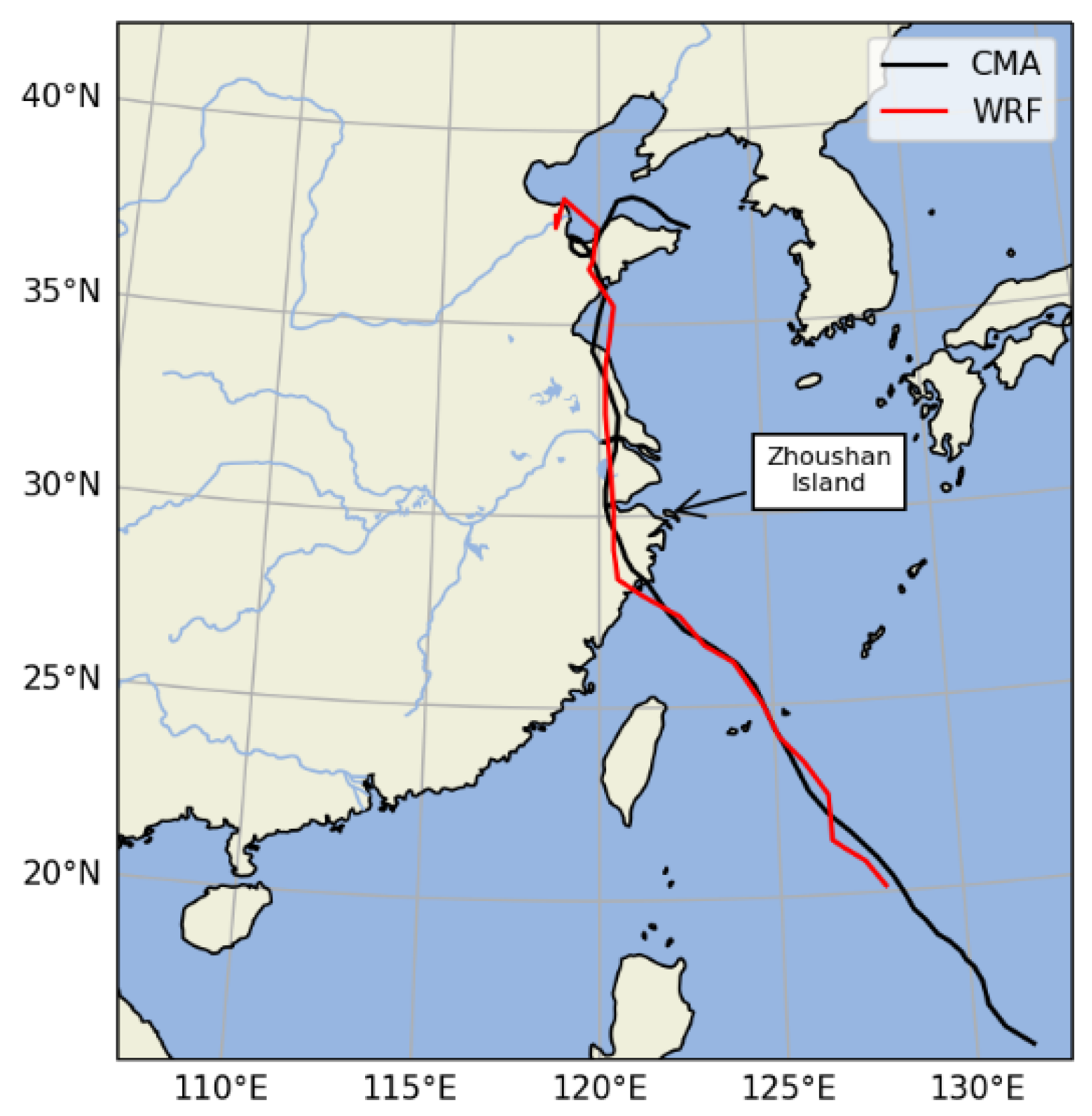
Figure 5 shows the result of the simulated track and CMA best track records [
41,
42] (
https://tcdata.typhoon.org.cn). As we can see, the ARW model fully reproduces the movement trajectory of the typhoon's first landfall, reentry into the sea, and subsequent landfall and the simulated track closely matches the observation.
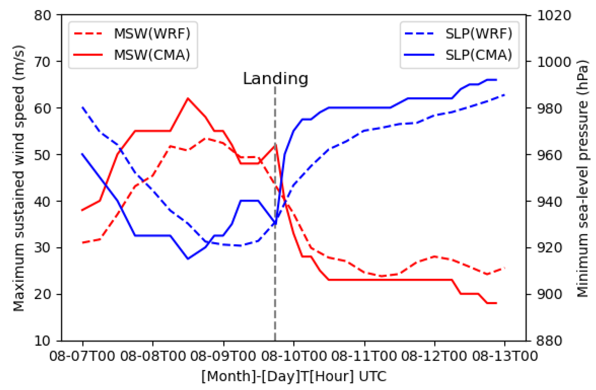
Figure 6 presents the time series of the minimum sea level pressure (SLP) and the maximum sustained wind (MSW) velocity derived from simulation and CMA observation. Before making landfall in Zhejiang, the simulation underestimates the intensity of Lekima with lower MSW and higher minimum SLP, while the intensity results are in good agreement with observations after landfall.
3.3. Simulated Wind Field and Precipitation
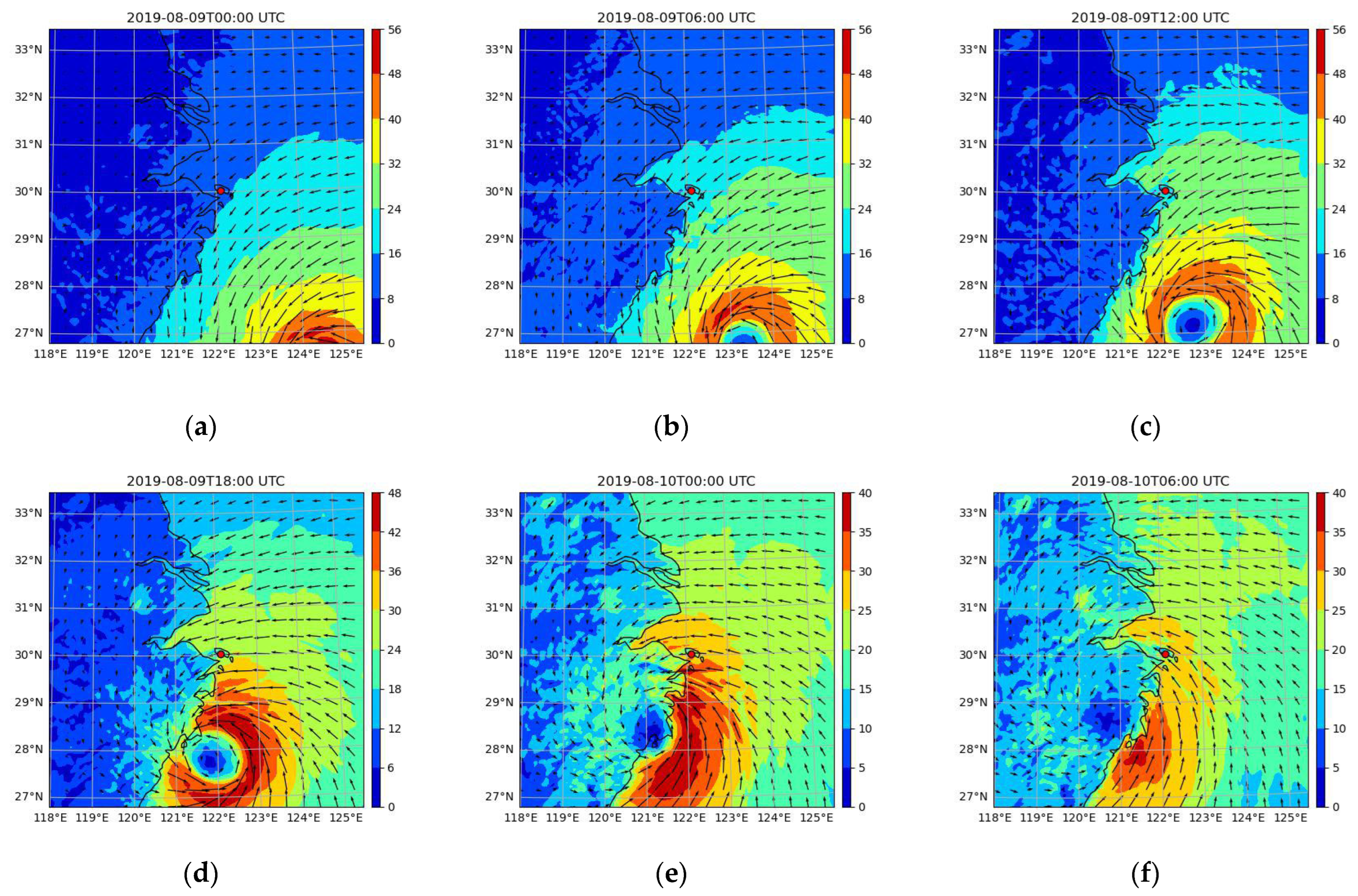
The evolution of typhoon wind field from 0000 UTC 09 Aug to 0060 UTC 10 Aug 2019 at 30m above the ground level in WRF d02 domain is plotted with a time interval of 6 hours in
Figure 7 (Zhoushan island is marked with a red dot). It shows that the ARW model successfully captured the process of Lekima gradually approaching Zhejiang and reducing its intensity immediately when reaching the coastal area before making landfall due to the mechanical dragging. During this process, the local wind velocity in Zhoushan island was greatly influenced by the mesoscale spiral structure of Lekima.
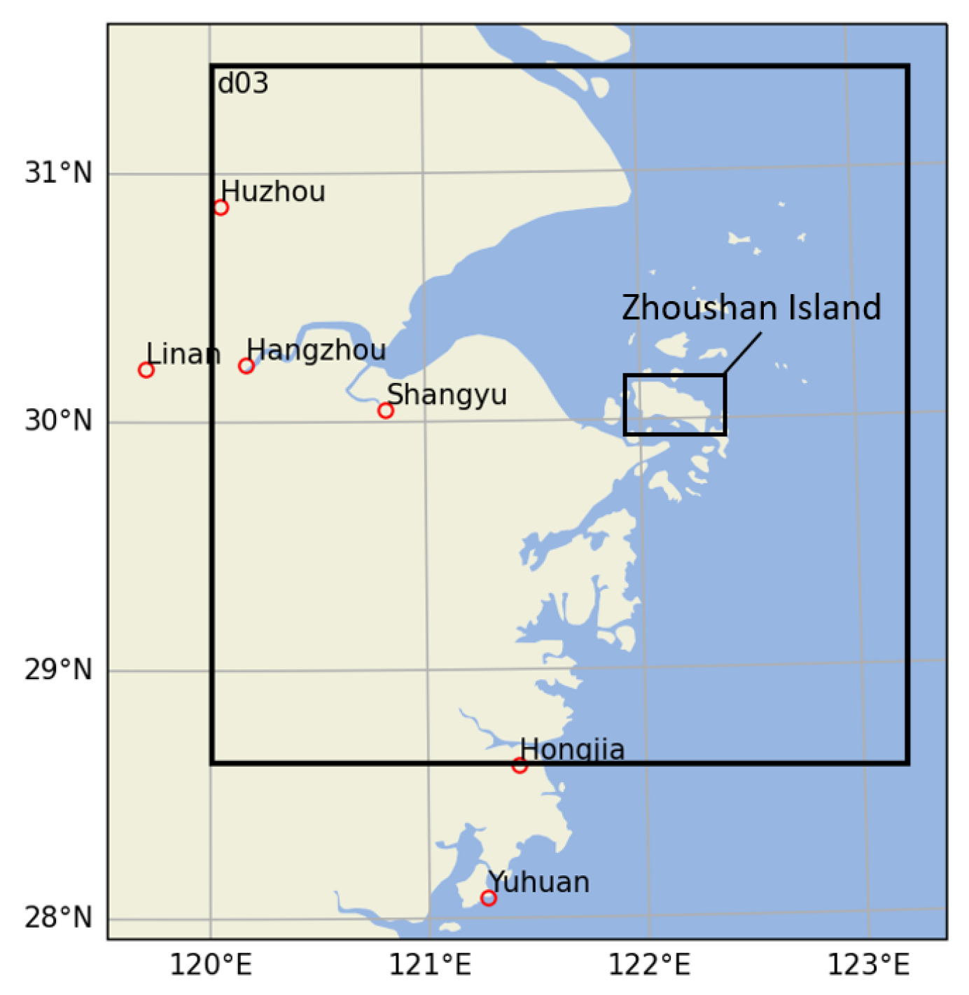
Figure 7 marks the location of six ground meteorological stations near the east coast of China and
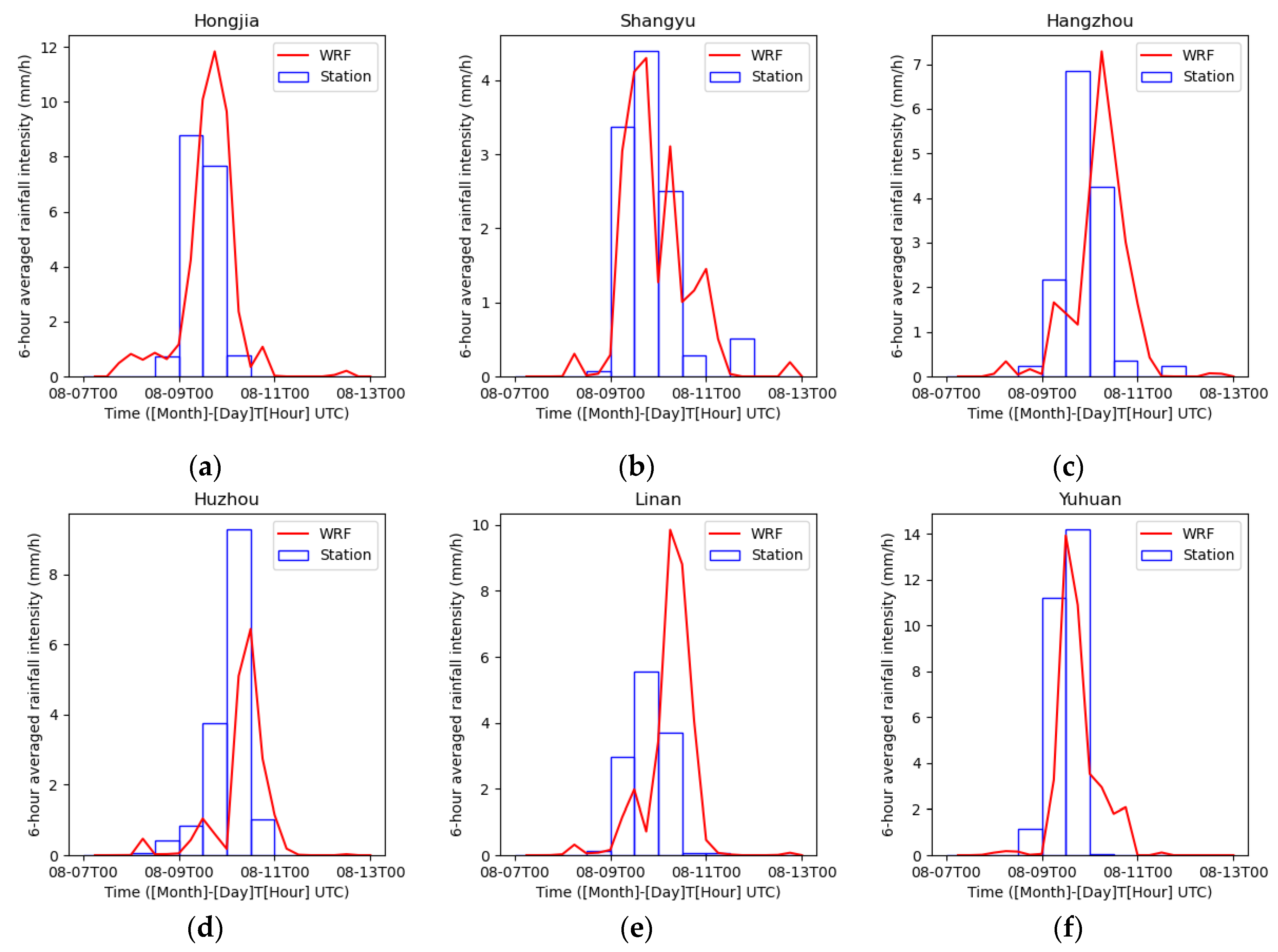
Figure 8 compares the simulated 6-h averaged rainfall intensity at these stations with the observation data obtained from China Meteorological Data Service Centre (
https://data.cma.cn/). It shows that extreme heavy rainfall occurs from 0000 UTC 09 Aug to 1200 UTC 10 Aug and the ARW model reproduced the rainfall event successfully. The simulated rainfall intensity at coastal stations (Shangyu, Hongjia and Yuhuan) match the observation more closely, compared to the inland areas (Huzhou, Linan, Hangzhou), because the complex surface condition increases the uncertainty of precipitation simulation. The simulated results indicate that the proposed WRF method could regenerate the whole process of typhoon events and reproduce the strong wind fields and local extreme heavy rainfall with a reasonable accuracy.
Figure 7.
Simulated wind field at 30m above the ground level in WRF d02 domain.
Figure 7.
Simulated wind field at 30m above the ground level in WRF d02 domain.
Figure 8.
Location of six meteorological stations in Zhejiang province.
Figure 8.
Location of six meteorological stations in Zhejiang province.
Figure 9.
6-hour averaged rainfall intensity at six meteorological stations during Lekima.
Figure 9.
6-hour averaged rainfall intensity at six meteorological stations during Lekima.
4. Wind-Driven Rain Load on Conductor
After the mesoscale WRF simulation of Lekima, local wind field and rainfall intensity in Zhoushan island is obtained, and the subsequent procedure of our simulation system is to solve the coupled wind and rain field around the transmission line and find out the WDR load on conductors. The WDR simulation would be carried out on 0000 UTC 10 Aug with the mean wind speed of
, the wind angle of
and the rainfall intensity of
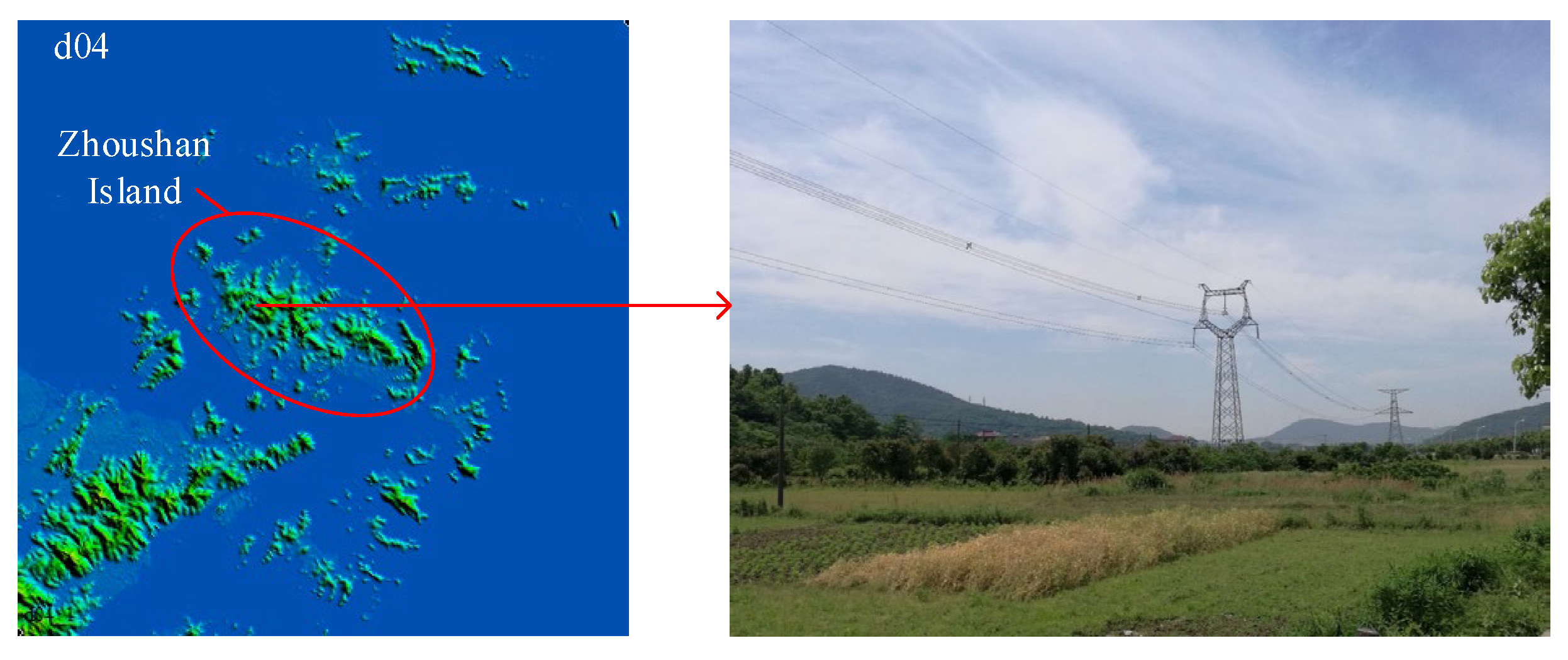
for the targeted transmission line in Zhoushan island as shown in
Figure 10. Two-dimensional computational domains and meshes of the fluid region around the cross-section of the conductor are established as presented in
Figure 11. Based on the drag coupling between rain phases and wind phase, the horizontal raindrop velocities are assumed to be equal to the inflow wind velocity, and the vertical velocities of rain phases are set by Eq. (10). The phase volume fraction
at the inlet boundary can be calculated as,
where
is the rainfall intensity;
represents the volume fraction of raindrops with diameter
D in all raindrops passing through a unit area horizontal plane in unit time, i.e., flux fraction, can be calculated as,
where
is the raindrop size distribution function which follows the modified
distribution proposed by de Wolf [
40], and is expressed as,
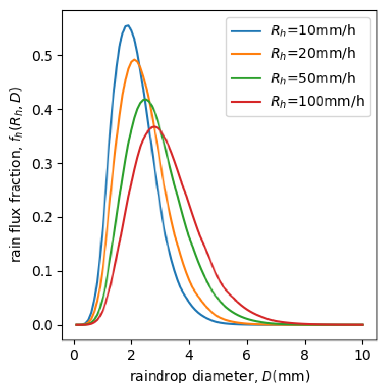
Figure 12 presents the rain phase flux fraction with different rainfall intensities. According to the illustrated raindrop size distribution, the discretized raindrop sizes are set to be
with the increment
as inlet rain condition, for the WDR simulation of rainfall intensity
.
The volume fraction and raindrop velocities at the top boundary are defined in the same way as the inlet boundary condition. The boundary conditions at the bottom, outflow boundary and the conductor surface are defined as,
where
is the unit normal vector pointing out of the computational domain. The first expression in Eq. (24) indicates that the raindrops will impact the solid surface just like no blocking. Therefore, based on the momentum theorem, the rain load caused by raindrop impact can be calculated as [
44],
where
and
refers to the rain phase pressure produced by the momentum loss in the normal and tangential direction, respectively.
and
are the velocity of rain phase with diameter
towards the solid surface along normal and tangential direction, respectively. Then the
and
under WDR condition can be derived from the summation of wind pressure and rain phase pressure as,
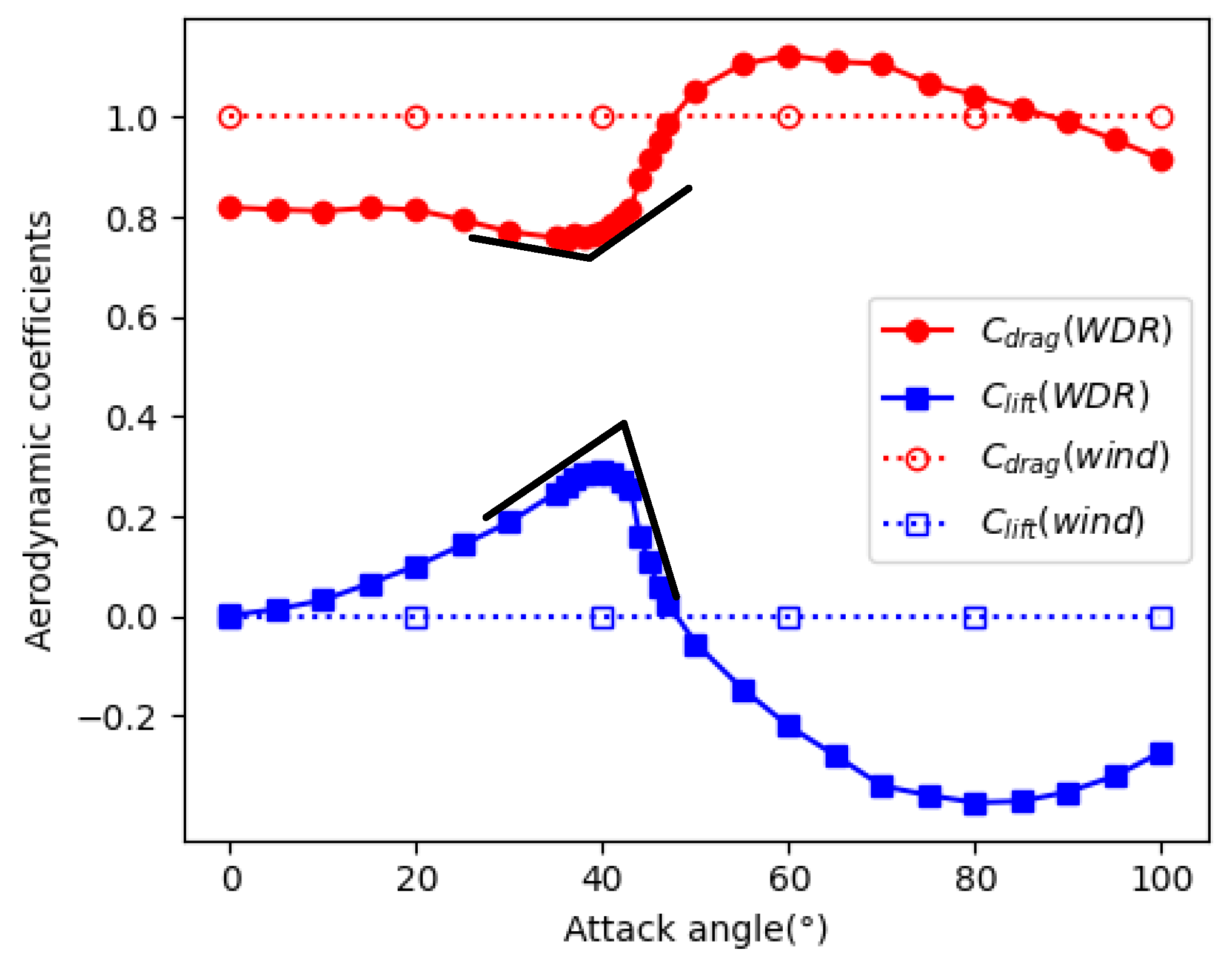
Figure 13 shows the simulated drag and lift coefficients of the conductor with upper rivulet under coupled wind and rain condition. Compared to cases without rain, both the drag and lift coefficients exhibit obvious variation from the constant results without rain. The result shows that the derivative of drag coefficients with respect to angle suddenly changed from negative to positive, and the derivative of lift coefficients changed from positive to negative when the attack angle
, which is the critical angle causing boundary layer to trip and influencing the location of the separation point [
14].
5. Motion of Conductor under WDR
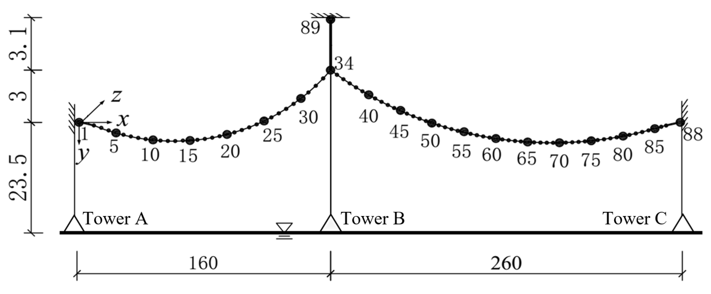
The transmission line in Zhoushan island consists of two spans of 160 m and 260 m. Each sub-conductor of the quad-bundled conductor is made of JL/G1A-300/25, the physical parameters of which are listed in
Table 3. In the table,
is the calculated cross-sectional area of the conductor;
is the outer diameter;
is the mass per unit length;
is the elastic modulus;
is the tensile strength of the conductor. To improve computational efficiency, the four sub-conductors of the quad-bundled conductor are modelled as a single equivalent conductor. The cross-sectional area, mass per unit length, and other physical parameters are adjusted accordingly for the single equivalent conductor to create a simplified two-span transmission line model, as shown in
Figure 14.
For applying wind or WDR loads, total 89 loading nodes are defined along the transmission line in
Figure 14. The mean wind velocity and rainfall intensity affecting the transmission line during Lekima in terms of WDR loads are derived from the WDR simulation as presented in
Section 4. Local turbulence wind fields are numerically generated by the spectral representation method [
45].
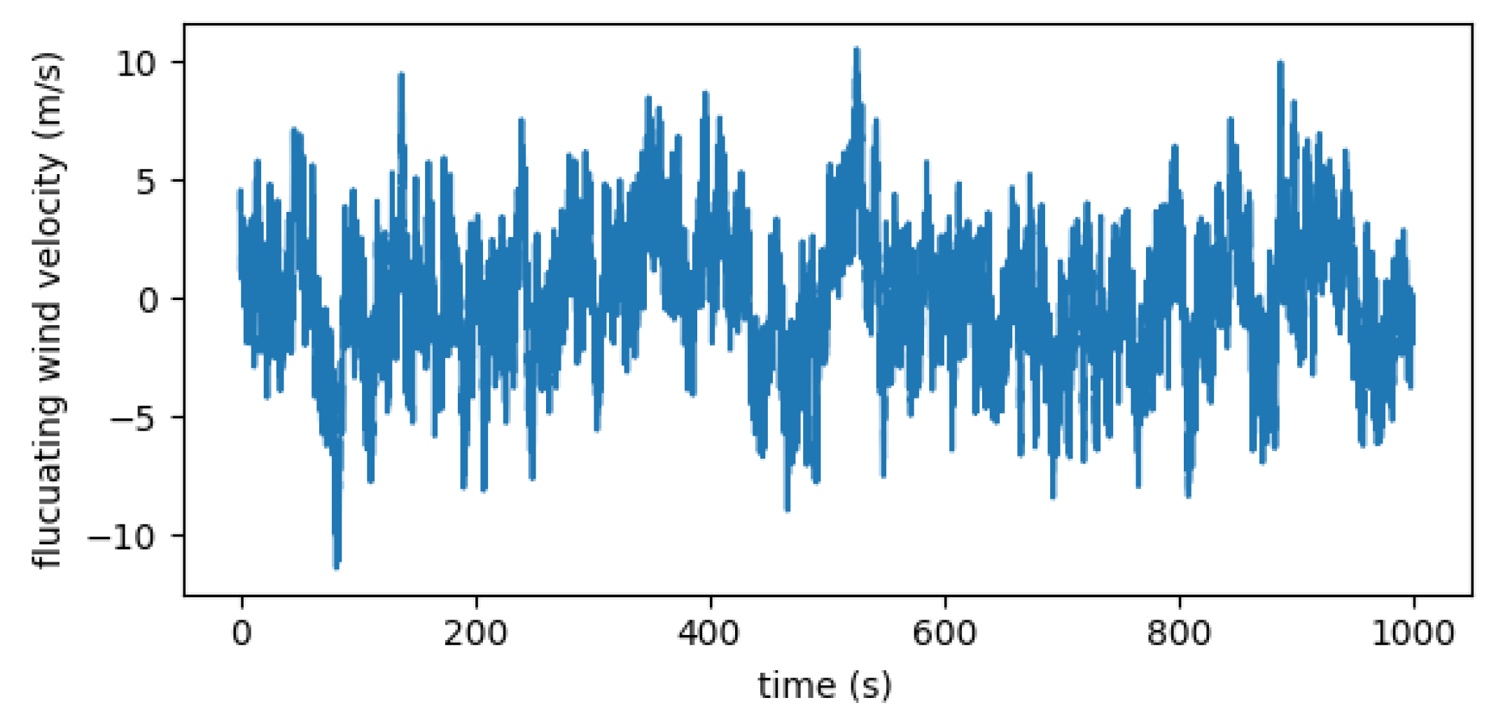
Figure 15 shows the generated fluctuating wind velocity at node 34.
According with the derived wind-driven rain meteorological condition and the aerodynamic force coefficients presented in
Figure 13, the wind-driven rain loads are applied to the finite element model of the transmission line, and dynamic response analysis of the transmission line is carried out. The initial geometric configuration of the conductor under gravity can be precisely described using the catenary equation, which could be approximated by the parabolic equation for a small ratio of sag to span, i.e., less than 1/8.
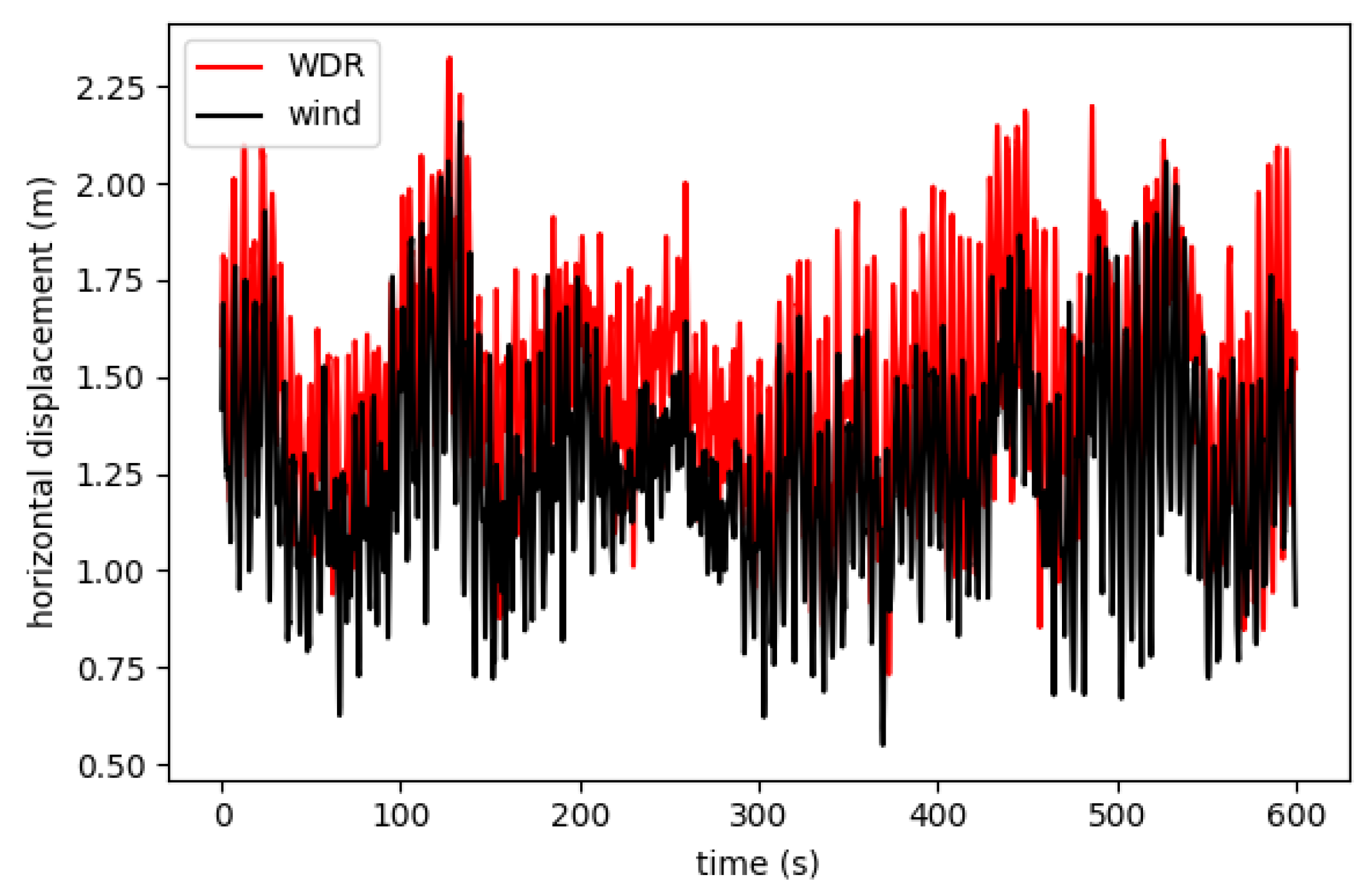
Figure 16 compares the displacements of node 34 subjected to wind loads and WDR loads. The result shows that the WDR loads would produce more significant horizontal displacements than those by wind loads only. The greater WDR load effects could be attributed to the occurrence of the upper rivulet and the impingement of raindrops.
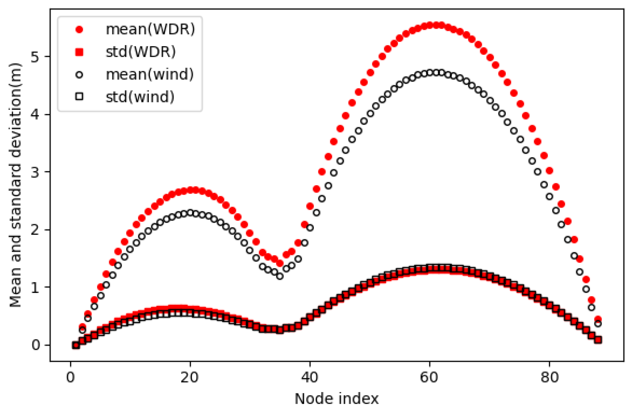
Figure 17 presents the mean and standard deviation of horizontal displacements along the transmission line with node number. It is found that the standard deviation of horizontal displacement shows little difference between two cases of wind loads and WDR loads, while the mean values under the WDR loads are significantly greater than those of wind loads with increase rates around 17%~18%. Such larger swing behavior of the overhead conductor due to WDR loads indicates that it is necessary to take account into the WDR loads in the design of transmission lines for extreme weather conditions of typhoons.
6. Discussion and Conclusions
In this paper, a multi-scale WRF-CFD-FEM numerical framework is developed to analyze the motions of the transmission line subjected to coupled wind and rain loads during typhoon events. A case study was presented in detail by solving the dynamic responses of a full-scale transmission line located in Zhoushan island during Super Typhoon Lekima (2019). The proposed framework firstly reproduced the evolution of super typhoon Lekima, including the wind field and precipitation distribution at the coastal area using mesoscale weather model WRF. Then the coupled wind and rain fields around the transmission line were simulated by the Eulerian multiphase CFD model. Finally, the motion of the conductor under joint actions of wind and rain, i.e., WDR loads, were solved by the finite element method. Some conclusions are summarized as follows:
(1) The ARW model is capable of simulating the track and intensity evolution of typhoon events. It can also explicitly resolve the typhoon wind field and the associated precipitation for a target region. The simulated wind and rain results of Super Typhoon Lekima show good agreements with observations.
(2) The coupled effect of wind and rain load consists of the upper rivulet attached to the conductor surface and the direct impingement of raindrops. The simulated drag and lift coefficients of the overhead conductor under WDR conditions exhibit noticeable variations with the wind angle of attack.
(3) The proposed multiscale WRF-CFD-FEM numerical framework could be used to analyze and predict the dynamic responses of transmission lines under typhoon conditions by considering coupled wind and rain effects. In the case study of Super Typhoon Lekima, the horizontal displacements of the transmission line under the coupling of wind and rain are significantly larger than those of wind loads only. The increasing rates of 17%~18% were found for the mean displacements under WDR loads compared to the wind loads. Such larger swing behavior of the overhead conductor due to WDR loads indicates the importance of coupled effects of wind and rain during typhoon conditions for the design of transmission lines.
Funding
Supports for this research are provided by Ningbo Key R&D Program (Project No. 2023Z221), National Natural Science Foundation of China (Project No. 52178512) and Natural Science Foundation of Zhejiang Province (Project No. LZ22E080006).
Conflicts of Interest
The authors declare no conflict of interest.
References
- Fang, Z.; Wang, Z.; Zhu, R.; Huang, H. Study on Wind-Induced Response of Transmission Tower-Line System under Downburst Wind. Buildings 2022, 12, 891. [Google Scholar] [CrossRef]
- Wang, Z.; Wang, Z. A novel preventive islanding scheme of power system under extreme typhoon events. International Journal of Electrical Power & Energy Systems 2023, 147, 108857. [Google Scholar]
- Jeddi, A.B.; Shafieezadeh, A.; Hur, J.; Ha, J.; Hahm, D.; Kim, M. Multi-hazard typhoon and earthquake collapse fragility models for transmission towers: An active learning reliability approach using gradient boosting classifiers. Earthq. Eng. Struct. Dyn. 2022, 51, 3552–3573. [Google Scholar] [CrossRef]
- Guan, R.; Xiang, C.; Jia, Z. Anti-Wind Experiments and Damage Prediction of Transmission Tower under Typhoon Conditions in Coastal Areas. Energies 2022, 15, 3372. [Google Scholar] [CrossRef]
- Lange, S.; et al. Projecting Exposure to Extreme Climate Impact Events Across Six Event Categories and Three Spatial Scales. Earth’s Future 2020, 8, e2020EF001616. [Google Scholar] [CrossRef]
- Huang, M.; Wang, Q.; Liu, M.; Lin, N.; Wang, Y.; Jing, R.; Sun, J.; Murakami, H.; Lou, W. Increasing typhoon impact and economic losses due to anthropogenic warming in Southeast China. Sci. Rep. 2022, 12, 1–14. [Google Scholar] [CrossRef]
- van der Burgh, A. Hartono Rain-wind-induced vibrations of a simple oscillator. Int. J. Non-linear Mech. 2004, 39, 93–100. [Google Scholar] [CrossRef]
- van der Burgh, A.; Hartono; Abramian, A. A new model for the study of rain-wind-induced vibrations of a simple oscillator. Int. J. Non-linear Mech. 2006, 41, 345–358. [Google Scholar] [CrossRef]
- Deng, H.; Xu, H.; Duan, C.; Jin, X.; Wang, Z. Experimental and numerical study on the responses of a transmission tower to skew incident winds. J. Wind. Eng. Ind. Aerodyn. 2016, 157, 171–188. [Google Scholar] [CrossRef]
- Yang, S.; Hong, H. Nonlinear inelastic responses of transmission tower-line system under downburst wind. Eng. Struct. 2016, 123, 490–500. [Google Scholar] [CrossRef]
- An, L.; Guan, Y.; Zhu, Z.; Wu, J.; Zhang, R. Structural failure analysis of a river-crossing transmission line impacted by the super typhoon Rammasun. Eng. Fail. Anal. 2019, 104, 911–931. [Google Scholar] [CrossRef]
- An, L.; Wu, J.; Zhang, Z.; Zhang, R. Failure analysis of a lattice transmission tower collapse due to the super typhoon Rammasun in July 2014 in Hainan Province, China. J. Wind. Eng. Ind. Aerodyn. 2018, 182, 295–307. [Google Scholar] [CrossRef]
- Yan, B.; Lin, X.; Luo, W.; Chen, Z.; Liu, Z. Numerical Study on Dynamic Swing of Suspension Insulator String in Overhead Transmission Line under Wind Load. IEEE Trans. Power Deliv. 2009, 25, 248–259. [Google Scholar] [CrossRef]
- Zhou, C.; Yin, J.; Liu, Y. Large Swing Behavior of Overhead Transmission Lines under Rain-Load Conditions. Energies 2018, 11, 1092. [Google Scholar] [CrossRef]
- Fu, X.; Li, H.-N. Dynamic analysis of transmission tower-line system subjected to wind and rain loads. J. Wind. Eng. Ind. Aerodyn. 2016, 157, 95–103. [Google Scholar] [CrossRef]
- Fu, X.; Li, H.-N. Effect of Raindrop Size Distribution on Rain Load and Its Mechanism in Analysis of Transmission Towers. Int. J. Struct. Stab. Dyn. 2018, 18. [Google Scholar] [CrossRef]
- Zhou, C.; Liu, Y.; Ma, Z. Investigation on aerodynamic instability of high-voltage transmission lines under rain-wind condition. J. Mech. Sci. Technol. 2015, 29, 131–139. [Google Scholar] [CrossRef]
- Zhou, C.; Yin, J.; Liu, Y. Effects of wind and rain on the motion of the high-voltage conductor in a simplified valley terrain. Electr. Power Syst. Res. 2019, 173, 153–163. [Google Scholar] [CrossRef]
- Bauer, P.; Thorpe, A.; Brunet, G. The quiet revolution of numerical weather prediction. Nature 2015, 525, 47–55. [Google Scholar] [CrossRef]
- Yeh, K.-S.; Zhang, X.; Gopalakrishnan, S.; Aberson, S.; Rogers, R.; Marks, F.; Atlas, R. Performance of the experimental HWRF in the 2008 Hurricane Season. Nat. Hazards 2011, 63, 1439–1449. [Google Scholar] [CrossRef]
- Huang, M.; Wang, Y.; Lou, W.; Cao, S. Multi-scale simulation of time-varying wind fields for Hangzhou Jiubao Bridge during Typhoon Chan-hom. J. Wind. Eng. Ind. Aerodyn. 2018, 179, 419–437. [Google Scholar] [CrossRef]
- Xu, H.; Zhao, D.; Yin, J.; Duan, Y.; Gao, W.; Li, Y.; Zhou, L. Indirect Effects of Binary Typhoons on an Extreme Rainfall Event in Henan Province, China From 19 to 21 July 2021. 3. Sensitivities to Microphysics Schemes. J. Geophys. Res. Atmos. 2023, 128. [Google Scholar] [CrossRef]
- Park, J.; Moon, J.; Cho, W.; Cha, D.; Lee, M.; Chang, E.; Kim, J.; Park, S.; An, J. Sensitivity of Real-Time Forecast for Typhoons Around Korea to Cumulus and Cloud Microphysics Schemes. J. Geophys. Res. Atmos. 2023, 128. [Google Scholar] [CrossRef]
- Wang, M.; Zhao, K.; Pan, Y.; Xue, M. Evaluation of Simulated Drop Size Distributions and Microphysical Processes Using Polarimetric Radar Observations for Landfalling Typhoon Matmo (2014). J. Geophys. Res. Atmos. 2020, 125. [Google Scholar] [CrossRef]
- Blocken, B.; Carmeliet, J. A review of wind-driven rain research in building science. Journal of Wind Engineering and Industrial Aerodynamics 2004, 92, 1079–1130. [Google Scholar] [CrossRef]
- Ge, H.; Deb Nath, U.K.; Chiu, V. Field measurements of wind-driven rain on mid-and high-rise buildings in three Canadian regions. Build. Environ. 2017, 116, 228–245. [Google Scholar] [CrossRef]
- Kubilay, A.; Derome, D.; Blocken, B.; Carmeliet, J. High-resolution field measurements of wind-driven rain on an array of low-rise cubic buildings. J. Affect. Disord. 2014, 78, 1–13. [Google Scholar] [CrossRef]
- Blocken, B.; Dezsö, G.; van Beeck, J.; Carmeliet, J. Comparison of calculation models for wind-driven rain deposition on building facades. Atmospheric Environ. 2010, 44, 1714–1725. [Google Scholar] [CrossRef]
- Ge, H.; Chiu, V.; Stathopoulos, T.; Souri, F. Improved assessment of wind-driven rain on building façade based on ISO standard with high-resolution on-site weather data. J. Wind. Eng. Ind. Aerodyn. 2018, 176, 183–196. [Google Scholar] [CrossRef]
- Huang, S.; Li, Q. Numerical simulations of wind-driven rain on building envelopes based on Eulerian multiphase model. J. Wind. Eng. Ind. Aerodyn. 2010, 98, 843–857. [Google Scholar] [CrossRef]
- Kubilay, A.; Derome, D.; Blocken, B.; Carmeliet, J. Numerical simulations of wind-driven rain on an array of low-rise cubic buildings and validation by field measurements. J. Affect. Disord. 2014, 81, 283–295. [Google Scholar] [CrossRef]
- Wang, X.; Li, Q.; Li, J. Field measurements and numerical simulations of wind-driven rain on a low-rise building during typhoons. J. Wind. Eng. Ind. Aerodyn. 2020, 204, 104274. [Google Scholar] [CrossRef]
- Kubilay, A.; Derome, D.; Blocken, B.; Carmeliet, J. CFD simulation and validation of wind-driven rain on a building facade with an Eulerian multiphase model. J. Affect. Disord. 2012, 61, 69–81. [Google Scholar] [CrossRef]
- Kubilay, A.; Derome, D.; Blocken, B.; Carmeliet, J. Wind-driven rain on two parallel wide buildings: Field measurements and CFD simulations. J. Wind. Eng. Ind. Aerodyn. 2015, 146, 11–28. [Google Scholar] [CrossRef]
- Skamarock, W.C.; Klemp, J.B. A time-split nonhydrostatic atmospheric model for weather research and forecasting applications. J. Comput. Phys. 2008, 227, 3465–3485. [Google Scholar] [CrossRef]
- Laprise, R. The Euler Equations of Motion with Hydrostatic Pressure as an Independent Variable. Mon. Weather. Rev. 1992, 120, 197–207. [Google Scholar] [CrossRef]
- Lim, K.-S.S.; Hong, S.-Y. Development of an Effective Double-Moment Cloud Microphysics Scheme with Prognostic Cloud Condensation Nuclei (CCN) for Weather and Climate Models. Mon. Weather. Rev. 2010, 138, 1587–1612. [Google Scholar] [CrossRef]
- Locatelli, J.D.; Hobbs, P.V. Fall speeds and masses of solid precipitation particles. J. Geophys. Res. 1974, 79, 2185–2197. [Google Scholar] [CrossRef]
- Mätzler, C. Drop-Size Distributions and Mie Computations for Rain; Institute of Applied Physics, University of Bern: Bern, Switzerland, 2002. [Google Scholar]
- Hikami, Y.; Shiraishi, N. Rain-wind induced vibrations of cables stayed bridges. Journal of Wind Engineering and Industrial Aerodynamics 1988, 29, 409–418. [Google Scholar] [CrossRef]
- Ying, M.; Zhang, W.; Yu, H.; Lu, X.; Feng, J.; Fan, Y.; Zhu, Y.; Chen, D. An Overview of the China Meteorological Administration Tropical Cyclone Database. J. Atmos. Ocean. Technol. 2014, 31, 287–301. [Google Scholar] [CrossRef]
- Lu, X.; Yu, H.; Ying, M.; Zhao, B.; Zhang, S.; Lin, L.; Bai, L.; Wan, R. Western North Pacific Tropical Cyclone Database Created by the China Meteorological Administration. Adv. Atmospheric Sci. 2021, 38, 690–699. [Google Scholar] [CrossRef]
- de Wolf, D.A. On the Laws-Parsons distribution of raindrop sizes. Radio Science 2001, 36, 639–642. [Google Scholar] [CrossRef]
- Huang, S.; Li, Q.; Liu, M.; Chen, F.; Liu, S. Numerical Simulation of Wind-Driven Rain on a Long-Span Bridge. Int. J. Struct. Stab. Dyn. 2019, 19. [Google Scholar] [CrossRef]
- Shinozuka, M.; Deodatis, G. Simulation of Stochastic Processes by Spectral Representation. Appl. Mech. Rev. 1991, 44, 191–204. [Google Scholar] [CrossRef]
|
Disclaimer/Publisher’s Note: The statements, opinions and data contained in all publications are solely those of the individual author(s) and contributor(s) and not of MDPI and/or the editor(s). MDPI and/or the editor(s) disclaim responsibility for any injury to people or property resulting from any ideas, methods, instructions or products referred to in the content. |
© 2024 by the authors. Licensee MDPI, Basel, Switzerland. This article is an open access article distributed under the terms and conditions of the Creative Commons Attribution (CC BY) license (http://creativecommons.org/licenses/by/4.0/).
