1. Introduction
This paper studies different techniques to improve the axial stiffness of a known horizontal axis high-temperature superconducting (HTS) zero-field cooled (ZFC) horizontal axis radial levitation bearing. The enhancement of axial stiffness is tested by passively adding limiting permanent magnet (PM) rings aligned with the PM rotor and independent from the PM rotor at a specific distance from the side rotor PM rings. With this new not significant cost addition, the modified bearing may compete in terms of guiding stability with field-cooled (FC) superconducting magnetic bearings (SMB) for high-precision axial stability applications such as precision gyroscopes, horizontal axis propellers, and turbines. The focus of adopting ZFC instead of FC is to get higher impulsion and levitation forces, allowing an increase in the gap and safety distance [
1,
2] and reducing the magnetic field penetration and electromagnetics losses in HTS bulks, increasing efficiency [
3,
4] and extending their lifetime [
5,
6].
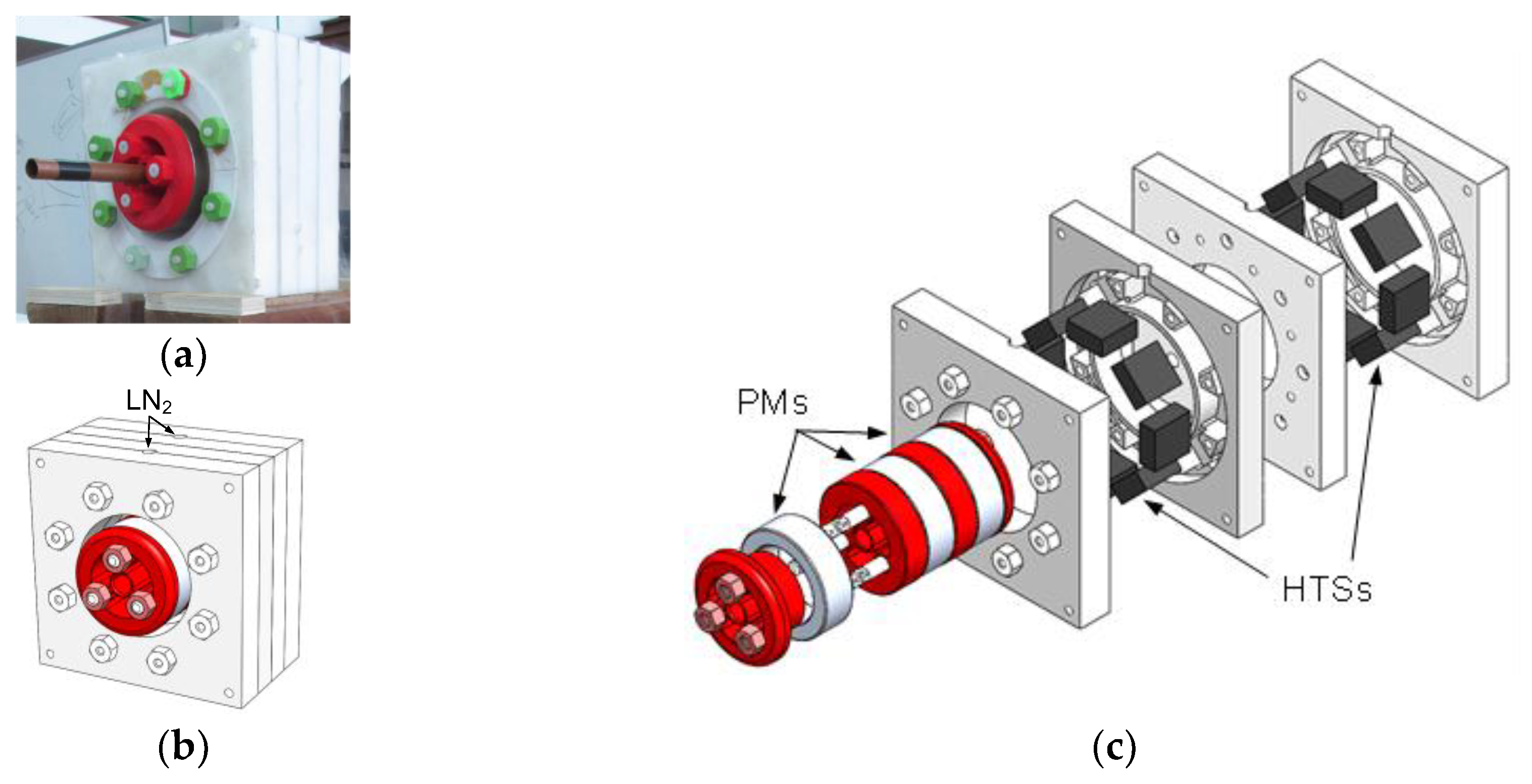
Figure 1(a) and
Figure 1(b) show respectively a photo and the 3D design of the known HTS ZFC bearing experimental prototype assembly.
Figure 1(c) shows the 3D design of the experimental prototype extrusion.
The studied passive bearing geometry includes a stator housing two discontinuous rings of HTS bulks cryocooled using ZFC, and a PM rotor including three radially magnetized PM rings disposed in an alternate polarization arrangement. Each discontinuous ring of HTS bulks in the stator could contain a maximum of eight HTS bulks. The polarization of the intermediate PM ring is opposite from the polarizations of the two side PM rings, existing attraction between adjacent PM rings in the rotor [
7].
The initial prediction of magnetic levitation and guidance forces and measurement of rotor dynamics were performed in [
7]. Studies on the LN2 consumption and YBCO bulk temperature evolution for different thermal processes in the initial ZFC and the operation of the experimental bearing prototype were presented [
8,
9]. A methodology was developed to predict the released thermal power evolution from the measured LN2 mass loss rate used to determine the autonomous safety service time of the studied horizontal HTS ZFC levitating bearing [
10]. Initial optimization of the bearing geometry volume and cost with maximization of levitation forces was performed [
11]. Additional optimization of the PM ring and HTS bulk ring spacings was done to maximize the bearing guiding stability [
12].
A method to measure the stiffness of a repulsive PMB in single gimbal magnetically suspended control moment gyroscope was proposed [
13]. A model was developed to determine the magnetic stiffness in radial flux permanent magnet generators of direct-drive wind turbines from the structural mechanical stiffness depending on the verified operation deflection [
14]. An axial flux high-temperature superconducting (HTS) motor for aircraft propulsion was designed and analyzed [
15]. Magnetic forces and stiffness for an axial flux machine using passive magnetic bearing with axial magnetization were analyzed on wind and hydro low-speed turbines [
16]. The modeling of the axial magnetic force and stiffness of a ring-shaped PM passive vibration isolator was presented [
17]. The modeling of electromagnetic (EM) force and axial-stiffness for an EM negative-stiffness spring toward vibration isolation was presented [
18]. The magnetic forces and axial-stiffness were analyzed for a new axial-type superconducting magnetic bearing (SMB) based on the interaction behavior between a PM and two closed superconducting coils [
19].
A comparison of the axial stiffness of journal bearings in FC and ZFC cooling modes was made [
20]. This paper aims to evaluate ways to passively augment the axial stiffness of studied horizontal axis HTS ZFC radial levitation bearing so that it may compete in terms of guiding stability with FC superconducting bearings.
Section 2 focuses on presenting designs and materials for the existing and modified bearing geometries and describing the adopted analysis methods to reduce numerical processing.
Section 3 presents result on determining and validating the equivalent magnetic permeability when the rotor and stator axes are aligned. Also, on the evaluation of the axial stiffness augmentation with the addition of HTS bulks in the stator or limiting PM rings aligned with the rotor. Results are discussed in
Section 4 and the main conclusions stated in
Section 5.
2. Materials and Methods
This section presents and describes the designs, materials, and analysis methods considered in the studies.
2.1. Designs and Materials
The considered HTS ZFC horizontal axis radial levitation Passive Magnetic Bearing (PMB) topology includes a stator housing two discontinuous rings, each one with up to eight High-Temperature Superconductor (HTS) bulks, and a Permanent Magnet (PM) rotor with three radially magnetized continuous PM rings, the polarization of the intermediate one opposite from the side PM rings. Each discontinuous ring of HTS bulks in the zone between the middle PM ring and one side PM ring. HTS bulks of Yttrium Barium Copper Oxide (YBCO) and PM rings of Neodymium Iron Borum (NdFeB) with grade N40 have been used in experimental prototypes and considered for 3D Finite Element Analysis (FEA).
Guiding optimization studies were performed [
12] considering both bulks of dimensions
and
. The results have shown that besides the first ones generate guidance forces slightly higher, with the second ones the magnetic levitation is higher. For this reason and because of the availability of good condition bulks of dimensions
in our laboratory, only this bulk size is considered in the studies presented in this document.
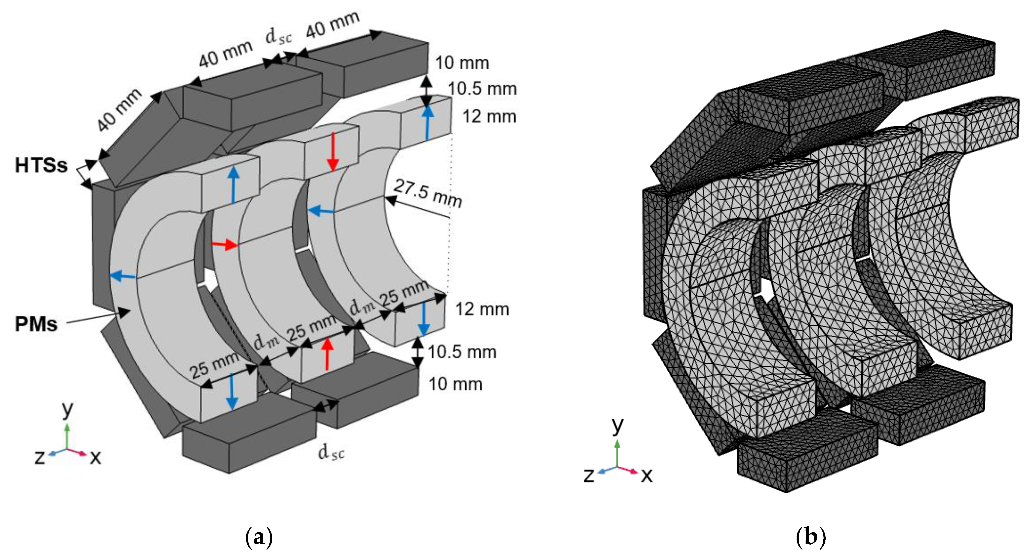
Figure 2(a) and
Figure 2(b) show the dimensioned longitudinal bisection design of the studied bearing topology and corresponding mesh grid for 3D FEA. Variables
and
refer to the distances respectively between the two discontinuous rings of HTS bulks in the stator and between adjacent PM rings in the rotor.
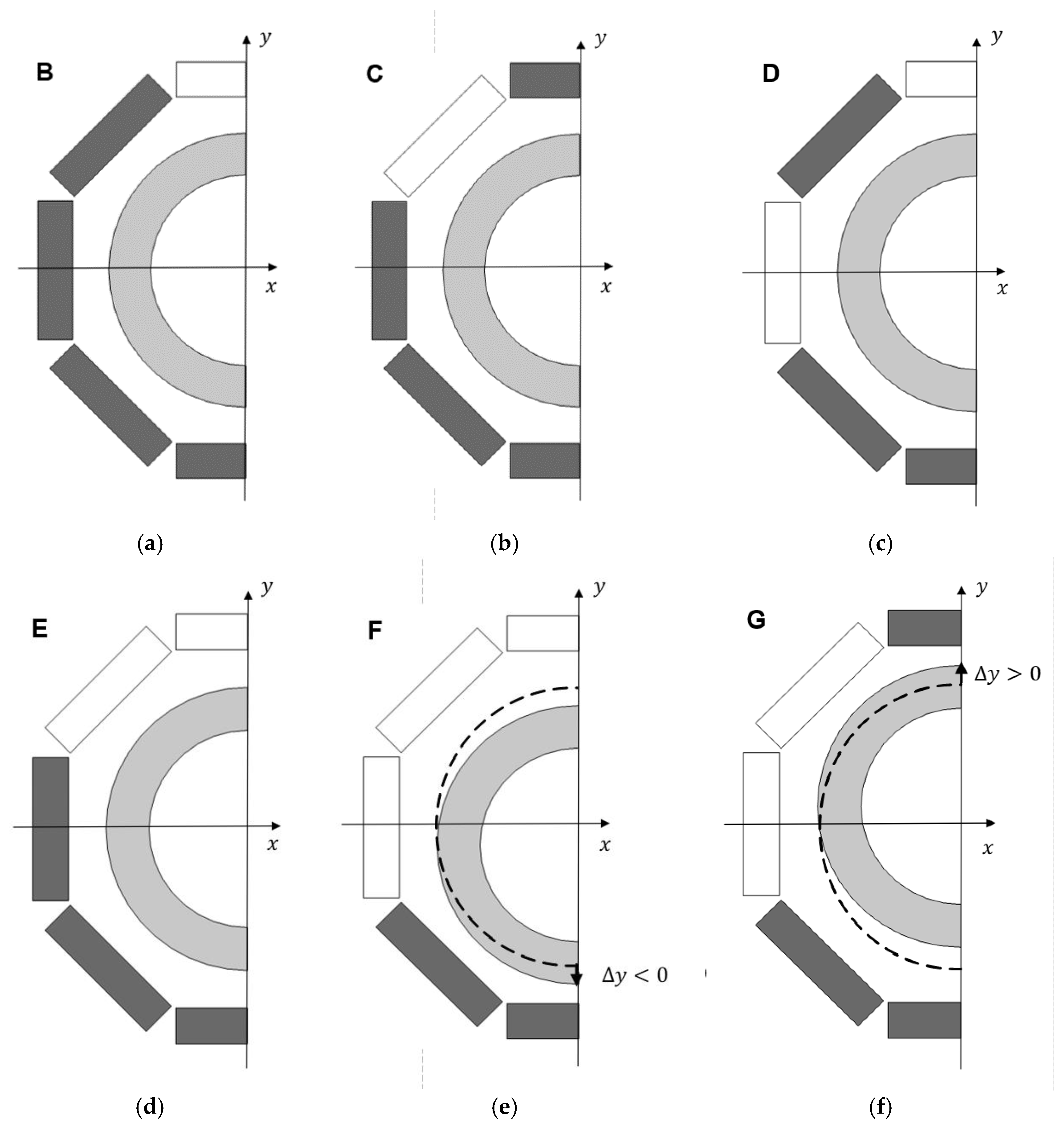
To facilitate the process of ZFC, after the ZFC of HTS bulks, the rotor was always placed in the stator cavity with the rotor and stator axes aligned. Thus, by completing the stator with a total of sixteen HTS bulks, referred as to Topology A, it would be impossible to levitate with the rotor axis at the center position. With this topology of HTS bulks, distributed symmetrically in the stator, the resulting magnetic levitation force in the direction would be zero, and gravity pulls the rotor down forcing it to levitate with eccentricity.
Figure 3(a) to
Figure 3(f) show different possible topologies of asymmetric distribution of HTS bulks in the stator.
Figure 3(e) and
Figure 3(f) show respectively Topology F with a negative vertical deviation of the rotor (
) and Topology G with a positive vertical deviation of the rotor (
). The dashed lines refer to the rotor position at
, with the rotor and stator axes aligned.
Topology F with only six HTS bulks at the stator bottom, maximizes the resulting magnetic force in the y direction, referred to as levitation force, with less investment on HTS bulks. Because this topology enables a wider range of vertical deviations where levitation is verified, it was considered in previous studies for the validation by experimental testing of magnetic forces predicted by numerical FEA. On the other hand, the verified magnetic guidance forces are minimal with Topology F, because the higher the magnetic energy portion used for levitation, the lower the magnetic energy portion used for guidance.
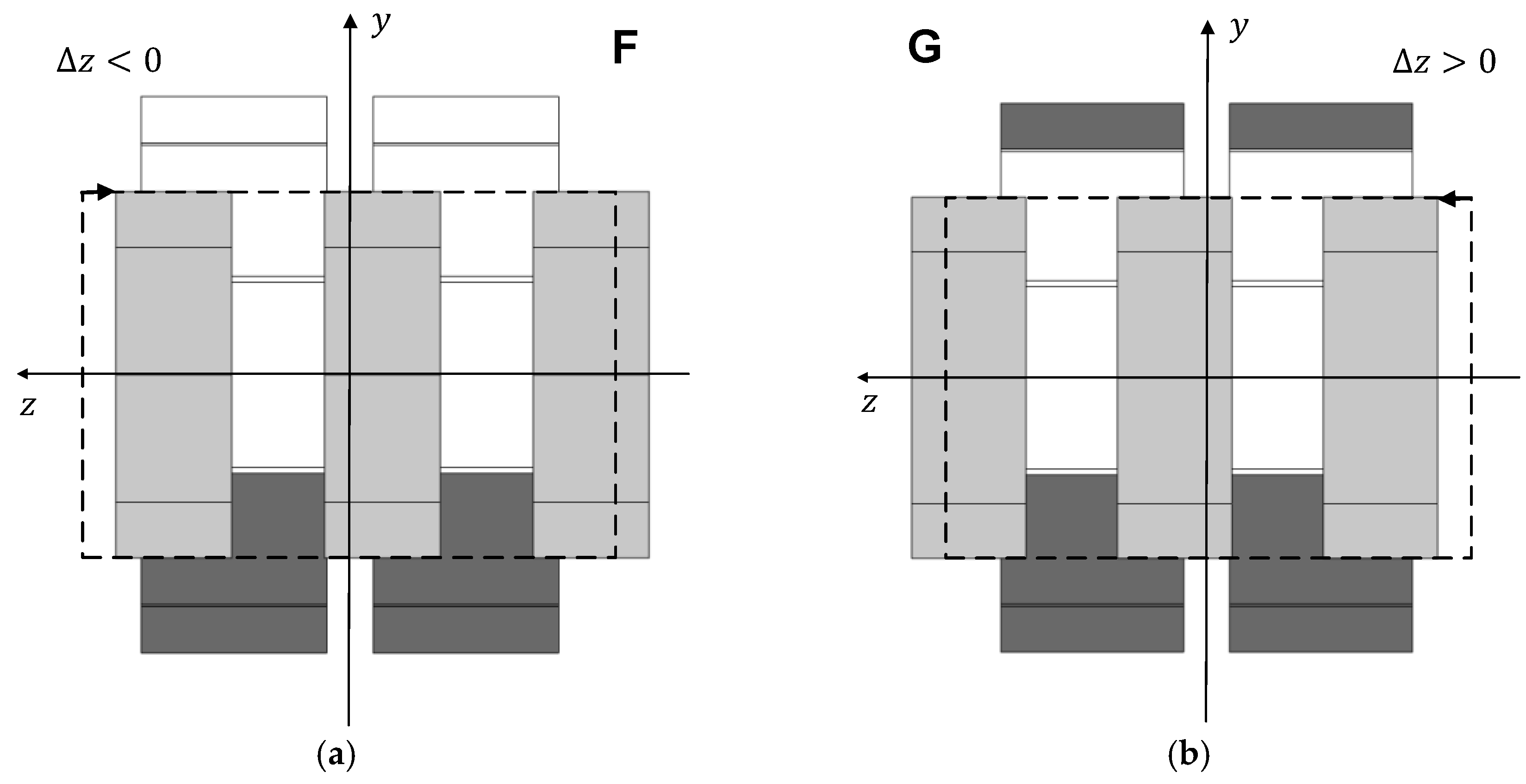
Figure 4(a) and
Figure 4(b) show views of longitudinal bisections respectively for Topology F with a negative axial deviation of the rotor (
) and for Topology G with a positive axial deviation of the rotor (
). The dashed lines refer to the rotor position at
.
in (a) and for Topology G with a positive axial deviation of the rotor in (b).
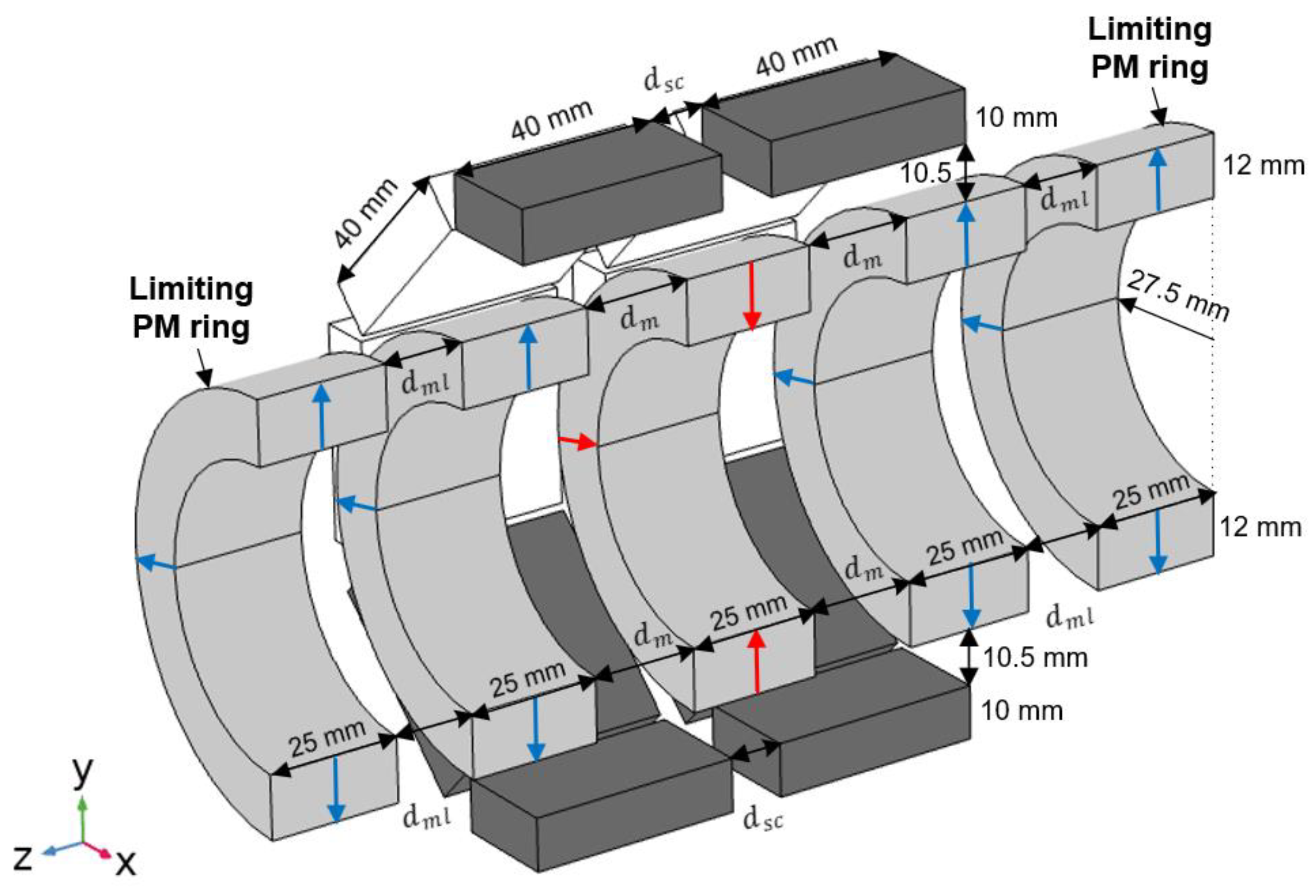
Figure 5 shows the design of the proposed change in adding two limiting radially magnetized PM rings with the same polarization as the rotor edge PM rings, to significantly increase the axial stiffness with no significant additional investment. Variable
represents the distance between the rotor edge PM rings and the limiting PM rings, with no axial deviation of the rotor (
).
2.2. Adopted Method to Reduce Numerical Processing in the Prediction of Magnetic Guidance Forces
The required numerical processing in 3D FEA prediction of magnetic forces could be significantly reduced if a simplified model of equivalent permeability is considered for HTS bulks [
11,
21]. This approach avoids performing a complete electromagnetic analysis using non-linear conductivity power laws and the Kim-Anderson model for type II superconductors to determine the detailed current distributions and magnetization of HTS bulks. [
22,
23], while providing accurate results if an appropriate magnetic permeability is considered.
Previous results [
11,
12] have shown that for the considered ZFC radial bearing, the equivalent permeability of HTS bulks varies with the rotor vertical deviation. Their equivalent permeability does not notably vary on the limited range of possible rotor axial deviations when kept with no radial deviation. Once the prediction and validation of magnetic guidance forces are performed keeping the rotor and stator axes coincident (with no radial deviation of the rotor), the FEA numerical prediction of magnetic guidance forces is determined assuming the approximate value of equivalent magnetic permeability for the HTS bulks verified when there is no rotor radial deviation. Results related to the determination and validation of such equivalent magnetic permeability values are presented in subsection 3.1.
3. Results
This section first presents results of determining and validating the HTS bulks’ equivalent magnetic permeability with no rotor radial deviation. Then, results on the axial stiffness depending on the considered topology and number of HTS bulks in the stator are presented. At the end, results concerning the determination and validation of the axial stiffness augmentation by adding limiting PM rings with the same polarization as the rotor edge PM rings, are presented.
3.1. Equivalent Magnetic Permeability for HTS Bulks with no Radial Deviation of the PM Rotor
The validation of the HTS bulks’ equivalent permeability with no radial deviation of the PM rotor was performed considering Topology F because this topology maximizes the range of rotor vertical deviations where levitation is verified. Also, with this topology, the number of HTS bulks is only six, minimizing the required numerical processing. The six HTS bulks are located on the lower half of the stator, being enough to determine and validate the variation of the HTS bulks’ magnetic permeability with the rotor vertical deviation considering that the bearing geometry presents symmetry with relation to the horizontal plane of longitudinal bisection.
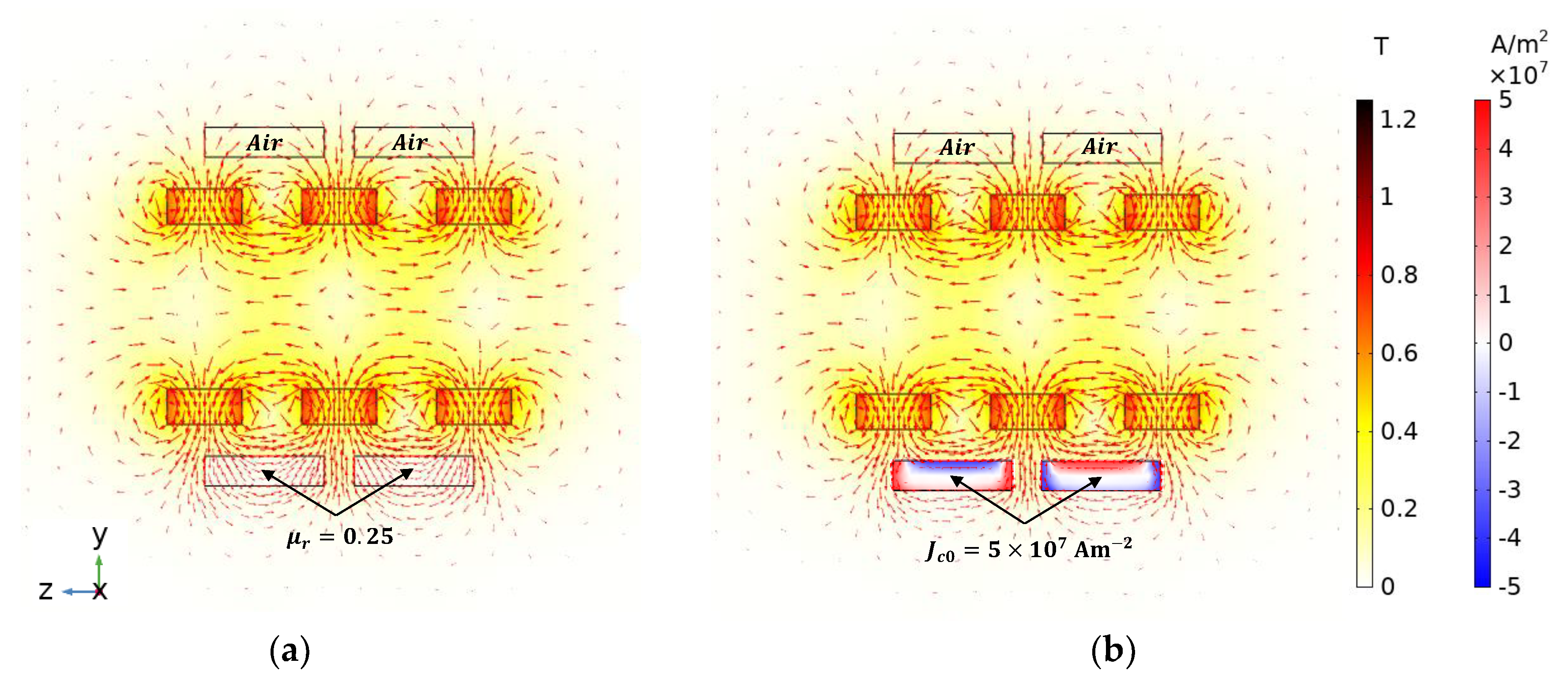
Figure 6(a) shows the distribution of magnetic field density
resultant from 3D FEA simulations with no radial deviation of the PM rotor considering HTS bulks with equivalent magnetic permeability
.
Figure 6(b) shows the distributions of
and detailed current density
obtained considering the complete electromagnetic non-linear power-law model for the conductivity of type II superconductors with
. The obtained distribution of
nearby HTS bulk boundaries is similar with the two models.
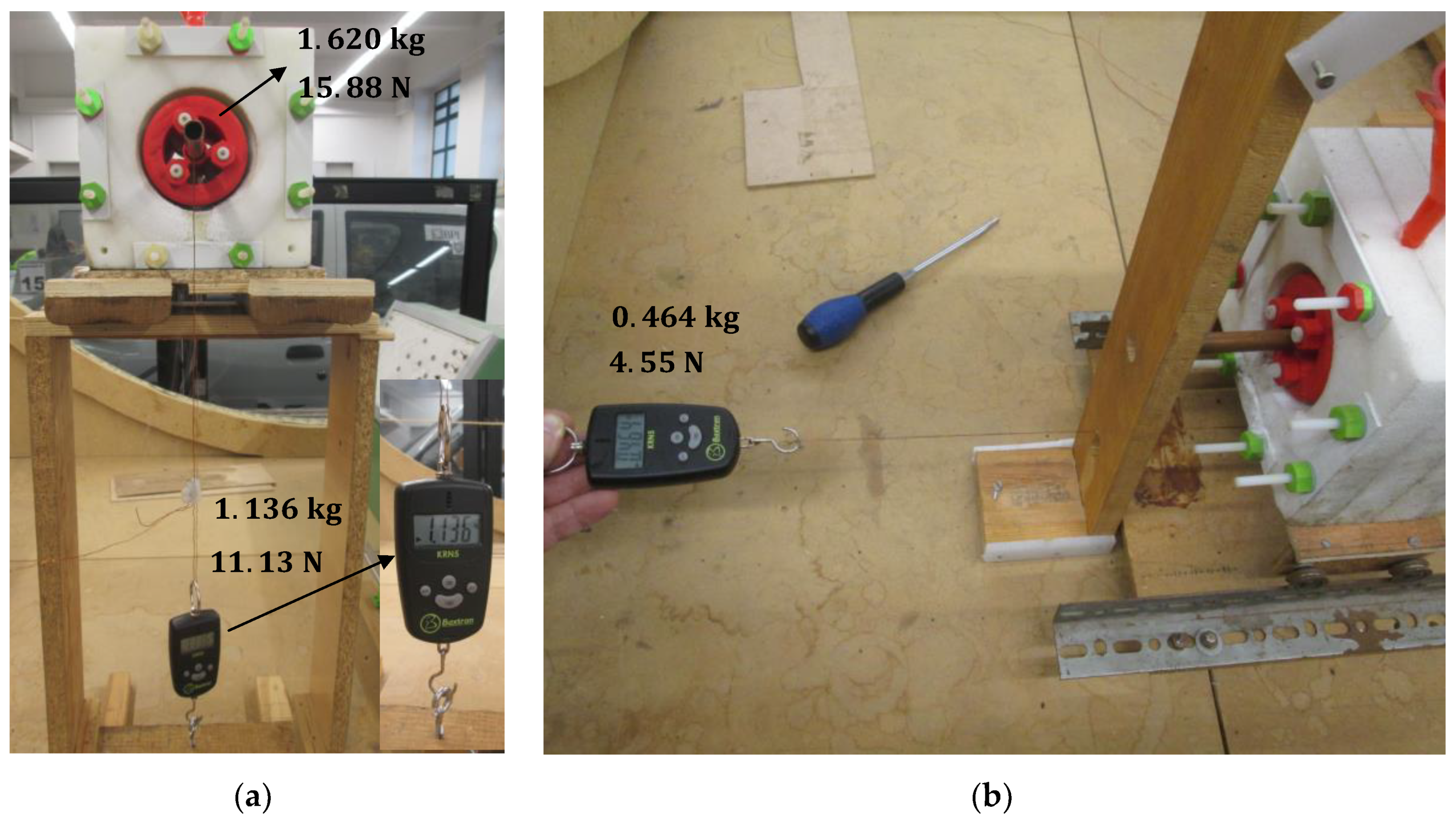
Figure 7(a) shows the experimental measurement of the magnetic levitation force
with no vertical deviation
) and no axial deviation
) of rotor D20
). The measured levitation force magnitude
, is the sum of the rotor gravity
with the impulsion force measured with Baxtran KRN05 dynamometer
Figure 7(b) shows the experimental measurement of the magnetic guidance force
with no vertical deviation
) and an axial deviation
of rotor D20 where the predicted guidance force is maximum. The measured guidance force with
and
was
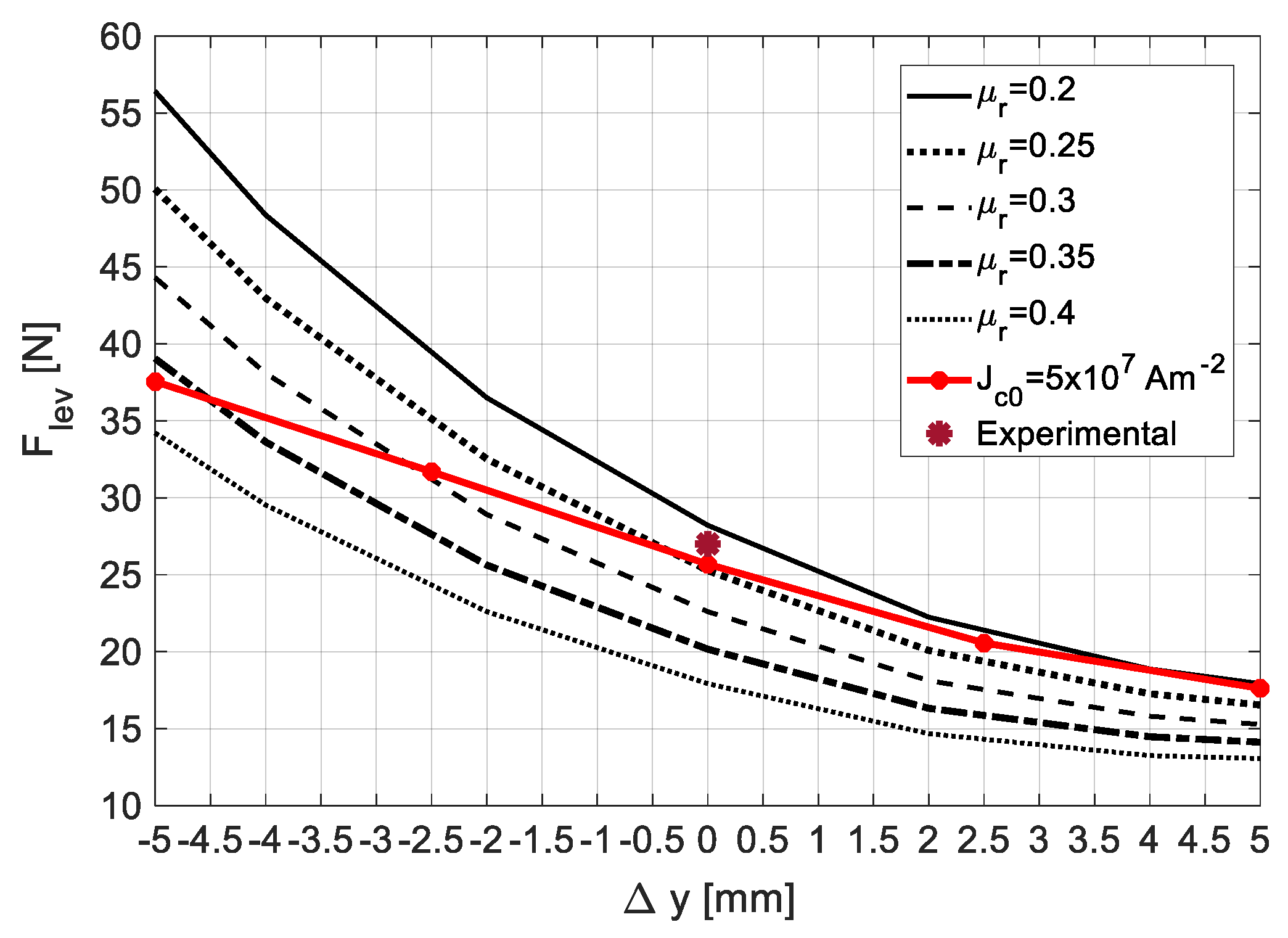
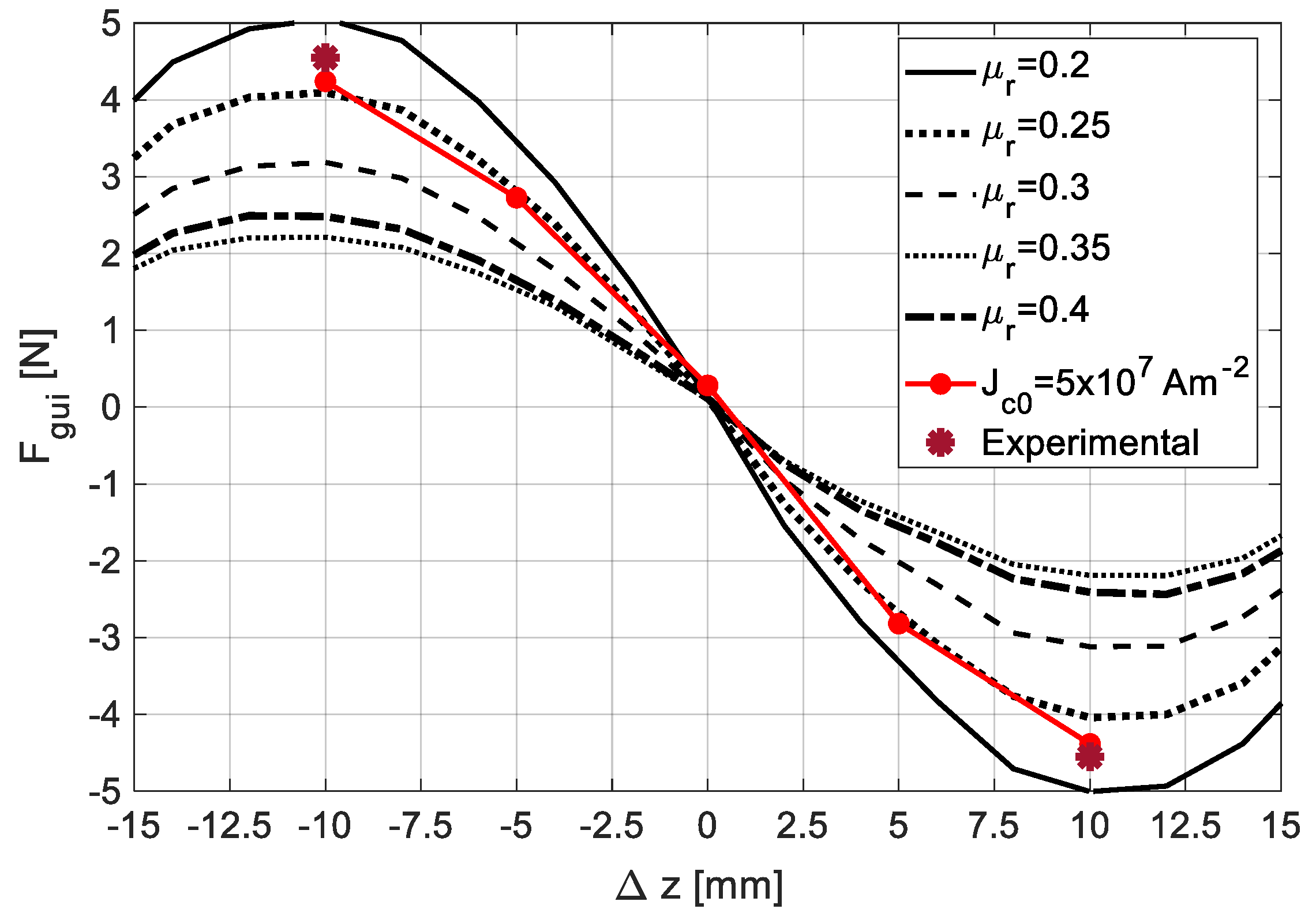
Figure 8 shows the characteristics
with
, predicted by 3D FEA simulations. Five were obtained considering equivalent values of
ranging from
to
, and one (red line) obtained using the complete electromagnetic model with
.
According to [
11,
12] the characteristic
with
, resultant from experimental measurements using rotor D20 (
= 20 mm), follows in between the two ones predicted by 3D FEA simulations using the complete electromagnetic model with
and
. The characteristic obtained considering
crosses the one obtained with the complete model considering
, at almost
(no vertical deviation of the rotor). Also, the experimental measurement of the levitation force at
(
is close to the predicted one at the point close to
where the two characteristics for
and
cross each other.
Figure 9 shows the characteristics
with
, predicted by 3D FEA simulations. Five were obtained considering equivalent values of
ranging from
to
, and one (red line) obtained using the complete electromagnetic model with
. The experimental measurement of the guidance force at
(
) is close to the predicted ones considering
and
.
From the obtained results one may conclude that keeping the rotor and stator axes coincident (no rotor vertical deviation ), the verified equivalent magnetic permeability remains almost constant for values of axial deviation ranging from to , assuming a value close to .
3.2. Axial Stiffness Augmentation by Adding HTS Bulks to the Stator
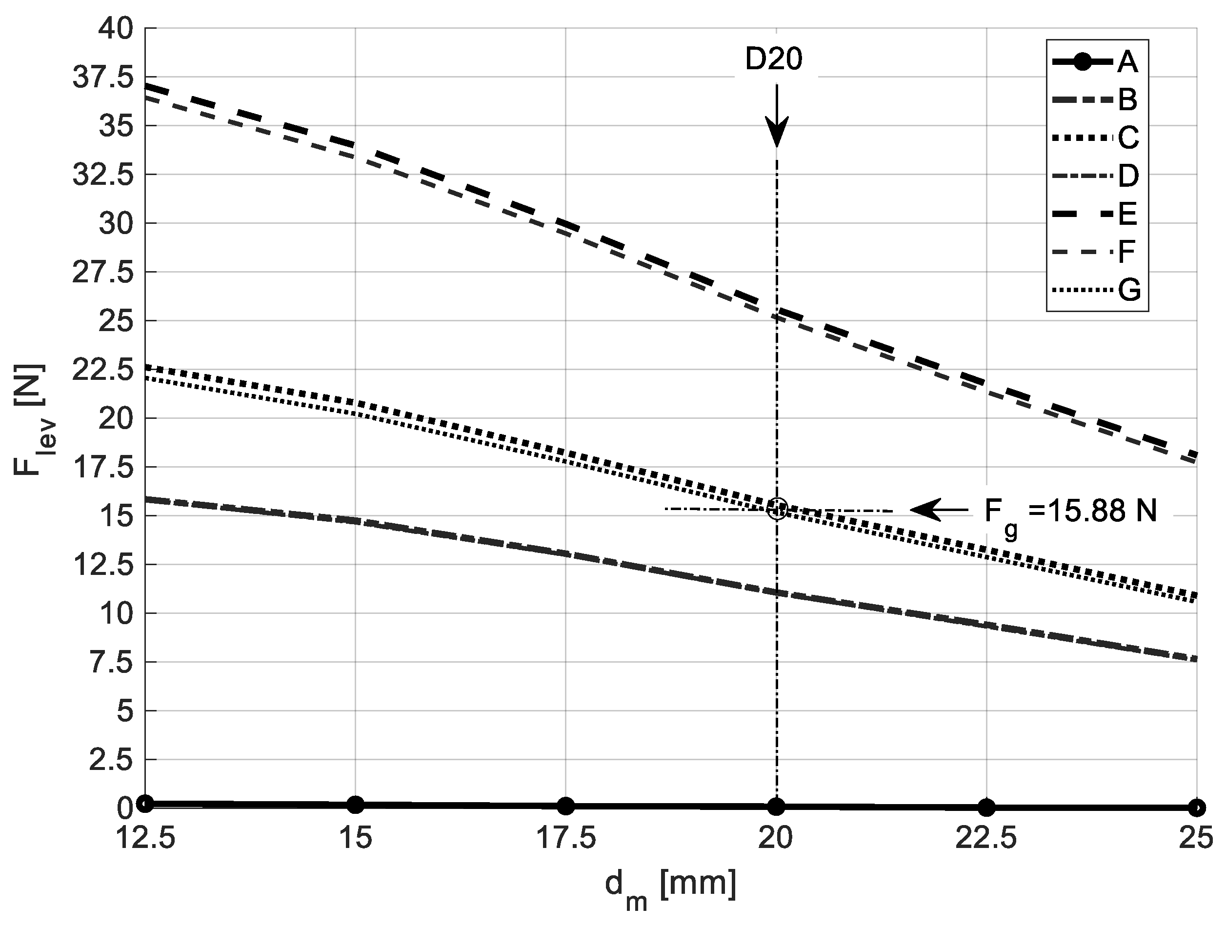
Figure 10 shows the dependence of
with the distance
between adjacent PM rings in the rotor
obtained by 3D FEA considering the HTS bulks with an equivalent magnetic permeability
, for the several topologies of HTS bulks in the stator. This is done, keeping the rotor at the axial equilibrium position (
) with its axis coinciding with the stator axis (
).
The levitation force decreases with the increase of the distance between adjacent PM rings in the rotor. The generated levitation assumes higher values with topologies E and F. The values of for these two topologies are close because the HTS Bulks with higher surfaces disposed vertically in Topology E almost do not contribute to levitation. The investment with Topology E including ten HTS bulks is higher than with topology F including six HTS bulks, but Topology E guarantees higher stiffness in the direction. A similar thinking could be done by comparing topologies C and G. Thus, the investment with Topology C is higher than with Topology G, but Topology C guarantees higher stiffness in the direction. With topologies C and G, it is possible to keep rotor D20 () levitating with a vertical deviation close to , because its gravity force is .
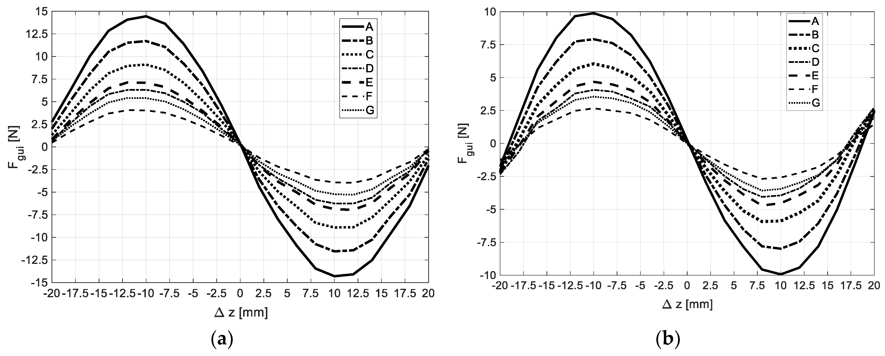
Figure 11(a) and
Figure 11(b) show respectively for rotors with
and
, the dependence of the guidance
with the rotor axial deviation
keeping its axis coinciding with the stator axis (
, obtained by 3D FEA considering an equivalent relative magnetic permeability
. This dependence was predicted for the several topologies of HTS bulks in the stator.
The guidance force
is higher with
than with
This force depends on the number of HTS bulks in the stator, increasing with the number of HTS bulks of the considered topology.
Table 1 states the axial stiffness
with rotor D20 (
) within
, for several topologies of HTS bulks in the stator that allow the rotor levitation with positive vertical deviation
) according to
Figure 10.
Topology F was considered in previous studies for the reasons explained in subsections 2.1 and 3.1. When moving from Topology F to topologies G, E, or G there will be a significant investment in the number of additional HTS bulks needed. The axial stiffness with Topology C is still low, making the studied horizontal axis HTS ZFC radial levitation PMB inappropriate for applications requiring high-precision axial stability.
3.3. Axial Stiffness Augmentation by Adding Limiting PM Rings
The axial stiffness does not increase significantly when HTS bulks are added to the stator. The addition of two limiting PM rings radially magnetized with the same polarization as the rotor edge PM rings to significantly increase the axial stiffness of the studied PMB is evaluated here.
Figure 12 shows the experimental setup to measure the magnetic impulsion force
between the limiting PM ring on one side and the closest rotor edge PM ring depending on distance
.
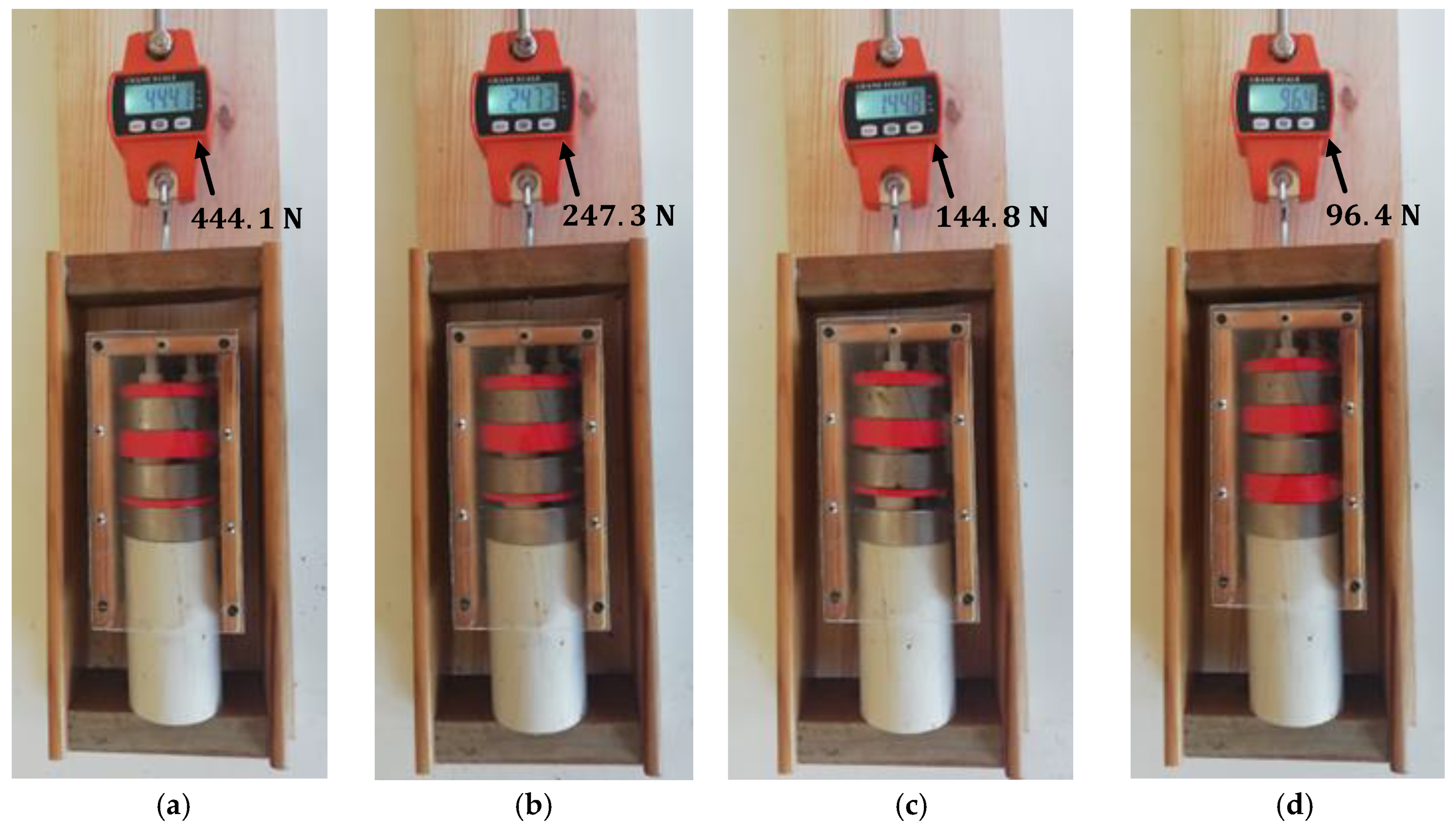
Figure 13 shows measurements of
for distances
equal to: a)
, b)
, c)
, and d)
.
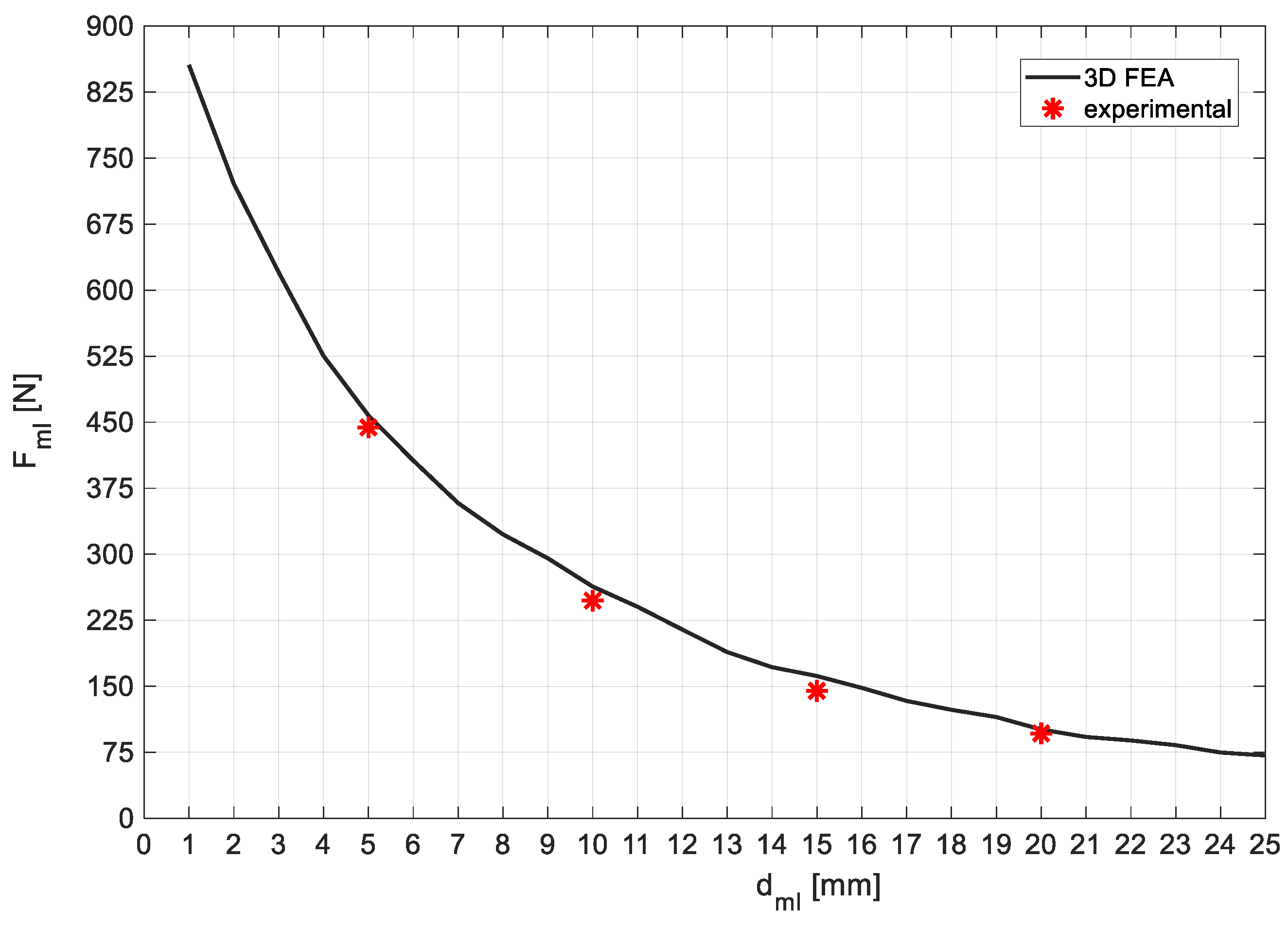
Figure 14 shows the characteristics of the magnetic impulsion force
between the limiting PM ring on one side and the closest rotor edge PM ring depending on distance
, predicted by 3D FEA and obtained experimentally. The experimental measurements follow with good approximation the characteristic predicted by 3D FEA.
The total guidance force
of the modified horizontal axis HTS ZFC passive bearing including limiting PMs results from the sum of the basic bearing guidance force
with the additional guidance force
from the limiting PM rings impulsion action, as expressed by equation (1):
Dividing both members of equation (1) by
results that the total guiding stiffness
of the modified horizontal axis HTS ZFC passive bearing including limiting PMs results from the sum of the basic bearing guiding stiffness
with the additional guiding stiffness
from limiting PMs impulsion action. This can be modelled by a spring that results from the parallel of two springs.
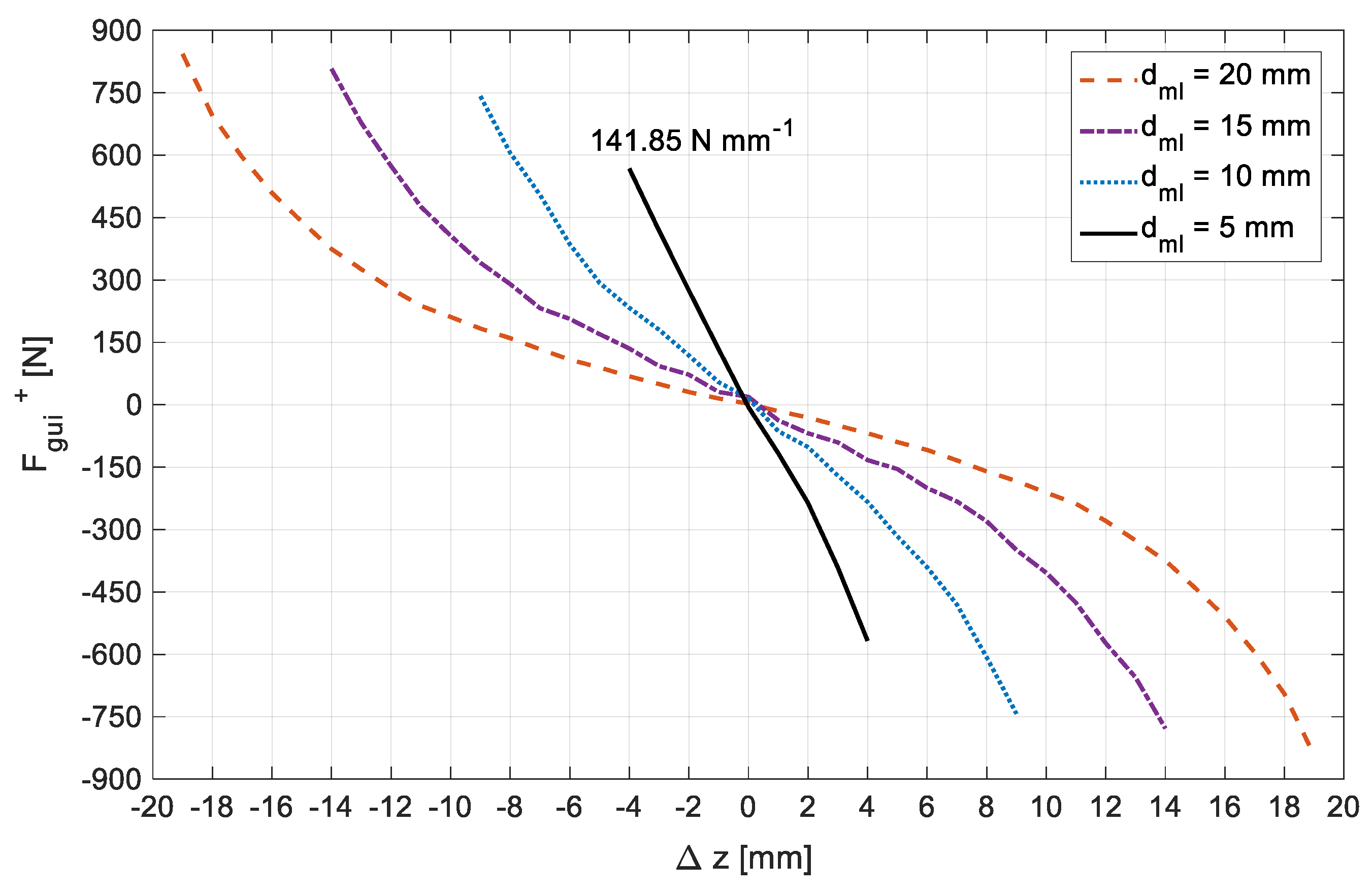
Figure 15 shows the characteristics of the total guidance force
as a function of the axial deviation
for distances
equal to
,
,
and
. These characteristics were predicted by 3D FEA considering the use of rotor D20 (
) and the HTS bulks with an equivalent relative permeability
distributed in the stator according to Topology G.
With limiting PM rings placed at a distance
from the rotor edge PM rings, limiting the rotor axial deviation to
, the total predicted axial stiffness would be
. This value is significantly higher (more than one hundred times) than the one presented in
Table 1 for topology G without limiting PM rings.
4. Discussion
With addition of HTS bulks in the stator, magnetic guidance forces increase but on the other hand magnetic levitation forces decrease. Topology F with only six HTS bulks at the bottom of the stator, is the one that guarantees higher levitation but on the other hand is the more unstable topology. Because Topology F enables a wider range of vertical deviations for testing, this topology was used on the prediction and evaluation of the HTS bulks’ equivalent relative permeability as a function of the rotor vertical deviation.
According to
Figure 10, with topologies C, E, F, and G of HTS bulks in the stator, the PM rotor D20 can levitate at vertical deviations
. When moving from Topology F to Topology E, the levitation remains the same, but the guidance force increases about
. Topologies C and G provide almost equal levitation forces, that are about
of the levitation with topologies E and F. The guidance force with topologies C and G are about respectively
and
higher than with Topology F. So, when moving from Topology F to Topology G, with only two more HTS bulks, the levitation is reduced to
and the guidance increased about
than with topology F. When moving from Topology F to Topology C, six additional bulks are needed, representing a significative investment, to get a guidance increase that is insufficient for applications requiring high-precision axial stability.
With the passive addition of two limiting PM rings, the axial stiffness increases significantly (more than one hundred times) considering a distance between limiting PM rings and rotor side PM rings equal to . This enables the use of the modified HTS ZFC bearing for applications of high-precision axial stability.
5. Conclusions
The base geometry of the horizontal axis HTS ZFC radial passive magnetic bearing generates guiding stability when the distance between side the rotor side PM rings is higher than the distance between the edges of discontinuous HTS bulk rings in the stator [
12]. The values of generated guidance forces by the basic geometry do not permit its application for high-precision axial stability applications such as precision gyroscopes, horizontal axis propellers and turbines. The results presented in this study have shown that with the addition of HTS bulks in the stator, that is traduced by a relevant cost increase, the guidance forces do not increase significantly remaining of the same order and still cannot be used for high-precision axial stability applications.
A modification is proposed consisting of the addition of two limiting PM rings, placed at a fixed distance from the rotor edges considering no rotor axial deviation and with the same polarization as the rotor side PM rings. Results show that for the distance between limiting PM rings and rotor side PM rings equal to , the obtained total axial stiffness is which is more than one hundred times higher than the axial stiffness for the base geometry . With such modification, the HTS ZFC radial passive bearing may be used on applications of high-precision axial stability.
Author Contributions
Conceptualization, A.J.A.C., and P.J.C.B.; methodology, A.J.A.C., and J.F.P.F; software, A.J.A.C., and J.F.P.F; validation, A.J.A.C., J.F.P.F, and P.J.C.B.; formal analysis, J.F.P.F, and P.J.C.B.; investigation, A.J.A.C.; resources, P.J.C.B.; data curation, A.J.A.C., and J.F.P.F; writing—original draft preparation, A.J.A.C.; writing—review and editing, A.J.A.C., J.F.P.F, and P.J.C.B.; supervision, J.F.P.F, and P.J.C.B.; project administration, J.F.P.F, and P.J.C.B.; funding acquisition, J.F.P.F, and P.J.C.B. All authors have read and agreed to the published version of the manuscript.
Funding
This research was funded by Fundação para a Ciência e a Tecnologia (FCT) for its financial support via the project LAETA Base Funding (DOI: 10.54499/UIDB/50022/2020).
Data Availability Statement
The data presented in this study are available on request from the corresponding author. The data are not publicly available due to privacy.
Conflicts of Interest
The authors declare no conflicts of interest.
References
- Li, S.L.; Wen, H.H.; Zhao, Z.X. Modeling and simulation on the magnetization in field-cooling and zero-field-cooling processes. Physica C: Superconductivity 1999, 316(3-4), 293–299. [Google Scholar] [CrossRef]
- Yang, W.M.; Zhou, L.; Feng, Y.; Zhang, P. X.; Nicolsky, R.; de Andrade, R. The characterization of levitation force and attractive force of single-domain YBCO bulk under different field cooling process. Physica C: Superconductivity 2003, 398(3-4), 141–146. [Google Scholar] [CrossRef]
- Fujishiro, H.; Naito, T. Simulation of temperature and magnetic field distribution in superconducting bulk during pulsed field magnetization. Superconductor Science and Technology 2010, 23, 105021, pp. 1-8. [Google Scholar] [CrossRef]
- Arnaud, J.; Branco, P.J.C. Electrothermal characteristics of YBCO bulk magnets deep in LN2: a preliminary analysis for its use as excitation system of low-speed synchronous generators. IEEE Transactions on Applied Superconductivity 2016, 26(3), 1–8. [Google Scholar] [CrossRef]
- Ceniga, L.; Diko, P. Matrix crack formation in Y–Ba–Cu–O superconductor. Phys. C 2003, 385, 329–336. [Google Scholar] [CrossRef]
- Diko, P.; Krabbes, G. Formation of c-macrocracks during oxygenation of TSMG YBa2Cu3O7/Y2BaCuO5 single-grain superconductors. Phys. C, 2003; 399, 151–157. [Google Scholar]
- Arsénio, A.J.; Roque, M.; Cardeira, C.; Branco, P.J.C.; Melicio, R. Prototype of a Zero-Field-Cooled YBCO Bearing with Continuous Ring Permanent Magnets. IEEE Trans. Appl. Superconductivity 2018, 28(4), 1–7. [Google Scholar] [CrossRef]
- Arsénio, A.J.; Melicio, R.; Cardeira, C.; Costa Branco, P.J. The Critic Liquid-gas Phase Transition between Liquid Nitrogen and YBCO HTS bulks: from FEM Modeling to Its Experimental Study for ZFC Levitation Devices. IEEE Transactions on Applied Superconductivity 2018, 28(4), 1–6. [Google Scholar] [CrossRef]
- Arsénio Costa, A.J.; Fernandes, J.F.P.; Melicio, R.; Cardeira, C.; Costa Branco, P.J. Numerical and Experimental Analysis of the ZFC Heat Release from a YBCO Bulk and Validation of YBCO Thermal Parameters. MDPI, Crystals 2023, 13(3), 532, pp. 1-16. [Google Scholar] [CrossRef]
- Costa Arsénio, A.J.; Costa Branco, P.J. Thermo-Hydraulic Analysis of a Horizontal HTS ZFC Levitating Bearing Concerning Its Autonomy Safety Service Time. IEEE Transactions on Applied Superconductivity 2021, 31(5), 1–10. [Google Scholar] [CrossRef]
- Fernandes, J.F.P.; Arsénio Costa, A.J.; Arnaud, J. Optimization of a Horizontal Axis HTS ZFC Levitation Bearing using Genetic Decision Algorithms over Finite Element Results. IEEE Transactions on Applied Superconductivity 2020, 30(2), 1–20. [Google Scholar] [CrossRef]
- Arsénio, A.J.; Silva, F.F.; Fernandes, J.F.P.; Branco, P.J.C. Optimization of the Guiding Stability of a Horizontal Axis HTS ZFC Radial Levitation Bearing. MDPI, Actuators 2021, 10(12), 311, pp. 1-21. [Google Scholar] [CrossRef]
- Sun, J.; Chen, D.; Ren, Y. Stiffness Measurement Method of Repulsive Passive Magnetic Bearing in SGMSCMG. IEEE Transactions on Instrumentation and Measurement 2013, 62(11), 1–10. [Google Scholar] [CrossRef]
- McDonald, A.; Jaen-Sola, P. A Stiffness Approach for Coupling Structural and Magnetic Models for the Sustainable Design, Optimisation and Real-Time Structural Integrity Assessment of Radial Flux Permanent Magnet Generators for Direct-Drive Wind Turbines. MDPI, Sustainability, 2024, 16(6), 2393, pp. 1-21. [Google Scholar] [CrossRef]
- AlizadehTir, M.; Marignetti, F.; Mirimani, S.M. Axial Flux Machine Using Passive Magnetic Bearing With Axial Magnetization. IEEE International Symposium on Power Electronics, Electrical Drives, Automation and Motion 2018, 1–6. [Google Scholar]
- Lee, J.-Y.; Nam, G.-D.; Yu, I.-K.; Park, M. Design and Characteristic Analysis of an Axial Flux High-Temperature Superconducting Motor for Aircraft Propulsion. MDPI, Materials 2023, 16, 3587, pp. 1-13. [Google Scholar] [CrossRef] [PubMed]
- Zhu, Y.; Li, Q.; Xu, D.; Zhang, M. Modeling of Axial Magnetic Force and Stiffness of Ring-Shaped Permanent-Magnet Passive Vibration Isolator and Its Vibration Isolating Experiment. IEEE Transactions on Magnetics 2012, 48(7), 1–11. [Google Scholar] [CrossRef]
- Sun, Y.; Meng, K.; Yuan, S.; Zhao, J.; Xie, R.; Yang, Y.; Luo, J. Modeling Electromagnetic Force and Axial-Stiffness for an Electromagnetic Negative-Stiffness Spring Toward Vibration Isolation. IEEE Transactions on Magnetics 2019, 55(3), 1–10. [Google Scholar] [CrossRef]
- Li, W.; Yang, T.; Xin, Y. Principle, Modeling and Experiment of a New Axial-Type Superconducting Magnetic Bearing With Superconducting Coil. IEEE Transactions on Applied Superconductivity 2024, 34(5), 1–10. [Google Scholar] [CrossRef]
- Rastogi, A.; Coombs, T.A.; Campbell, A.M.; Hall, R. Axial Stiffness of Journal Bearings in Zero-Field and Field-Cooled Modes. IEEE Transactions on Applied Superconductivity 2005, 15(2), 1–3. [Google Scholar]
- Peixoto, I.S.P.; da Silva, F.F.; Fernandes, J.F.P.; da Costa Branco, P.J. 3D Equivalent Space-Varying Permeability Model of HTS Bulks for Computation of Electromagnetic Forces. IEEE Transactions on Applied Superconductivity 2021, 31(5), 1–7. [Google Scholar] [CrossRef]
- Hong, Z.; Campbell, H.M.; Coombs, T.A. Computer Modeling of Magnetisation in High Temperature Superconductors. IEEE Transactions on applied superconductivity 2007, 17(2), 3761–3764. [Google Scholar] [CrossRef]
- Zhang, M.; Coombs, T.A. 3D modeling of high-Tc superconductors by finite element software. IOP Superconductor Science and Technology 2012, 25(1). [Google Scholar]
Figure 1.
A photo (a), the assembly 3D design (b), and the extruded 3D design (c) of the studied HTS ZFC passive magnetic bearing experimental prototype.
Figure 1.
A photo (a), the assembly 3D design (b), and the extruded 3D design (c) of the studied HTS ZFC passive magnetic bearing experimental prototype.
Figure 2.
Dimensioned design of a longitudinal bisection of the studied radial levitation bearing (a) and corresponding mesh grid considered for 3D FEA (b).
Figure 2.
Dimensioned design of a longitudinal bisection of the studied radial levitation bearing (a) and corresponding mesh grid considered for 3D FEA (b).
Figure 3.
Lateral views of the longitudinal bisection design for six different topologies with asymmetric distribution of HTS bulks in the stator, namely topology B (a), topology C (b), topology D (c), topology E (d), topology F €, and topology G (b).
Figure 3.
Lateral views of the longitudinal bisection design for six different topologies with asymmetric distribution of HTS bulks in the stator, namely topology B (a), topology C (b), topology D (c), topology E (d), topology F €, and topology G (b).
Figure 4.
Views of longitudinal bisections respectively for Topology F with a negative axial deviation of the rotor
Figure 4.
Views of longitudinal bisections respectively for Topology F with a negative axial deviation of the rotor
Figure 5.
Design of the proposed change, adding two limiting radially magnetized PM rings with the same polarization as the rotor edge PM rings to significantly increase the axial stiffness.
Figure 5.
Design of the proposed change, adding two limiting radially magnetized PM rings with the same polarization as the rotor edge PM rings to significantly increase the axial stiffness.
Figure 6.
Distributions obtained by 3D FEA simulations for considering HTS bulks with (a), and for and considering the complete EM model with (b).
Figure 6.
Distributions obtained by 3D FEA simulations for considering HTS bulks with (a), and for and considering the complete EM model with (b).
Figure 7.
Experimental measurement of with Topology F and rotor D20 at and (a), and of with Topology F and rotor D20 at and (b).
Figure 7.
Experimental measurement of with Topology F and rotor D20 at and (a), and of with Topology F and rotor D20 at and (b).
Figure 8.
Characteristics with , using Topology F and rotor D20, predicted by 3D FEA for ranging from to and for .
Figure 8.
Characteristics with , using Topology F and rotor D20, predicted by 3D FEA for ranging from to and for .
Figure 9.
Characteristics with , using Topology F and rotor D20, predicted by 3D FEA for ranging from to and for .
Figure 9.
Characteristics with , using Topology F and rotor D20, predicted by 3D FEA for ranging from to and for .
Figure 10.
Dependence of with keeping the rotor at and , for the several topologies of HTS in the stator, considering .
Figure 10.
Dependence of with keeping the rotor at and , for the several topologies of HTS in the stator, considering .
Figure 11.
Dependence of with , keeping rotors defined by (a) and (b) at , for the several topologies of HTS in the stator, predicted by 3D FEA considering .
Figure 11.
Dependence of with , keeping rotors defined by (a) and (b) at , for the several topologies of HTS in the stator, predicted by 3D FEA considering .
Figure 12.
Experimental setup to measure the magnetic impulsion force between the limiting PM ring on one side and the closest rotor edge PM ring, depending on distance .
Figure 12.
Experimental setup to measure the magnetic impulsion force between the limiting PM ring on one side and the closest rotor edge PM ring, depending on distance .
Figure 13.
Measurements of for distances equal to (a), (b), (c), and (d).
Figure 13.
Measurements of for distances equal to (a), (b), (c), and (d).
Figure 14.
Characteristics of the magnetic impulsion force between the limiting PM ring on one side and the closest rotor edge PM ring as a function of the distance in between them, predicted by 3D FEA and obtained experimentally.
Figure 14.
Characteristics of the magnetic impulsion force between the limiting PM ring on one side and the closest rotor edge PM ring as a function of the distance in between them, predicted by 3D FEA and obtained experimentally.
Figure 15.
Characteristics of the total guidance force as a function of the axial deviation ∆z, considering the use of rotor D20 () and the HTS bulks with an equivalent relative permeability distributed in the stator according to Topology G.
Figure 15.
Characteristics of the total guidance force as a function of the axial deviation ∆z, considering the use of rotor D20 () and the HTS bulks with an equivalent relative permeability distributed in the stator according to Topology G.
Table 1.
Axial stiffness with rotor D20 () within , for several topologies of HTS bulks, that allow the levitation of such rotor with .
Table 1.
Axial stiffness with rotor D20 () within , for several topologies of HTS bulks, that allow the levitation of such rotor with .
| Topology |
# HTS bulks |
|
| F |
|
|
| G |
8 |
|
| E |
10 |
|
| C |
12 |
|
|
Disclaimer/Publisher’s Note: The statements, opinions and data contained in all publications are solely those of the individual author(s) and contributor(s) and not of MDPI and/or the editor(s). MDPI and/or the editor(s) disclaim responsibility for any injury to people or property resulting from any ideas, methods, instructions or products referred to in the content. |
© 2024 by the authors. Licensee MDPI, Basel, Switzerland. This article is an open access article distributed under the terms and conditions of the Creative Commons Attribution (CC BY) license (http://creativecommons.org/licenses/by/4.0/).
