Submitted:
17 April 2024
Posted:
18 April 2024
You are already at the latest version
Abstract
Keywords:
1. Introduction
2. Signal Model and Conventional Anti-Jamming Technique
2.1. Signal Model
2.2. Digital Beamforming Based Anti-Jamming Processing Technique
3. Proposed Technique
3.1. Analog Beamforming Technique
3.2. Digital Beamforming Technique
3.3. Implementation of Proposed Technique
4. Simulations and Results
4.1. Simulation Settings
4.2. Experiment 1: Analog Beamforming Performance Analysis
4.3. Experiment 2: Strong Interference Suppression Performance Analysis
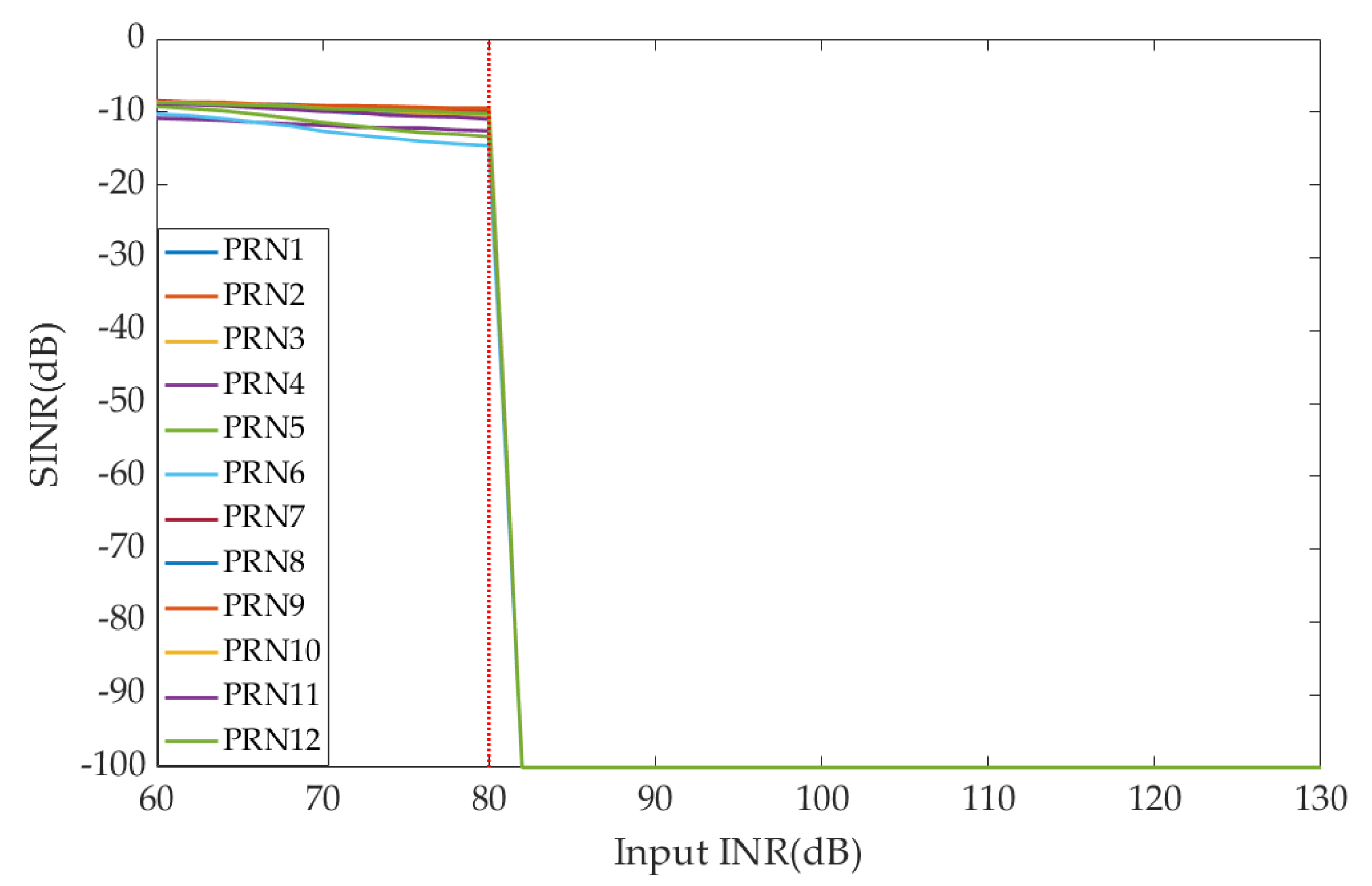
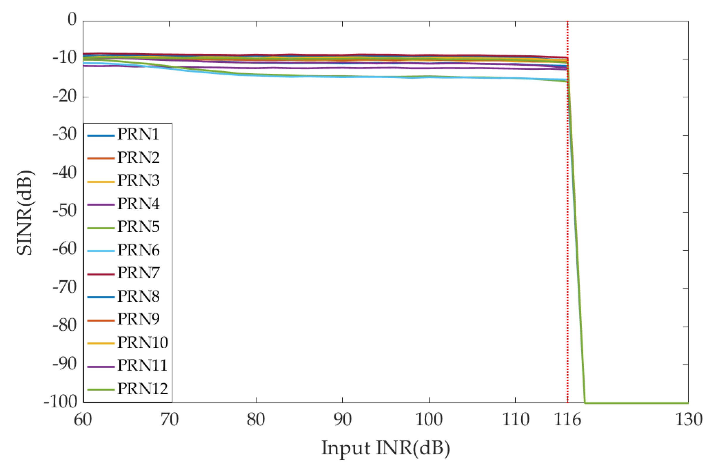
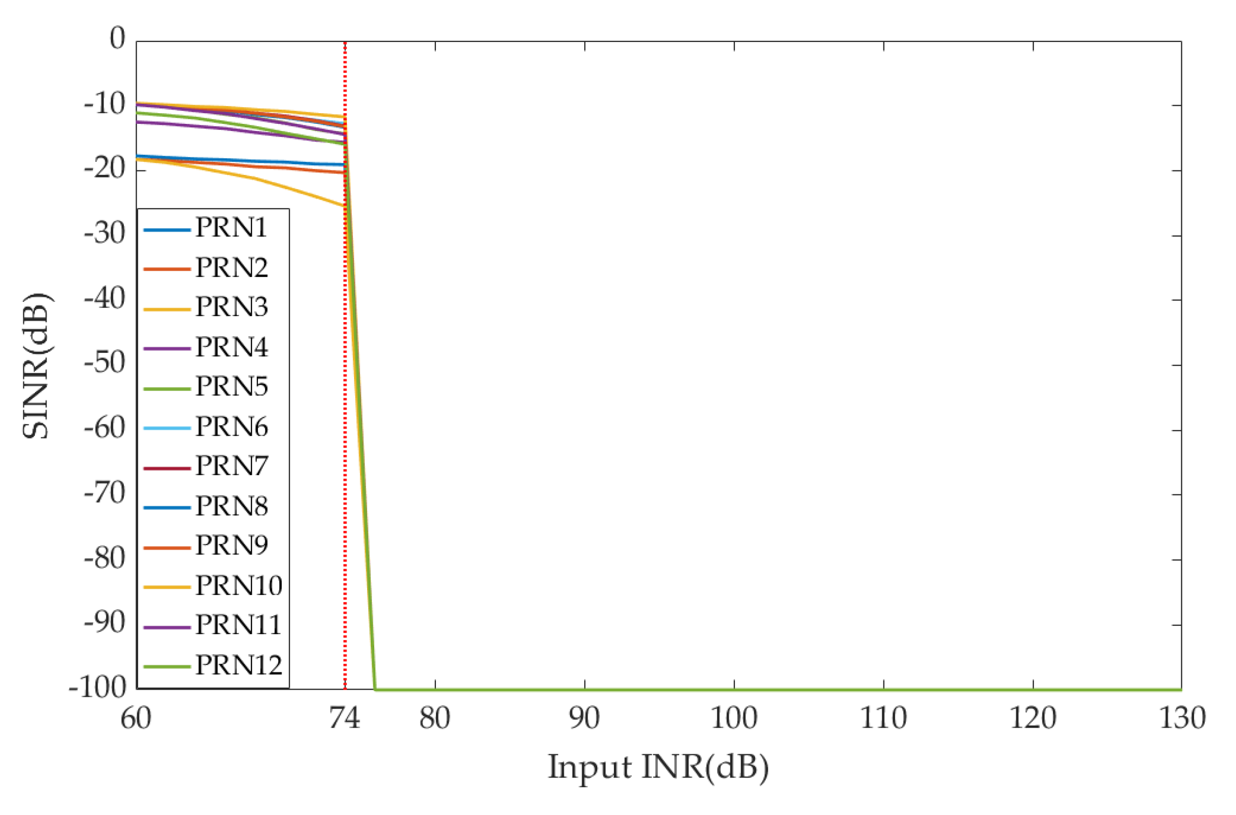
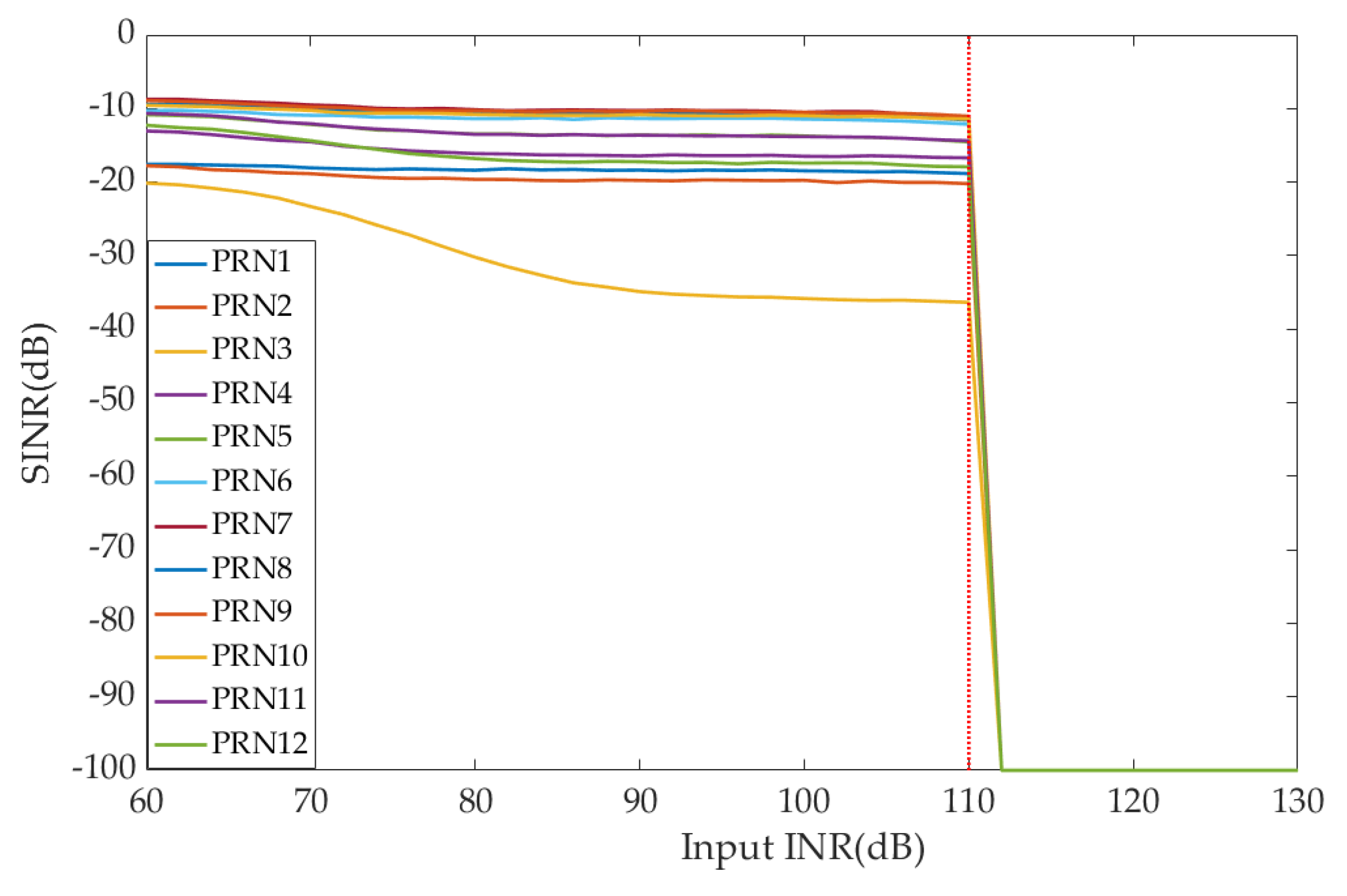
4.4. Experiment 3: Maximum Interference Suppression Abilty Performance Analysis
5. Discussions
6. Conclusions
- 1)
- A novel fully connected hybrid array anti-jamming receiver structure is proposed, which is used for hybrid beamforming by adding the attenuator and phase shifter array to the AFE.
- 2)
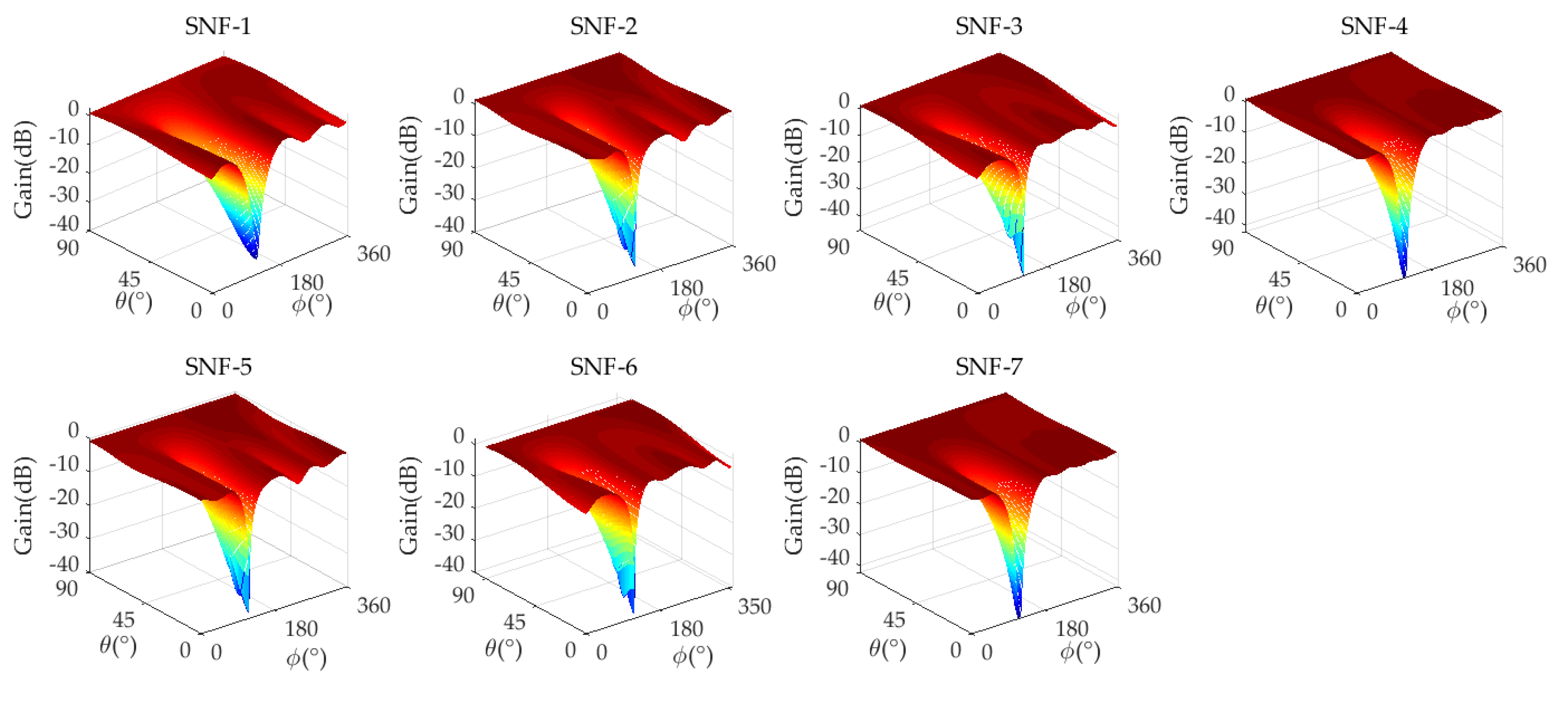
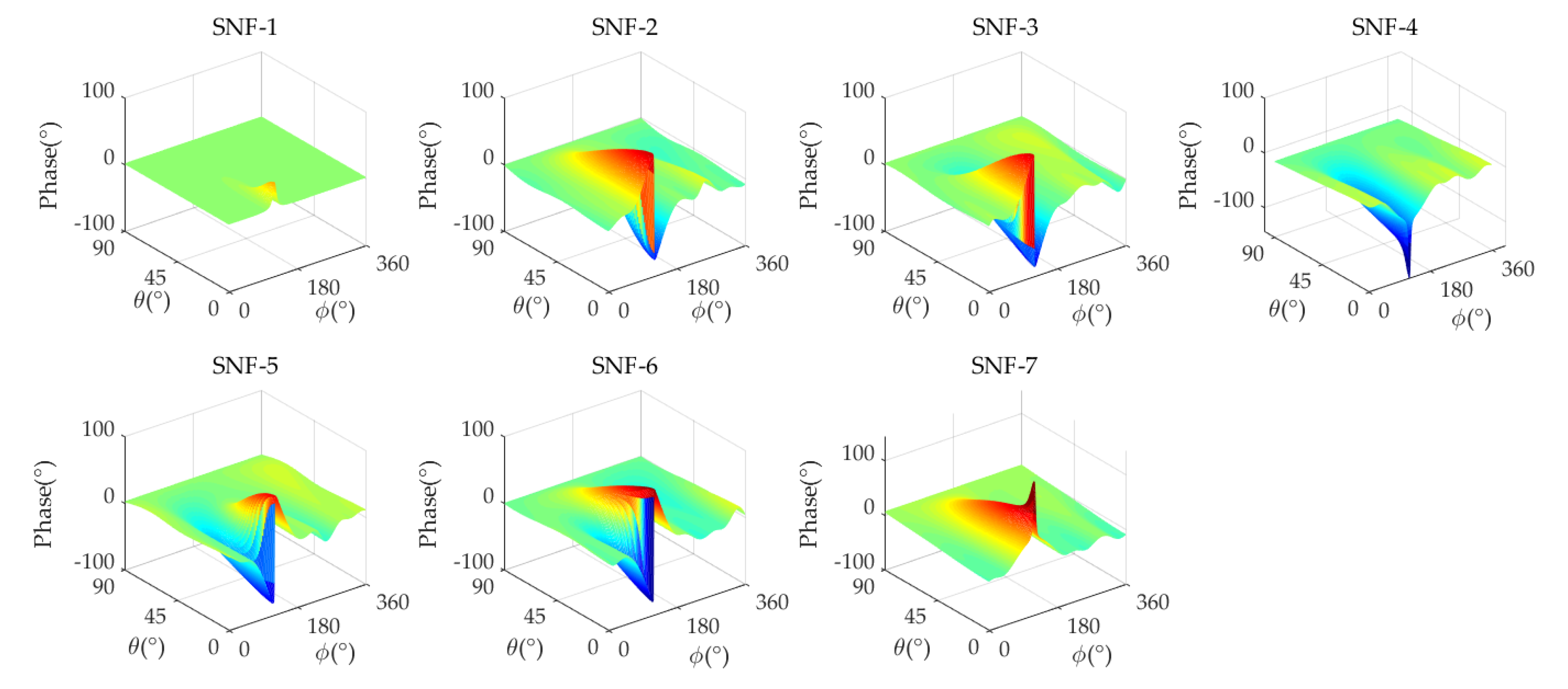
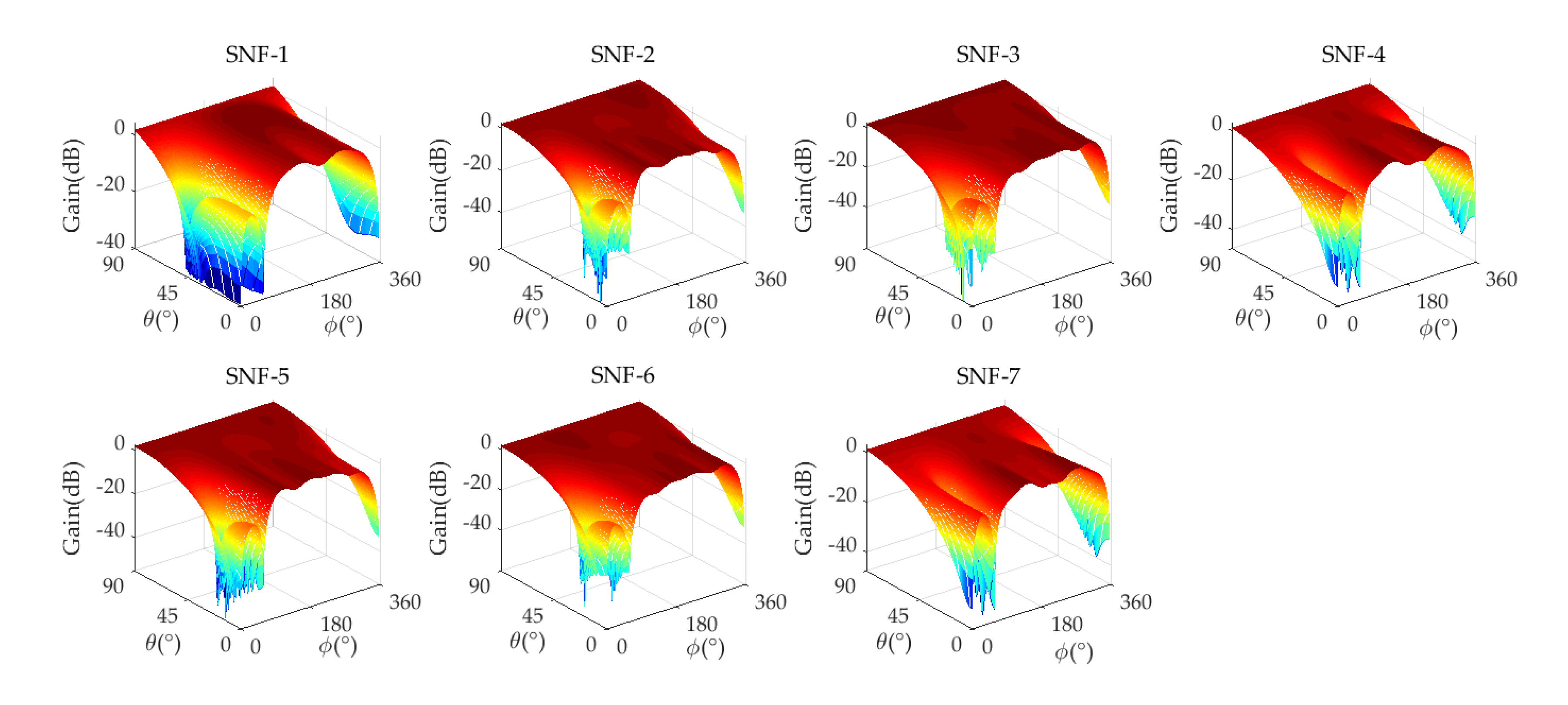
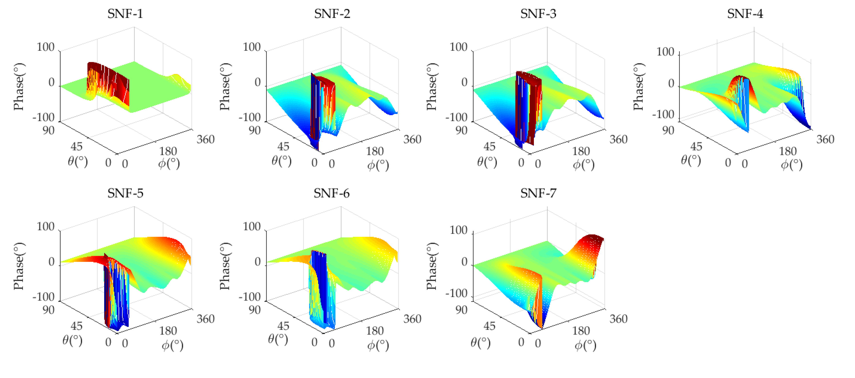
- A hybrid beamforming method for GNSS array antenna receiver is proposed. In analog domain, the interference is partially suppressed (better than 30 dB) by analog MNF generated by the baseband, and it relaxes the linear dynamic range of AFE to prevent saturation under the strong interference scenarios. In digital domain, the calibrated MVDR algorithm is used for the final suppression of residual interference.
- 3)
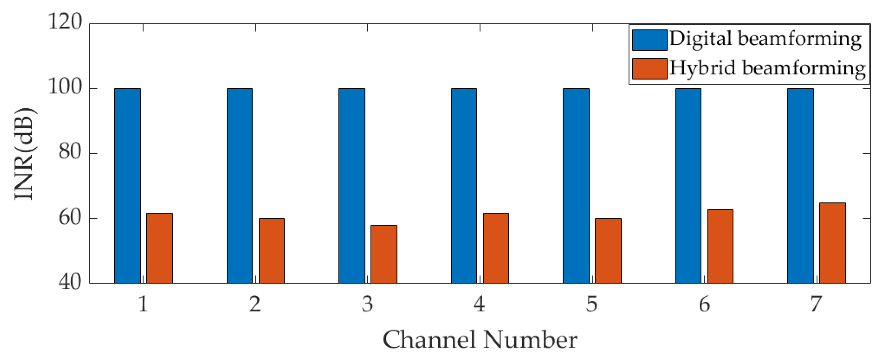
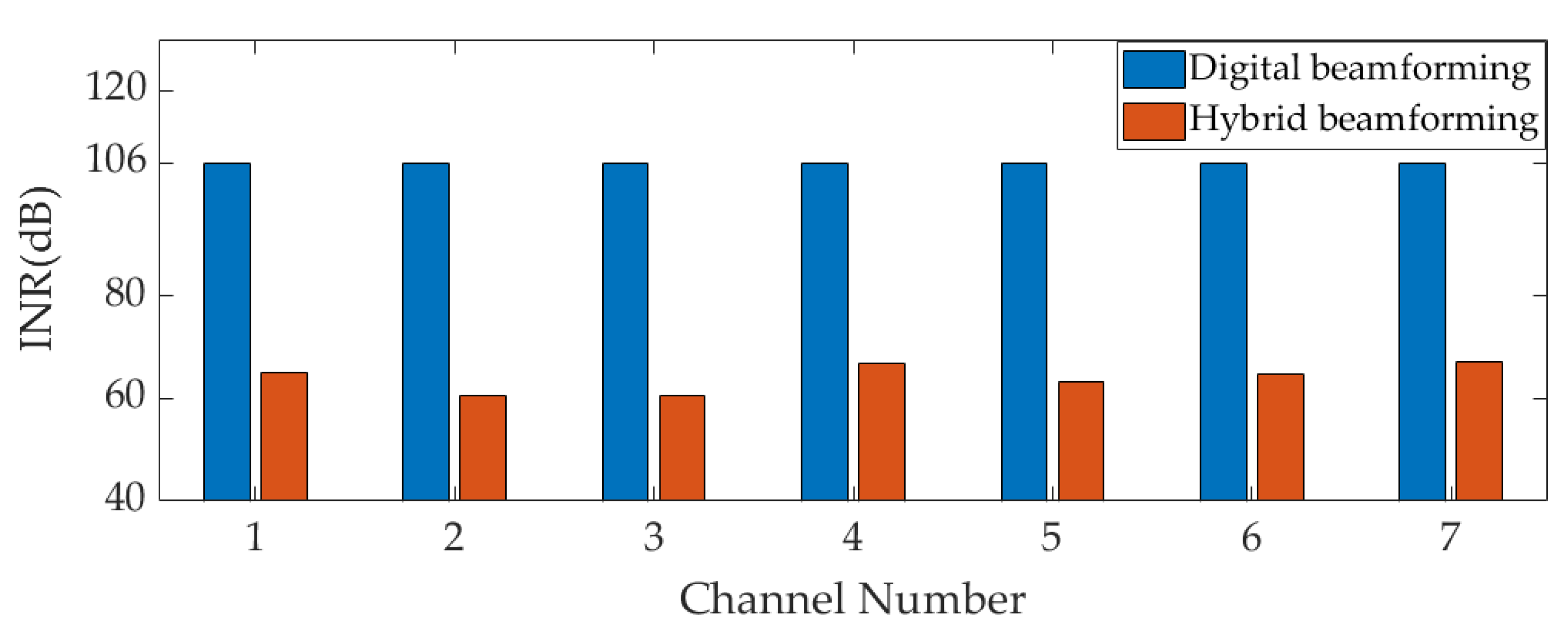
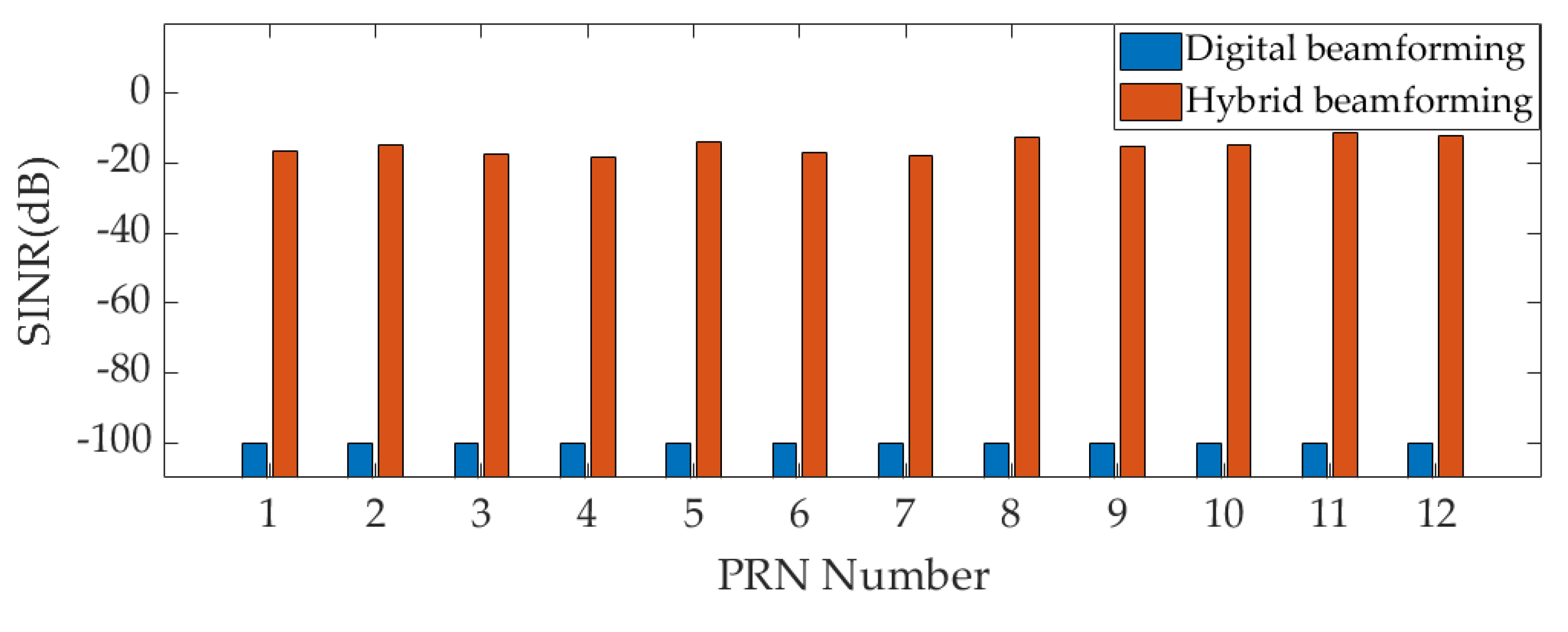
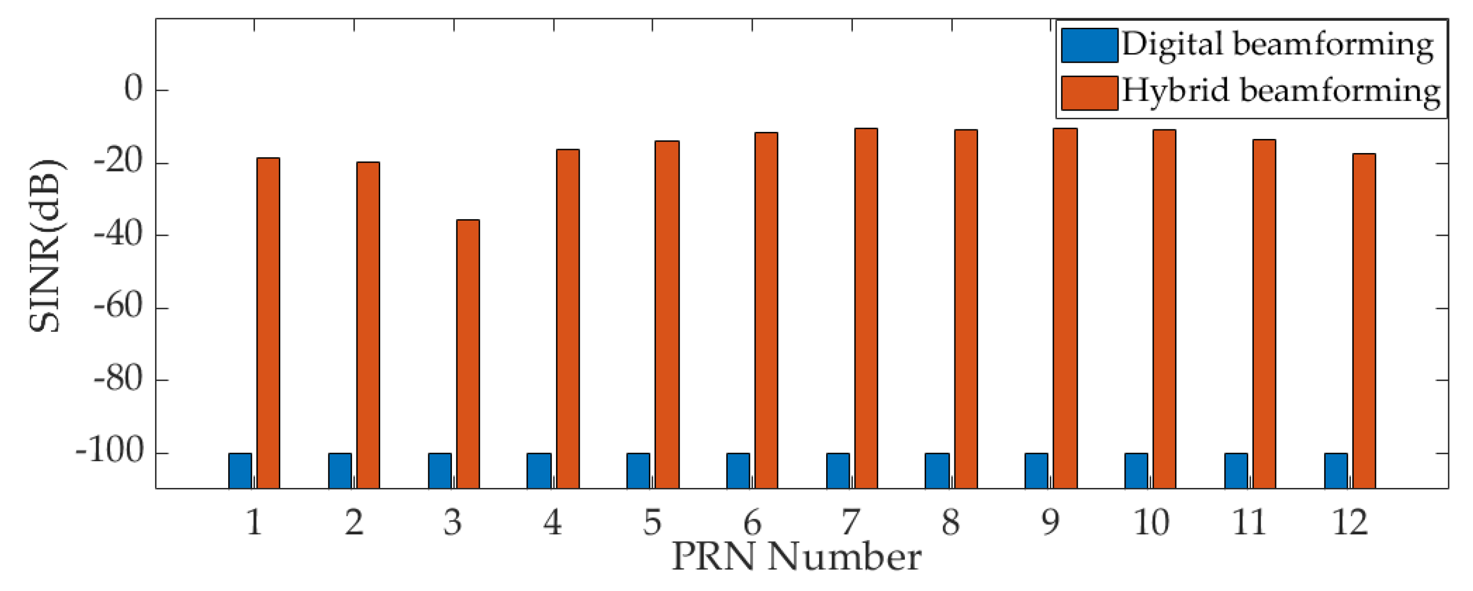
- Through two interference scenarios, compared with the digital beamforming- based array antenna receiver, it is verified that the maximum interference suppression ability of the hybrid beamforming-based array antenna receiver are improved by 36 dB under the conditions of using 7-bit attenuators and 8-bit phase shifters.
Author Contributions
Funding
Conflicts of Interest
References
- Chien, Y.R. Design of GPS Anti-Jamming Systems Using Adaptive Notch Filters. IEEE Syst J. 2015, 9, 451–460. [Google Scholar] [CrossRef]
- Ni, G.; He, C.; Jin, R. Single-Channel Anti-Jamming Receiver With Harmonic-Based Space-Time Adaptive Processing. IEEE Wirel. Commun. Lett. 2022, 11, 776–780. [Google Scholar] [CrossRef]
- Gioia, C.; Borio, D. Multi-layered Multi-Constellation Global Navigation Satellite System Interference Mitigation. Navigation. 2023, 70, 596. [Google Scholar] [CrossRef]
- Borio, D.; Gioia, C. GNSS interference mitigation: A measurement and position domain assessment. Navigation. 2021, 68, 93–114. [Google Scholar] [CrossRef]
- Kraus, T.; Pany, T.; Eissfeller, B. Maximum Theoretical Interference Mitigation Capability of a GNSS Receiver as Limited by the GNSS Frontend. Nat Microbiol. 2021, 6, 3471–3480. [Google Scholar]
- Borio, D.; Gioia, C. Interference mitigation: impact on GNSS timing. GPS Solut. 2021, 25, 37. [Google Scholar] [CrossRef]
- Borio, D.; Li, H.; Closas, P. Huber’s Non-Linearity for GNSS Interference Mitigation †. Sensors. 2018, 18, 2217. [Google Scholar] [CrossRef]
- Dovis, F. GNSS Interference Threats and Countermeasures. Artech House: Boston, USA, 2015; pp.62-64.
- 9. Betz,J.W. Engineering Satellite-Based Navigation and Timing: Global Navigation Satellite Systems, Signals, and Receivers. Wiley: New York, USA, 2016; pp.39-42.
- Li, Y.; Cervantes, J.; Shivaramaiah, N. C.; Akos, D. M.; Wang, M. Configurable GPS/GNSS Antenna Module Resistant to RFI Saturation. IEEE Trans. Aerosp. Eletron. 2020, 56, 381–392. [Google Scholar] [CrossRef]
- Huo, S.; Nie, J.; Tang, X.; Wang, F. Minimum Energy Block Technique Against Pulsed and Narrowband Mixed Interferers for Single Antenna GNSS Receivers. IEEE Commun. Lett. 2015, 19, 1933–1936. [Google Scholar] [CrossRef]
- Wu, K.; Zhang, J. A.; Huang, X.; Guo, Y. J.; Nguyen, D. N.; Kekirigoda, A.; Hui, K.P. Analog-Domain Suppression of Strong Interference Using Hybrid Antenna Array. Sensors. 2022, 22, 2417. [Google Scholar] [CrossRef] [PubMed]
- Krishnaswamy, H.; Zhang, L. Analog and RF Interference Mitigation for Integrated MIMO Receiver Arrays. Proc IEEE. 2016, 104, 561–575. [Google Scholar] [CrossRef]
- Golabighezelahmad, S.; Klumperink, E. A. M.; Nauta, B. A 0.7–5.7 GHz Reconfigurable MIMO Receiver Architecture for Analog Spatial Notch Filtering Using Orthogonal Beamforming. IEEE J. Solid-State. Circuits. 2021, 56, 1527–1540. [Google Scholar] [CrossRef]
- Lin, T.; Wei, X.; Lai, J.; Xie, M. Transmit Beamforming Design Based on Multi-Receiver Power Suppression for STAR Digital Array. Sensors. 2024, 24, 622. [Google Scholar] [CrossRef] [PubMed]
- Wang, G.; Yang, Z.; Gong, T. Hybrid Beamforming Design for Self-Interference Cancellation in Full-Duplex Millimeter-Wave MIMO Systems with Dynamic Subarrays. Entropy. 2022, 24, 1687. [Google Scholar] [CrossRef] [PubMed]
- Sun, Y.; Chen, F.; Lu, Z.; Wang, F. Anti-Jamming Method and Implementation for GNSS Receiver Based on Array Antenna Rotation. Remote Sens. 2022, 14, 4774. [Google Scholar] [CrossRef]
- Li, S.; Wang, F.; Tang, X.; Ni, S.; Lin, H. Anti-Jamming GNSS Antenna Array Receiver with Reduced Phase Distortions Using a Robust Phase Compensation Technique. Remote Sens. 2023, 15, 4344. [Google Scholar] [CrossRef]
- Li, S.; Lin, H.; Tang, X.; Ma, C.; Wang, F. Noncoherent Channel Combining for GNSS Signal Tracking with an Adaptive Antenna Array. Remote Sens. 2024, 16, 213. [Google Scholar] [CrossRef]
- Liang, J.; Zhang, X.; So, H. C.; Zhou, D. Sparse Array Beampattern Synthesis via Alternating Direction Method of Multipliers. IEEE Trans. Antennas. Propag. 2018, 66, 2333–2345. [Google Scholar] [CrossRef]
- Liang, J.; Fan, X.; Fan, W.; Zhou, D.; Li, J. Phase-Only Pattern Synthesis for Linear Antenna Arrays. IEEE Antennas Wirel. Propag. Lett. 2017, 16, 3232–3235. [Google Scholar] [CrossRef]
- de Lorenzo, D. S.; Lo, S. C.; Enge, P. K.; Rife, J. Calibrating adaptive antenna arrays for high-integrity GPS. GPS Solut. 2012, 16, 221–230. [Google Scholar] [CrossRef]
- Mills, K.; Ahmad, F.; Amin, M. G.; Himed, B. Mills, K.; Ahmad, F.; Amin, M. G.; Himed, B. Fast Iterative Interpolated Beamforming for Interference DOA Estimation in GNSS Receivers Using Fully Augmentable Arrays. 2019 IEEE Radar Conference (Radar Conf), Boston, MA, USA,22-26 April 2019.
| Parameters | Value |
|---|---|
| RF frequency f | 1575.42 MHz |
| Number of antenna elements | M = 7 |
| Array radius | R=λ/2 |
| Signal bandwidth | 20.46 MHz |
| Interference bandwidth | 20.46 MHz |
| Bits of attenuator | 7 bit |
| Bits of phase shifter | 8 bit |
| Bits of ADC | 16 bit |
| RF gain | 30 dB |
| GNSS signal power | −120 dBm |
| Noise power | −100 dBm |
| Scenario | Number of Interference | Interference’s DOA |
|---|---|---|
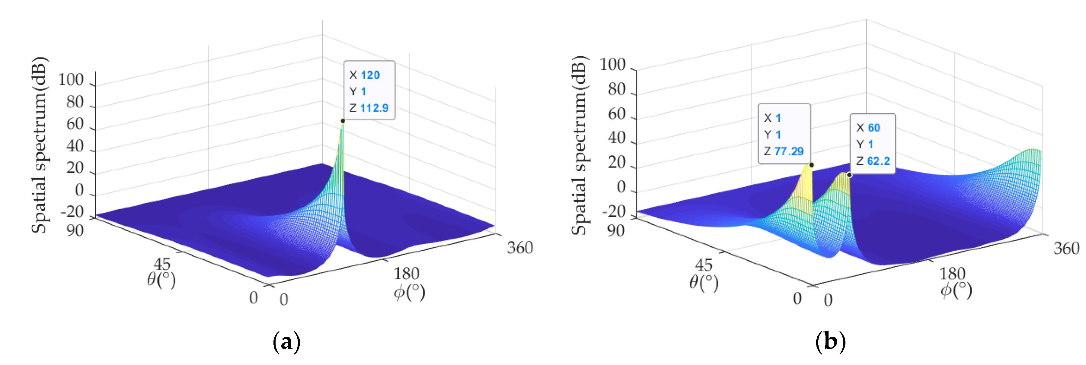
| Scenario 1 | 1 | (1°,120°) |
| Scenario 2 | 2 | (1°,1°), (1°,120°) |
| PRN | Azimuth( ) | Elevation ( ) |
|---|---|---|
| 1 | 0° | 40° |
| 2 | 30° | 30° |
| 3 | 60° | 40° |
| 4 | 90° | 30° |
| 5 | 120° | 80° |
| 6 | 150° | 60° |
| 7 | 180° | 20° |
| 8 | 210° | 70° |
| 9 | 240° | 20° |
| 10 | 270° | 30° |
| 11 | 300° | 80° |
| 12 | 330° | 60° |
| Parameters | Value |
|---|---|
| 0.5 | |
| 0.15 | |
| SNF Number | D | ||||||
|---|---|---|---|---|---|---|---|
| SNF-1 | −1.345 | 2.687 | −35.07 | \ | \ | \ | \ |
| SNF-2 | −2.776 | 1.727 | −36.56 | 0.646 | 3.030 | 3.96 | 15.81 |
| SNF-3 | −2.912 | 1.809 | −45.20 | 0.655 | 3.024 | 3.57 | 17.47 |
| SNF-4 | −0.716 | 1.221 | −42.25 | 0.734 | 2.420 | 3.77 | 16.95 |
| SNF-5 | −4.683 | −0.180 | −38.47 | 1.812 | 4.508 | 3.69 | 17.29 |
| SNF-6 | −2.896 | 1.791 | −38.90 | 0.652 | 3.008 | 3.86 | 16.21 |
| SNF-7 | −0.716 | 1.221 | −42.25 | 0.734 | 2.420 | 3.67 | 15.50 |
| SNF Number | ||||||||
|---|---|---|---|---|---|---|---|---|
| SNF-1 | 1.016 | 1.646 | −39.40 | −38.58 | \ | \ | \ | \ |
| SNF-2 | 0.848 | 1.355 | −44.43 | −35.86 | 0.993 | 4.123 | 3.431 | 17.47 |
| SNF-3 | 0.849 | 1.345 | −50.99 | −37.93 | 1.006 | 4.477 | 3.451 | 17.35 |
| SNF-4 | 0.687 | 1.456 | −42.92 | −39.96 | 1.012 | 4.377 | 2.365 | 18.49 |
| SNF-5 | 0.841 | 1.365 | −37 | −39.77 | 1.003 | 4.004 | 3.402 | 18.07 |
| SNF-6 | 0.858 | 1.350 | −34.22 | −36.18 | 1.016 | 4.324 | 3.344 | 18.07 |
| SNF-7 | 0.687 | 1.456 | −39.96 | −42.92 | 1.012 | 4.459 | 2.348 | 17.39 |
Disclaimer/Publisher’s Note: The statements, opinions and data contained in all publications are solely those of the individual author(s) and contributor(s) and not of MDPI and/or the editor(s). MDPI and/or the editor(s) disclaim responsibility for any injury to people or property resulting from any ideas, methods, instructions or products referred to in the content. |
© 2024 by the authors. Licensee MDPI, Basel, Switzerland. This article is an open access article distributed under the terms and conditions of the Creative Commons Attribution (CC BY) license (http://creativecommons.org/licenses/by/4.0/).


