1. Introduction
The beam of Flat-top (also called top-hat) laser beams was characterized by having a homogeneous distribution of beam intensity in the center with nearly sharp beams at two edges [
1,
3]. These kinds of beams are very helpful for diverse applications including laser engraving, selected laser melting, laser micro
-fabrication, laser radar, and optical metrology [
4,
5]. By using an optical beam shaper the Gaussian ray laser can be turned into a flat-top laser beam [
6] such as holograms [
7], Binary Phase Plate [
4], and hybrid grating [
8] for example but not limited. The atmospheric effects on laser beam propagation can be categorized as attenuation of the laser power and fluctuation caused by beam distortion
. The photons of laser light can be attenuated by absorption and scattering due to interaction with aerosols and gaseous molecules in the atmosphere. On the other hand, Small-scale dynamic variations in the atmosphere's index of refraction cause laser beam distortion. As a result, the laser beam wanders, spreads, and distorts the wave front or exhibits scintillation. For short-range propagation ns, the laser beam undergoes fewer fluctuations is and less distorted. The deformation of a beam using a method of small perturbing actions is often referred to as the Rytov Method and laser applications [
9,
10,
11,
12,
13]. As a laser beam travels across several kilometers, it experiences strong fluctuations causing the deformity cross-sections section of that beam into a speckled pattern. The investigations of this work aimed at modeling A flat-top Gaussian beam, the field as it propagates via atmospheric turbulence, causes to producing beam scintillation and wander are established in order to make a comparison with experimental results.
2. Effect of Flat-Topped Gaussian Beamwidth on Average Intensity
The intensity diffusion of the proportional FTG beam at the sender plane (U
T) is found in z = 0, and the parataxis presented by [
14] can be used as given by Eq. 1
Here
UT is Intensity spread at the source plane, A is the field scattering amplitude,
s is the cross vector at the sender plane,
w0 are middle of the spectrum and the
N integer number represents superficies ranking. Density spreading at the receiver level
UR They will be able to choose to use the Huygens - Fresnel integral as beneath [
15].
Wherever the parameters of the equation above,
z are defined as the space amidst the planes
T (transmitter) and
R (receiver),
r is the slope vector in the
R plane, and wave number
k. Moreover, the outdo spread of the FTG beam, and convolution of Eq. (2) and Eq. (3) without turbulent plenty enlargement function is required as given by [
16].
Turbulence affects laser radiation, causing temporal and spatial changes in irradiance that are visible at the receiving plane. the scintillation index of the phase is related to beam fluctuation and is usually measured in space.
where
is denoted scintillation index and
I refer to the light intensity. The Rytov variance can be used to characterize scintillation
when a model of an unobstructed flat wave or circular wave is utilized.
The refractive index fluctuations and the Kolmogorov power-law spectrum only occur among inertia-band vortices K (rad m
-1). It is isotropic and limited to homogeneous.
The parameter
Cn acts as a deflective index of structure constant (m
−2/3) and the
l0,
L0 is the inner and outer turbulence measure, correspondingly. The direction along which light propagates depends on whether its medium is homogeneous or not and heterogeneous
. Moreover, the degree of refractive index structure constant governs to that the refractive index of a medium vacillates. In the fact of the values order of 10
-17 m
−2/3 is accompanying occurred in weak turbulence to up it, consequently, the section of reasonable turbulence is
. The grade of turbulence is advanced at minor elevations as mentioned above. Additionally, the higher values of
results are nearer to the ground level. Eq.7 is defined the refractive index of structure constant as below.
Somewhere the factors CT, P, and T, are delighted with the temperature (K) of structure constant, the pressure (m bar) indoors of the turbulence model.
3. Results and Analysis
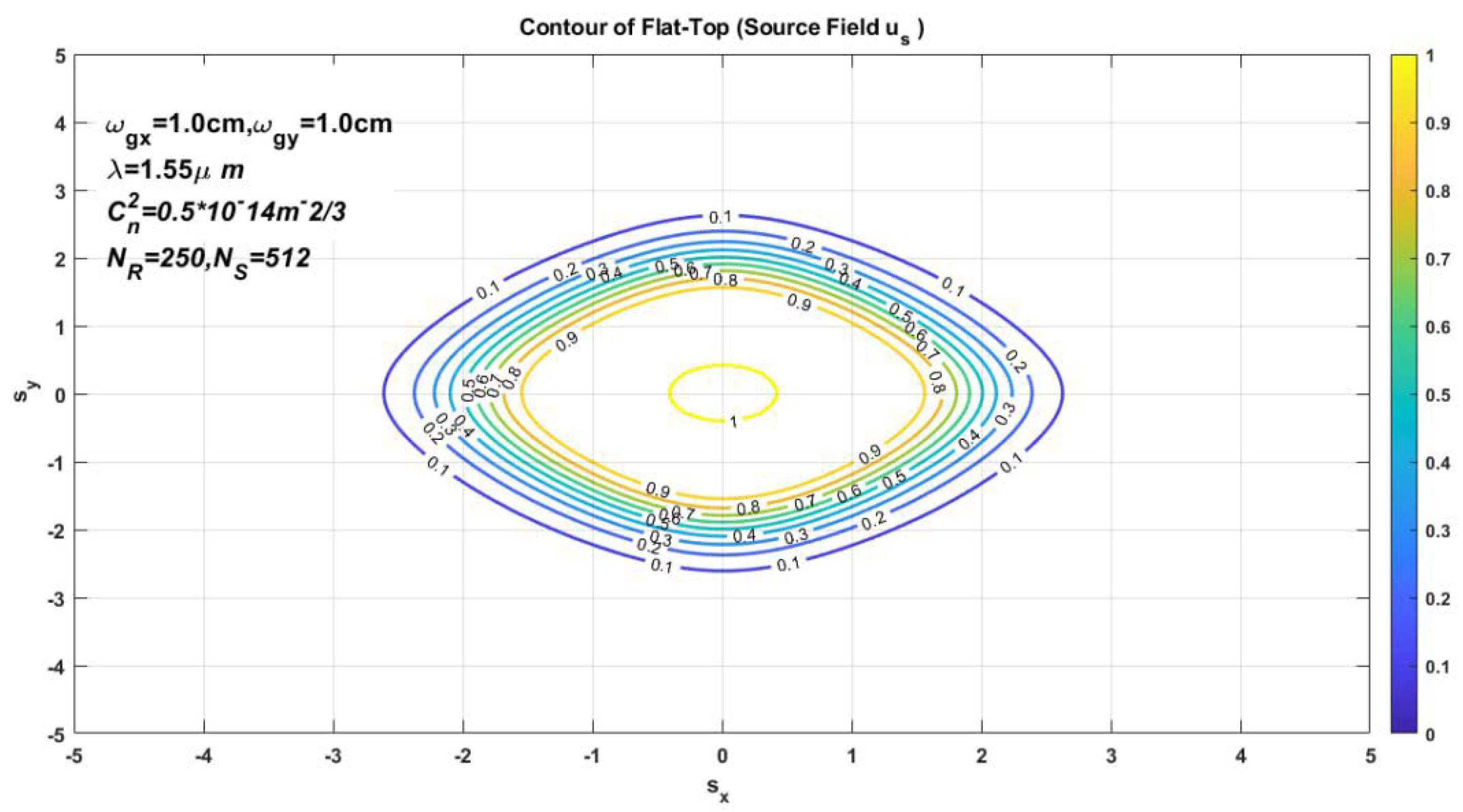
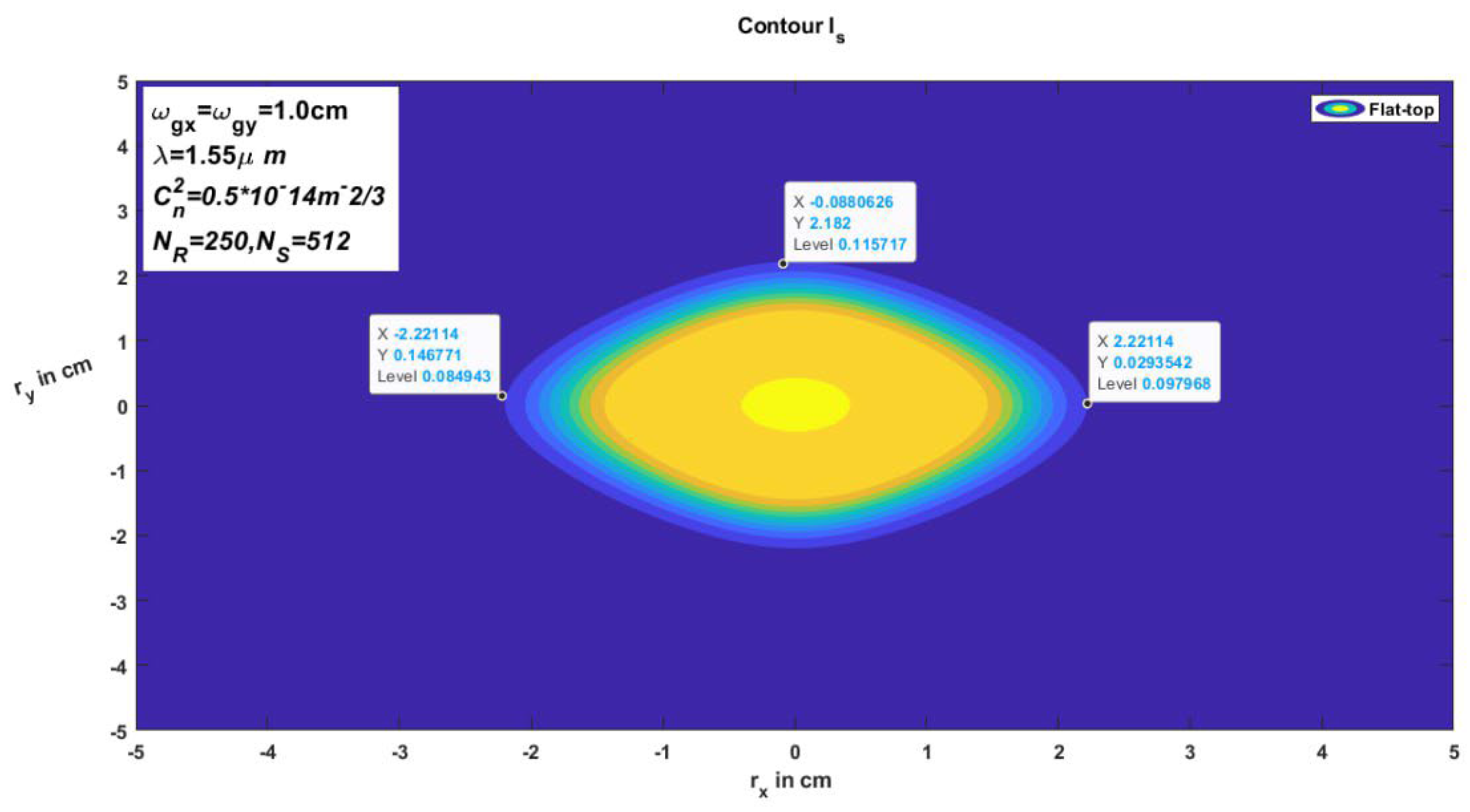
In this Sector, we are using some numerical examples of the different intensity developments of FTG for dissimilar distances in a turbulence atmosphere accomplished according to Eqs. (1&2). Furthermore, to explain the outcomes of several figures like intensity, scintillation index, contour, and so on, moreover, to apply these parameters, for example, the wavelength λ= 1550 nm, source size , and structure constant parameter 10−13 m−2/3 of the Gaussian beam, additionally, to added other factors have been displayed in all figures.
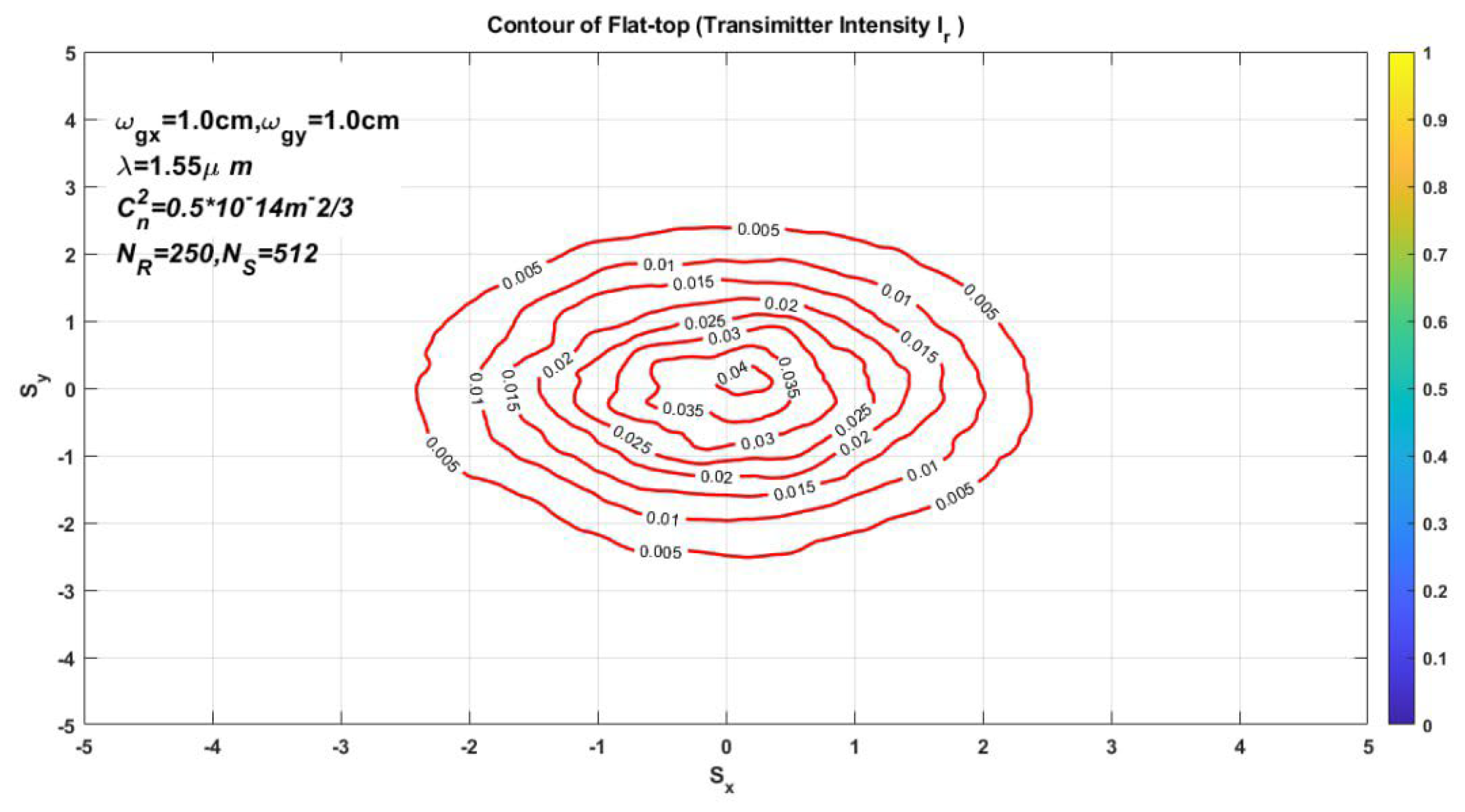
Figure 1. the contour for flat top Gaussian ray of the basic field, we observed the lines in the center are dissimilar on the other line that’s back to equality of source size (x&y) axis, conclusively,
Figure 2. source intensity of flat top Gaussian beam in the oblique coordinate structure, thereby like the previous figure but applied color and referring to values of boundary lines. Similarly,
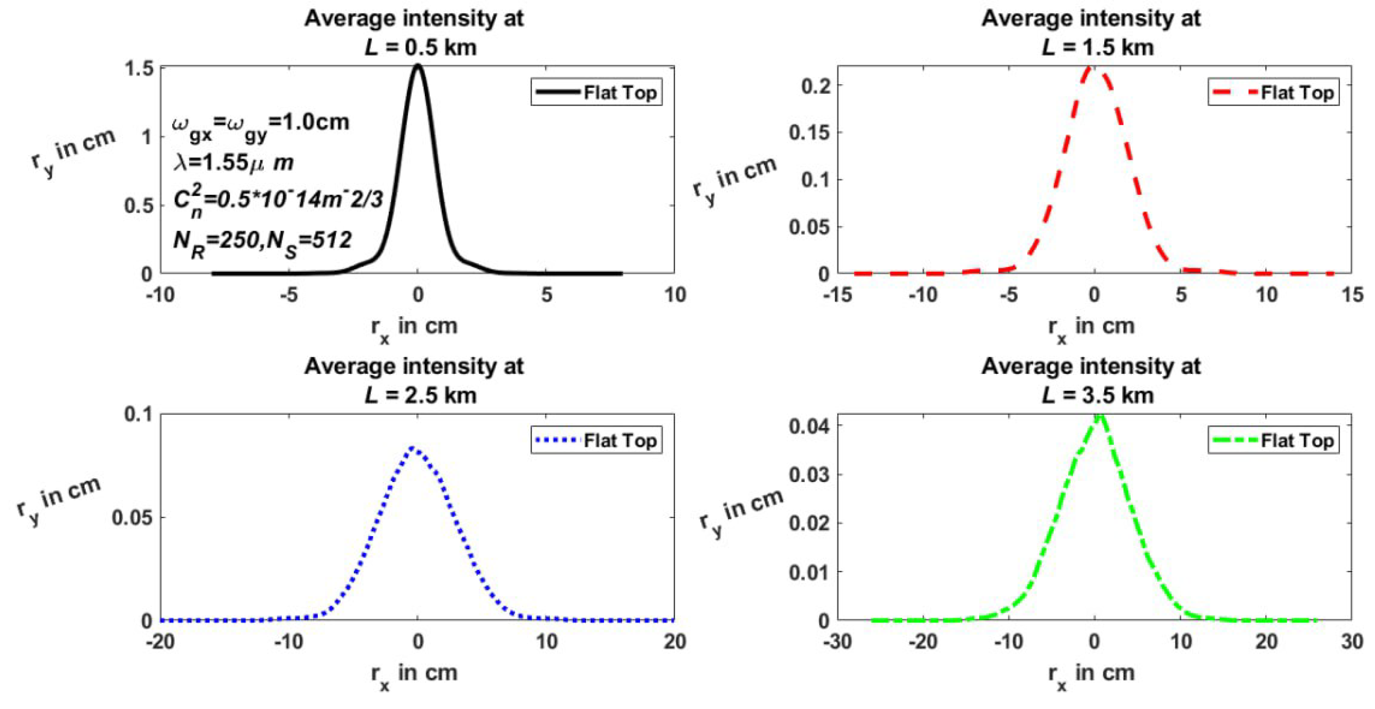
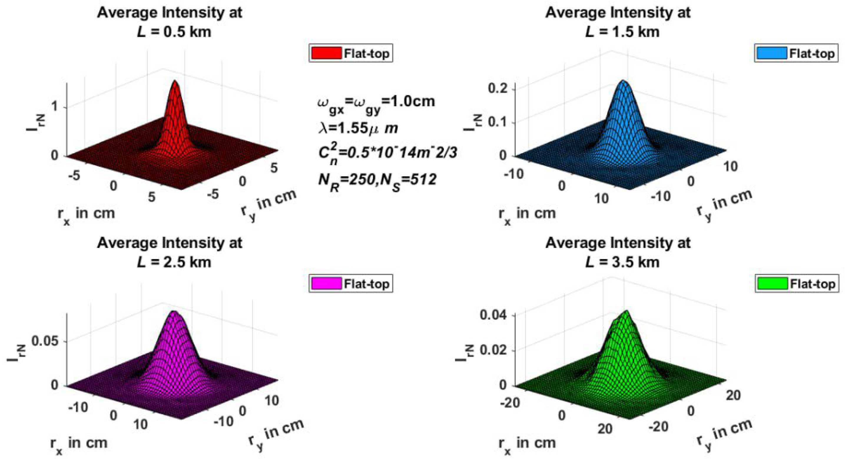
Figure 3 and
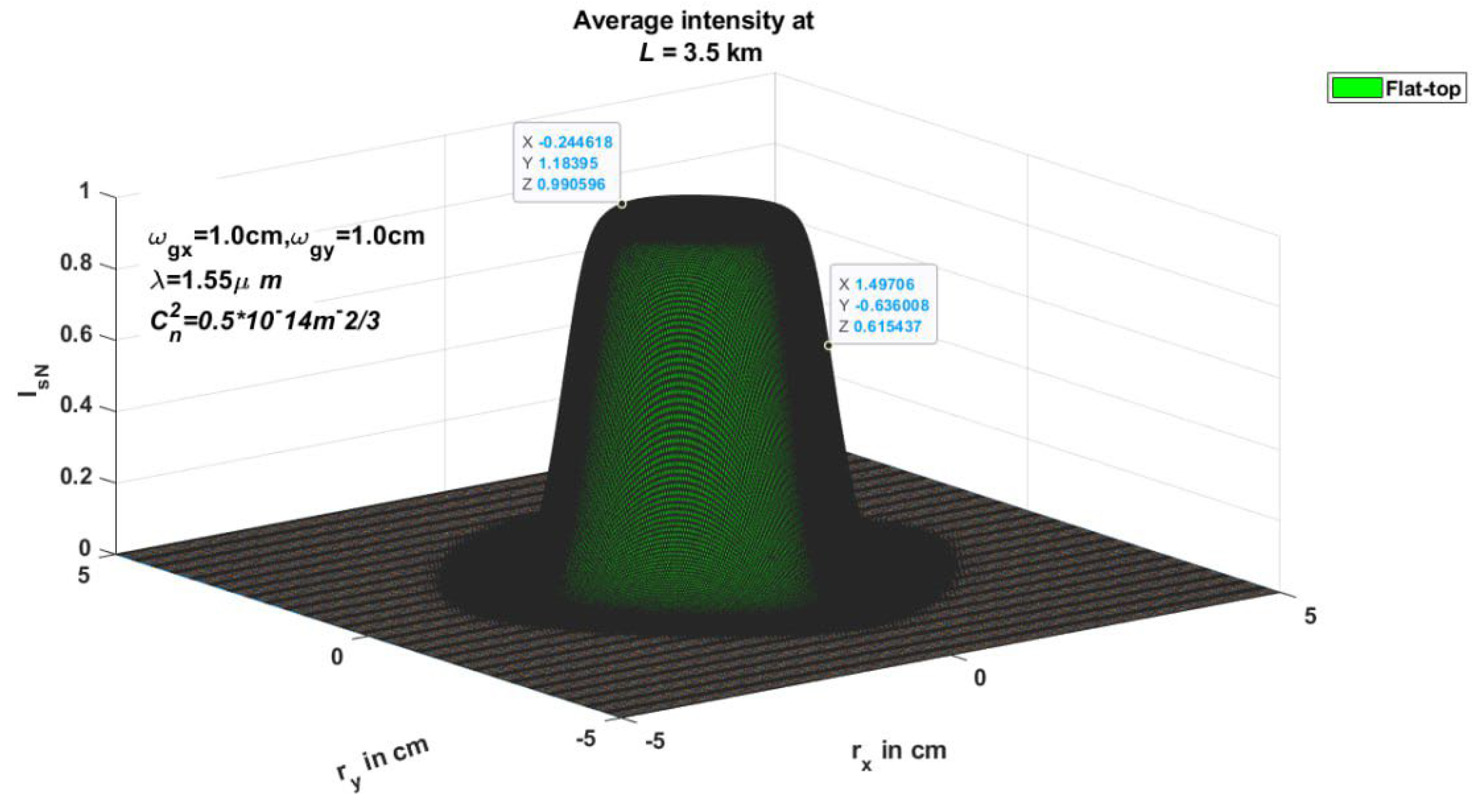
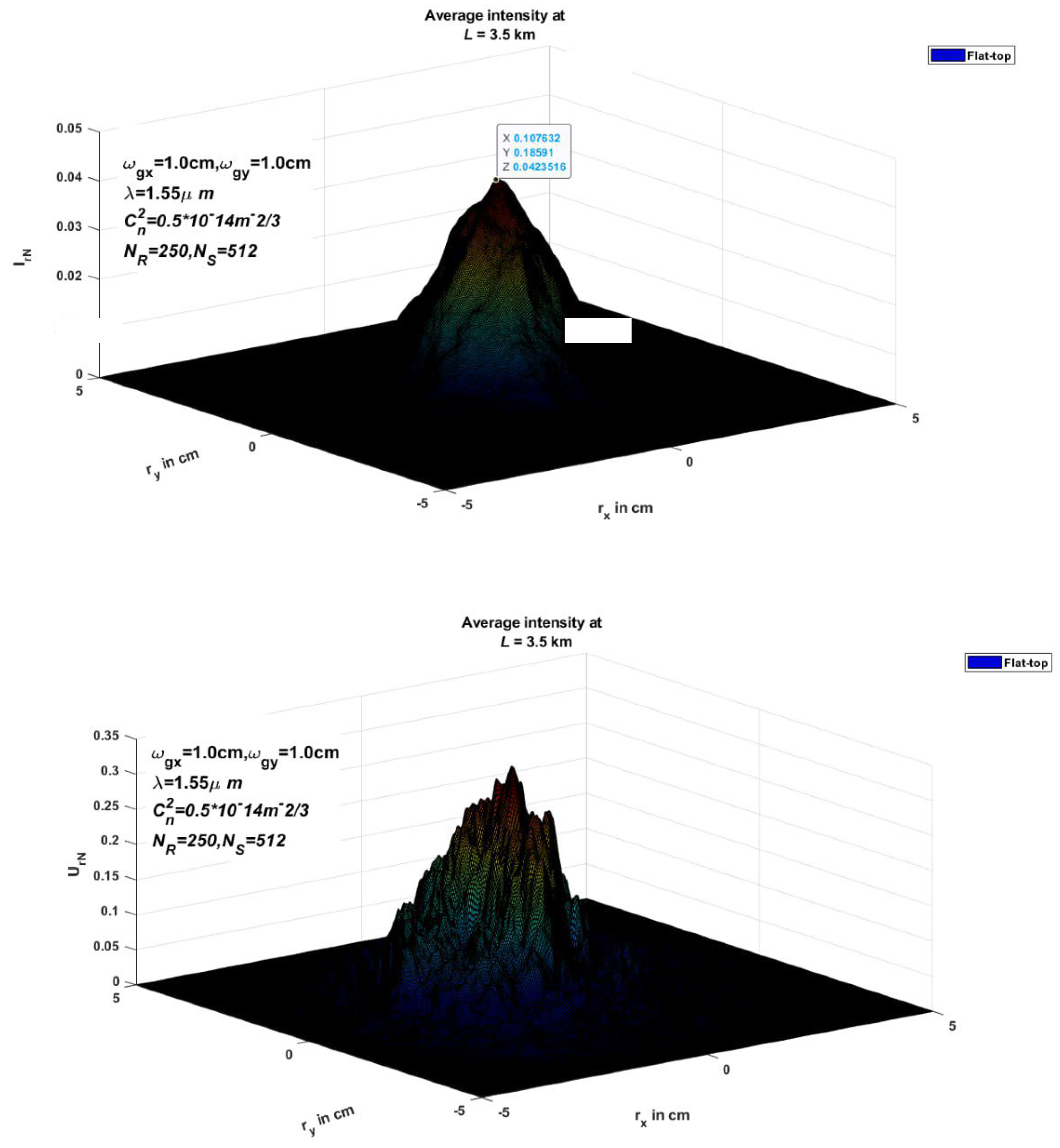
Figure 4 are illustrated the average intensity of FTG Beam in 2-D and 3-D Transverse Coordinate System Interetingly for different distances. Besides,
Figure 5 refers to the 3D of average Intensity for the FTG beam in the transmitter plan, in addition to besides, spreads in atmospheric space with distribution as propagation distance rises. On the other hand, the intensity shape will adopt a bright center core comparable to the flat-top Gaussian profile.
In this perspective,
Figure 2 provides the source intensity of the flat-top Gaussian ray in the slanting coordinate system dependent on the parameters mentioned earlier, intensity contour loops describe the constant distance between two circles. so, the constant construction stricture, wavelength, is usage. In addition,
Figure 3 and
Figure 4 show the variation of source intensity with different propagation distances L= (0.5, 1.5, 2.5, 3.5) km in the oblique coordinate classification of two and three dimensions respectively
As a matter of fact,
Figure 4. Illustrate the receiver field, indicating a reduction in receiver intensity in comparison with the amplitude of the source as the beam diffusion is passing the far distance of 3.5 km from the source to the receiver plane. Similarly, representative simulated results concerning the variation of source amplitude at different propagation distances and contour rings at the receiver plane are displayed in
Figure 6 and
Figure 7. Specifically,
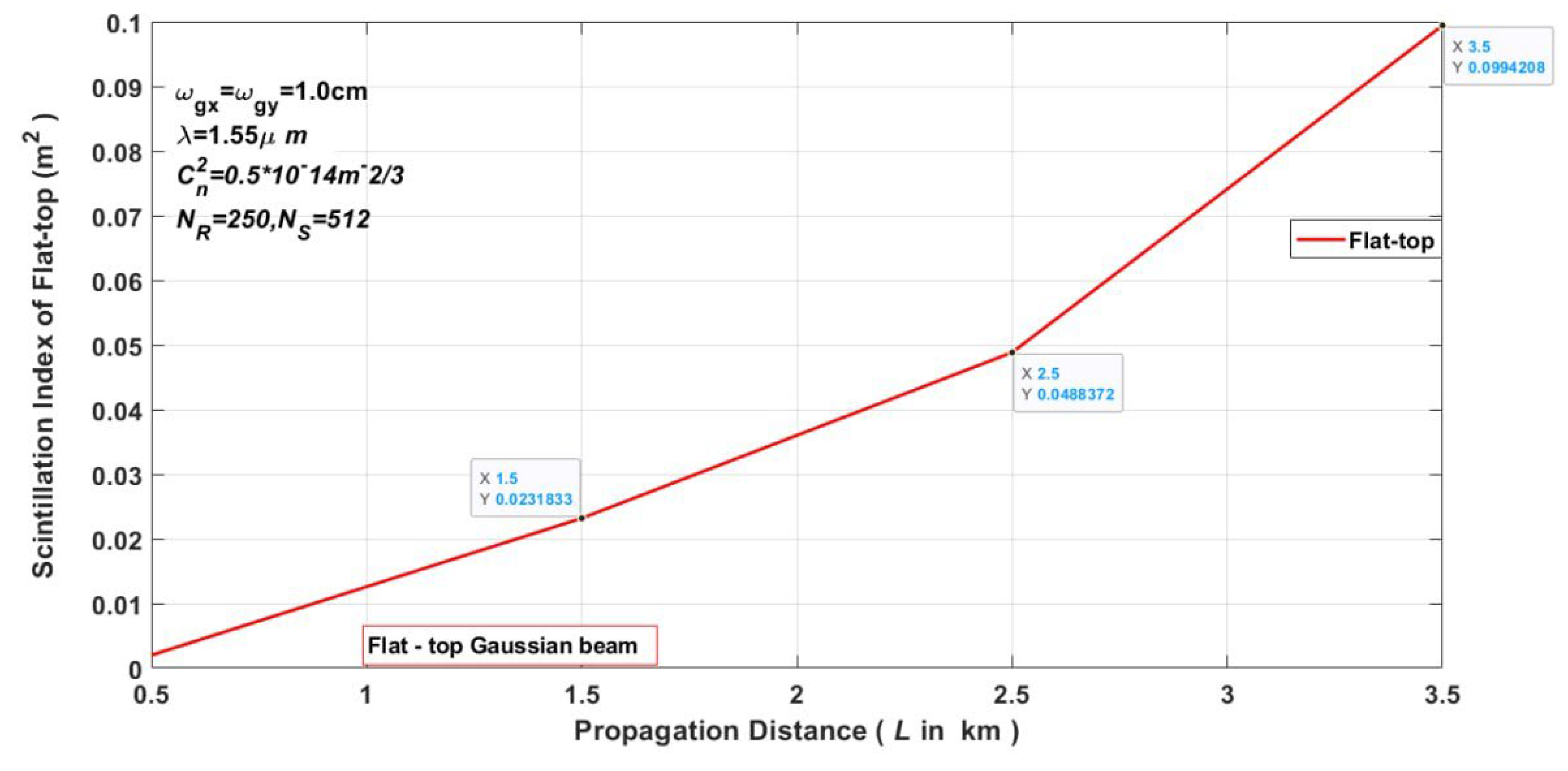
Figure 8 focuses on the variation of the scintillation index with fixed wavelength FTG beam versus propagation distance which shows the scintillation increases linearly to the far 2.5 km and for up that’s raised high scintillation. As the initial wave front of the laser beam propagates via turbulence zones it would undergo variance in irradiance causing temporal and spatial changes in irradiance that are visible at the receiver. The on-axis scintillation index calculated by Eq. 3 is commonly used to assess the degree of variation in the received signal.
4. Conclusions
In this paper, the near-field proliferation of the FTG beam through a puny atmosphere is mathematically simulated. The analysis was performed with the help of the fragmented beam propagation technique. It is shown that the propagation of an FTG beam with a high uniformity parameter can be analyzed as the deflection of a plane wave occurrence on a spherical gap with an extent equivalent to that of the FTG beam at the T plane. The two and three-dimension intensity possessions were accurately held. The rising scintillation index proportion constant produced a larger distortion in receiver intensity. In fact, the finding is valuable for applications in not only optical communication systems but also in laser material interaction applications.
Declarations
I herewith declare that the information in this article is true and correct and that the contents and value of this freight are as specified.
Author Contributions
The study's idea and design, data collection, analysis, and result interpretation are all solely the author's responsibility, the author affirms.
Funding
This article's preparation was not supported financially in any way.
Institutional Review Board Statement
Ethical Publications Approve the Authors.
Data Availability Statement
Each and every piece of data created or examined for this study was unique, and the author was given their privacy back based on how it was used in the final publication.
Acknowledgments
The author is grateful to Al-Nahrain University, Engineering College, Department of Laser and Optoelectronic Engineering.
Conflicts of Interest
The author certifies that they don't have any known financial conflicts of interest that would appear to affect the work they provide in this article.
References
- Saghafi, S.; Withford, M.J.; Ghoranneviss, Z. Characterizing flat-top laser beams using standard beam parameters. Can. J. Phys. 2006, 84, 223–240. [Google Scholar] [CrossRef]
- Eyyuboglu, H.T.; Arpali, Ç.; Baykal, Y.K. Flat-topped beams and their characteristics in turbulent media. Opt. Express 2006, 14, 4196. [Google Scholar] [CrossRef] [PubMed]
- Baykal, Y.; Eyyuboǧlu, H.T. Scintillation index of flat-topped Gaussian beams. Appl. Opt. 2006, 45, 3793–3797. [Google Scholar] [CrossRef]
- Khame, Hussein Thary, and Sameer Algburi. Laser beam blink propagation: Evaluation BER in free space resembled dual SLG. Optics and Lasers in Engineering 2023, 171, 107761. [Google Scholar] [CrossRef]
- Wang, Y.; Shi, J. Materials Characterization Developing very strong texture in a nickel-based superalloy by selective laser melting with an ultra-high power and flat-top laser beam. Mater. Charact. 2020, 165, 110372. [Google Scholar] [CrossRef]
- Liu, C.; Guo, Y. Flat-Top Line-Shaped Beam Shaping and System Design. Sensors 2022. [Google Scholar] [CrossRef] [PubMed]
- Miler, M. Holographic Gaussian to flat-top beam shaping. Opt. Eng. 2003, 42, 3114. [Google Scholar] [CrossRef]
- Zhai, Z.; Gao, T.; Zhang, Y.; Lv, Q.; Wang, X.; Xie, B. Flattop Beam Shaping Using Hybrid Gratings. IEEE Photonics J. 2022, 14, 1–5. [Google Scholar] [CrossRef]
- Kinani, A.; Ez-Zariy, L.; Chafiq, A.; Nebdi, H.; Belafhal, A. Effects of atmospheric turbulence on the propagation of Li’s flat-topped optical beams. Phys. Chem. News 2011, 61, 24–33. [Google Scholar]
- Khamees, H.T. Laser Gaussian beam analysis of structure constant depends on Kolmogorov in the turbulent atmosphere for a variable angle of wave propagation. Journal of Laser Applications 2022, 34, 022017. [Google Scholar] [CrossRef]
- Khamees, H.T. Average intensity of SLVGB for slant path propagation in atmospheric turbulent. Results in Optics 2021, 5, 100159. [Google Scholar] [CrossRef]
- Khamees, H.T. Atmospheric Propagation Model and affecting on laser beam propagation via Free Space. Frontiers in optics, OSA technical digest 2017. [Google Scholar]
- Bagini, V.; Borghi, R.; Gori, F.; Pacileo, A.M.; Santarsiero, M. Propagation of axially symmetric flattened Gaussian beams. Journal of the Optical Society of America A 1996, 13, 1385–1394. [Google Scholar] [CrossRef]
- Khamees, H.T.; Hussein, A.S.; Abdulkhaleq, N.I. An evaluation of scintillation index in atmospheric turbulent for new super Lorentz vortex Gaussian beam. TELKOMNIKA (Telecommunication Computing Electronics and Control) 2023, 21, 1–7. [Google Scholar] [CrossRef]
- Khamees, H.T.; Majeed, M.S. A receiver intensity for Super Lorentz Gaussian beam (SLG) propagation via the moderate turbulent atmosphere using a novelty mathematical model. Journal of Optical Communications 2020. [Google Scholar] [CrossRef]
- Khamees, H.T.; et al. Structure constant analyzing of SLG beam Kolmogorov in atmospheric slant path propagation. AIP Conference Proceedings. 2019, 2129, 020063. [Google Scholar]
- Khamees, H.T.; Al-Ghrairi, A.H.; Mohammed, A.A. Switched-line network with digital phase shifter. International Journal of Nonlinear Sciences and Numerical Simulation 2023, 24, 1215–1220. [Google Scholar] [CrossRef]
|
Disclaimer/Publisher’s Note: The statements, opinions and data contained in all publications are solely those of the individual author(s) and contributor(s) and not of MDPI and/or the editor(s). MDPI and/or the editor(s) disclaim responsibility for any injury to people or property resulting from any ideas, methods, instructions or products referred to in the content. |
© 2024 by the authors. Licensee MDPI, Basel, Switzerland. This article is an open access article distributed under the terms and conditions of the Creative Commons Attribution (CC BY) license (http://creativecommons.org/licenses/by/4.0/).
