Submitted:
24 April 2024
Posted:
24 April 2024
You are already at the latest version
Abstract
Keywords:
1. Introduction
2. Working Principle and Design Method of Anti-Rocking Bearings
2.1. Structural Construction and Working Principle
2.2. Stiffness Calculation
2.3. Design of Bearing Parameters
2.4. Performance Evaluation Methods
3. Analysis of Anti-Rocking Effect
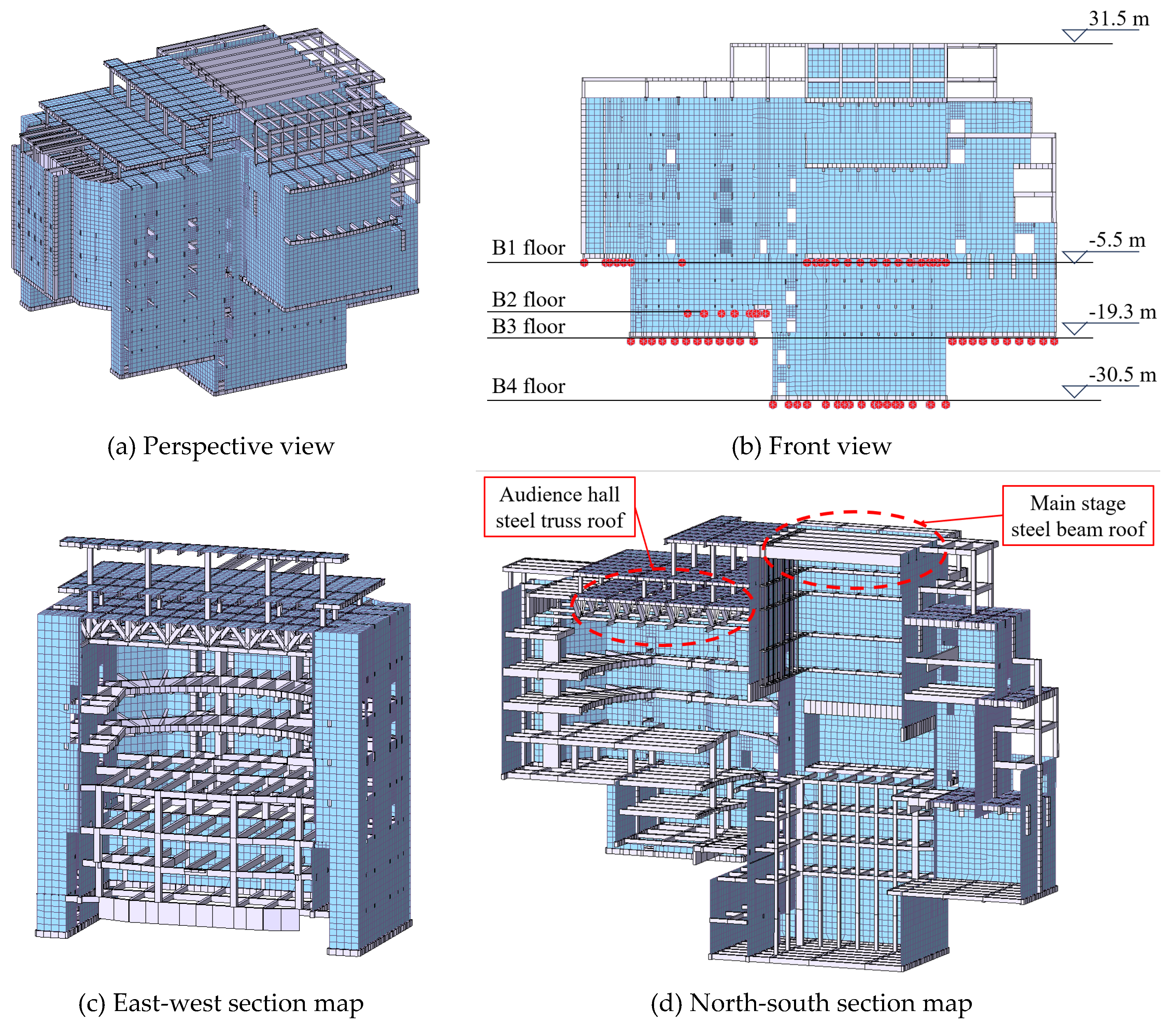
3.1. Analysis Model
3.2. Structural Rocking Response
3.3. Maximum Tension
3.4. Hysteretic Performance of the Bearings
3.5. Structural Acceleration Response
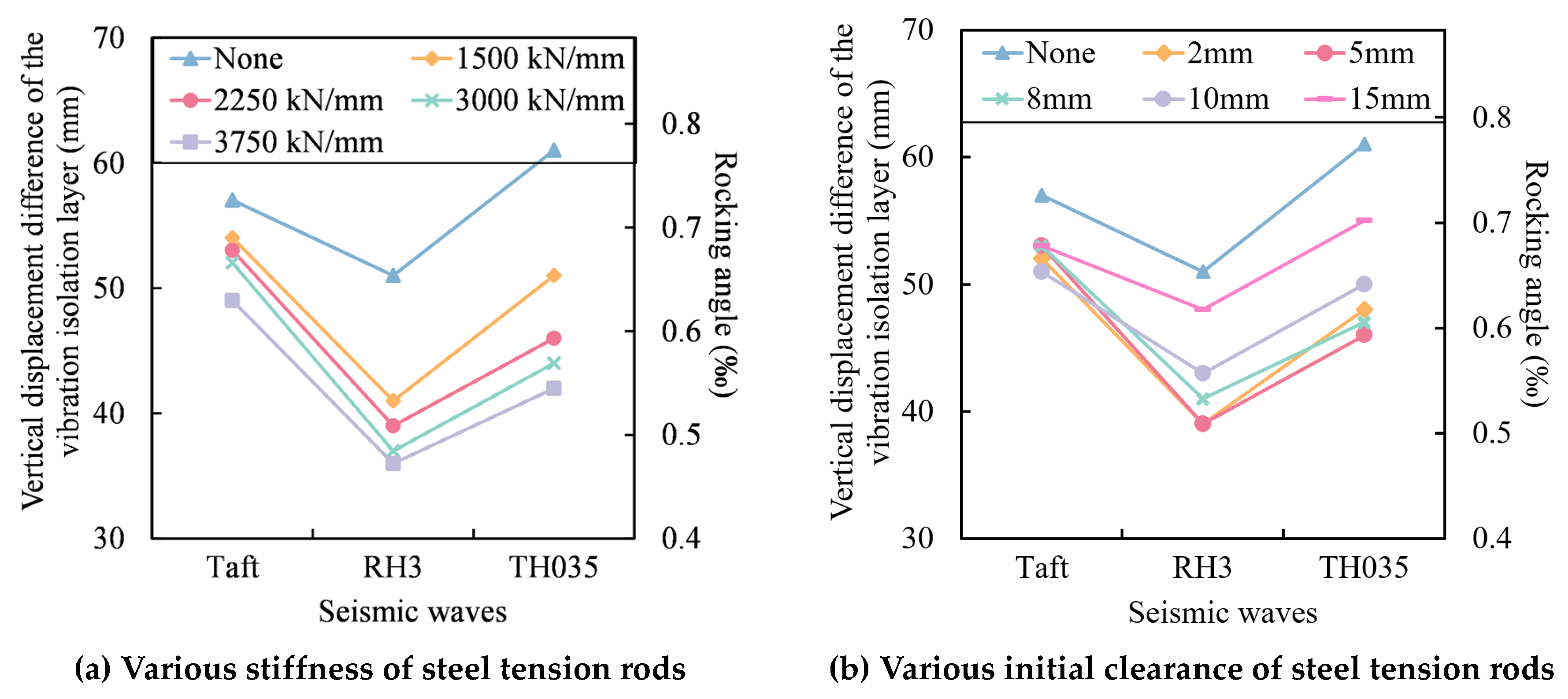
3.6. Selection of Steel Tension Rod Stiffness
4. Finite Element Simulation of Bearing
4.1. Material of Steel Tension Rod
4.2. Finite Element Model
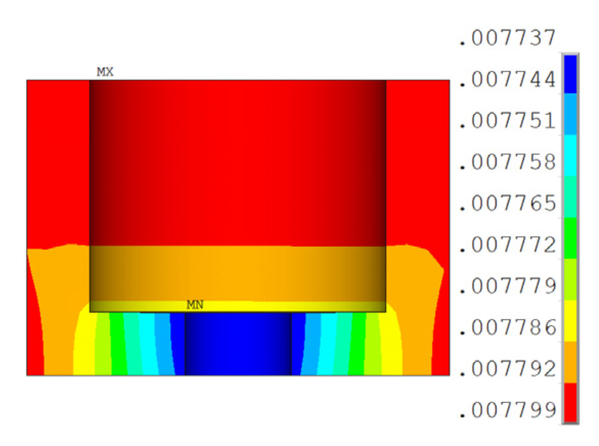
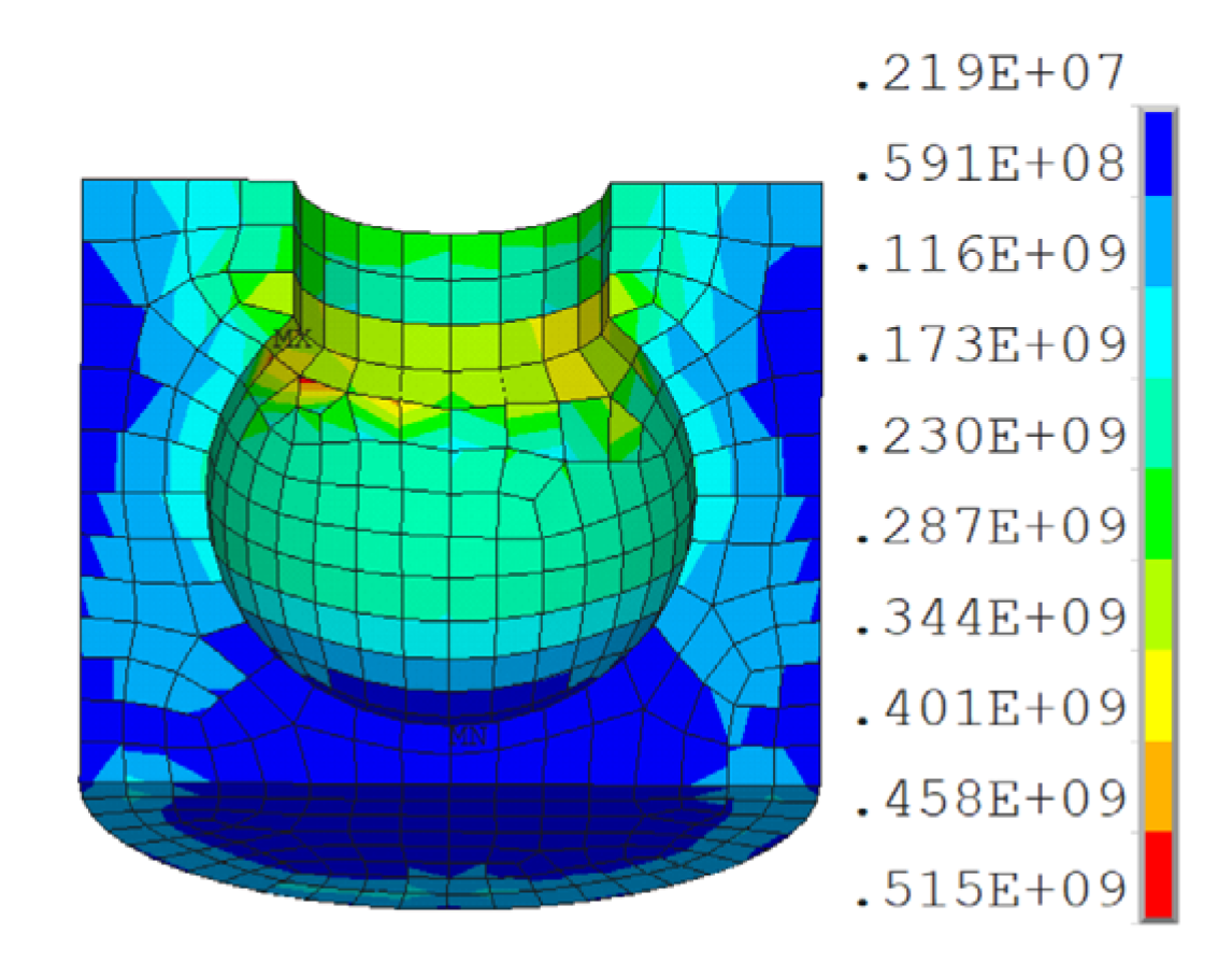
4.3. Modeling Results
5. Conclusions
Funding
References
- Warn, G.P.; Ryan, K.L. A review of seismic isolation for buildings: historical development and research needs. Buildings 2012, 2, 300–325. [Google Scholar] [CrossRef]
- Zhang, C.; Ali, A. The advancement of seismic isolation and energy dissipation mechanisms based on friction. Soil Dynamics and Earthquake Engineering 2021, 146, 106746. [Google Scholar] [CrossRef]
- Zhuang, P.; Zhao, W.; Yang, T.Y. Seismic protection of a single-layer spherical lattice shell structure using a separated three-dimensional isolation system. Soil Dynamics and Earthquake Engineering 2023, 172, 108026. [Google Scholar] [CrossRef]
- Zhuang, P.; Wei, L.; Wang, W.; et al. Feasibility evaluation of pre-pressed spring devices for vertical isolation of single-layer spherical lattice shell structures. Soil Dynamics and Earthquake Engineering 2022, 158, 107308. [Google Scholar] [CrossRef]
- Kim, Y.; Xue, S.; Zhuang, P.; et al. Seismic isolation analysis of FPS bearings in spatial lattice shell structures. Earthquake Engineering and Engineering Vibration 2010, 9, 93–102. [Google Scholar]
- Eltahawy, W.; Ryan, K.L.; Cesmeci, S.; et al. Parameters Affecting Dynamics of Three-Dimensional Seismic Isolation. Journal of Earthquake Engineering 2018, 25, 730–755. [Google Scholar] [CrossRef]
- Politopoulos, I.; Moussallam, N. Horizontal floor response spectra of base-isolated buildings due to vertical excitation. Earthquake Engineering & Structural Dynamics 2012, 41, 587–592. [Google Scholar]
- Pourmasoud, M.M.; Lim, J.B.P.; Hajirasouliha, I.; et al. Multi-directional base isolation system for coupled horizontal and vertical seismic excitations. Journal of Earthquake Engineering 2022, 26, 1145–1170. [Google Scholar] [CrossRef]
- Zhao, Z.; Wang, Y.; Hu, X.; et al. Seismic performance upgrading of containment structures using a negative-stiffness amplification system. Engineering Structures 2022, 262, 114394. [Google Scholar] [CrossRef]
- Liu, W.; Tian, K.; Wei, L.; et al. Earthquake response and isolation effect analysis for separation type three-dimensional isolated structure. Bulletin of Earthquake Engineering 2018, 16, 6335–6364. [Google Scholar] [CrossRef]
- Kageyama, M.; Iba, T.; Somaki, T.; et al. Development of cable reinforced 3-dimensional base isolation air spring. ASME Pressure Vessels and Piping Conference. Vancouver, BC, Canada2002.
- Eltahawy, W.; Ryan, K.; Cesmeci, S.; et al. Displacement/velocity-based control of a liquid spring-MR damper for vertical isolation. Structural Control and Health Monitoring 2019, 26, e2363. [Google Scholar] [CrossRef]
- Cesmeci, S.; Gordaninejad, F.; Ryan, K.L.; et al. A liquid spring–magnetorheological damper system under combined axial and shear loading for three-dimensional seismic isolation of structures. Journal of Intelligent Material Systems and Structures 2018, 29, 3517–3532. [Google Scholar] [CrossRef]
- Chen, Z.; Ding, Y.; Shi, Y.; et al. A vertical isolation device with variable stiffness for long-span spatial structures. Soil Dynamics and Earthquake Engineering 2019, 123, 543–558. [Google Scholar] [CrossRef]
- Xu, H.; He, W.; Zhang, L.; et al. Shaking table test of a novel Three-dimensional seismic isolation system with inclined rubber bearings. Engineering Structures 2023, 293, 116609. [Google Scholar] [CrossRef]
- Dai, K.; Yang, Y.; Li, T.; et al. Seismic analysis of a base-isolated reinforced concrete frame using high damping rubber bearings considering hardening characteristics and bidirectional coupling effect. Structures 2022, 46, 698–712. [Google Scholar] [CrossRef]
- Wu, D.; Xiong, Y.; Yang, Z. Numerical and experimental study of mechanical behaviors of the steel-confined rubber bearing. Construction and Building Materials 2022, 352, 128900. [Google Scholar] [CrossRef]
- Zhang, H.; Liang, X.; Gao, Z.; et al. Seismic performance analysis of a large-scale single-layer lattice dome with a hybrid three-directional seismic isolation system. Engineering Structures 2020, 214, 110627. [Google Scholar] [CrossRef]
- Zhang, C.; Nie, G.; Dai, J.; et al. Seismic isolation research on a double-layer lattice structure using shaking table tests. International Journal of Steel Structures 2019, 19, 1237–1248. [Google Scholar] [CrossRef]
- Han, Q.; Jing, M.; Lu, Y.; et al. Mechanical behaviors of air spring-FPS three-dimensional isolation bearing and isolation performance analysis. Soil Dynamics and Earthquake Engineering 2021, 149, 106872. [Google Scholar] [CrossRef]
- Dong, W.; Shi, Y.; Wang, Q.; et al. Development of a long-period vertical base isolation device with variable stiffness for steel frame structures. Soil Dynamics and Earthquake Engineering 2023, 164, 107638. [Google Scholar] [CrossRef]



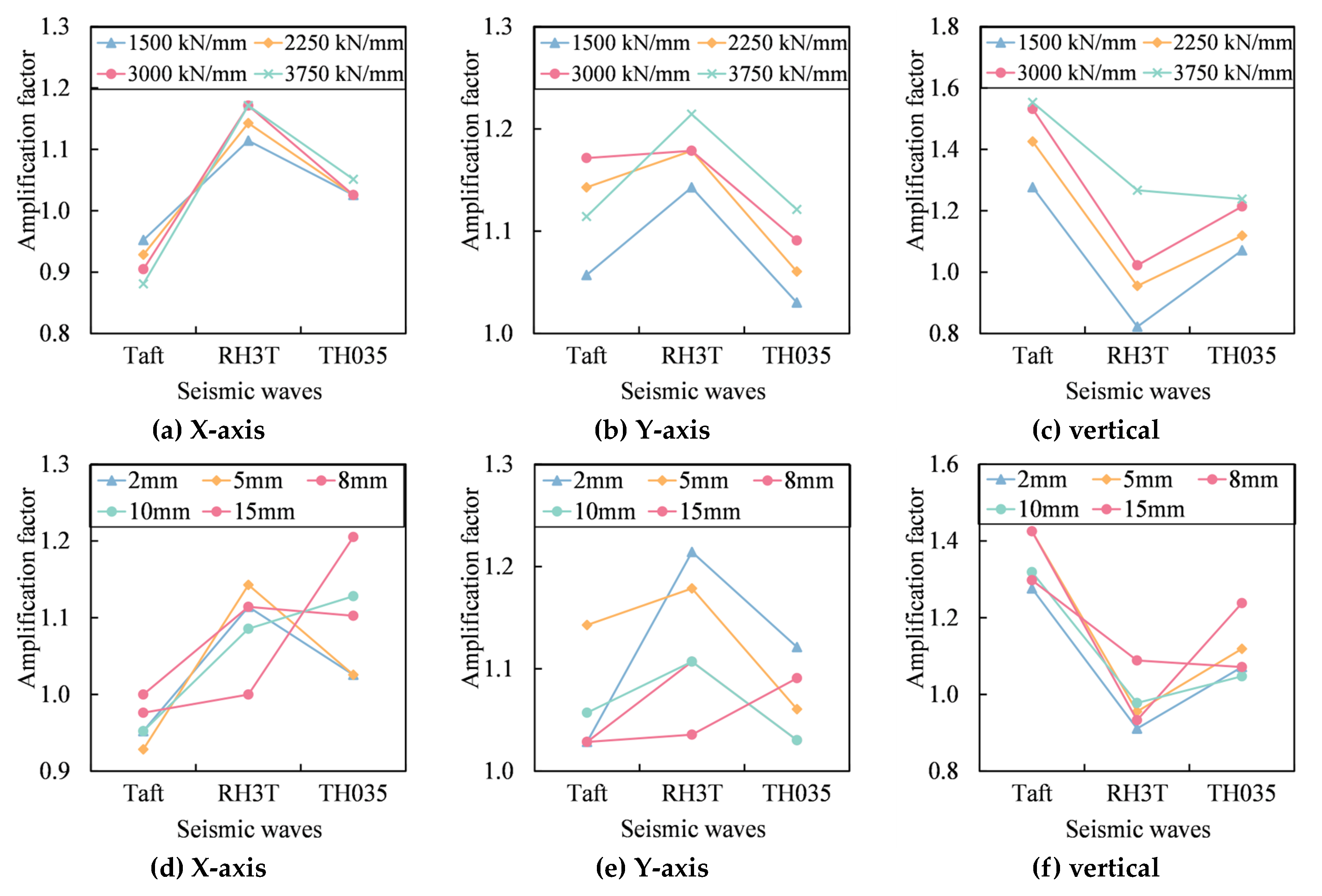
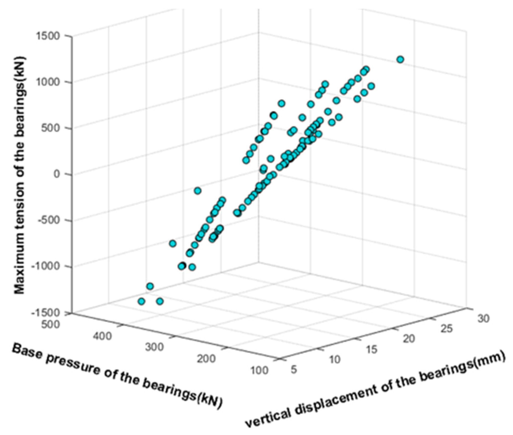
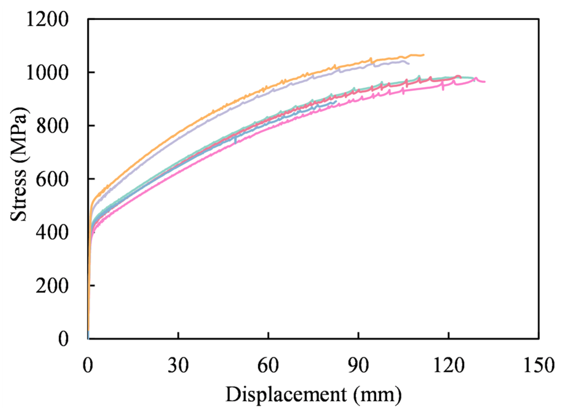
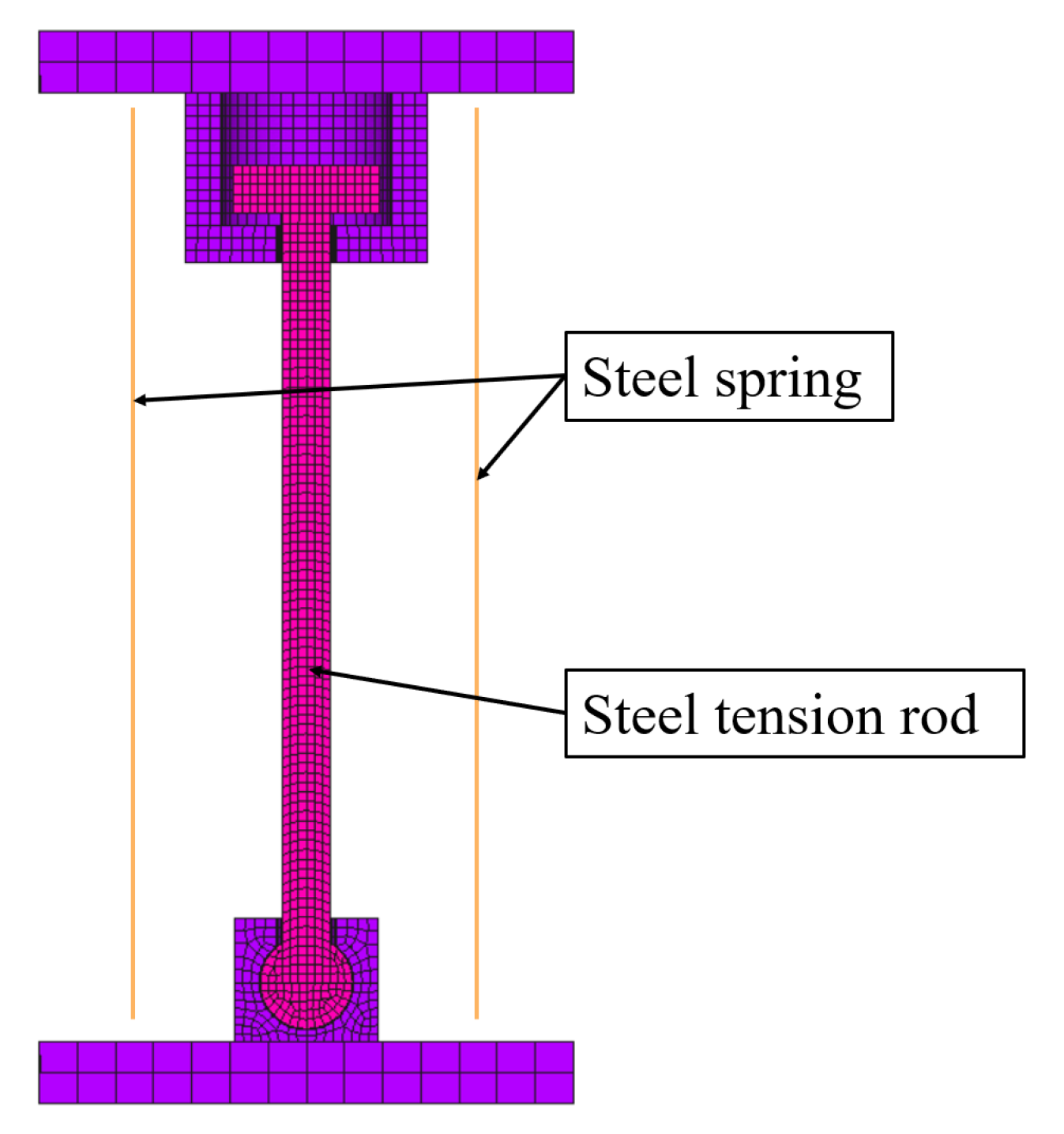

| Cases | Vibration Isolation Bearing Type | Stiffness of steel tension rod /(kN/mm) |
Tonnage of Steel Tension Rod/ton | Initial Clearance of Steel Tension Rod /mm |
|---|---|---|---|---|
| 1-1 | Steel Spring Bearing | - | - | - |
|
2-1 2-2 2-3 2-4 |
New Anti-rocking Bearing | 1500 2250 3000 3750 |
100 150 200 250 |
5 |
|
3-1 3-2 3-3 3-4 3-5 |
New Anti-rocking Bearing | 2250 | 150 | 2 5 8 10 15 |
| Steel category | Steel yield strength/MPa | Ultimate tensile strength/MPa | Elongation after fracture/% | Elastic modulus (GPa) |
Remarks |
|---|---|---|---|---|---|
| Special steel | 438.1 | 994.0 | 67.8 | 195 | Measured value |
| Q235B | 235 | 375~460 | >26 | 206 | Different plate thickness, the performance is different |
Disclaimer/Publisher’s Note: The statements, opinions and data contained in all publications are solely those of the individual author(s) and contributor(s) and not of MDPI and/or the editor(s). MDPI and/or the editor(s) disclaim responsibility for any injury to people or property resulting from any ideas, methods, instructions or products referred to in the content. |
© 2024 by the authors. Licensee MDPI, Basel, Switzerland. This article is an open access article distributed under the terms and conditions of the Creative Commons Attribution (CC BY) license (http://creativecommons.org/licenses/by/4.0/).


