1. Introduction
The family of traditional copper wrought alloys for sliding applications includes a wide range of chemical compositions, including CuNiSi alloys, nickel-aluminium bronze and tin bronze, binary CuZn alloys with and without lead, silicon-brass alloy CuZn31Si1 and special brass alloys [
1]. Many of them have been used for decades without significant changes in their chemical composition and microstructure.
For several reasons, these alloys traditionally are alloyed with far more than 0.1% lead by mass. The lead content ranges from 0.1 to 2 mass-% in special brass alloys (e.g. CuZn37Mn3Al2Pb Si), up to 3.5 mass-% in brass alloys for machining [
2] and even up to 23 mass-% in lead bronze alloys for sliding applications [
3]. As an alternative for these applications a wear resistant layer of tin bronze with PTFE as a solid lubricant can be applied on a different base material, e.g. on aluminium or steel [
4,
5].
For vehicles, the End-of-Life Vehicles Directive 2000/53/EU restricts the use of hazardous substances such as lead. Although the End-of-Life Vehicles Directive 2000/53/EU still defines exemptions for restricted substances such as lead, no one can be sure that the exemptions will never end. In this context the European Commission (EC) also began setting limits for dangerous substances such as cadmium, mercury and lead around 2000 [
6]. In 2018, the European Commission approved the decision to classify lead as toxic to reproduction [
7]. After that, the development of new lead-free alloys for sliding applications accelerated substantially.
The latest development in hazardous substances regulation is a proposal to ban the use of PFAS. The result of this would be that an important solid lubricant would also be banned from sliding materials.
Based on the developments described above, it is not surprising that copper alloy manufacturers and consumers are becoming increasingly active in developing and validating alternative lead-free copper alloys (e.g. see [
8]).
2. Trends and Development of New Copper Alloys for Sliding Applications
In general, there are two ways to develop new lead-free copper alloys for sliding applications. On the one hand, the inventor can start from an existing alloy and improve them through iterative steps of chemical and processing measures. An example is the alloy CuZn31Si1, which originally contained 0.3 to 0.8% lead by mass. With the only goal to be lead-free, the lead content could be limited to a maximum of 0.1% by mass. But the absence of lead not only deteriorates the machinability of CuZn31Si1 but does not contribute to improve the modest load capacity of the alloy either. Consequently, further improvements of CuZn31Si1 aim to increase its wear resistance by alloying certain amounts of manganese and silicon. Likewise, the wear resistance of special brass alloys of type CW713R can be improved by varying the Al, Mn, Ni and Si content (e.g. see [
9]).
On the other hand, the invention of new alloys can be based on completely new concepts. As an example, it has been possible to use new Cu-Al-Mn-Zn-alloys to replace nickel silver in sliding applications [
10]. The newest trend are high entropy alloys which go completely beyond existing copper alloy families. This concept is are also being considered for innovative alloys in sliding applications [
11].
3. Overview on Recent Copper Materials for Sliding Applications
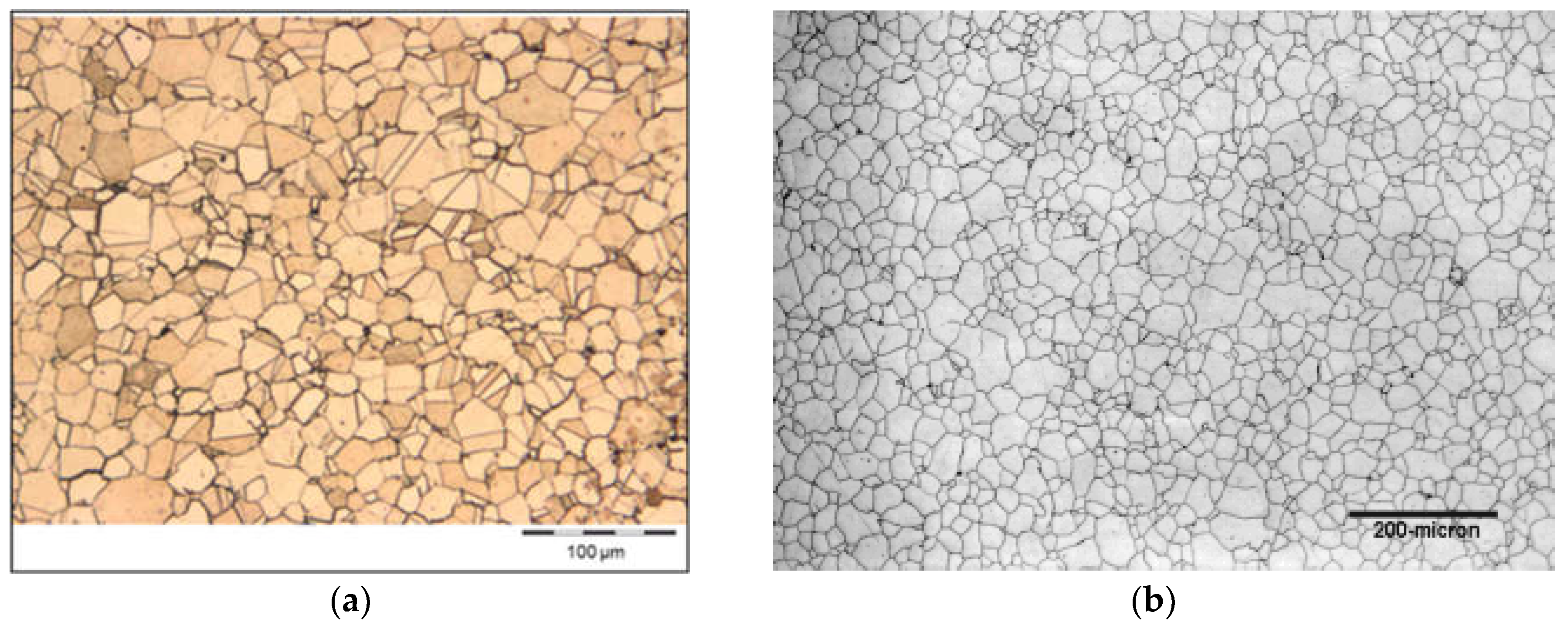
The family of existing standardized wrought alloys for sliding applications includes several bronze and brass respectively special brass alloys. Typical bronze alloys for this are CuNi2Si, CuNiSn-alloys (e.g. CuNi6Sn6 and CuNi15Sn8), CuSn8 / CuSn8P and CuAl10Ni5Fe4. All of these bronze alloys have a high proportion of alpha phase and alloying elements such as aluminium, nickel or tin. That leads to good mechanical wear resistance, quite high temperature stability and good corrosion resistance. The mechanical strength and fatigue strength depend heavily on the work hardening state of these alloys and can therefore be increased significantly by cold forming [
12]. Further properties relate to individual bronze alloys. In the case of CuNi2Si, the specific properties are a combination of excellent mechanical properties with good electrical and thermal conductivity [
13]. Another example is tin in CuSn8/CuSn8P. The formation of tin oxide layers in frictional contact promotes the good friction and wear properties of this alloy [
14].
Figure 1.
Typical micrographs of different bronze alloys for sliding applications: (a) CuNi2Si; (b) CuNi15Sn8; (c) CuSn8P; (d) CuAl10Ni5Fe4.
Figure 1.
Typical micrographs of different bronze alloys for sliding applications: (a) CuNi2Si; (b) CuNi15Sn8; (c) CuSn8P; (d) CuAl10Ni5Fe4.
Typical standardized brass alloys for sliding applications with very low loadings are CuZn40/CuZn42 respectively CuZn39Pb3/CuZn40Pb2 [
12]. The microstructures of CuZn40 and CuZn39Pb3 consist of a pure β/α matrix and are free of any hard phases that could protect against wear. That is the reason why such alloys are only used for very moderate loads. CuZn39Pb3 and CuZn40Pb2 are obviously lead-alloyed, but traditionally also CuZn40/CuZn42 contain more than 0.1 mass-% lead for improvement of machinability.
CuZn31Si1 alloys (both lead-alloyed and lead-free, silicon brass) are used as standard for low to medium load sliding applications [
12]. These silicon brasses have a structure consisting predominantly of α-brass phase with a smaller proportion of β-brass phase, which is aligned in the direction of hot deformation. Compared to the α phase, the β phase contributes more to the wear resistance of this alloy. Silicon in this alloy is kept in solid solution.
When brass alloys with increased wear resistance are required, normally special brass alloys such as CuZn37Mn3Al2PbSi are chosen [
12]. Using the variation of the chemical composition, the resulting zinc equivalent and the temperature treatment of the materials, the brass matrix in such alloys can be adjusted from predominantly α phase to a mixture of α and β phases to pure β phase. In the brass alloys, a higher content of β-phase already leads to a better wear resistance, but the main effect is achieved by the hard phase particles (usually silicides with a length of a few µm to a maximum of several 100 µm) which are distributed homogeneously within the brass matrix to protect the softer brass matrix from wear.
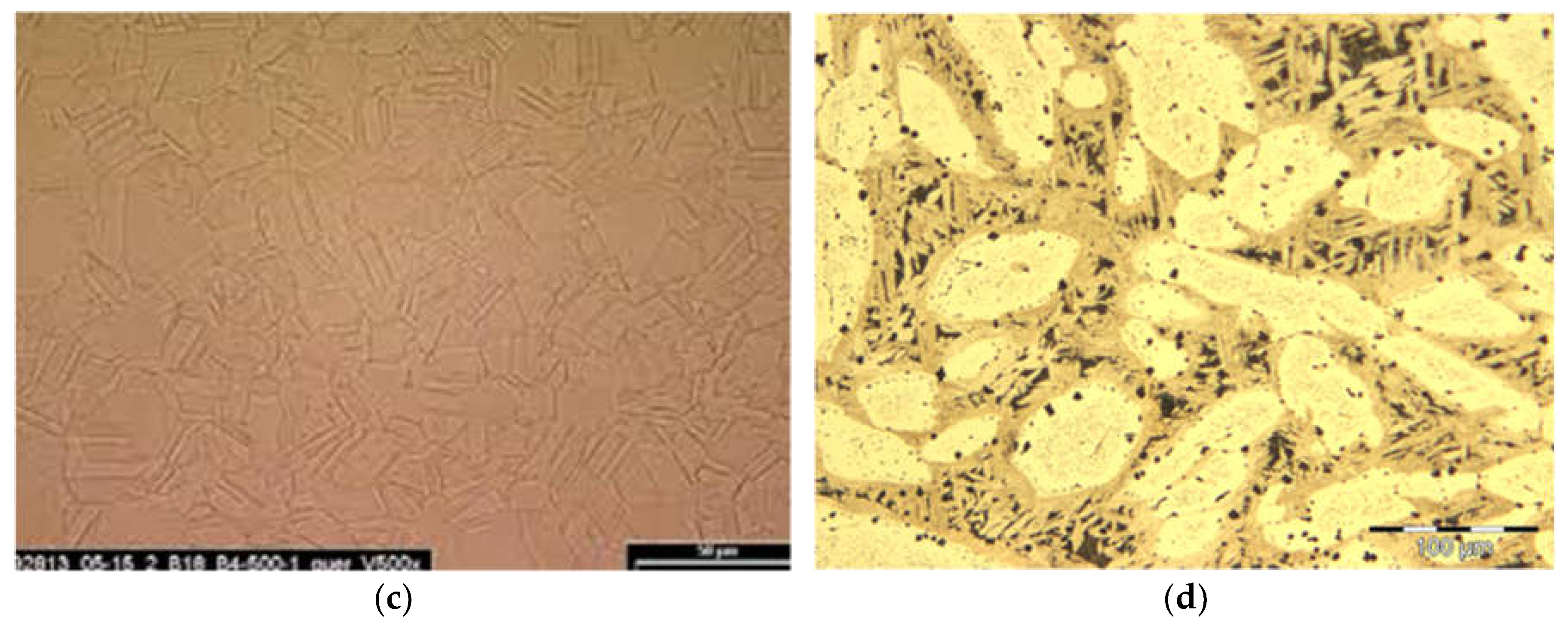
Figure 2.
Typical micrographs of different brass alloys for sliding applications: (a) CuZn40Pb2; (b) CuZn31Si1; (c) CuZn37Mn3Al2PbSi.
Figure 2.
Typical micrographs of different brass alloys for sliding applications: (a) CuZn40Pb2; (b) CuZn31Si1; (c) CuZn37Mn3Al2PbSi.
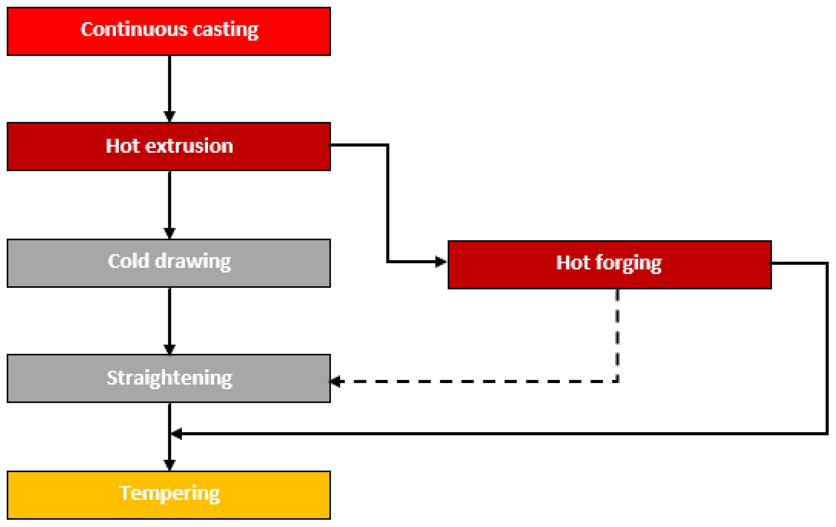
Finally, the alloy composition and α/β-phase mixture also have a strong effect on the production process for manufacturing the semi-finished parts for the sliding applications (
Figure 3) [
15]. In the hot extrusion and hot forging process, a high β content helps reduce hot forming resistance. For cold forming steps such as cold drawing and straightening of bars, tubes or forgings, cold stamping or flanging a higher α-phase content facilitates the forming process.
To combine all these benefits the concept for the new alloy was to have sufficient β-phase for a good hot formability during extrusion at about 900°C while the β-phase should be transformed to α-phase when the alloy is cooled down to room temperatures after that. The α-phase is needed to support the cold drawing and straightening that follows after hot extrusion.
4. CuAl8Fe5Ni4Zn4Sn1 as a New Lead-Free Copper Alloy for Sliding Applications
This new alloy is the new multi-component bronze alloy with the short name CuAl8Fe5Ni4Zn4Sn1. In this publication, the progress in the further development of the alloy is presented. Compared to the first publication in 2020 [
16] a much deeper understanding of the strengthening mechanisms of the new alloy was achieved and will be subject of this publication.
The chemical composition (
Table 1) differs from any conventional family of standardized bronze alloys. The basic idea designing the new alloy was to combine the positive effects of the alloying strategy of other bronze alloys such as aluminium bronze, tin bronze and those of CuZn gliding metal. The copper content of CuAl8Fe5Ni4Zn4Sn1 is at least 75 mass-% and the sum of all alloying elements is in the range of 17 to 25 mass-%. With the chosen combination of aluminium, zinc and tin as alloying elements stable tribolyers for improvement of load capacity are achieved [
17,
18]. An additional advantage of this alloy is to be technically lead-free (maximum 0.1 mass-% lead).
The microstructures of CuAl8Fe5Ni4Zn4Sn1 after complete manufacturing including continuous casting, hot extrusion, cold drawing and tempering consist of a homogeneous α-brass matrix in which numerous fine and individual coarser intermetallic κ-phases are embedded (
Figure 4).
According to the various physical, mechanical and technological requirements for the new alloy CuAl 8Fe5Ni4Zn4Sn1 the following characteristic mechanical properties were identified for the pre-material for plain radial bearings which are given in
Table 2 and can also be found in the first publication [
16] and in the material data sheet [
19].
After this general information the publication proceeds to the principal argument and focuses on the strengthening mechanisms by which the excellent properties of the new alloy are achieved.
5. Strengthening Mechanisms of CuAl8Fe5Ni4Zn4Sn1
5.1. Initial Condition after Continuous Casting
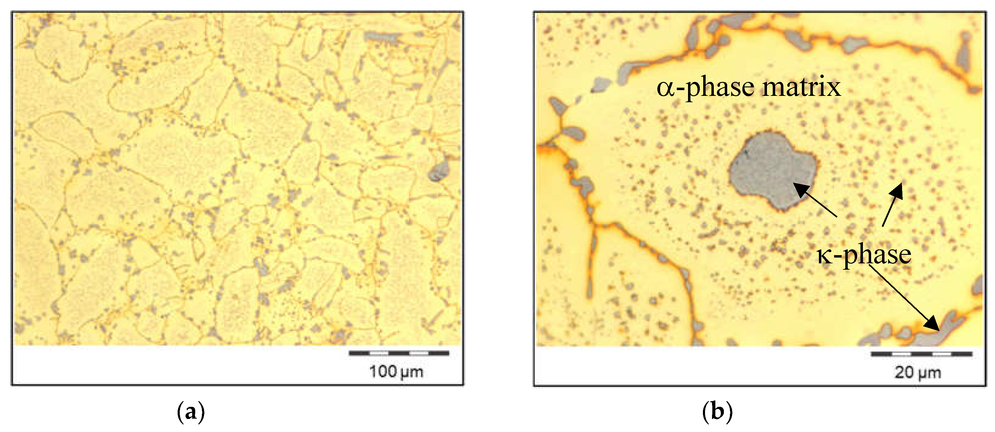
Continuous casting is the first production step in the manufacturing route of OF 2238 pre-material tubes (bigger diameter) respectively rods (smaller diameter) for bushings. Choosing the right casting parameters e.g. in terms of casting temperature and casting speed, these bars already provide very fine-grained and homogeneous microstructures. of α-matrix phase. Only near the outer surface these grains are elongated. The rest of the cross section consists of fine globular matrix grains. In the interior and on the grain boundaries of the α-grains, κ-phase precipitations are present. The distribution of the κ-phase is nearly homogeneous (
Figure 5).
These microstructures are different compared to the dendritic morphology typically found in other bronze alloys such as tin bronze or the standard nickel-aluminium bronze. This is caused by several reasons:
CuAl8Fe5Ni4Zn4Sn1 is a polymorph alloy with β-phase during solidification, which transforms into α- and κ-phases during cooling to room temperature. In such an alloy the solid-solid phase transformation during cooling after solidification has an additional impact on grain refinement. This is because from each mother grain there can result a plurality of daughter grains. The same behaviour can be observed in other polymorph copper alloys such as α/β brass [
15].
The iron content further contributes to the refinement of the microstructures. This effect is related to the iron, which is in solid solution in the copper matrix, as this proportion supports nucleation [
20].
The forementioned aspects count for other bronze alloys such as CuAl10Ni5Fe4 as well. Notwithstanding that, as-cast CuAl10Ni5Fe4 provides also fine grains, but a dendritic grain morphology. In comparison, CuAl8Fe5Ni4Zn4Sn1 does not only provide fine, but also globular microstructures. Therefore, further differences in the chemical compositions must be the reason for the globular microstructures of CuAl8Fe5Ni4Zn4Sn1;
Most likely, the globular microstructures of CuAl8Fe5Ni4Zn4Sn1 can be explained by the effect of tin which is reported to shift the grain morphology of aluminium bronze to globulitic. This is due to the decline in nucleation temperatures, the reduction in undercooling intensity, and the decrease in cooling rate during solidification [
21].
To conclude this paragraph, the fine and globular microstructures of the alloys are the result of solidification behaviour, phase transformations and nucleation effects. To start already with fine casting microstructures is beneficial for promoting fine microstructures also in the finished wrought alloy product and therefore already in the first production step provides to the strength of the raw material bars.
5.2. Hot Extrusion of Tubes
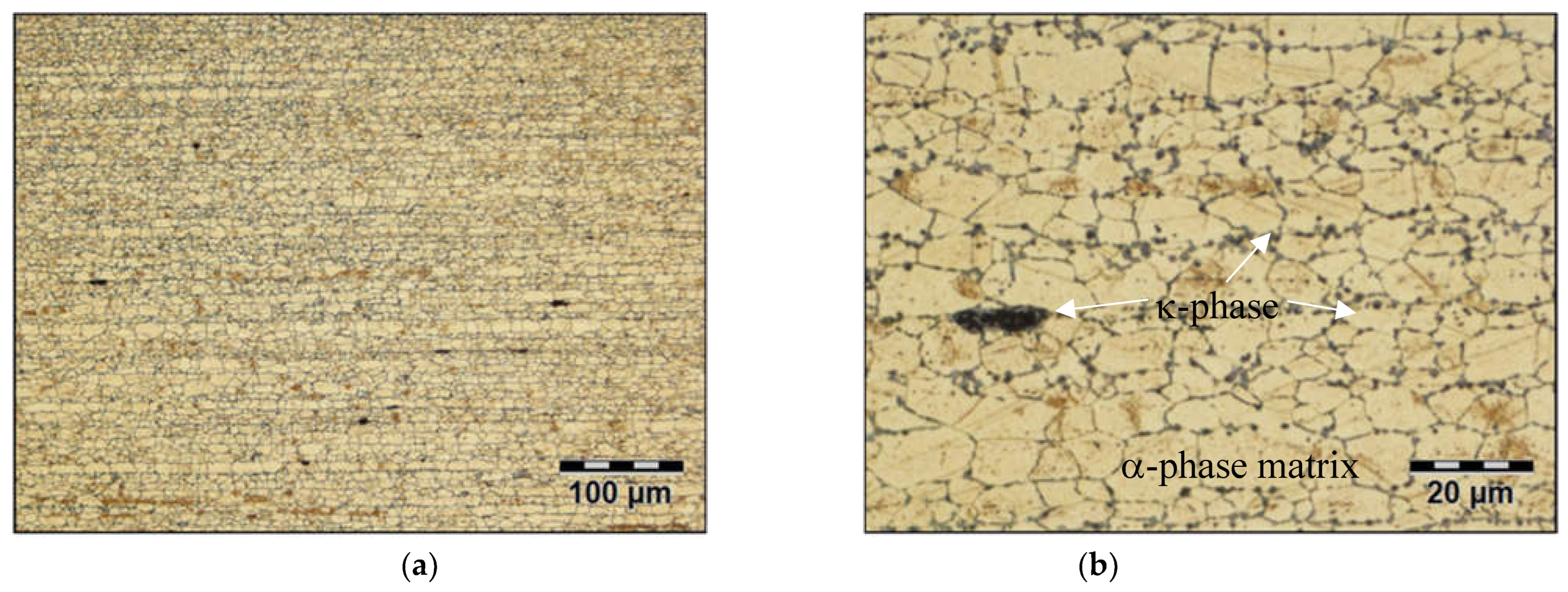
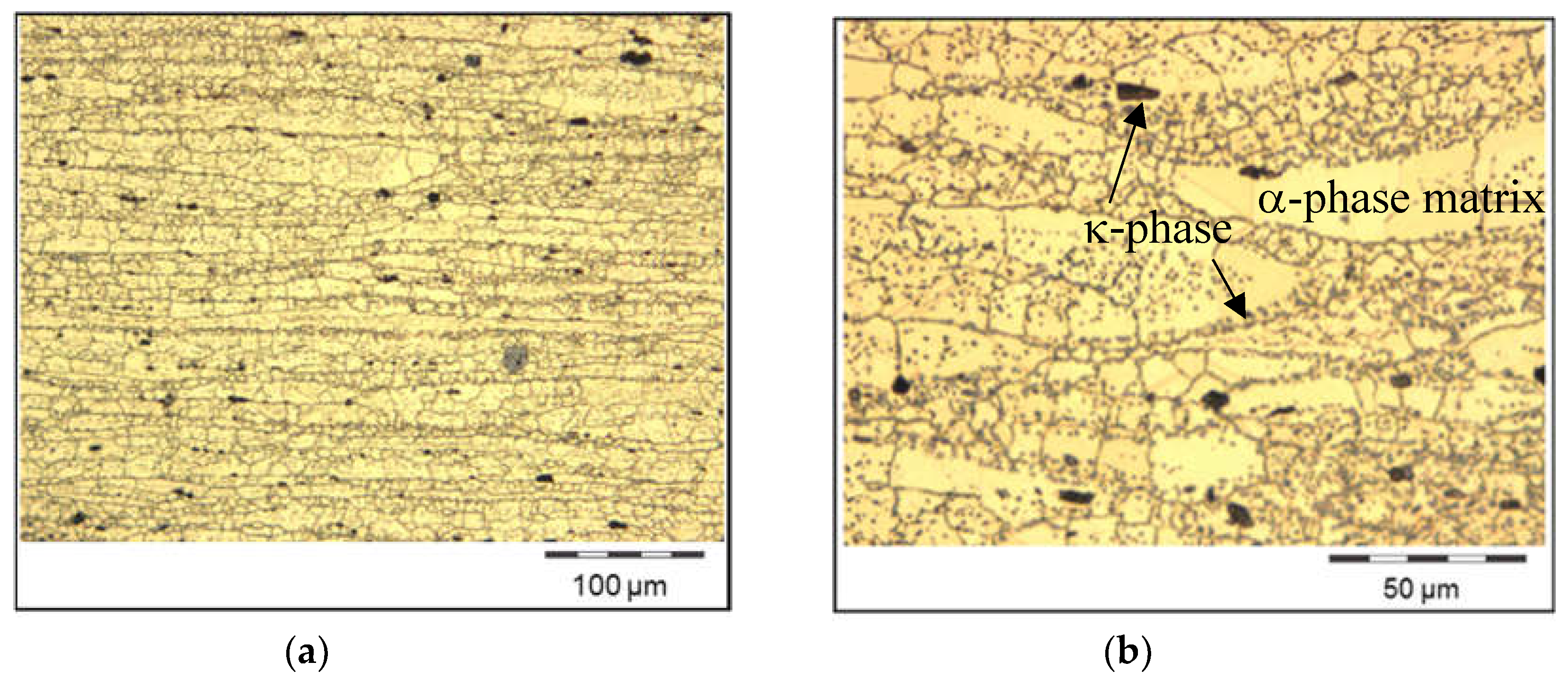
Dynamic recrystallisation during hot extrusion leads to homogenisation and additional refinement of the microstructures from casting. After hot extrusion, the microstructures consist of an α-phase matrix with κ-phase precipitations, the latter with a size of several microns. The grains are elongated longitudinally in the extrusion direction, while the grain size in radial direction is diminished (
Figure 6). This decrease is the main reason for the increased strength after hot extrusion (Hall-Petch relationship).
Another strengthening mechanism comes from work hardening during hot extrusion. So there are two mechanisms that result in a higher strength of the extruded product compared to the cast billet.
5.3. Effect of Cold Drawing and Straightening of the Extruded Tubes
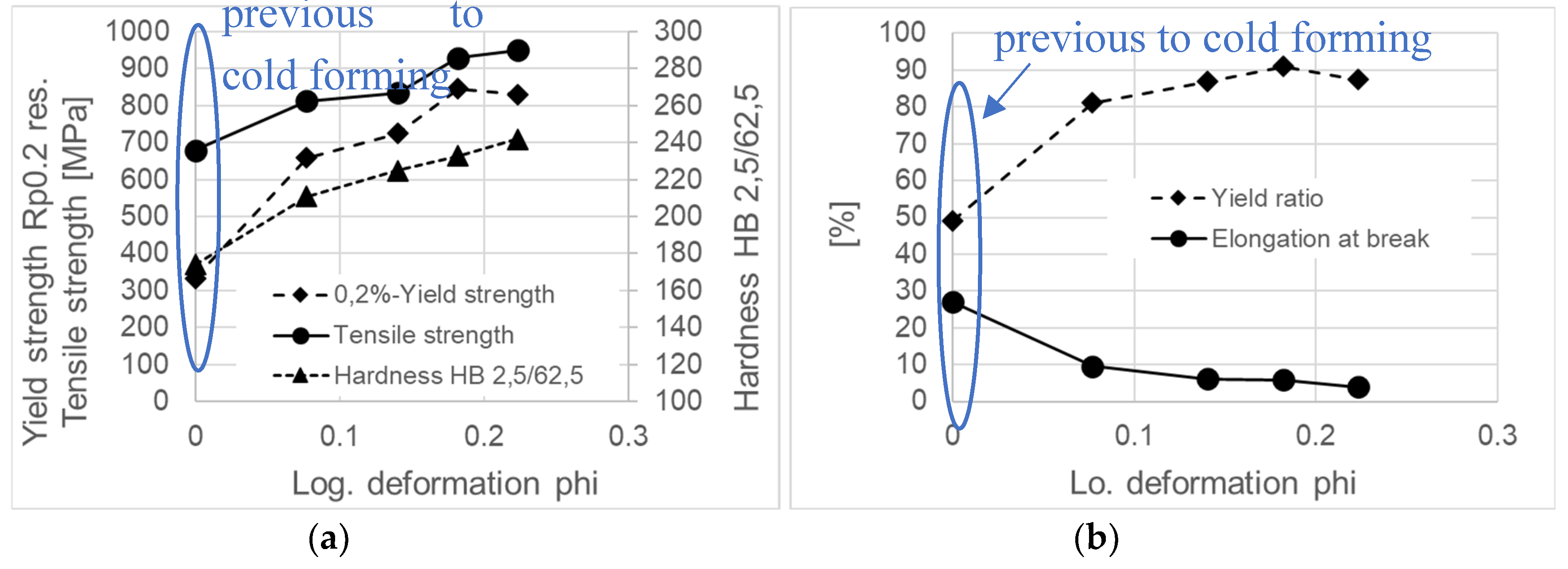
After hot extrusion, the tubes are cold drawn and straightened both for dimensional reasons (increasing straightness and reducing diameter tolerance) and to increase mechanical strength. The cold strengthening effect is shown in
Figure 7.
Similar to nickel alloys and austenitic steels also in this new bronze alloy the deformation of the fcc lattice of the α-phase generates substantial work hardening. The work hardening effect is enhanced by aluminium, tin and zinc which are in solid solution [
12]. By this, CuAl8Fe5Ni4Zn4Sn1 achieves in the cold drawn condition strength values similar or even higher than typically known for other bronze alloys such as CuAl10Ni5Fe4 [
22].
5.4. Thermal Treatment after Cold Drawing of CuAl8Fe5Ni4Zn4Sn1
The deformation in the cross section during cold drawing is inhomogeneous. Main reasons are the friction between tool surface and the tube material, heating and local differences of the stress state.
Due to the friction between the tool surface and the tube material there occurs shear deformation in the near surface zones of the tube material;
Furthermore, being surrounded by the neighbouring material in all directions this results in a triaxial stress state of the core, but the stress state near the tube surface is nearly plain;
Bothe forementioned friction and adiabatic heating leads to increasing temperatures in the tube material. Therefore, also the temperature distribution in the tube cross section is inhomogeneous.
After cold drawing most of these stresses remain in the material [
23,
24]. But depending on the type (tensile or compressive) and magnitude, residual stresses can subsequently have a negative impact on the processing and use of the tubes (distortion, stress cracking, relaxation, Bauschinger effect, to name just a few examples). Thus they must be reduced, which is achieved for CuAl8Fe5Ni4Zn4Sn1 by tempering with air cooling.
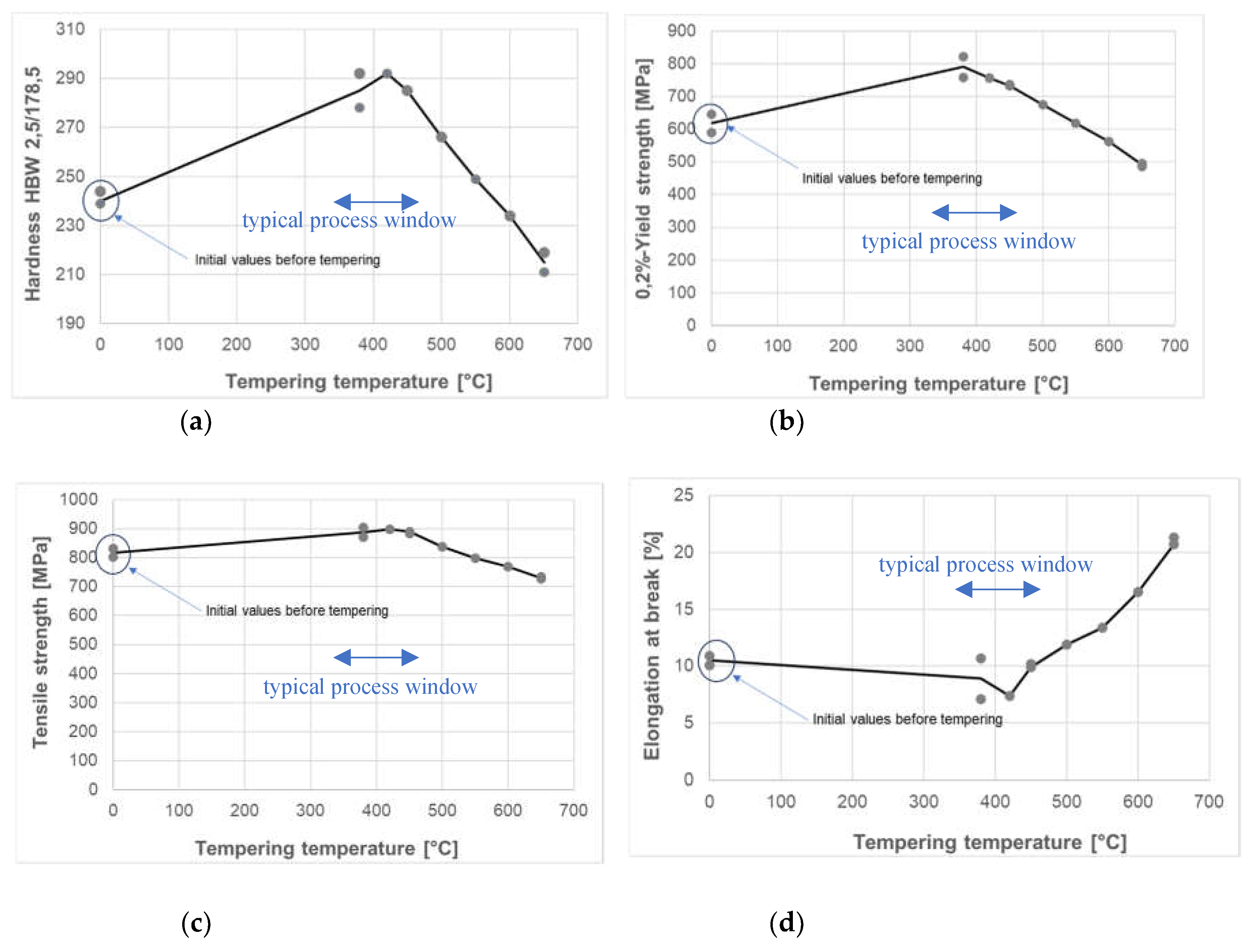
Typically, the tempering temperature for aluminium bronze alloys is between 350 and 650 degrees Celsius. This range was also covered in the tempering tests of CuAl8Fe5Ni4Zn4Sn1 (
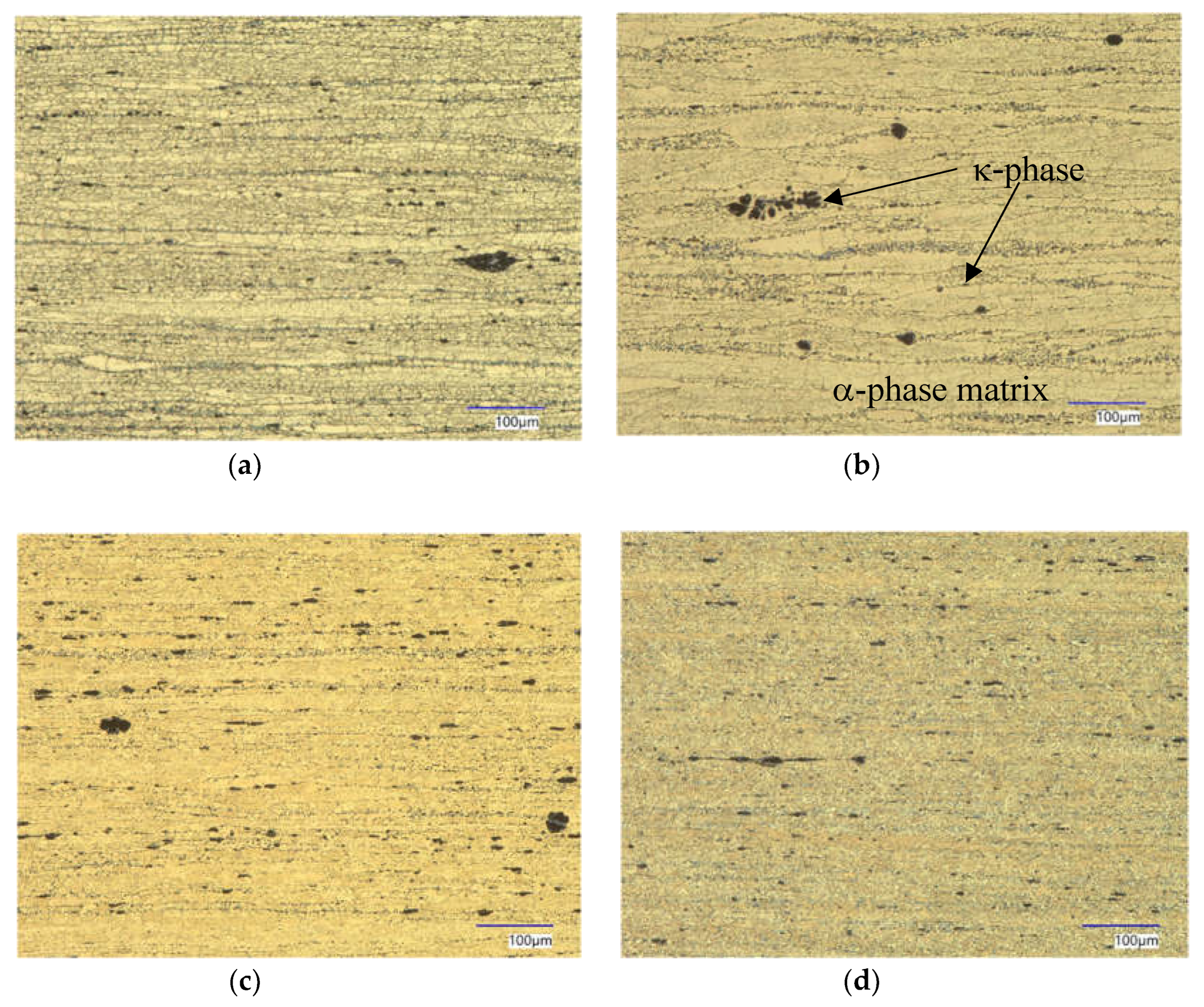
Figure 8). Considering the light optical micrographs there is found no significant effect on the microstructures after different tempering temperatures (
Figure 9).
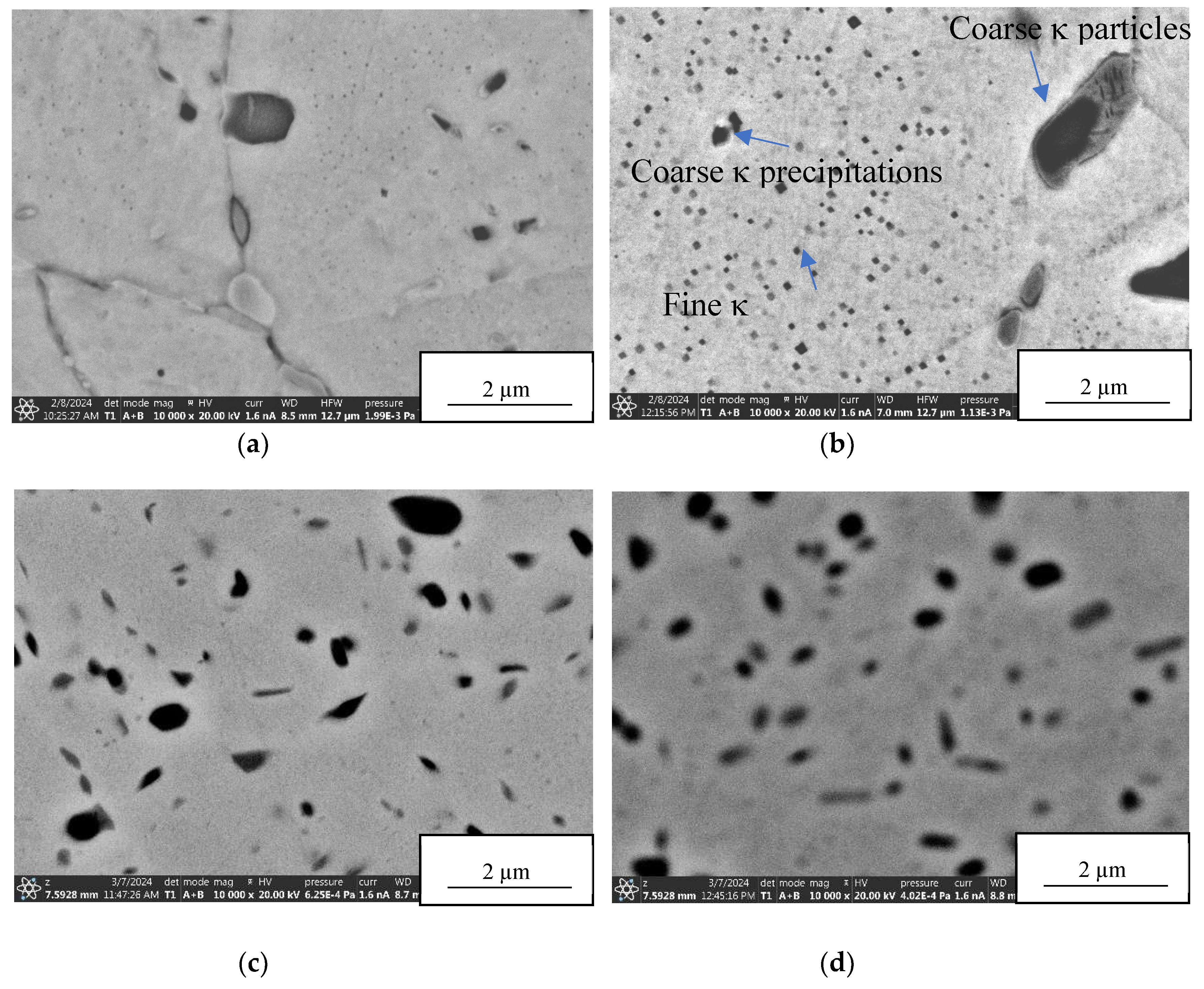
But the tempering tests had an unexpected result. It can be seen from the diagram that the new alloy provides age hardening. In other aluminium bronze alloys age hardening is only achieved if the material has undergone a solutionizing process previously. For CuAl8Fe5Ni4Zn4Sn1, the age hardening of the alloy can be carried out without this heating process and yet the increase in strength is at least similar or even higher than with solution-annealed CuAl10Ni5Fe4. In order to find the reason for this effect the material has been analysed by surface electron microscopy (
Figure 10).
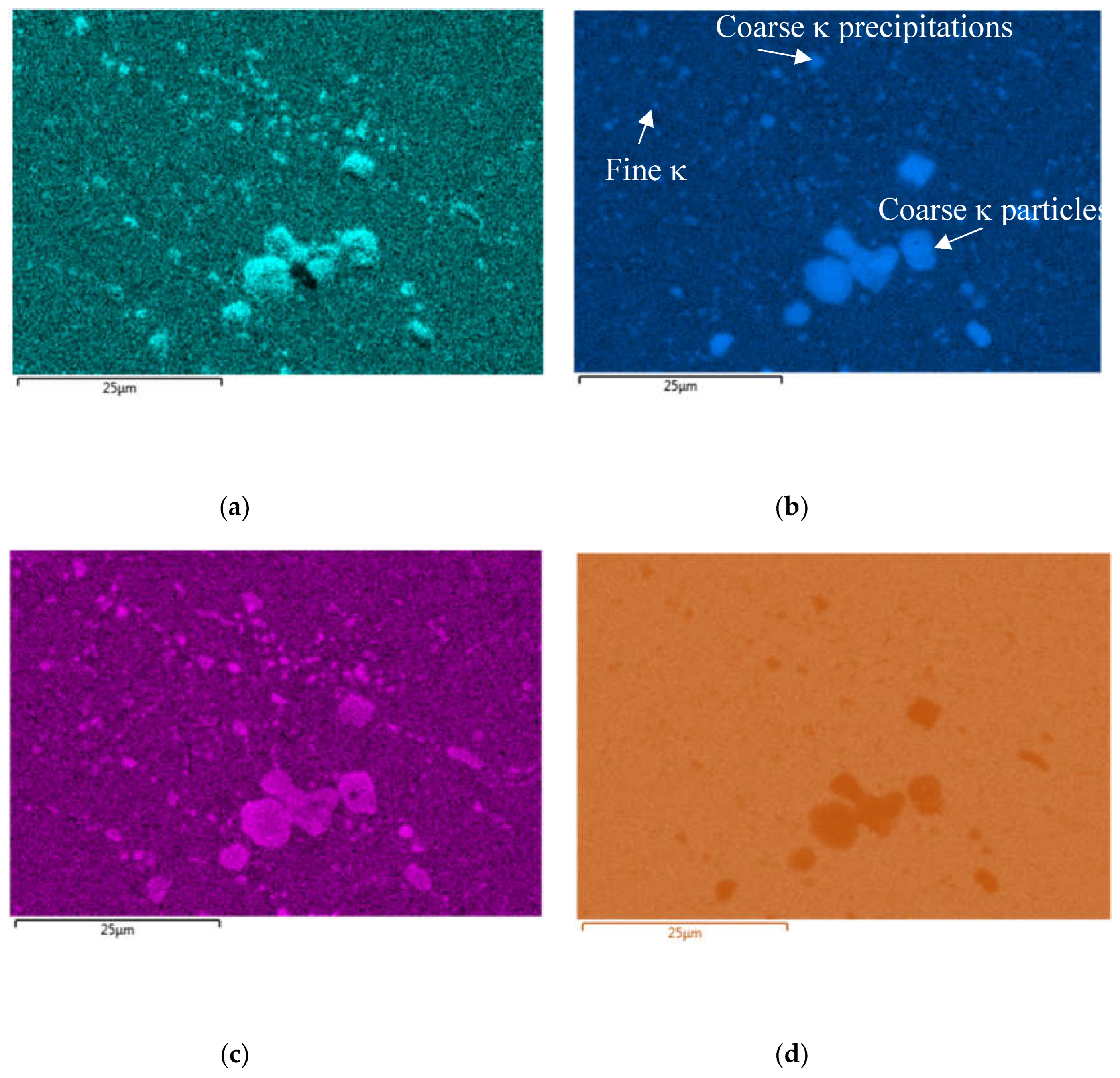
Both coarse and fine precipitations (κ-phases) can be seen and were analysed using EDX mapping (
Figure 11) and point analysis. As shown in
Table 3 coarse particles are of Fe
3Al type but because of their size of several microns have only little relevance for the strengthening of the material. The size of the fine particles ranges from about 20 to 100 nm and they are of the Fe
3Al, NiAl and Al
3Ni
5-type. With this it is demonstrated that fine κ-phase precipitations are the reason for such strong age hardening in the new alloy.
6. Summary
CuAl8Fe5Ni4Zn4Sn1 is a new copper base alloy for plain bearing bushings where high strength is required. The bushing manufacturing route begins with continuous casting of bars for billets. The following process steps are hot extrusion, cold drawing, straightening and tempering. The authors have shown how the entire manufacturing process contributes to obtain a material with a combination of high strength, ductility and sufficient toughness. Starting with fine microstructures after casting, homogenisation and refinement occurs during hot extrusion. Some work hardening effects are related to hot forming and particularly cold drawing.
But the most unexpected impact on material strength was achieved by tempering the cold formed tubes. Without previous solutionizing there is a strong hardening effect in the new alloy by precipitation formation of κ-phase at temperatures of about 400°C and air cooling.
It can be stated that the new chemistry of CuAl8Fe5Ni4Zn4Sn1 with the chosen amounts of Sn, Fe and Ni together with a carefully designed production process leads to a big advantage in comparison with other aluminium bronze alloys like CuAl10Ni5Fe4 or others. Neither solutionizing prior to age hardening nor quenching is necessary to get these excellent results.
7. Outlook
Copper alloys, that were developed long before, have been used for many years. The situation changed when the banishment of lead from these alloys spurred the development of new copper alloys. As can be seen from the development of CuAl8Fe5Ni4Zn4Sn1 [
24], the new copper alloys are a serious alternative to the existing standard alloys. This new development makes clear, that there are many alloy combinations still unexplored that possibly would display further unexpected benefits.
Funding
This research received no external funding.
Conflicts of Interest
The authors declare no conflict of interest.
References
- Arens, J.; Bungardt, W.; Mann, H.; Martin, E.; Meboldt, W.; Meysenbug, C.M.; Thum, A.; Weber, R.; Wiemer, H.; Kühnel, R. Werkstoffe für Gleitlager; Springer-Verlag OHG, Berlin / Göttingen / Heidelberg, 1952; pp. 233–318.
- Deutsches Kupferinstitut. Kupfer-Zink-Legierungen (Messing und Sondermessing). Available online: https://kupfer.de/wp-content/uploads/2019/09/i5.pdf (08-03-2024).
- Dinesh, D.; Megalingam, A. Dry Sliding Friction and Wear Behaviour of Leaded Tin bronze for Bearing and Bushing Application. Arch. Metall. Mater. 2021, 66, 1095–1104. [Google Scholar] [CrossRef]
- Bartz, W.J. Selbstschmierende und wartungsfreie Gleitlager. Typen, Eigenschaften, Einsatzgrenzen und Anwendungen; Expert-Verlag, Tübingen, 1993.
- Jose, J.P.; Thomas, S.; Kuruvilla, J.; Malhotra, S.K.; Goda, K.; Sreekala, M.S. Advances in polymer composites: Macro- and microcomposites—State of the art, new challenges, and opportunities. In Polymer Composites; Wiley: Weinheim, Germany, 2012; Volume 1, pp. 3–16. [Google Scholar]
- DIRECTIVE 2002/95/EC OF THE EUROPEAN PARLIAMENT AND OF THE COUNCIL of 27 January 2003 on the restriction of the use of certain hazardous substances in electrical and electronic equipment.
- Availabe online: https://echa.europa.eu/documents/10162/61ac8d81-6ea2-6ad0-ffef-95037c9182ce (11-03-2024).
- Reetz, B.; Münch, T. Challenges for novel lead-free alloys in hydraulics. 12th International Fluid Power Conference: Dresden, 2020. Availabe online: https://tud.qucosa.de/api/qucosa%3A71055/attachment/ATT-0/ (11-03-2024).
- OTTO FUCHS Dülken Material Data Sheets: Alloy OF 2228.
- Jitchoom, S.; Rojananan, S.; Rojananan, S. Influence of Aluminium on the Color, Microstructure and Hardness of White Alloys. Advanced Materials Research 2013, 802, 159–163. [Google Scholar] [CrossRef]
- Kumar, D. Recent advances in tribology of high entropy alloys: A critical review. Progress in Materials Science 2023, 136. [Google Scholar] [CrossRef]
- Dies, K. Kupfer und Kupferlegierungen in der Technik; Springer-Verlag Berlin / Göttingen / Heidelberg, 1967.
- Shalunov, E.; Shalunov, S.; Vladimirova, Y. Analysis of operating conditions of heavy-loaded and heat-stressed friction units of powerful internal combustion engines and development of copper nanocomposite powder materials for them. MATEC Web of Conferences 298 (2019). Available online: https://www.matec-conferences.org/articles/matecconf/pdf/2019/47/matecconf_icmtmte18_00101.pdf (11-03-2024).
- Collini, L. Copper Alloys - Early Applications and Current Performance-Enhancing Processes; InTech, Croatia, 2012 . Available online: http://www.issp.ac.ru/ebooks/books/open/Copper_Alloys_-_Early_Applications_and_Current_Performance_-_Enhancing_Processes.pdf (11-03-2024).
- Reetz, B. Mikrostruktur und Eigenschaften stranggepresster sowie kaltverformter Messinglegierungen; Dissertation, Cuvillier-Verlag, Göttingen, 2006.
- Reetz, B.; Münch, T. Neue bleifreie Aluminiumbronze für Pleuellager - Anwendungspotential von komplexen Mehrstoffbronzen. Metall 2020, 11, 431–436. [Google Scholar]
- Paulus, A. Tribolayer Formation on Bronze CuSn12Ni2 in the Tribological Contact between Cylinder and Control Plate in an Axial Piston Pump with Swashplate Design. International Fluid Power Conference 2016.
- Assenova, E.; Kandeva, M. : Self-organization and Selective Transfer in Tribology. 8th International Conference on Tribology (BALKANTRIB’14) 30.10.-01.11.2014, Sinaia, Rumänien.
- OTTO FUCHS Dülken Material Data Sheets: Alloy OF 2238.
- Soares, D.; Vilarinho, C.; Silva, R.; Vasques, A.; Castro, F. Influence of the iron content on the solidification behaviour of cast aluminium bronze used in marine applications. INTERNATIONAL CONGRESS ON ADVANCED MATERIALS, THEIR PROCESSES AND APPLICATIONS, Munique. Online available: https://repositorium.sdum.uminho.pt/bitstream/1822/2190/1/Munique%202001.pdf (11-03-2024).
- Sushanth Poojary, S.; Marakini, V.; Rao, R.N.; Vijayan, V. Enhancing microstructure and mechanical properties of nickel aluminium bronze alloy through tin addition. Sci Rep 13, 16907 (2023). [CrossRef]
- Deutsches Kupferinstitut Kupfer-Aluminium-Legierungen. Informationsdruck, 03/2010. Online: URL: https://kupfer.de/wp-content/uploads/2019/09/DKI_i006.pdf (26-04-2024).
- Vollert, F.; Lüchinger, M.; Tillmann, W. Experimental and numerical analyses of residual stresses induced by tube drawing. The Journal of Strain Analysis for Engineering Design 2018, 53, 364–375. [Google Scholar] [CrossRef]
- Palkowski, H.; Brück, S.; Pirling, T.; Carradò, A. Investigation on the Residual Stress State of Drawn Tubes by Numerical Simulation and Neutron Diffraction Analysis. Materials 2013, 6, 5118–5130. [Google Scholar] [CrossRef] [PubMed]
Figure 3.
Production steps in manufacturing pre-material tubes for radial bearings.
Figure 3.
Production steps in manufacturing pre-material tubes for radial bearings.
Figure 4.
Micrographs of CuAl8Fe5Ni4Zn4Sn1 with two different magnifications. Longitudinal section. Material condition is hot extruded, cold drawn and finally tempered. .
Figure 4.
Micrographs of CuAl8Fe5Ni4Zn4Sn1 with two different magnifications. Longitudinal section. Material condition is hot extruded, cold drawn and finally tempered. .
Figure 5.
Micrographs of CuAl8Fe5Ni4Zn4Sn1 with two different magnifications. Cross section. Material condition is continuous cast bar.
Figure 5.
Micrographs of CuAl8Fe5Ni4Zn4Sn1 with two different magnifications. Cross section. Material condition is continuous cast bar.
Figure 6.
Micrographs of CuAl8Fe5Ni4Zn4Sn1 with two different magnifications. Longitudinal section. Material condition is extruded tube.
Figure 6.
Micrographs of CuAl8Fe5Ni4Zn4Sn1 with two different magnifications. Longitudinal section. Material condition is extruded tube.
Figure 7.
Mechanical properties of CuAl8Fe5Ni4Zn4Sn1 after continuous casting, followed by hot tube extrusion and cold drawing depending on the deformation degree of cold drawing.
Figure 7.
Mechanical properties of CuAl8Fe5Ni4Zn4Sn1 after continuous casting, followed by hot tube extrusion and cold drawing depending on the deformation degree of cold drawing.
Figure 8.
Mechanical properties of CuAl8Fe5Ni4Zn4Sn1 depending on tempering temperature (3h tempering time): (a) hardness, (b) 0.2%-Yield strength, (c) tensile strength and (d) elongation at break. Material was previously hot extruded, cold drawn and straightened.
Figure 8.
Mechanical properties of CuAl8Fe5Ni4Zn4Sn1 depending on tempering temperature (3h tempering time): (a) hardness, (b) 0.2%-Yield strength, (c) tensile strength and (d) elongation at break. Material was previously hot extruded, cold drawn and straightened.
Figure 9.
Micrographs from light optical microscopy of CuAl8Fe5Ni4Zn4Sn1 before (a) and after tempering with (b) 420°C, (c) 500°C and (d) 650°C, 3h tempering time. Material was previously hot extruded, cold drawn and straightened.
Figure 9.
Micrographs from light optical microscopy of CuAl8Fe5Ni4Zn4Sn1 before (a) and after tempering with (b) 420°C, (c) 500°C and (d) 650°C, 3h tempering time. Material was previously hot extruded, cold drawn and straightened.
Figure 10.
SEM images of CuAl8Fe5Ni4Zn4Sn1 before (a) and after tempering with (b) 420°C, (c) 500°C and (d) 650°C, 3h tempering time. Material was previously hot extruded, cold drawn and straightened.
Figure 10.
SEM images of CuAl8Fe5Ni4Zn4Sn1 before (a) and after tempering with (b) 420°C, (c) 500°C and (d) 650°C, 3h tempering time. Material was previously hot extruded, cold drawn and straightened.
Figure 11.
Element distribution of (a) aluminium, (b) iron, (c) nickel and (d) copper, derived from EDX-mapping of CuAl8Fe5Ni4Zn4Sn1 after tempering with 550°C. Material was previously hot extruded, cold drawn and straightened.
Figure 11.
Element distribution of (a) aluminium, (b) iron, (c) nickel and (d) copper, derived from EDX-mapping of CuAl8Fe5Ni4Zn4Sn1 after tempering with 550°C. Material was previously hot extruded, cold drawn and straightened.
Table 1.
Chemical composition of alloy CuAl8Fe5Ni4Zn4Sn1 with the specifierd limits. Values given in mass-%.
Table 1.
Chemical composition of alloy CuAl8Fe5Ni4Zn4Sn1 with the specifierd limits. Values given in mass-%.
| |
Cu |
Zn |
Pb |
Sn |
Fe |
Mn |
Ni |
Al |
| Min |
balance |
3.0 |
- |
0.5 |
3.5 |
- |
3.0 |
7.0 |
| Max |
- |
5.0 |
0.1 |
2.0 |
5.5 |
0.5 |
5.0 |
9.0 |
Table 2.
Characteristic requirements on the mechanical properties of CuAl8Fe5Ni4Zn4Sn1 for bushings for bearings (at room temperature).
Table 2.
Characteristic requirements on the mechanical properties of CuAl8Fe5Ni4Zn4Sn1 for bushings for bearings (at room temperature).
| Mechanical property |
Unit |
Requirement* |
| 0.2%-Yield strength |
MPa |
Minimum 500 |
| Tensile strength |
MPa |
Minimum 700 |
| Elongation at break |
% |
Minimum 5 |
| Hardness Brinell |
HBW |
210 |
| Bending fatigue strength |
MPa |
~ 220 to 230 |
Table 3.
Chemical composition according to EDX-measurements at different locations of the microstructures of CuAl8Fe5Ni4Zn4Sn1.Values given in atom-% (see also
Figure 8).
Table 3.
Chemical composition according to EDX-measurements at different locations of the microstructures of CuAl8Fe5Ni4Zn4Sn1.Values given in atom-% (see also
Figure 8).
| |
Cu |
Zn |
Sn |
Fe |
Ni |
Al |
| Matrix |
74 |
4 |
1 |
3 |
3 |
15 |
| Coarse particles (centre) |
16 |
0 |
0 |
50 |
14 |
20 |
| Coarse particles (outer edge) |
32 |
0 |
0 |
14 |
22 |
32 |
| Coarse precipitations (Fe rich) |
13 |
0 |
0 |
47 |
14 |
26 |
| Coarse precipitations (Ni rich) |
50 |
3 |
0 |
19 |
22 |
6 |
| Fine precipitations (Fe rich) |
67 |
0 |
0 |
23 |
10 |
0 |
| Fine precipitations (Ni rich) |
83 |
5 |
0 |
3 |
5 |
4 |
|
Disclaimer/Publisher’s Note: The statements, opinions and data contained in all publications are solely those of the individual author(s) and contributor(s) and not of MDPI and/or the editor(s). MDPI and/or the editor(s) disclaim responsibility for any injury to people or property resulting from any ideas, methods, instructions or products referred to in the content. |
© 2024 by the authors. Licensee MDPI, Basel, Switzerland. This article is an open access article distributed under the terms and conditions of the Creative Commons Attribution (CC BY) license (http://creativecommons.org/licenses/by/4.0/).
