Preprint
Article

Synthesis and Characterization of Biochars and Activated Carbons Derived from Various Biomass for CO2 Adsorption

Altmetrics

Downloads

138

Views

113

Comments

0

A peer-reviewed article of this preprint also exists.

This version is not peer-reviewed

Submitted:

30 April 2024

Posted:

30 April 2024

You are already at the latest version

Alerts
Abstract
Reducing CO2 emissions is urgently needed to slow down the impacts of climate change. CO2 capture using an amine solution has been developed and implemented on pilot and commercial scales. However, amine scrubbing, in particular, produces a lot of degraded solvent as waste and is energy intensive. Solid sorbents have been called to overcome those drawbacks. In this work, waste biomass-derived carbon materials were developed and tested for CO2 capture and conversion. Advanced thermal chemical processes i.e. hydrothermal and pyrolysis were applied to produce materials from agri-food waste such as soybean and okara. It was found that the number of functional groups (-C=O and -OH) in activated carbon appears in the synthesized materials, implying the generation of surface oxygenated groups. Preliminary results showed that the synthesized activated carbons are obtained with good yields, and a relatively high surface area, which may be applied as CO2 adsorption materials to solve the CO2 emission problems.
Keywords: 
Subject: Chemistry and Materials Science  -   Biomaterials

1. Introduction

CO2 emissions have become a global concern for decades [1] due to the increasing emissions into the atmosphere [2,3,4,5]. For instance, in 2022, global CO2 emissions from fossil fuel combustion and cement production alone reached 36.1 ± 0.3 GtCO2, an increase of 1.5 % compared to the global CO2 emissions in 2021, which is 35.5 GtCO2. [6]. Many countries, stakeholders, and organizations are working towards CO2 reductions and committed to net zero targets including Vietnam. In 2022, Vietnam’s CO2 emissions were 343.61 million tons and is estimated being quadruple by 2050 if no action is taken. To combat the climate change problem, CO2 needs to be captured and long-term stored. CO2 capture using an amine solution has been developed and implemented on pilot and commercial scales. However, aqueous amine solutions or amine scrubbing in particular produce a lot of degraded solvent as waste, is energy-intensive, and is not very economical during the regeneration process [7]. Using solid adsorption materials is an important approach to cutting down CO2 emissions [2] since such materials would overcome the drawbacks of aqueous amine-based solutions [1]. The most widely used solid materials for CO2 capture are silica, zeolites, alumina, amine-based materials, metal oxides, metal-organic frameworks (MOFs), polymers, and carbon materials (activated carbon, graphite, graphene, fullerene, carbon nanotubes, biochar, and hydrochar, etc. [2,7].
Biomass is the major sustainable source for generating activated carbon, biochar, hydrochars [8,9], and biomaterials [2,10]. Popular biomass sources include rice husk, rice straw, and coffee waste. As it can be observed, over the last several years, there has been a substantial increase in the number of researchers working on CO2 capture materials by those common biomass sources.
Okara, also known as soy pulp in English, and doufu zha or dou zha in Chinese, or ‘’bã đậu phụ’’ in Vietnamese is the insoluble residue after filtering soy slurry into soy milk [11]. Therefore, it is considered to be a by-product during soy milk and tofu preparation. Yet, for every kg of dry soybeans made into soy milk or tofu, about 1 kg of okara is generated [12]. The crude fiber in okara is mainly composed of cellulose, hemicellulose, and lignin, and is used in enteral nutrition products and some bakery goods such as biscuits and snacks [13].
Most okara worldwide is used as feed for livestock — especially hogs and dairy cows [14]. Most of the rest is used as a natural fertilizer or compost, which is fairly rich in nitrogen. A small amount is used in cooking. Due to its high fiber content and low production costs, okara is a good raw material and rich source for preparing fiber and could also be used as a dietary supplement to prevent diabetes, obesity, and hyperlipidemia [15].
Pyrolysis is a thermal decomposition process in an inert i.e., N2 environment at an elevated temperature range of 500-600 oC. It is commonly used for producing carbon-rich materials from organic matter, e.g., biomass. This process produces liquid (known as bio-oil, condensable volatiles), non-condensable gases (CO, CO2, H2, and gaseous hydrocarbons) [6,16], and solid (known as biochar). Biochar is found to be a popular adsorbent for environmental remediation, such as removing heavy metal(oids) from wastewater [17,18]. Better adoption is obtained when biochar nano adsorbent surface area is heightened [17]. The proportion of these fractions depends on the operation conditions such as heating rate, temperature [19], holding time, types of reactors [20,21,22], particle size, and nature of feedstock [23,24]. To maximize the solid fraction, it is found [13] that the heating rate of the pyrolysis process should be below 1.0 oC/min[19], the operating temperature should be around 550 oC [19] and residence time should be below 2 hours [19].
The hydrothermal carbonization (known as HTC) method is a thermal chemical reaction using water as a solvent in a sealed pressure vessel in a temperature range of 180 °C - 300 °C (corresponding to a pressure of 2-6 MPa for 5 to 240 min [25,26,27]. The hydrothermal technology is suitable for wet feedstock, eliminating the energy-intensive drying step to produce carbon-rich solids known as “hydrochars’’ [28]. Hydrochars can be used for pollutant treatment [29] and bioenergy [30] or as a precursor for activated carbon production [31]. The hydrothermal process is favorable in lowering the ash content as a significant part of inorganics is dissolved in the aqueous phase [31]. Zeolites can be mixed with inorganic compounds to increase heating value and yield in the catalytic pyrolysis processes of biomass [16] Zeolites can have distant catalytic effects on the hydrothermal carbonization of biomass [32].
Though there has been a lot of research undertaken in developing CO2 adsorbent, no research has been done on the synthesis of okara powder waste into CO2 absorbent. In terms of environmental implication and cost-effectiveness, it is worthy to consider okara as an ideal biomass source for activated carbon, hydrochar, and biochar production for CO2 adsorption. This research aims to use those simple, low-cost, and environment-friendly methods to obtain activated carbon via a chemical thermal process namely slow pyrolysis and hydrothermal synthesis of okara-derived materials for CO2 adsorption. In the context of global CO2 emissions and sustainable development [33], this research is therefore useful since these experiments offer new insights into the application of okara powder waste to various outputs.

2. Materials and Methods

Okara powder waste was collected from local tofu producers in Hanoi. The okara powder waste collected in Hanoi is naturally in white-color, water-absorbing-powder phase and is often sold by tofu producers to livestock farmers or gardeners as animal feeds or as a supplement for flowers and ornamental plant growers. Okara powder waste is brought to the lab and dried naturally under sunlight for 7-10 days. Next, the okara powder waste is dried in a Contherm Thermotec 2000 oven at 100 oC for 4-6 hours while the okara powder waste is drained of water and turns into the solid-porous phase. Then, the dried biomass was ground into small particles to achieve uniform particles of 0.2-0.45 mm. Ethanol (C2H5OH 99%), KOH, and melamine (C3H6N6) were purchased from Xilong Chemical Inc (China). Potato peels, shrimp shells, and coffee waste were collected from household uses while rice husks and rice straw were collected from rice fields in Hanoi municipal areas. All of these biomass sources were dried in sunlight and dried oven (100 oC) before they were grounded into particle sizes of 0.2-0.45 mm and went through pyrolysis or hydrothermal carbonization processes.

2.1. Preparation of Activated Carbon (AC) from Okara Powder Wastes

2.1.1. Pyrolysis Experiment Setup

In the experiment, several samples were coded OPWi, where i is the experiment conducted. Dried okara powder waste was ground into a powder. Through sieving, particles with the size of 0.2-0.45 mm were obtained, and a weight of 1.35 grams was carried out as a precursor for carbonization.
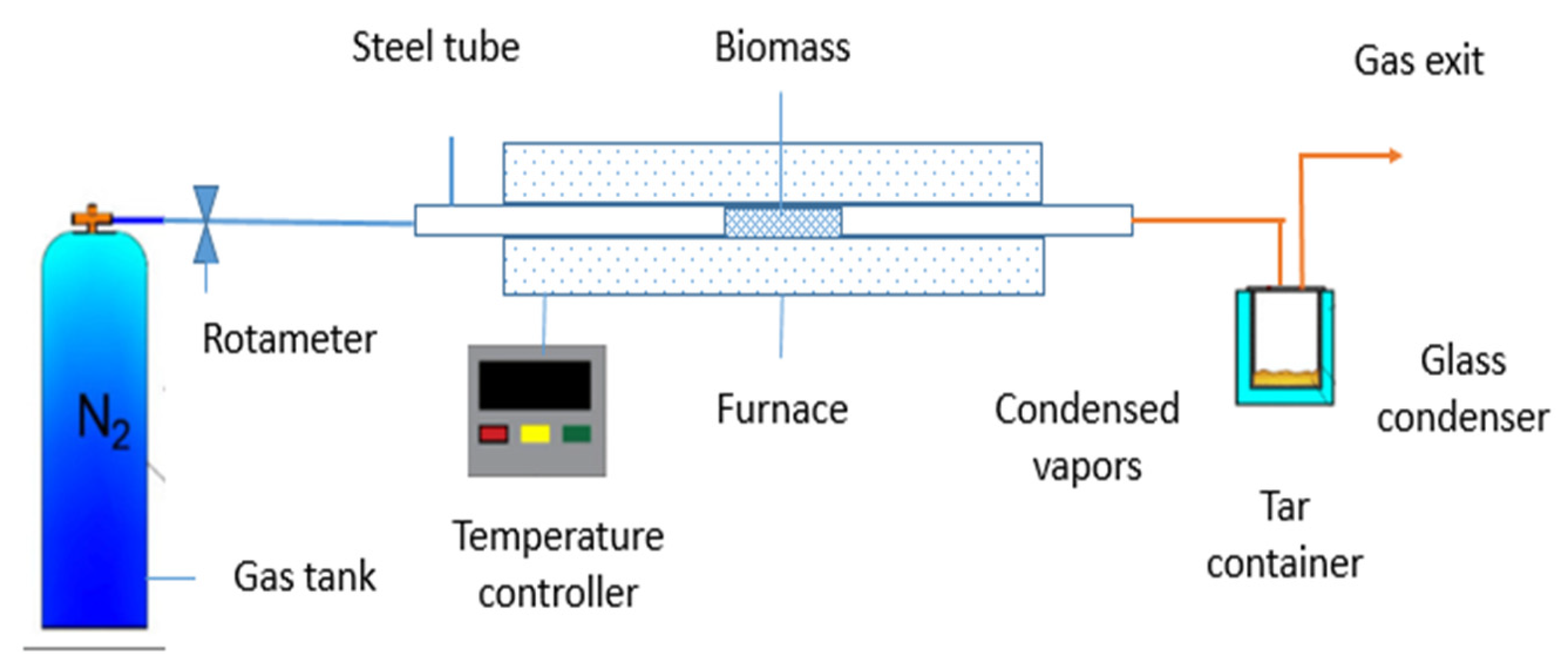
The pyrolysis is carried out in a tube furnace as shown in Figure 1 and Figure 2. In this research, we use N2 as inert gasses during pyrolysis experiments. A horizontal furnace (Lenton thermal) and a vertical tube furnace (Nabertherm GmbH) were used. The tube of these tow two furnaces was charged with okara powder waste in an N2 flow. In our pyrolysis experiment, dried biomass or okara is supplied, and the high temperatures of 600 oC are used to carbonize a significant amount of feedstock, the heating rate is maintained at 3oC/min, and residence time is maintained for 1 hour. Schematic of the vertical and horizontal batch pyrolysis system setups is shown in Figure 1 and Figure 2 below:

2.1.2. Preparation of Activated Carbon via Hydrothermal Carbonization Method

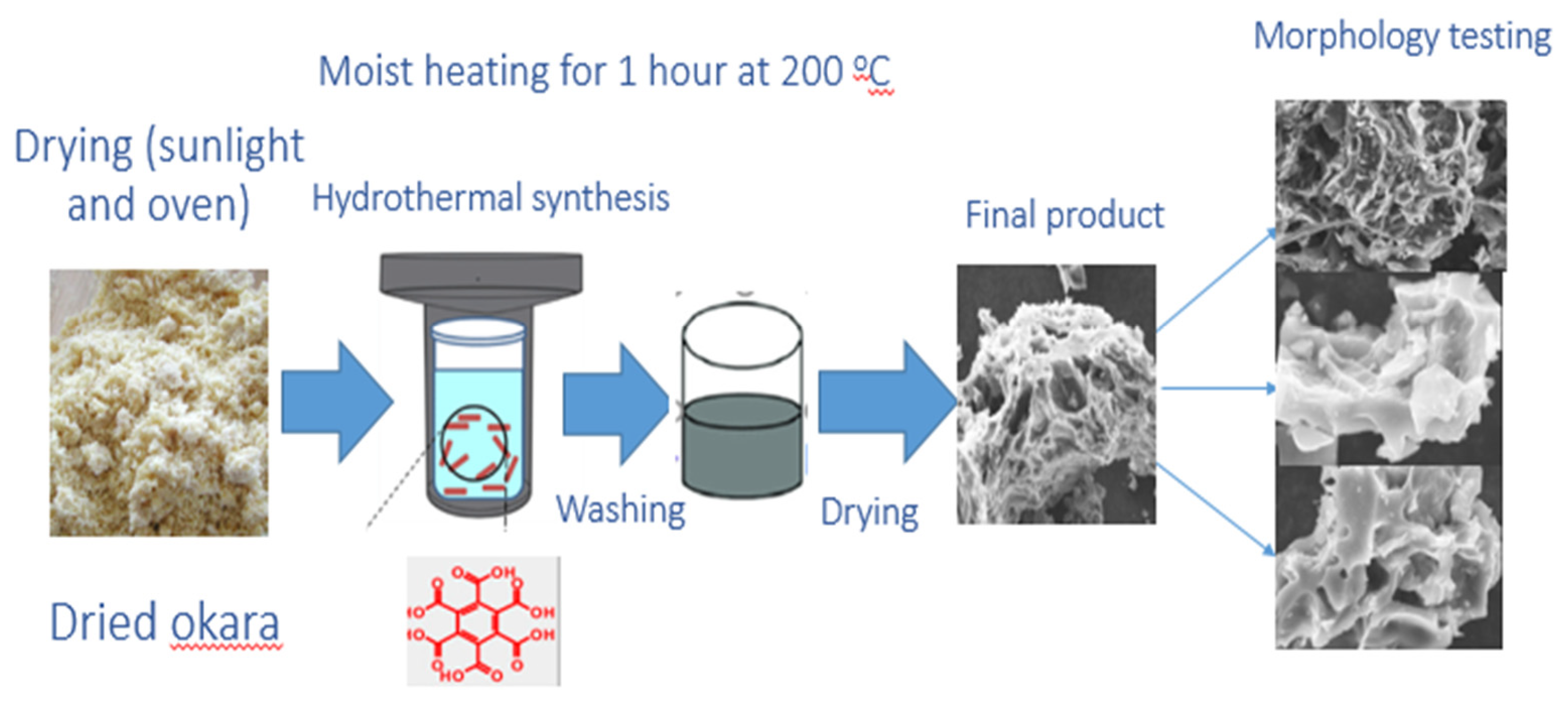
In this study, HTC is performed at 200 °C, during which biomass is submerged in water and heated in a closed system (a steel autoclave) under pressure (2–6 MPa) for 240 minutes. An amount of 12.8 g okara powder waste and 40 ml of water (equivalent to 2/3 volume of a medium-sized stainless steel autoclave) was placed in a stainless steel autoclave, heated up to 200 °C, and kept at this temperature for 4 hours; then leave the stainless steel autoclave to cool down overnight. The next day the sample is filtered with filter paper, and washed with distilled water to about neutral pH. HTC method to prepare hydrochar is illustrated in Figure 3.

2.1.3. Activate Biochar/Hydrochar

For some samples, (i.e sample OPW6), the activated carbon was prepared from the bichar/hydrochar of dried okara through physiochemical activation processes. The biochar, produced at a 600 ◦C pyrolysis temperature, or hydrochar produced at 200 oC hydrothermal treatment was used for further treatment, to produce a high porosity product with less tars impurity [34]. The biochar/hydrochar was mixed with KOH and water with a mass ratio of biochar: KOH: water being 1:4:5. This sample was then kept in a beaker at room temperature for 48 h. After this KOH impregnation step, the mixture was oven-dried overnight at 100 ◦C. Then, the dried mixture was again pyrolyzed at 600 ◦C temperature for 1 h with a heating rate of 25 ◦C/min under nitrogen gas (99.99% purity) flow of 1.5 L/min. After pyrolysis, the activated carbon was washed with hot and aqueous HCl to remove excess KOH and impurities until the pH value of the drained liquid was neutral. Finally, the AC was dried in the oven and stored in a zipper bag. The size of the activated carbon was less than 0.25 mm due to the biomass precursor’s size. The list of the synthesized samples is presented in Table 1.

2.2. Characterization of the Materials

The porous carbon materials were examined by scanning electron microscopy (SEM) by a Jeol, JCM-7000 microscope. The EDS analyses were performed with a 15 kV accelerating voltage. Brunauer-Emmett-Teller (BET) surface area was measured using a Micromeristics, ASAP 2060 device. TGA and DSC were performed by a NETZSCH (STA 449 F5 Jupiter) equipment. FTIR measurements were performed by a Thermal Scientific – NICONET iS5050 FTIR. All absorbance spectra were obtained in the 4000–400 cm-1 range by 100 scans at 1.0 cm-1 resolution.

2.3. Calculation of the biomass conversion

Two factors that measure the efficiency of AC production and mass loss are burn-off and carbon yield. Burn-off measures the mass lost after the activation and is calculated from Equation (1.1) [35].
b u r n   o f f w t . % = w o w A C w o · 100 %
where wo is the initial weight and wAC is the dry weight of the resulting activated carbon after activation (the mass of the final activated carbon).
The carbon yield of each stage is determined using Equation (1.2) [36,37]:
C a r b o n y i e l d w t . % = w C w f · 100 % = m a s s   o f   c a r b o n   m a t e r i a l s   a f t e r   p y r o l y s i s m a s s   o f   o k a r a   p o w d e r   w a s t e   f e e d s t o c k * 100 %
where wC is the weight of carbon (g), and wf is the weight of feed (g).

3. Results and Discussions

3.1. Characterizations of the Biomass Materials

3.1.1. EDX Analysis of Various Biomass

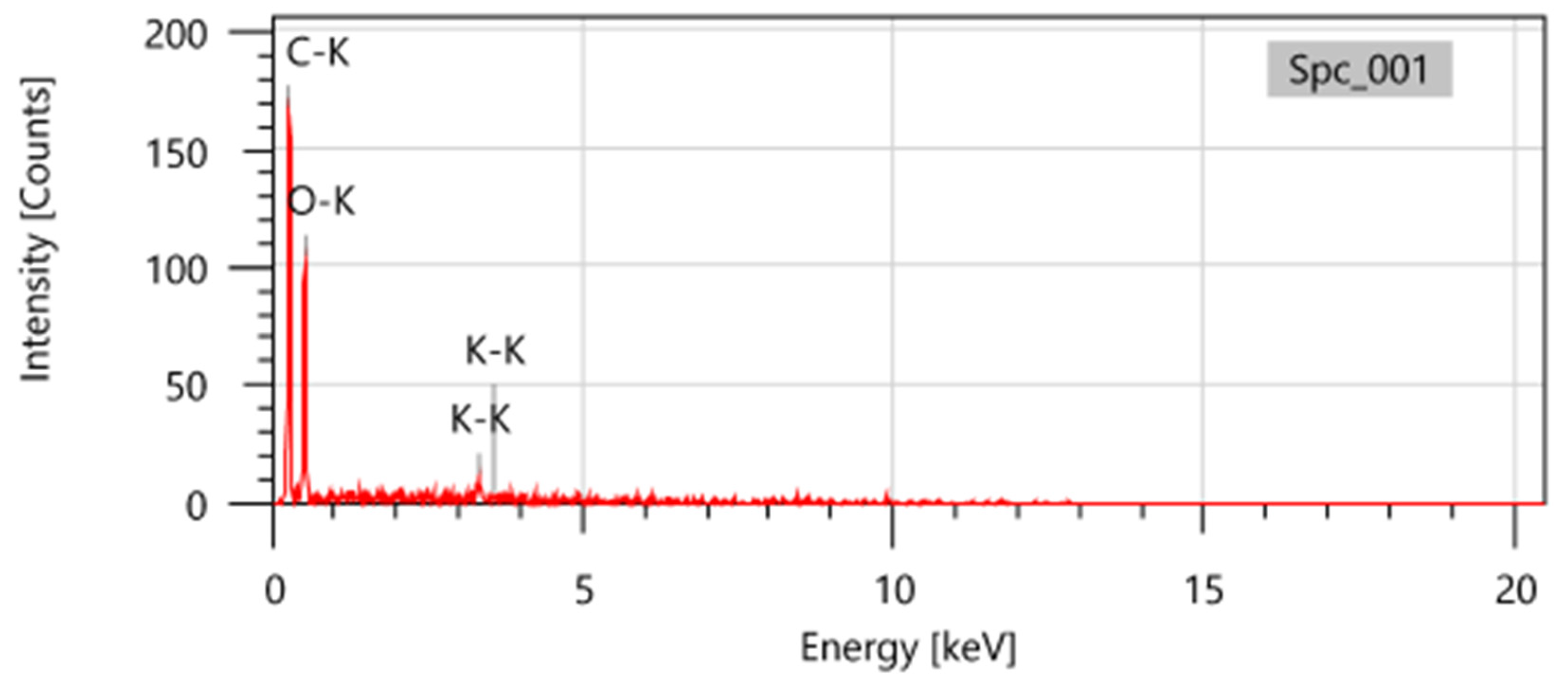
EDX analysis was used to examine the elements of the biomass. The element composition of different biomass is presented in Table 2. The table shows that the biomass consists of 18.91% to 57.35 % of carbon weight, 42% to 55 % of oxygen weight, and 1.74 to 5.77% of K weight. For okara powder waste, the okara consists of 45.73% of carbon mass, 52.53% of oxygen weight, and 1.74% of K mass. It can be seen that okara powder possesses an average carbon mass compared to other biomass but it is one of the two biomass containing K, which may help for the activation process for improving surface area and for the adsorption of CO2. Moreover, the source of okara waste is abundant with low economic value (it is only used for planting and fodder) so it may be a good selection for a pyrolysis process.
The EDX image of the okara waste is shown in Figure 4. The element concentrations suggest the presence of a high amount of different oxygenated groups on the carbon surfaces, and the presence of K, whose contents is 1.74%. According to the literature, Cl, Ca, Na, Cu, Mg, K, Ni, Si, and P contents in the different biomass are between 0.09 and 1.21 % [31,32].

3.1.2. SEM Images of Different Biomass

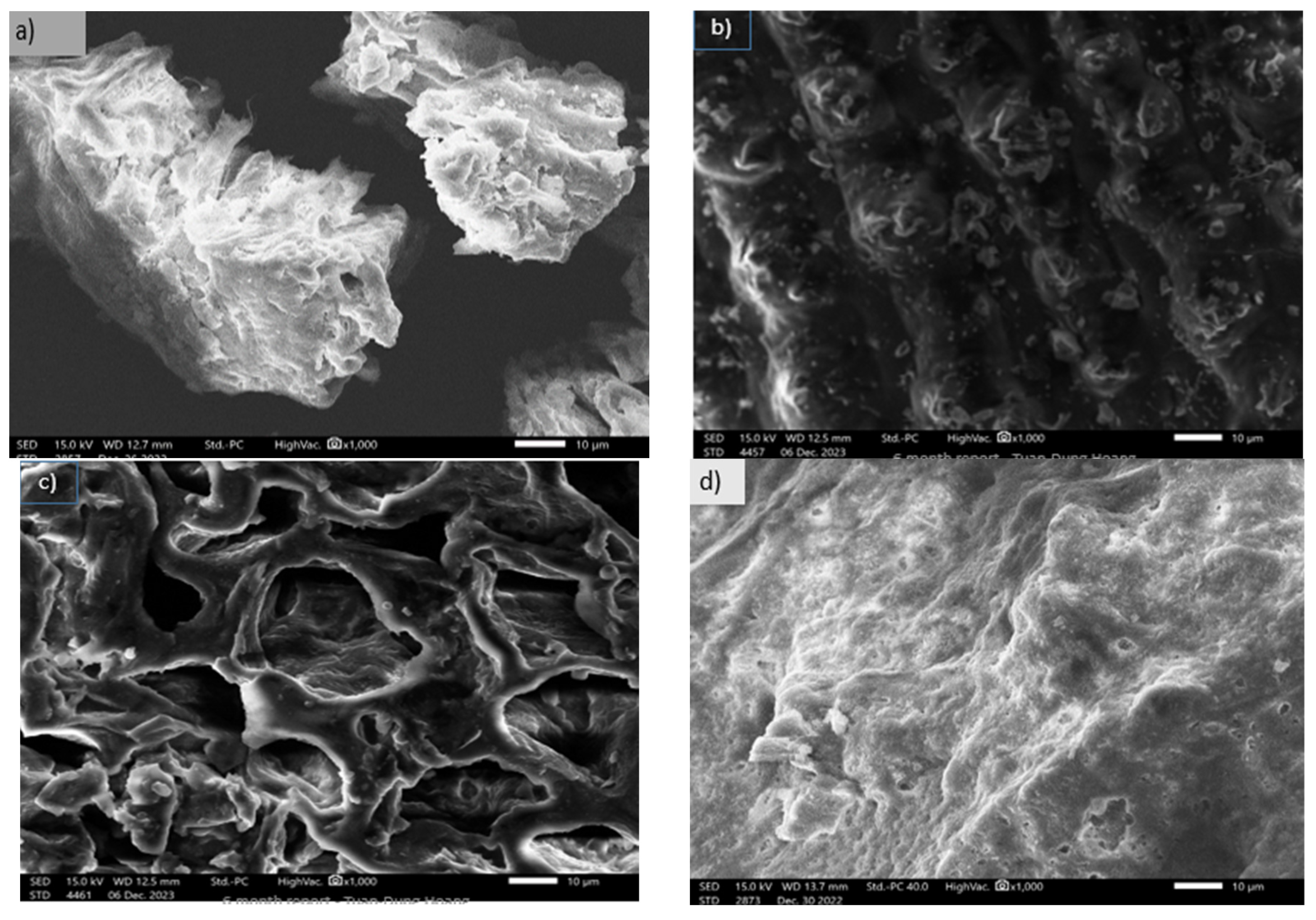
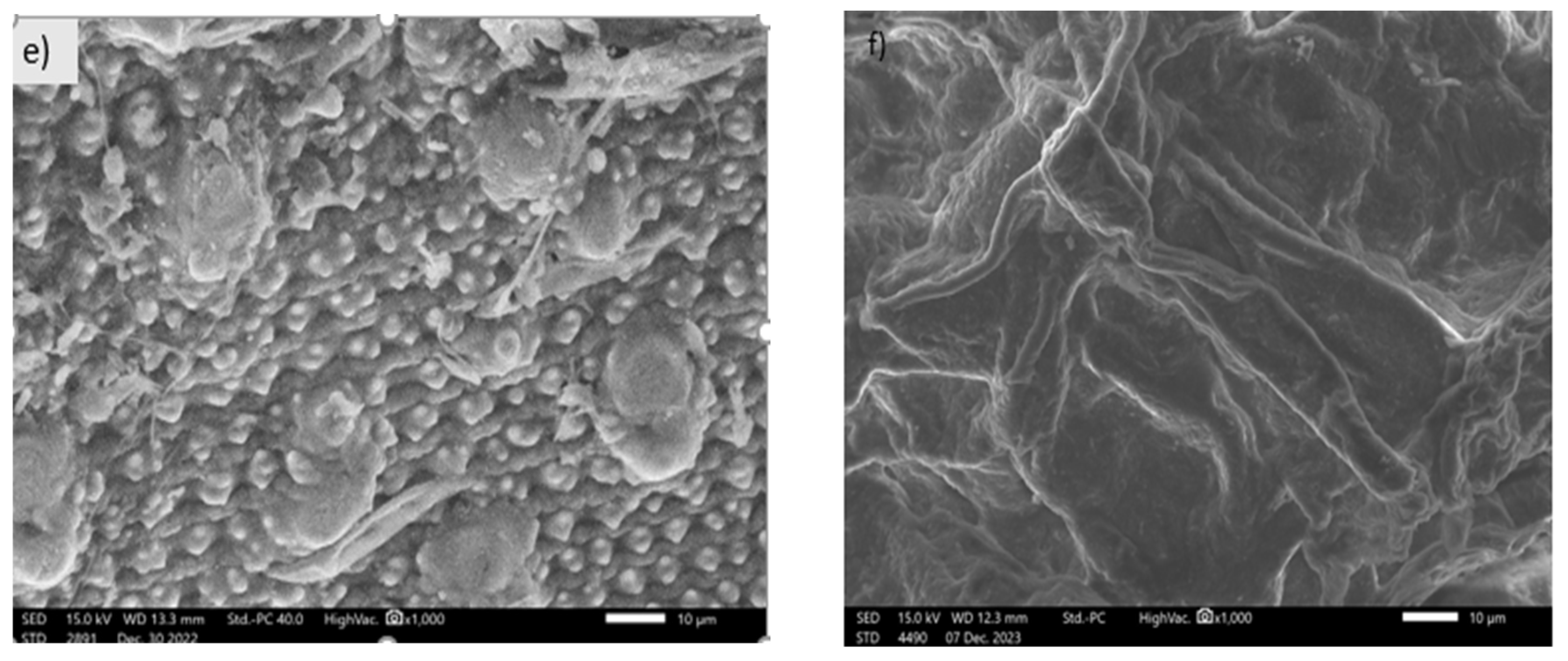
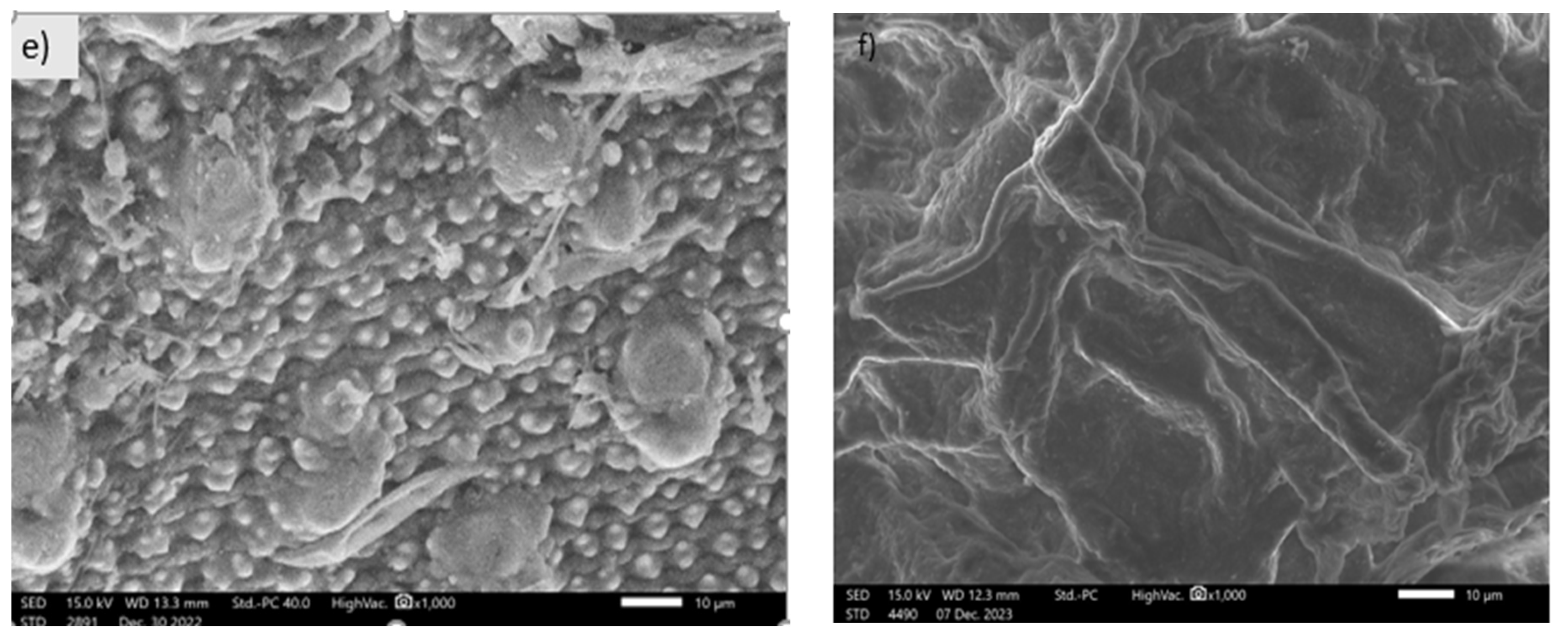
SEM was employed to investigate the surface morphology and porous structure of the precursor materials. As shown in Figure 5 SEM images, the surface morphology properties of the biomass precursors were remarkably influenced by the different types of biomass feedstock. The surface morphology of the samples b), c), and e) was intricately changed and the pores were gradually opened with deep holes while the surface morphology of the samples f), d) were relatively flat and simple. Large pores and cavities are also evident in the case of coffee waste.

3.1.3. SEM Images of Activated Carbon Synthesized from Okara Powder Waste

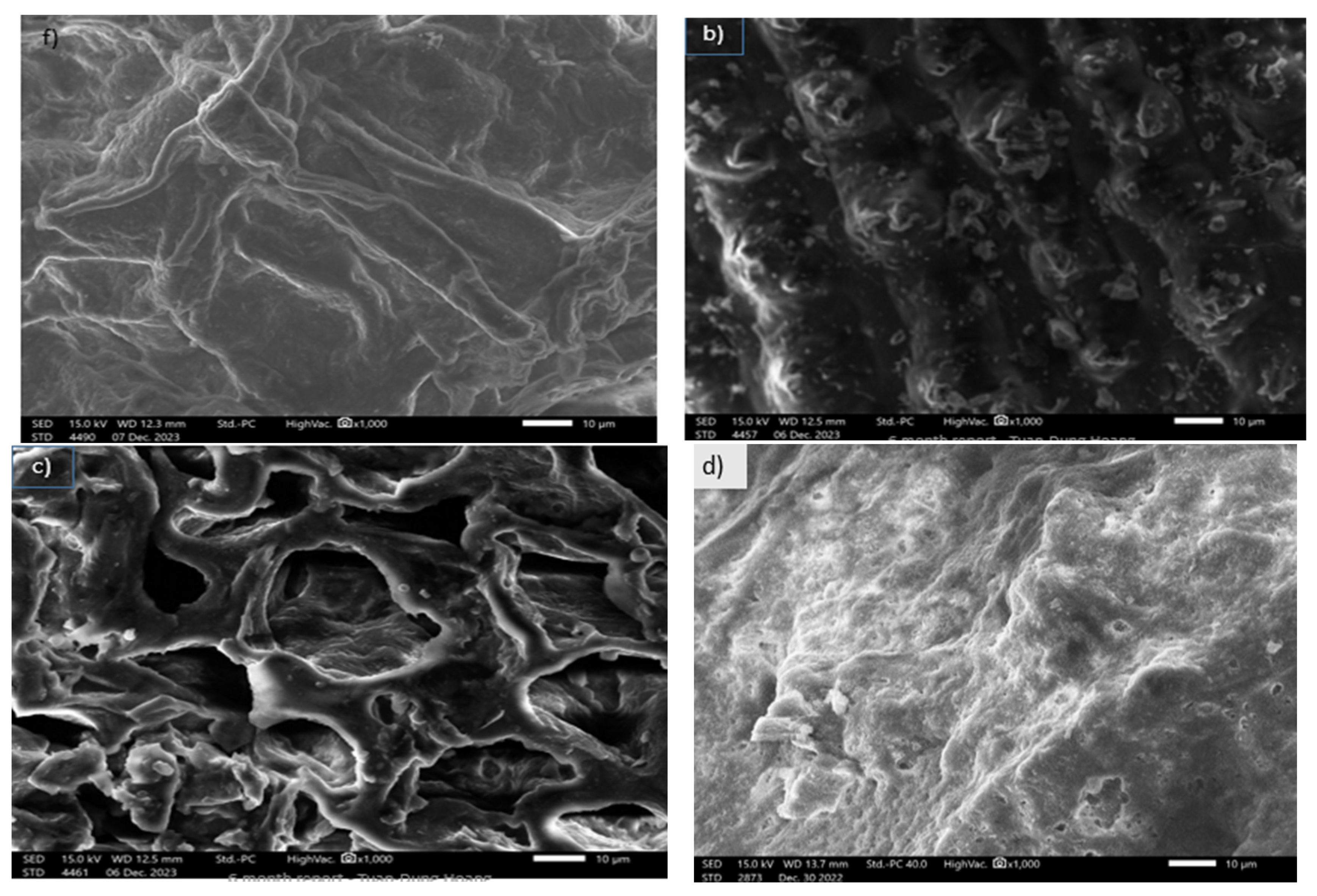
The SEM image of the activated carbon obtained after the pyrolysis process is illustrated in Figure 6.
The images exhibited clear pores and specific shapes on the surface of the biochar. This is possible due to the development of internal pores after tars were removed inside the biochar by the activating agents through physicochemical activation. Higher porosity is very important for the latter CO2 uptake processes of our study and these images demonstrate a porous surface area of biochar. It could also be observed that this biochar presented as a conglomeration of spheres. The surface topology differed strongly between raw okara powder waste and biochar, which is in good agreement with the previous publication [33]. The structure of the biochar materials was shown to be porous and this creates a perfect surface environment for the CO2 diffusion and adsorption inside the structure of the materials in the latter phase of the research.

3.1.4. FTIR Analysis

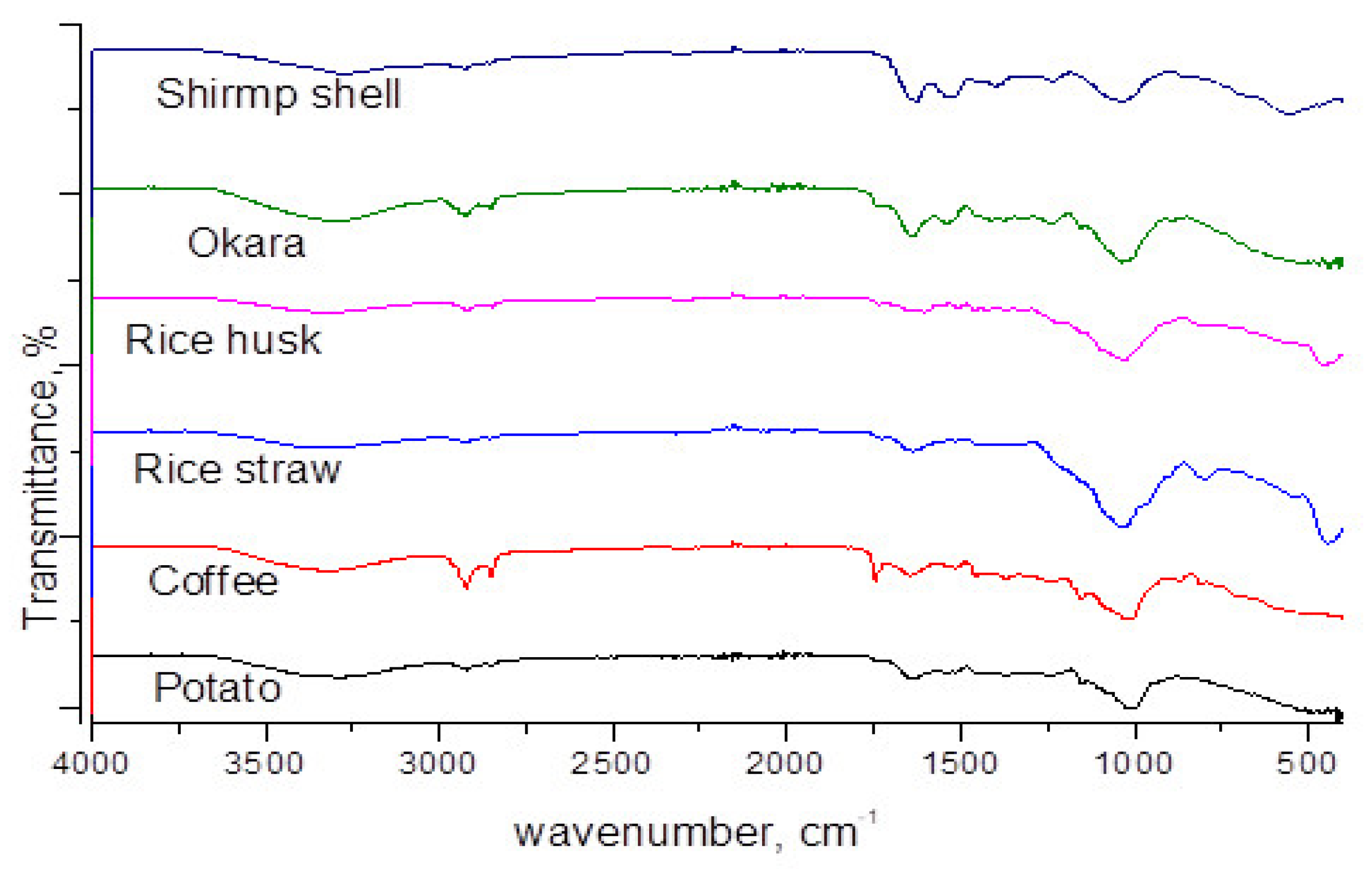
The FTIR spectroscopy technique was used to identify the functional groups on the surface of the biomass, as shown in Figure 7.
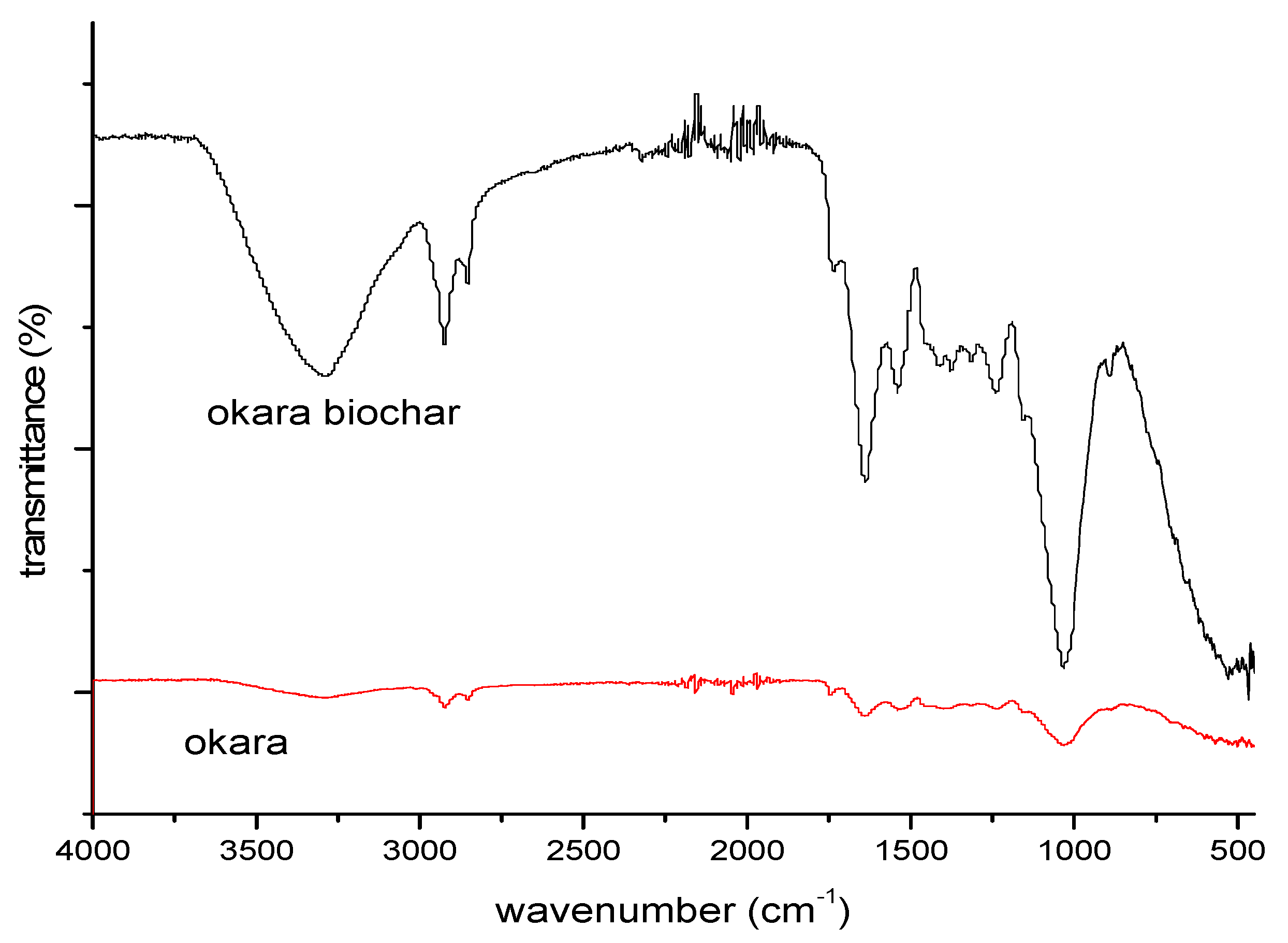
The absorption bands at 1800–1600 cm-1 (centered at 1567 cm–1) were due to the stretching vibration of νC = O and νC = C [38]. The peaks at 1000 cm-1 (centered at 1000 cm–1) were recognized as the νC–O stretching vibrations, which resulted from the hydroxyl, ester, and ether functional groups on the surface of the biomass [38]. Figure 7 displays different biomass contains some different vibrations, confirming that the chemical structures of different biomass are featured. Figure 8 illustrates the Fourier Transform-Infrared spectra of okara biomass and okara biochar.

3.1.5. TG-DSC Analysis

The thermogravimetry (TG) method is used to measure the mass change of an okara powder under the pyrolysis condition. A sample weighing 3–4 mg was placed into a crucible placed on a sling balance, and the parameters were set as follows: initial temperature: 25 °C; heating rate: 10 °C/min; termination temperature: 600 °C; nitrogen flow: 50 mL/min. The mass changes were recorded continuously to obtain their thermogravimetric curves. DSC measurement was performed at the same time.
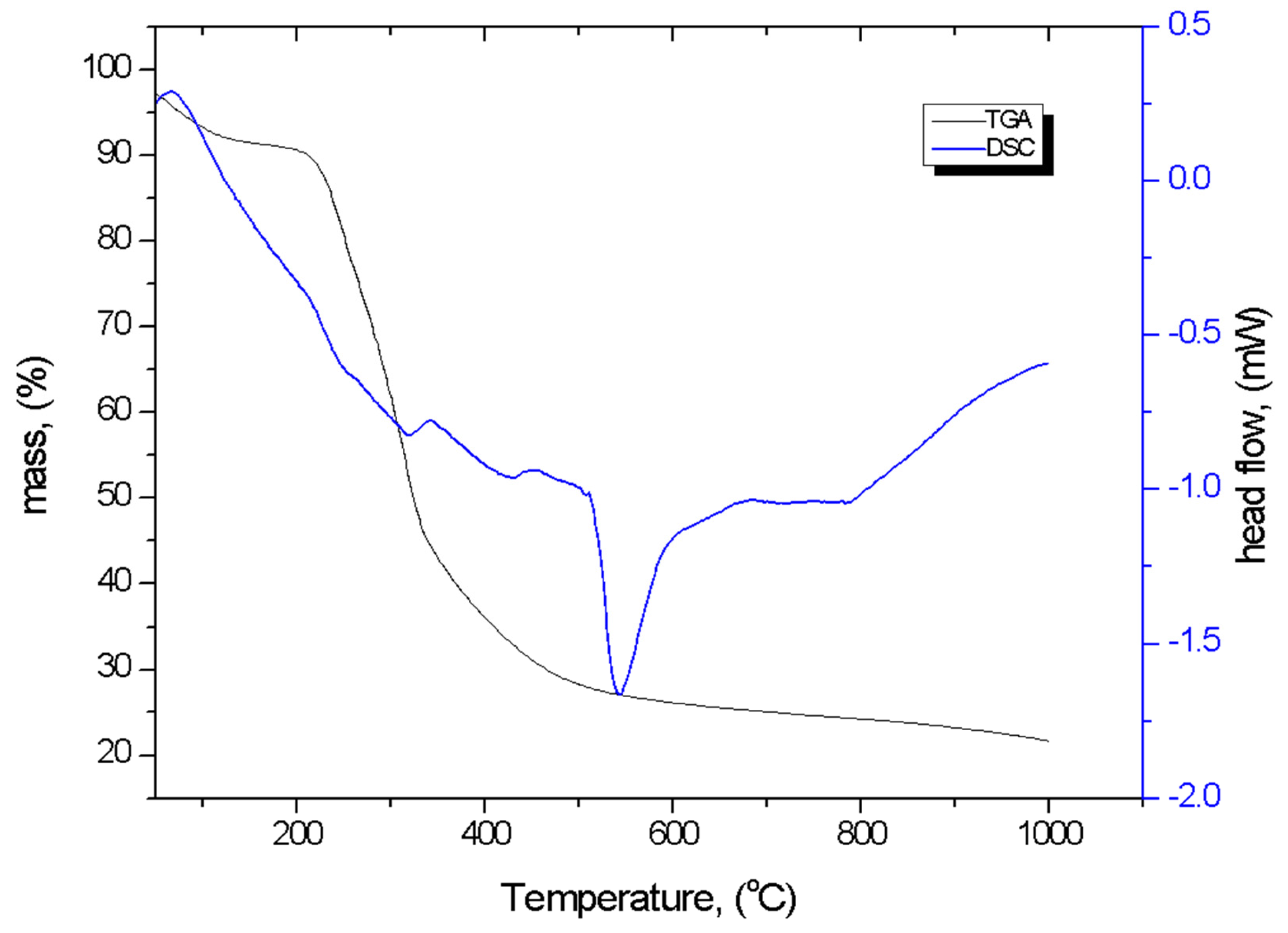
The TGA-DSC profile of okara powder waste is presented in Figure 9. It can be seen that the sample mass decreases slightly during the first minutes of measurement at temperatures lower than 200 °C (the first stage), decreases significantly from the temperature of 200 °C up to 400 °C (the second stage), and again slightly decreases from the temperature of 400 °C up to 1000 °C (the 3rd stage). The 1st stage is the drying stage, where the evaporation of free water and crystal water inside the fiber of okara happens. The 2nd stage or carbonization stage happens due to the thermal decomposition or degradation of cellulose and hemicellulose of the okara. The 3rd stage or combustion stage happens when the temperature exceeds 400 °C, and the thermogravimetric curve trend becomes stable due to the gradual decomposition of the residual sample into carbon and ash [6]. Thus, at a pyrolysis temperature of 600oC, the decomposition of the biomass is expected to be completed. The total mass lost if about 75%.
DSC analysis was used as a complementary and supplementary technique to TGA to determine the transition temperatures of the samples as a function of heat flow, as well as establish phase changes caused by thermal exposure as a result of blending [39]. The DSC plot in Figure 9 also indicated that okara sample displayed some endothermic peaks. The first peak appears at 319.8 °C, -0.8254 mW/mg, and a deep peak occurs at 542.8 °C, -1.665 mW/mg. The formation of the endothermic peaks and the modification temperature for the okara sample were evidence of increased burning and heat flow rates that were facilitated by auto-oxidation reactions because of the presence of oxygen-containing functional groups in the structure of the okara sample. The head flow values also indicate that before 542 oC, the heat flow reduces significantly, while from this transition temperature at 542 oC, upward), the head flow increases gradually [39].
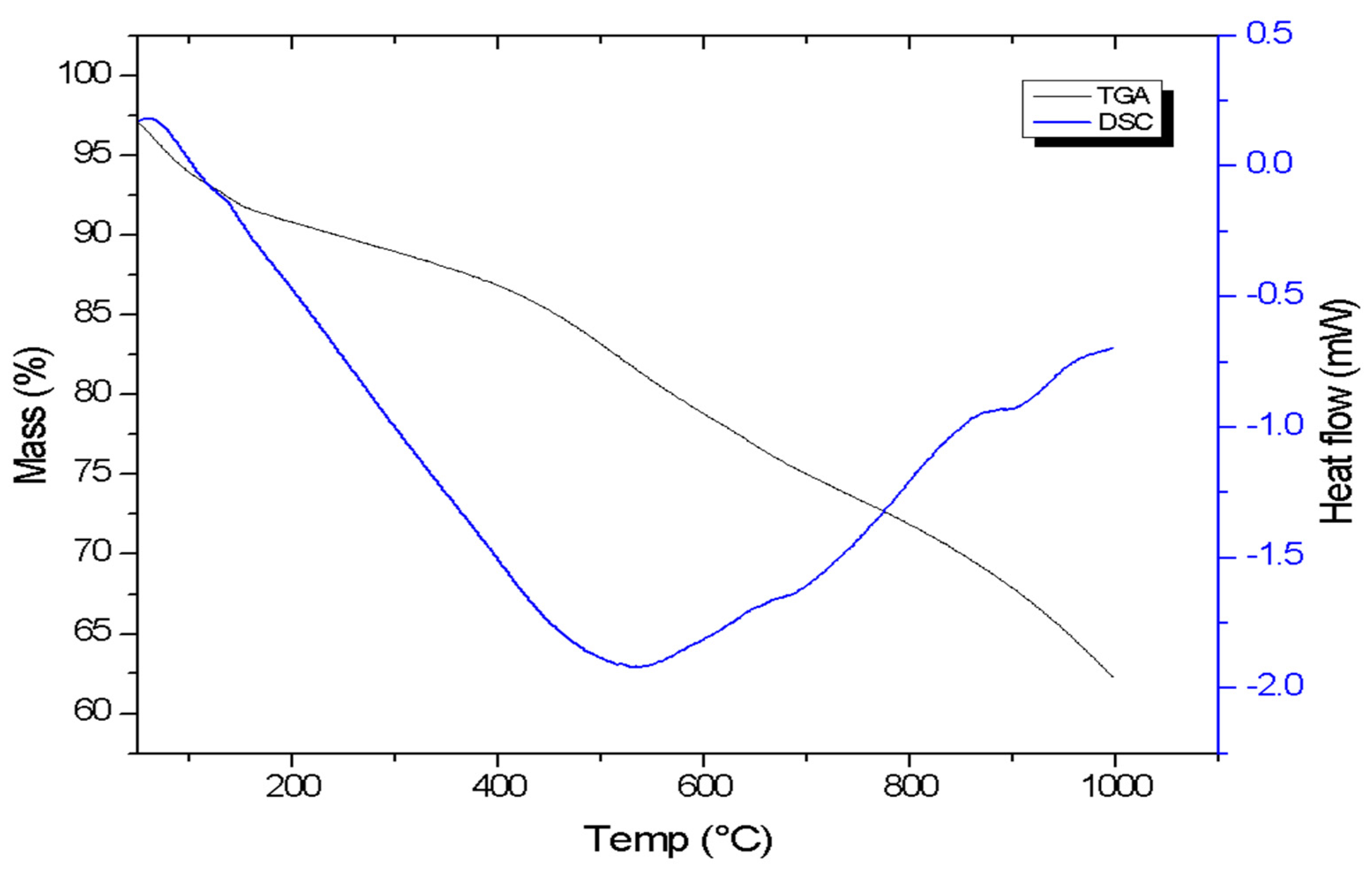
The TGA-DSC profile of hydrochar obtained from okara powder waste by the HTC method (OPW4) is presented in Figure 8. Results suggest that the DSC curves of dried okara biomass and its hydrochar samples, as shown, are significantly different.
Thermogravimetric experiments on okara powder waste showed that okara powder waste is a quite reactive material compared to its hydrochar obtained by HTC as the total mass lost of the decomposition of hydrochar is only 32% while it is 75% for okara waste powder. It means that during the HTC process, about 43% mass has been lost and the decomposition of the materials during the calcination at high temperatures in N2 flow is less heavy.

3.2. Pyrolysis Products and Their Properties

Bio-oil, bio-char, and pyro-gas are essential byproducts of biomass pyrolysis [16,40]. The key constituent of pyrolysis substance is bio-oil, also known as pyrolysis oil, pyrolysis liquid, pyrolysis tar, bio-crude, wood liquid, wood oil, or wood distillate, among other names. This is often a dark brown, free-flowing liquid with a strong smoky, pungent odor. This is an intensely polar substance that is largely immiscible with nonpolar petroleum-derived fuels. The solid residue left over from the pyrolysis of carbonaceous biomass is known as biochar. The properties of biochar are primarily determined by the process and biomass used. Pyro-gas is primarily composed of CO, CH4, CO2, and H2 and has a heating value of 6.4–9.8 MJ/kg. It is used internally as process heat for pyrolysis.
  • Biochar and hydrochar yield and burn-off
The carbon yield is commonly used to measure the effectiveness of a process conversion
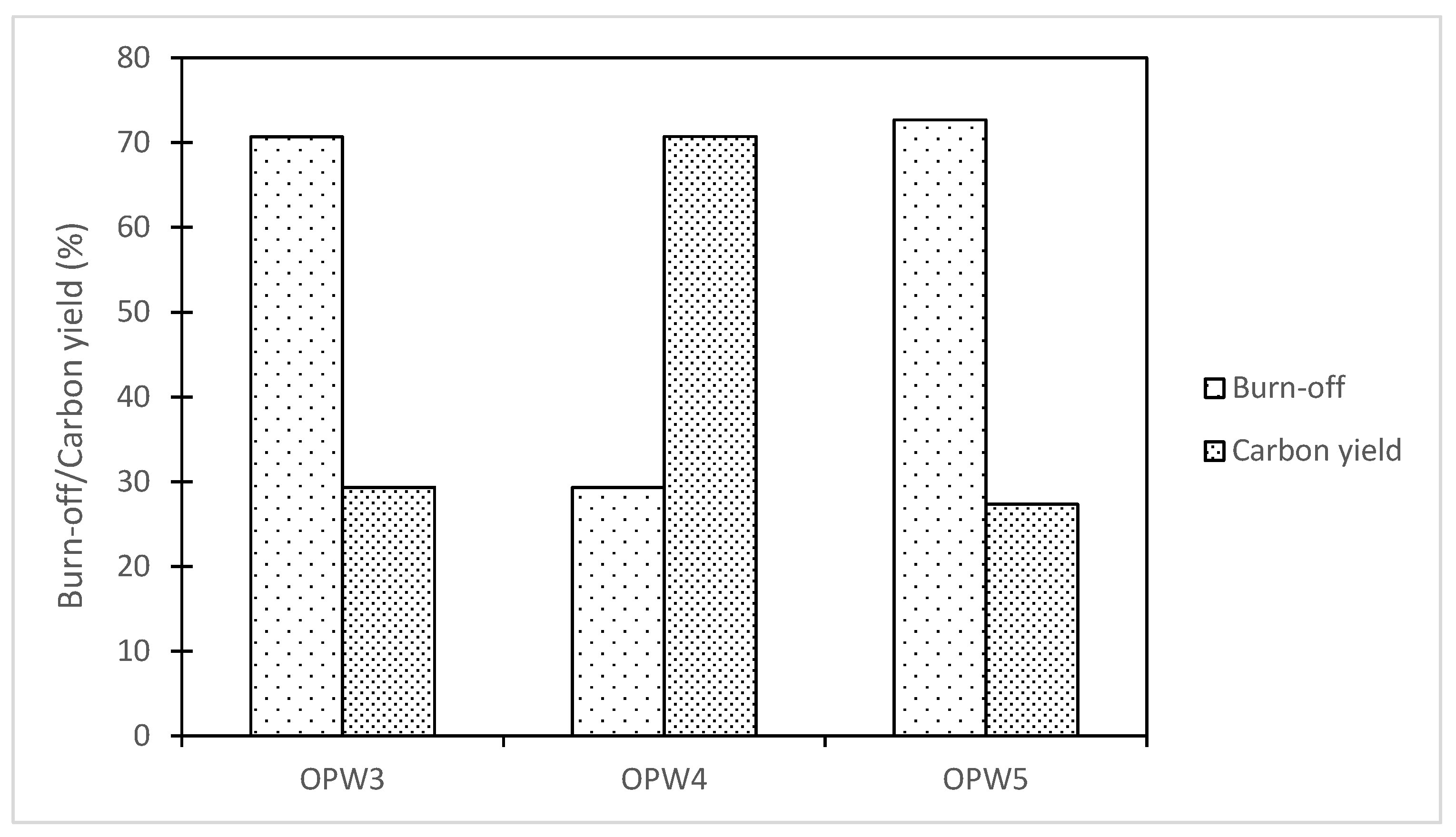
Carbon yield and burn-off of Several pyrolysis experiments are presented in Figure 11.
With the samples conducted, the burn-off value is ranging from 0.29 to 0.71 %. For the OPW3 sample, the result is in good agreement with the TGA result. For the hydrothermal process without using zeolite (OPW4), the burn-off is much less, indicating that the carbonization is not yet complete. However, with the use of a zeolite catalyst, the burn-off increased significantly to the same value as the carbonization at 600 oC. Thus, the use of zeolite enhances the carbonization to help the process to occur at lower temperatures.
  • Surface areas (S/BET) and pores:
Several samples have been analyzed to verify their surface areas. Table 3 is a summary of our samples tested and their S(BET) in comparison with the literature results.
The results show that the pyrolysis temperature influences the surface area of biochar, when the temperature exceeds 600 oC, the surface area is very small (about 1m2/g). A surface area of 20.73 m2/g is obtained for the sample carbonized at 600 oC, however, it is still small to be used as an adsorbent.
The surface area of hydrochar is a little higher than that of biochar obtained at high temperatures (above 650 oC), especially when zeolite and KOH melamine is used to catalyze the decomposition but the surface area is only 14 m2/g.
The addition of KOH into biochar has possibly created small holes deep into the activated carbon surface. Thus, the SBET result of the porous ACs after activation has enlarged up to 104. m2 g -1 (OPW7) compared to the pre-activated carbon process which is only 14 and 20 m2 g -1. When the ratio of KOH increases, the surface area increases (OPW10) since KOH reacted with C to form CO2 [44] and results more pores for the AC so with a suitable amount of KOH, the surface area can reach almost 600 m2/g:
2KOH → K2O + H2O
C + H2O → H2 + CO
CO + H2O → H2 + CO2
K2O + CO2 → K2CO3
Overal reaction: 4KOH + C → K2CO3 + K2O + 2H2
KOH was also mixed with okara biochar without using water and stabilized for a few days (OPW8 and OPW9). In that case, the surface area of Acs was also improved but only reached to around 200 m2/g, thefore the stabilize of the biochar and KOH for some days is important for KOH to interact homogenously with the whole carbon sample to make it convenient for the following reaction during the next calcination at 600 oC.
For comparison, rice husk and potato peel were also simply carbonized at 600 oC (without activating with KOH). These samples showed much higher surface areas compared to the okara sample at the same carbonization process. It revealed that okara waste is possible to produce AC with a suitable surface area to serve as an adsorbent but may not be an excellent candidate to produce extremely high surface area adsorbents.

4. Conclusions and Outlooks

In the context of global warming, sustainable development, and NetZero targets [45], agricultural residues are promising sources of potential materials for various applications, ranging from energy storage, aqueous environmental treatment, biofuels, and CO2 capture [2,10,17,46]. This study used biomass sources to obtain useful products, namely porous carbon materials - a CO2 adsorbent by using the slow pyrolysis and hydrothermal processes. More importantly, okara powder waste was chosen to be focused on because they are cheap, abundant in Asian countries, and easy to harvest.
The adsorbent synthesized from the pyrolysis and hydrothermal processes in this study provide porous characteristics. To investigate the adsorption of the activated carbon the thermal chemical activation was performed. While with no activating agent, the surface areas of the adsorbent were small, but when activated agents were added in a combined pyrolysis and chemical activation method, the SBET of the adsorbent significantly increased. Carbon yields range from 30% to 70 % for slow pyrolysis processes. Pyro-gas is primarily composed of CO, CH4, CO2, and H2. Regarding the pyrolysis and HTC, we conclude that the HTC is not sufficient, solid acid catalysts (zeolite) could accelerate the carbonization in HTC (evidenced in the TGA analysis). The pyrolysis without an activating agent (or activator) shows a low surface area. And activator addition (wet vs dry thermal chemical process increases the surface area). Wet activator addition (KOH amount) increases the BET surface area.
While the current results on activated carbons synthesized from okara and other biomasses have been done, future research should continue on CO2 uptake in these materials. Okara waste, which has never been studied previously, is possible to produce AC with a suitable surface area (about 600 m2/g) to serve as an adsorbent but may not be an excellent candidate to produce extremely high surface area adsorbents. Further studies on CO2 capture using the activated carbon materials developed are needed.

Author Contributions

Conceptualization, T.D. Hoang, L.M. Thang, Liu Y.; methodology, T.D. Hoang, L.M. Thang, Liu Y.; validation, T.D. Hoang, L.M. Thang, Liu Y; Formal analysis, T.D. Hoang; investigation, T.D. Hoang L.M. Thang, Liu Y.; Resources, T.D. Hoang, L.M. Thang, Liu Y.; data curation, T.D. Hoang, L.M. Thang, Liu Y.; writing—original draft preparation, T.D. Hoang.; writing—review and editing, T.D. Hoang, L.M. Thang, Liu Y.; visualization, T.D. Hoang.; supervision, L.M. Thang, Liu Y.; project administration, L.M. Thang, Liu Y.; funding acquisition, T.D. Hoang, L.M. Thang, Liu Y. All authors have read and agreed to the published version of the manuscript.

Funding

This research was funded by the German Academic Exchange Service (DAAD, No. 57315854. The APC was funded by MDPI.

Institutional Review Board Statement

Not applicable.

Informed Consent Statement

Not applicable.

Data Availability Statement

The data presented in this study are available in this article. Data supporting reported results can be provided upon request.

Acknowledgments

Sincere thanks go to the RoHan Project funded by the German Academic Exchange Service (DAAD, No. 57315854) and to the Federal Ministry for Economic Cooperation and Development (BMZ) of Germany inside the framework of the “SDG Bilateral Graduate School program” for funding T.D.H this research at GeViCat, HUST. Tuan-Dung Hoang also would like to thank Anh Phan, at the School of Engineering, university of Newcastle, for her comments on the manuscript.

Conflicts of Interest

The authors declare no conflict of interest concerning the research, authorship, and/or publication of this article. The funders had no role in the design of the study; in the collection, analyses, or interpretation of data; in the writing of the manuscript; or in the decision to publish the results.

References

  1. Friedlingstein, P., et al., Update on CO2 emissions. 2010. 3(12): p. 811-812. [CrossRef]
  2. Hoang, T.-D., et al., Carbon-Based Synthesized Materials for CO2 Adsorption and Conversion: Its Potential for Carbon Recycling. 2023. 8(4): p. 53. [CrossRef]
  3. Yoro, K.O. and M.O. Daramola, CO2 emission sources, greenhouse gases, and the global warming effect, in Advances in carbon capture. 2020, Elsevier. p. 3-28.
  4. Olivier, J.G., K. Schure, and J.J.P.N.E.A.A. Peters, Trends in global CO2 and total greenhouse gas emissions. 2017. 5: p. 1-11.
  5. Gao, J., S.C.S. Shiong, and Y.J.C.E.J. Liu, Reduction of CO2 to chemicals and Fuels: Thermocatalysis versus electrocatalysis. 2023: p. 145033. [CrossRef]
  6. Liu, J., et al., Biomass pyrolysis mechanism for carbon-based high-value products. Proceedings of the Combustion Institute, 2023. 39(3): p. 3157-3181. [CrossRef]
  7. Dziejarski, B., et al., CO2 capture materials: a review of current trends and future challenges. 2023: p. 100483. [CrossRef]
  8. Furuvik, N.C., et al., Experimental study and SEM-EDS analysis of agglomerates from gasification of biomass in fluidized beds. 2022. 252: p. 124034. [CrossRef]
  9. Hoang, T.-D. and N.J.F. Nghiem, Recent developments and current status of commercial production of fuel ethanol. 2021. 7(4): p. 314. [CrossRef]
  10. Sezali, N.A.A., et al., Bio-based nanomaterials for energy application: A review. 2024. [CrossRef]
  11. Fan, H., et al., Structural Characteristics of Insoluble Dietary Fiber from Okara with Different Particle Sizes and Their Prebiotic Effects in Rats Fed High-Fat Diet. 2022. 11(9): p. 1298. [CrossRef]
  12. Liu, K., Food use of whole soybeans, in Soybeans. 2008, Elsevier. p. 441-481.
  13. Xiao, C., Functional soy products, in Functional foods. 2011, Elsevier. p. 534-556.
  14. Rahman, M.M., et al., A review of okara (soybean curd residue) utilization as animal feed: Nutritive value and animal performance aspects. 2021. 92(1): p. e13594. [CrossRef]
  15. Li, B., M. Qiao, and F.J.F.R.I. Lu, Composition, nutrition, and utilization of okara (soybean residue). 2012. 28(3): p. 231-252. [CrossRef]
  16. Abi Bianasari, A., et al., Influence of combined catalysts on the catalytic pyrolysis process of biomass: A systematic literature review. 2024. 309: p. 118437.
  17. Tran, T.-K., et al., Applications of engineered biochar in remediation of heavy metal (loid) s pollution from wastewater: Current perspectives toward sustainable development goals. 2024: p. 171859. [CrossRef]
  18. MINH, T.Q., et al., KHẢO SÁT KHẢ NĂNG HẤP PHỤ CIPROFLOXACIN TRONG NƯỚC BẰNG THAN SINH HỌC CÓ NGUỒN GỐC TỪ RONG BIỂN ĐƯỢC ĐIỀU CHẾ THÔNG QUA QUÁ TRÌNH CÁC-BON HÓA THỦY NHIỆT VÀ HOẠT HÓA ZnCl.
  19. Amalina, F., et al., Biochar production techniques utilizing biomass waste-derived materials and environmental applications–A review. 2022. 7: p. 100134. [CrossRef]
  20. Toscano Miranda, N., et al., Sugarcane bagasse pyrolysis: A review of operating conditions and products properties. Renewable and Sustainable Energy Reviews, 2021. 149: p. 111394. [CrossRef]
  21. Kan, T., V. Strezov, and T.J. Evans, Lignocellulosic biomass pyrolysis: A review of product properties and effects of pyrolysis parameters. Renewable and Sustainable Energy Reviews, 2016. 57: p. 1126-1140. [CrossRef]
  22. Vuppaladadiyam, A.K., et al., A critical review on biomass pyrolysis: Reaction mechanisms, process modeling and potential challenges. Journal of the Energy Institute, 2023. 108: p. 101236. [CrossRef]
  23. Lee, S.Y., et al., Waste to bioenergy: a review on the recent conversion technologies. BMC Energy, 2019. 1(1): p. 4. [CrossRef]
  24. Ghodake, G.S., et al., Review on biomass feedstocks, pyrolysis mechanism and physicochemical properties of biochar: State-of-the-art framework to speed up vision of circular bioeconomy. Journal of Cleaner Production, 2021. 297: p. 126645. [CrossRef]
  25. Sharma, R., et al., A Comprehensive Review on Hydrothermal Carbonization of Biomass and its Applications. Chemistry Africa, 2020. 3(1): p. 1-19. [CrossRef]
  26. Bach, Q.-V. and Ø. Skreiberg, Upgrading biomass fuels via wet torrefaction: A review and comparison with dry torrefaction. Renewable and Sustainable Energy Reviews, 2016. 54: p. 665-677. [CrossRef]
  27. Yoganandham, S.T., G. Sathyamoorthy, and R.R. Renuka, Emerging extraction techniques: hydrothermal processing, in Sustainable seaweed technologies. 2020, Elsevier. p. 191-205.
  28. Marzbali, M.H., et al., Wet organic waste treatment via hydrothermal processing: A critical review. Chemosphere, 2021. 279: p. 130557. [CrossRef]
  29. Hossain, N., et al., Synthesis and characterization of rice husk biochar via hydrothermal carbonization for wastewater treatment and biofuel production. Scientific Reports, 2020. 10(1): p. 18851. [CrossRef]
  30. Ullah, H., et al., Physicochemical characteristics and thermal degradation behavior of dry and wet torrefied orange peel obtained by dry/wet torrefaction. Biomass Conversion and Biorefinery, 2023. 13(9): p. 7993-8009. [CrossRef]
  31. Rodríguez Correa, C., et al., Investigation of the textural and adsorption properties of activated carbon from HTC and pyrolysis carbonizates. Biomass Conversion and Biorefinery, 2018. 8(2): p. 317-328. [CrossRef]
  32. Mumme, J., et al., Hydrothermal carbonization of digestate in the presence of zeolite: process efficiency and composite properties. 2015. 3(11): p. 2967-2974. [CrossRef]
  33. Hoang, T.-D., et al., Artificial intelligence in pollution control and management: status and future prospects. 2022: p. 23-43.
  34. Reza, M.S., et al., Ex Situ Catalytic Pyrolysis of Invasive Pennisetum Purpureum Grass with Activated Carbon for Upgrading Bio-Oil. 2023. 15(9): p. 7628.
  35. Lee, S.-M., J.-S.J.F. Roh, Nanotubes, and C. Nanostructures, Pore development process according to burn-off of activated carbon black with CO2 gas. 2020. 28(10): p. 808-814. [CrossRef]
  36. Bedia, J., et al., A Review on the Synthesis and Characterization of Biomass-Derived Carbons for Adsorption of Emerging Contaminants from Water. Journal of Carbon Research, 2018. 4: p. 63. [CrossRef]
  37. Menya, E., et al., Synthesis and evaluation of activated carbon from rice husks for removal of humic acid from water. Biomass Conversion and Biorefinery, 2022. 12(8): p. 3229-3248. [CrossRef]
  38. Lazzari, E., et al., Classification of biomass through their pyrolytic bio-oil composition using FTIR and PCA analysis. 2018. 111: p. 856-864. [CrossRef]
  39. Anukam, A.I., et al., Characterization of pure and blended pellets made from Norway spruce and pea starch: A comparative study of bonding mechanism relevant to quality. 2019. 12(23): p. 4415. [CrossRef]
  40. Hoang, A.T., et al., Progress on the lignocellulosic biomass pyrolysis for biofuel production toward environmental sustainability. 2021. 223: p. 106997. [CrossRef]
  41. Xie, L., et al., Hierarchical porous carbon microtubes derived from willow catkins for supercapacitor applications. 2016. 4(5): p. 1637-1646. [CrossRef]
  42. Nguyen, T.N., et al., Facile green synthesis of carbon quantum dots and biomass-derived activated carbon from banana peels: synthesis and investigation. 2020: p. 1-10. [CrossRef]
  43. Li, Q., et al., Efficient nitrogen doped porous carbonaceous CO2 adsorbents based on lotus leaf. 2021. 103: p. 268-278. [CrossRef]
  44. Zhang, C., et al., Direct air capture of CO2 by KOH-activated bamboo biochar. 2022. 105: p. 399-405. [CrossRef]
  45. Malla, F.A., et al., Circular Economy to Decarbonize Electricity, in Renewable Energy in Circular Economy. 2023, Springer. p. 71-87.
  46. Hoang, T.-D., et al., Biofuel Projects and Current Environmental Policies: Vietnam’s Case and Neighboring Asian Countries, in Biofuels in Circular Economy. 2023, Springer. p. 73-88.
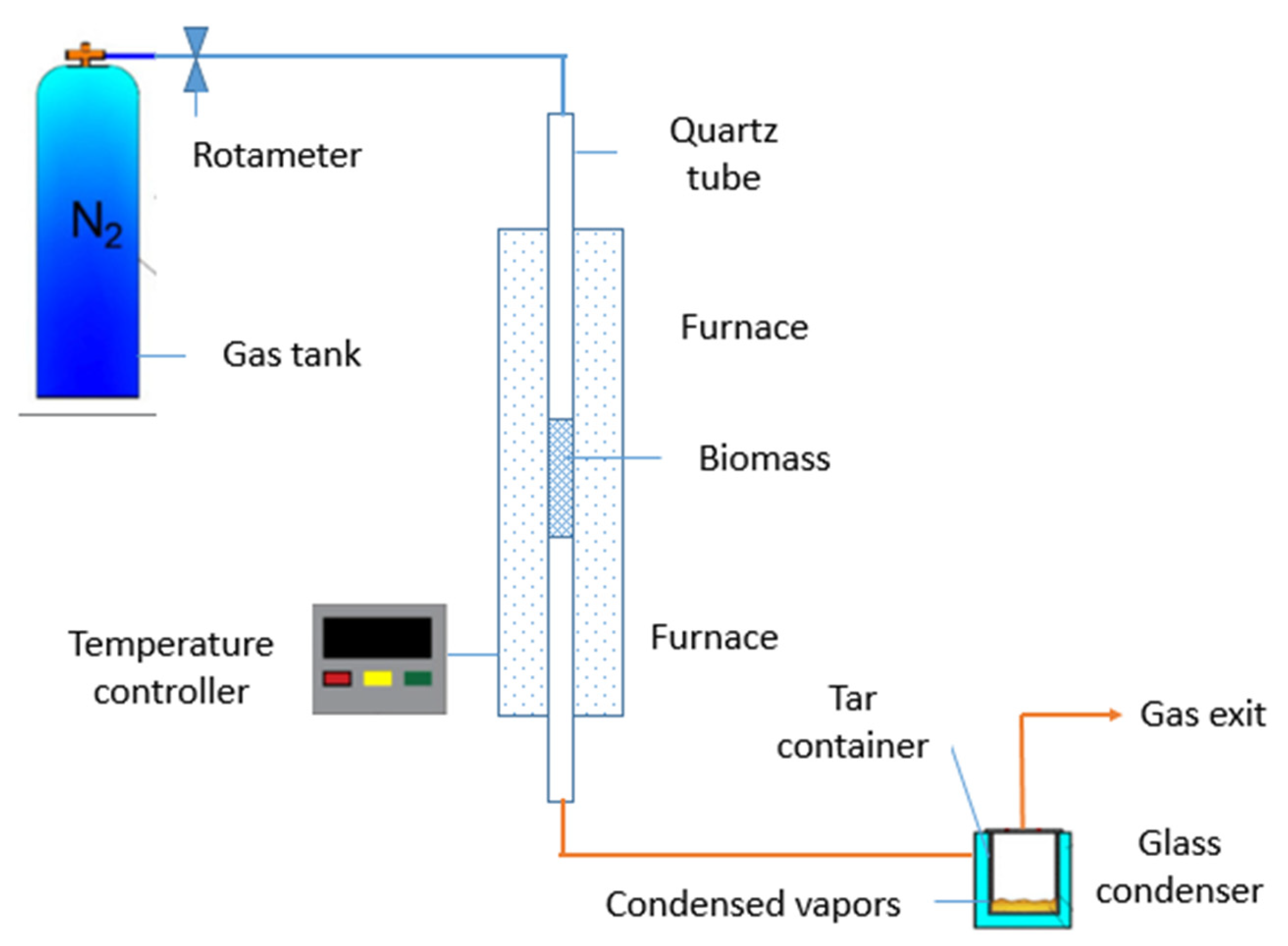
Figure 1. Schematic of the vertical batch pyrolysis system setup.
Preprints 105245 g001
Figure 2. Schematic of the horizontal batch pyrolysis system setup.
Preprints 105245 g002
Figure 3. HTC method and procedure to prepare hydrochar.
Preprints 105245 g003
Figure 4. EDX spectra of okara powder waste.
Preprints 105245 g004
Figure 5. SEM images of a) okara powder waste; b) Rice husk; c) coffee waste; d) shrimp shell; e) Rice straw; f) potato peels.
Preprints 105245 g005aPreprints 105245 g005b
Figure 6. SEM images of the biochars synthesized at (600 oC, 1 h) (a) okara biochar (OPW3) b); rice straw; c) rice husk (RH), d) coffee ground and e) potato peels (PP) at 1000 magnifications.
Preprints 105245 g006aPreprints 105245 g006b
Figure 7. Fourier Transform-Infrared spectra of different biomass.
Preprints 105245 g007
Figure 8. Fourier Transform-Infrared spectra of okara biomass and okara biochar.
Preprints 105245 g008
Figure 9. TGA-DSC analysis under N2 flow of okara powder waste.
Preprints 105245 g009
Figure 10. DSC and TGA analysis under N2 flow of okara powder waste by HTC method (OPW 4).
Preprints 105245 g010
Figure 11. Carbon yields and Burn-off of different experiments.
Preprints 105245 g011
Table 1. The synthesized samples and detailed pretreatment methods.
Biomass precursor Sample code Pretreatment methods Activating agent
Okara powder waste OPW1 Carbonization, 800 oC, in an Ar flow over 1h No activating
Okara powder waste OPW2 Carbonization at 650 oC in a gas N2 flow for 1 hour No activating
Okara powder waste OPW3 Carbonization at 600 oC in a gas N2 flow for 1 hour No activating
Okara powder waste OPW4 Hydrothermal carbonization at 200 oC; heating rate is 60 oC/h: temperature of 200 oC is maintained in 4h; weight ratio of OPW: water is 12.8 gram: 40 ml No activating
Okara powder waste OPW5 Hydrothermal carbonization at 200 oC; weight ratio is 12.8-gram OPW: 6.4 gr zeolite (4 mm in size): 40 ml water; a temperature of 200 oC is maintained in 4h; the heating rate is 60 oC/h: No activating
Okara powder waste OPW6 Hydrothermal carbonization at 200 oC, at a heating rate of 1 60 cC/hour, kept this 200 oC temperature for 4 hours.
Then Mix with KOH, and melamine with the mass ratio of hydrochar/KOH/melamine=1:4:2 and then perform the pyrolysis (two-step processes) at 600 oC; in a flow of N2 in 1h; N2 flow rate of 1 l/min
KOH, melamine (weight ratio of KOH: melamine = 2:1)
Okara powder waste OPW7 Carbonization 600 oC, N2, 1h to make biochar; after that biochar is mixed with KOH and water; then keep the sample for 48 hours in stirring, the ratio of biochar:KOH: water is 1:4:5 in weight, then filter and dry then calcined at 600 oC in N2 for 1h KOH
Rice husk RH Carbonization 600 oC, N2, 1h No activating
Okara powder waste OPW8 Carbonization 600 oC, N2, 1h; dry mixing process with KOH(ratio of biochar: KOH = 1.3) then dry at 120oC, then carbonization at 600 oC KOH
Okara powder waste OPW9 Carbonization 600 oC, N2, 1h; dry mixing process with KOH (ratio of biochar: KOH = 1.4) then dry at 120 oC, then carbonization at 600 oC KOH
Okara powder waste OPW10 Carbonization 600 oC, N2, 1h; then mix biochar:KOH: water ratio of 1:5:10; keep the sample for 5 days, filter, drying, calcine at 600 oC KOH
Table 2. Chemical composition of different biomass.
Elements Coffee waste Okara powder waste Rice straw Shrimp shell Rice husk Potato peels
Mass% Atom% Mass% Atom% Mass% Atom% Mass% Atom% Mass% Atom% Mass% Atom%
C 57.35 64.17 45.73 53.36 37.88 56.56 44.38 53.4 18.91 26.44 48.12 56.79
O 42.65 35.83 52.53 46.02 9.97 11.18 48.9 44.17 55.48 58.24 46.62 41.31
K 1.74 0.62 5.77 2.65 5.26 1.91
Ca 6.72 2.42
Si 46.37 29.61 55.61 15.31
Total 100 100 100 100 100 100 100 100 100 100
Table 3. Comparative details of this experiment’s specific capacitance of the okara-derived porous carbon with that of other studies in the literature.
Biomass precursor Sample code Pretreatment methods Activating agent SBET (m2/g) References
Firewood - Carbonization 850 °C Na2CO3/K2CO3 818 [41]
Banana peels - Hydrothermal 200 °C, 24 h No activating agent 294.6 [42]
Elephant grass, - Carbonization at 600 oC, in N2 flow; 1h KOH 407 [34]
Lotus leaf - Carbonization 500 oC, N2, 1h Melamine and KOH 687 [43]
Lotus leaf - Carbonization 500 oC, N2, 1h No activating agent 3.82 [43]
Lotus leaf - Carbonization 500 oC, N2, 1h Melamine 4.32 [43]
Okara powder waste OPW1 Carbonization, 800 oC, in an Ar flow over 1h No activating 1.16 This work
Okara powder waste OPW2 Carbonization at 650 oC in a gas N2 flow for 1 hour No activating 1.06 This work
Okara powder waste OPW3 Carbonization at 600 oC in a gas N2 flow for 1 hour No activating 20.73 This work
Okara powder waste OPW4 Hydrothermal carbonization at
200 oC; heating rate is 60 oC/h: temperature of 200 oC is maintained in 4h; weight ratio of OPW: water is 12.8 gram: 40 ml
No activating 7.01 This work
Okara powder waste OPW5 Hydrothermal
carbonization at
200 oC; weight ratio is 12.8-gram OPW: 6.4 gr zeolite 4 mm: 40 ml water; temperature of 200 oC is maintained in 4h; heating rate is 60 oC/h:
Zeolite (4 mm in size) 14.0 This work
Okara powder waste OPW6 Hydrothermal carbonization 200 oC and then pyrolysis (two-step processes) at 600 oC; in a low of N2 in 1h; N2 flow rate of 1 l/m KOH, melamine 22.04 This work
Okara powder waste OPW7 Carbonization 600 oC, N2, 1h to make biochar; after that biochar is mixed with KOH and water; then keep the sample for 48 hours, then dry at 120oC and calcine at 600oC in N2 flow (1l/min) KOH (ratio of biochar:KOH: water is 1:4:5 in weight) 104.32 This work
Rice husk RH Carbonization 600 oC, N2, 1h No activating 175.48 This work
Okara powder waste OPW8 Carbonization 600 oC, N2, 1h; dry mixing process with KOH KOH (mass ratio of OPW: KOH = 1/3) 212.60 This work
Okara powder waste OPW9 Carbonization 600 oC, N2, 1h; dry mixing process with KOH KOH (mass ratio of OPW: KOH = 1/4) 147.85 This work
Okara powder waste OPW10 Carbonization 600 oC, N2, 1h; then mix with KOH, biochar:KOH: water mass ratio of 1:5:10; keep the sample for 5 days KOH (with biochar:KOH: water ratio of 1:5:10; keep the sample for 5 days) 594.08 This work
Disclaimer/Publisher’s Note: The statements, opinions and data contained in all publications are solely those of the individual author(s) and contributor(s) and not of MDPI and/or the editor(s). MDPI and/or the editor(s) disclaim responsibility for any injury to people or property resulting from any ideas, methods, instructions or products referred to in the content.
Copyright: This open access article is published under a Creative Commons CC BY 4.0 license, which permit the free download, distribution, and reuse, provided that the author and preprint are cited in any reuse.
Prerpints.org logo

Preprints.org is a free preprint server supported by MDPI in Basel, Switzerland.

Subscribe

© 2024 MDPI (Basel, Switzerland) unless otherwise stated