Preprint
Article

Analysis and Optimization of Quantitative Casting Motion of a Casting and Pouring Robot

Altmetrics

Downloads

51

Views

18

Comments

0

This version is not peer-reviewed

Submitted:

30 April 2024

Posted:

30 April 2024

You are already at the latest version

Alerts
Abstract
According to the requirement of 20kg load of casting barrel, we design a three-dimensional model of the robot and analyze the three stages of liquid level change in the casting barrel during the casting process. Through the analysis, it is determined that the time and angle function is an implicit function, and it is impossible to find the analytical expression of time about angle. The kinetic function of the casting barrel is simulated by MATLAB, and it is found that the function image has mutation points, and when the original function is fitted and approximated by fifth-degree polynomial interpolation, the fifth-degree polynomial function image of the time versus the angular acceleration has a large amplitude of oscillation, especially the mutation points. A PID algorithm based on the discretization of the time and acceleration function is introduced for correction, and the results show that this method effectively reduces the oscillation amplitude of the image and improves the coincidence with the original function.
Keywords: 
Subject: Engineering  -   Mechanical Engineering

1. Introduction

Casting is the main method of obtaining the blanks of irregular and other difficult to process parts, widely used in industry, casting has a very important position in the field of machinery manufacturing. At present, the world, most of the casting operations are still completed by manual labor, but the casting workshop environment is harsh, the workers are exposed to high dust working environment for a long time, the health of the workers will be jeopardized, so the study of casting robots to replace manual labor is very meaningful.
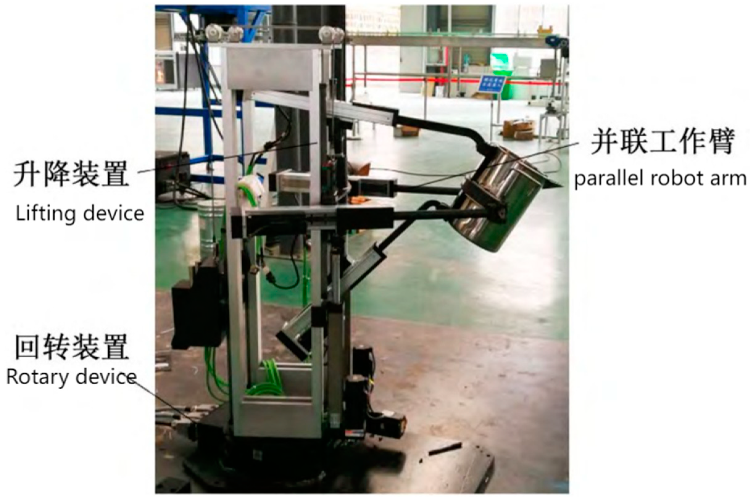
At present, most of the casting robots are still fixed in the workstation of the six degrees of freedom of the robotic arm to work, as shown in Figure 1:
But for casting robot arm, need to have a larger workspace, but also want to robot arm with fast and stable work effect. [1] However, the six degrees of freedom arm has many motors and a long structure, which will make the load smaller, and fixed at the workstation, which will make the workspace smaller, so there are still many areas for improvement in this aspect of the casting machine arm. In order to solve the problem of casting robot load small Wang Chengjun et al. proposed a four-degree-of-freedom parallel casting robot with chassis, as shown in Figure 2:
To a certain extent, to solve the problem of small workspace and low load of six-degree-of-freedom robotic arm. But it is a fully parallel connected robot, although the load capacity is high, but the requirements for the robot installation accuracy is very high, as well as for the control of the requirements of the accuracy is also high [3,4,5].
Wang Peng et al. design a four degrees of freedom parallel robot, the advantage is that the parallel arm load capacity is strong, the disadvantage is that the control precision requirements are high, for the design of high load casting robot has reference value [6,7,8]. In recent years, there are also a lot of casting robot invention patents, which provide a reference for the design of casting robot [9,10]. Casting workshop environment is harsh, Lei Xianhua et al. design a semi-automatic fixed-point casting table, which has reference value for the kinematic analysis of casting robot fixed-point casting [11]. Fixed-point casting means that the flow rate q is a fixed value.For the quantitative casting problem, in the casting of copper anode there are a number of studies show that the use of PID algorithms can improve the accuracy, which provides a reference for the casting robot quantitative casting analysis [12,13,14].

2. Dynamic Analysis of Casting Barrel

2.1. Robot 3D Modeling

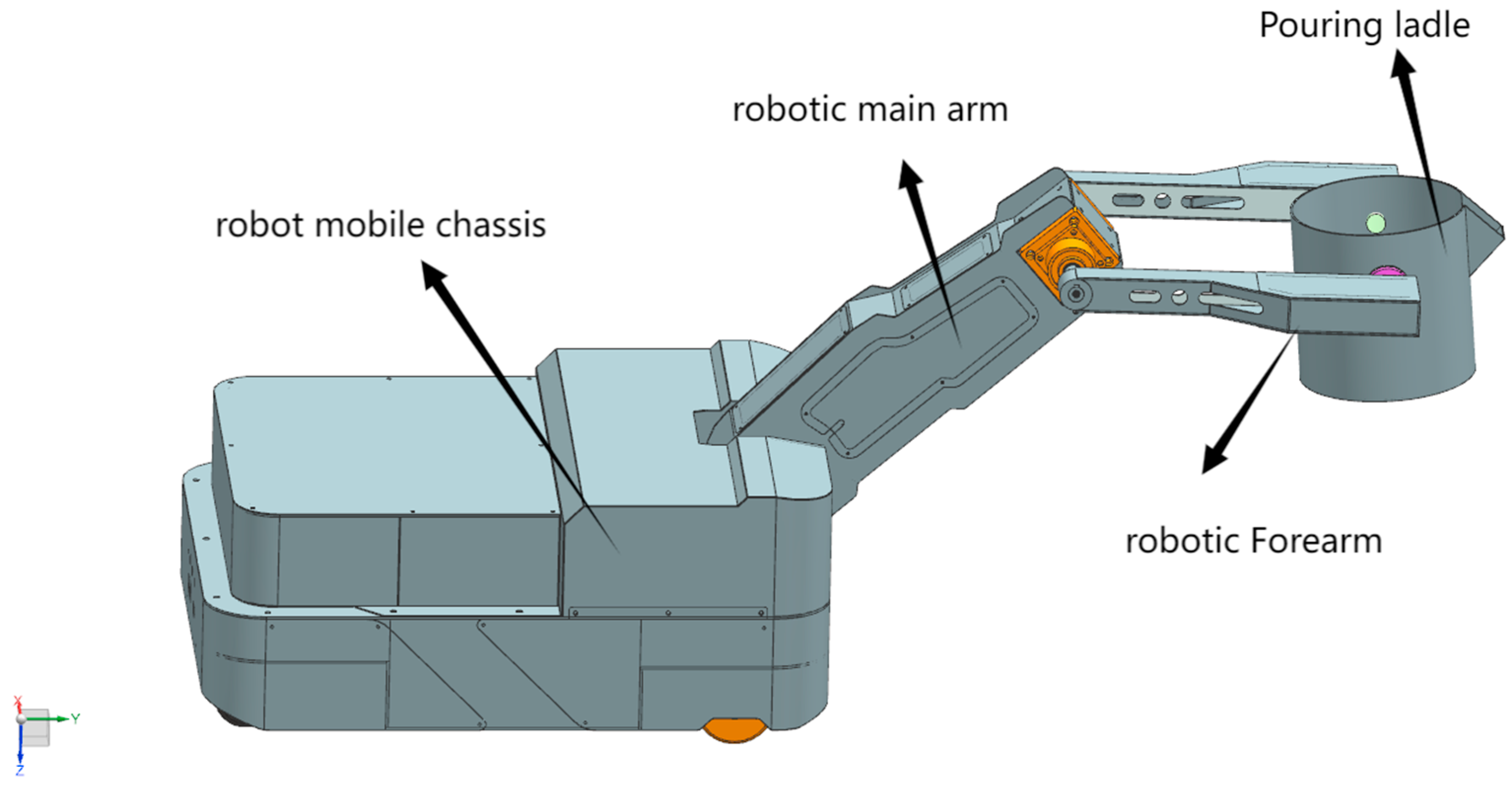
As shown in Figure 3
The casting robot consists of a movable chassis and a robotic arm, which includes a big arm, a small arm and a casting bucket. The robot works in the following way: first move the chassis to the designated station by operation, then control the robot's big arm and small arm to make the pouring bucket aligned with the pouring hole, and finally control the rotation of the bucket to complete the quantitative pouring.

2.2. Differential Analysis of the Mouth of a Casting Barrel

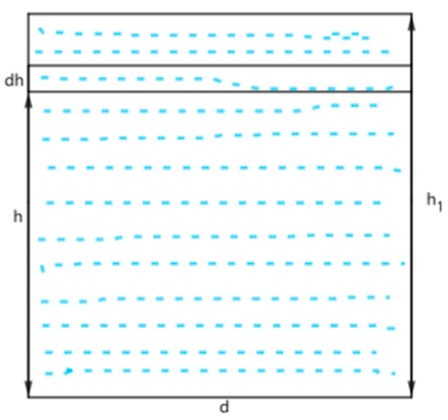
The cross section of the liquid is rectangular when the aluminum water flows out of the nozzle, and the cross section is taken as shown in Figure 4
When the aluminum water flows out of the pouring ladle, the liquid level of the aluminum water will exceed the tip of the pouring ladle mouth by a certain height h1 . Neglecting the flow rate of the liquid brought by the rotation of the pouring ladle, the flow rate of the aluminum water at this time will come from the work done by the pressure on the liquid surface. Let the width of the sprues of the pouring ladle be d. Differential analysis of the flow rate is carried out on the cross-section.
The velocity v of the liquid at height h is:
v = 2 g ( h 1 h )
At this point the flow rate q is:
q = 0 h 1 v · d · d h
The above velocity v is only for deriving the kinetic energy that can be brought about by the liquid surface pressure, the actual velocity v1 of the cross section is:
v 1 = q d · h 1 = 2 2 g · h 1 3

2.3. Analysis of the Casting Drum Angle as a Function of the Remaining Volume of Liquid

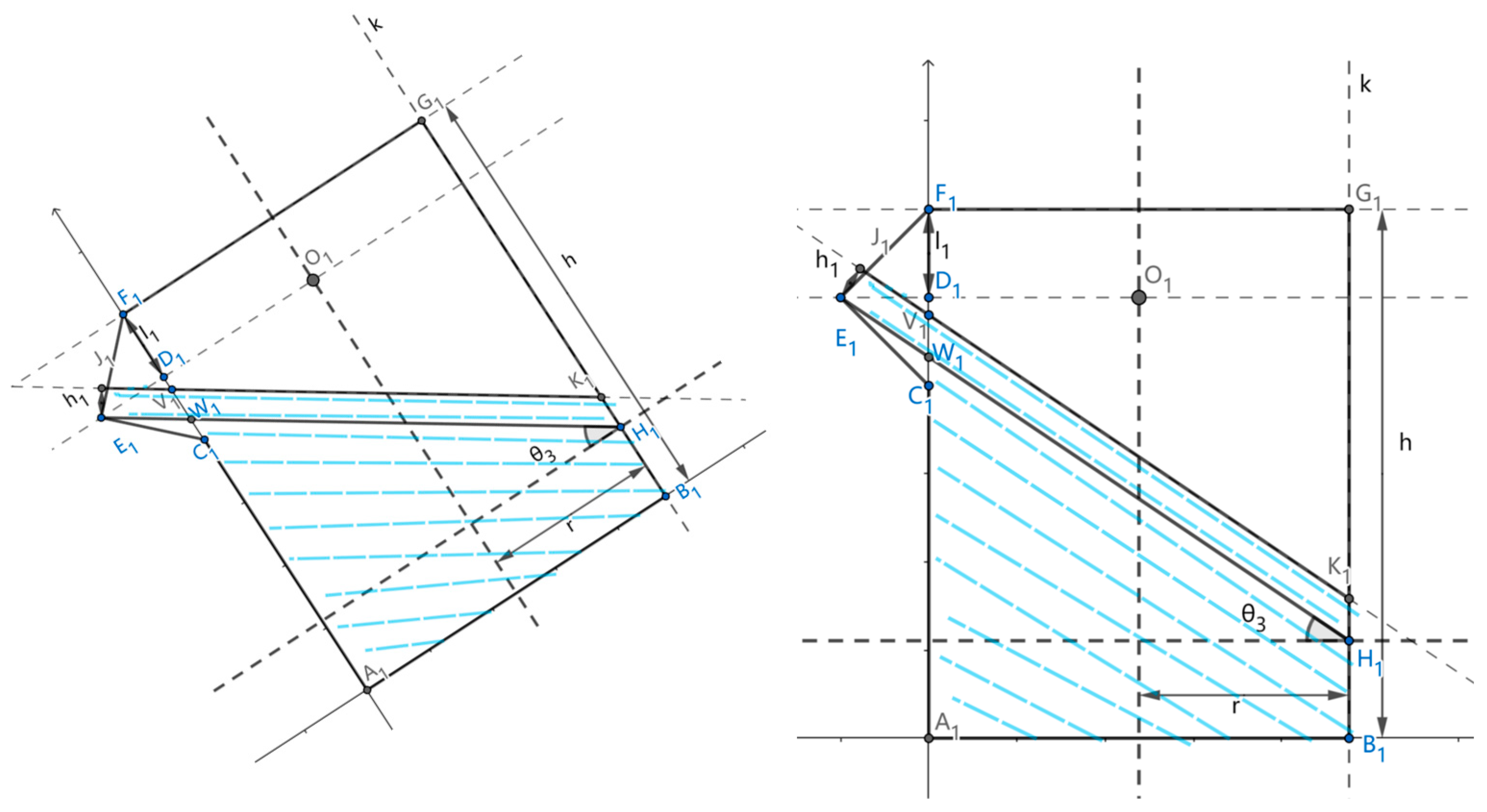
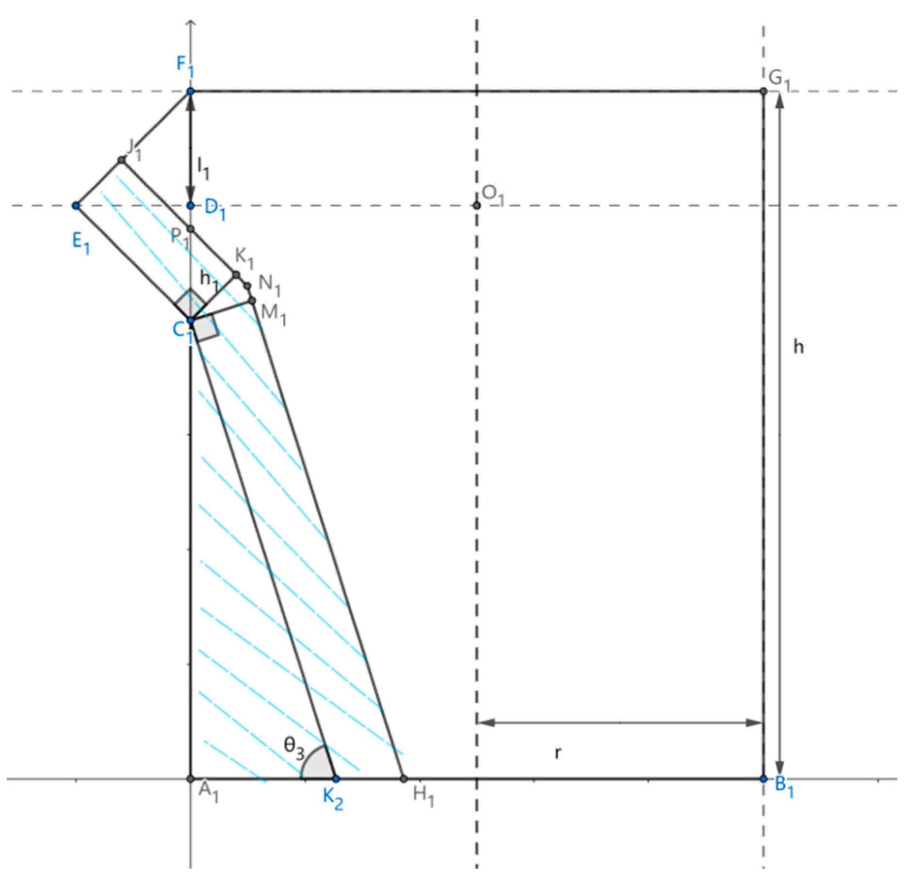
This is because the flow rate q has to be constant. From the above equation, it can be seen that the exit velocity v1 and the height of the liquid surface should also be a constant value. From this, it can be deduced that the casting ladle in the rotation of different angles, the remaining liquid volume in the casting ladle, and then deduce the angle and the remaining liquid volume relationship formula. Relative motion analysis method, the actual situation is the casting barrel rotation, the liquid level to maintain the level. The analyzing process can be regarded as the bucket does not move, the liquid inside the ladle is divided into three stages with the change of angle, the stages are as shown in Figure 5.
Triangle E1F1C1is an isosceles right triangle, and the rotation angle of the casting bucket is   θ 3 of the casting bucket is in the range of 0 π 4 . A1 for the origin, A1B1for the x-axis, A1F1 for the y-axis,perpendicular to the direction of this surface inward for the z-axis. The area formed by the liquid surface and the sprue is the area corresponding to the polygon J1E1C1A1B1 Kin the sprue in the figure. J1E1C1V1 corresponds to the area of the sprue nozzle, which is a projection on a triangular prism.
W1 with coordinates (0, h l 1 ( 1 + tan θ 3 ) ,0)
E1 Coordinates are (- l 1 , h l 1 ,0)
V1 coordinates of (0, h l 1 ( 1 + tan θ 3 ) + h 1 cos θ 3 , 0 )
J1 Coordinates are (- l 1 + h 1 · sin θ 3 , h l 1 + h 1 cos θ 3 ,0)
C1 coordinates of (0, h 2 l 1 , 0 )
It can be introduced that J1E1C1V1 corresponds to the volume V2 as:
V 2 = ( 2 l 1 h 1 · sin θ 3 2 + h 1 cos θ 3 l 1 tan θ 3 h 1 cos θ 3 2 + l 1 tan θ 3 ) · h 1 · d + l 1 2 · 1 sin θ 3 · d 2
Calculate the volume of A1B1K1V1 corresponding to the corresponding cylinder. V 3 Here, the ternary integral can be used to calculate.
The surface equation of the cylinder is: x r 2 + z 2 = r 2 The equation corresponding to the straight line V1K1 is:
h l 1 ( 1 + tan θ 3 ) + h 1 cos θ 3 x tan θ 3 = y
It can be introduced that the volume of A1B1K1V1 corresponding to the corresponding volume in the cylinder V 3 is:
V 3 = 0 2 r 0 h l 1 ( 1 + sin θ 3 ) + h 1 cos θ 3 x tan θ 3 r 2 x r 2 r 2 x r 2 d z d y d x
To simplify the problem, when θ 3 = 45 ° , let K1 coincide with B1 , when there is:
h l 1 + 2 h 1 2 = 2 r + l 1 2 h 1 2
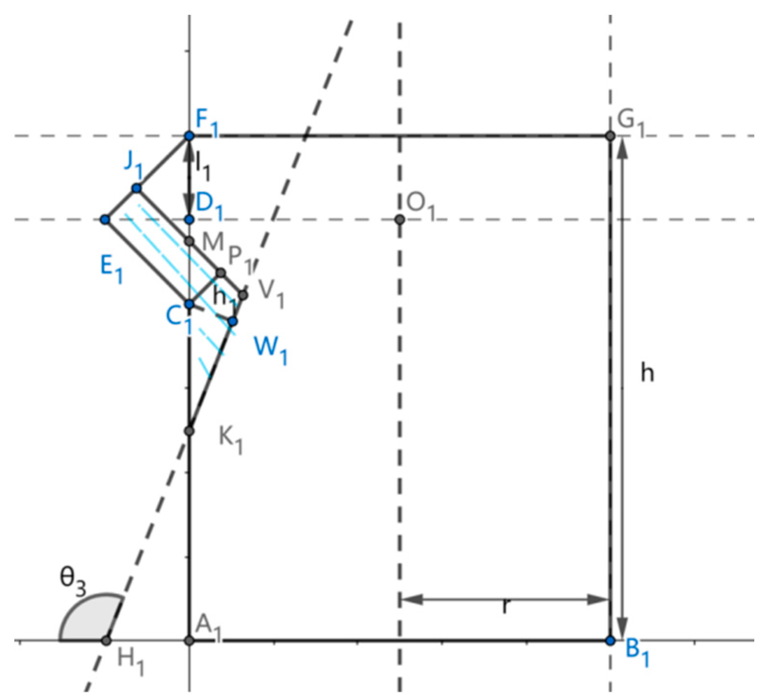
The second stage of the casting drum is analyzed below, as shown in Figure 6
Following the first stage of the analysis J1E1C1P1 Within the triangular prisms
E1 Coordinates are (- l 1 , h l 1 ,0)
C1 coordinates of (0, h 2 l 1 , 0 )
J1 Coordinates are (- l 1 + 2 h 1 2 , h l 1 + 2 h 1 2 ,0)
P1 with coordinates (0, h 2 l 1 + 2 h 1 , 0 )
The volume V2 corresponding to J1E1C1P1 can be introduced as:
V 2 = 2 2 l 1 · h 1 · d h 1 2 · d 2
P1N1H1A1 within the cylinder
The coordinates of H1 are ( h 2 l 1 tan θ 3 + h 1 cos θ 3 ,0,0)
The linear equation of H1N1 is:
tan θ 3 · x h 2 l 1 tan θ 3 h 1 sin θ 3 = y
The linear equation of J1N1 is:
x = y h + 2 l 1 2 h 1
The point of intersection of the two lines N1 has the horizontal coordinates of h 2 l 1 tan θ 3 + 2 h 1 · sin θ 3 h 1 sin θ 3 tan θ 3 · sin θ 3
N1 The corresponding ternary integral on the left V 31 for:
V 31 = 0 h 2 l 1 tan θ 3 + 2 h 1 · sin θ 3 h 1 sin θ 3 tan θ 3 · sin θ 3 0 h 2 l 1 + 2 h 1 x r 2 x r 2 r 2 x r 2 d z d y d x
N1 The corresponding ternary integral on the right-hand side V 32 for:
V 32 = h 2 l 1 tan θ 3 + 2 h 1 · sin θ 3 h 1 sin θ 3 tan θ 3 · sin θ 3 h 2 l 1 tan θ 3 + h 1 cos θ 3 0 tan θ 3 · x h 2 l 1 tan θ 3 h 1 cos θ 3 r 2 x r 2 r 2 x r 2 d z d y d x
The above formula can be applied until H1 and A1 coincide, at which time the rotation angle of the sprue is   θ 3 :
θ 3 = sin 1 h 1 h 2 l 1 + π 2
Therefore the range of values for the angle of rotation of the Stage 2 casting ladle is ( π 4 , sin 1 h 1 h 2 l 1 + π 2 ).
Phase III analysis is shown in Figure 7
The area corresponding to J1E1C1M1 in the figure remains consistent with the volume V2 in Stage II for:
V 2 = 2 2 l 1 · h 1 · d h 1 2 · d 2
And the region inside the cylinder can be utilized with the known conditions in stage 2, the corresponding ternary integral V 3 for:
V 3 = 0 h 2 l 1 tan θ 3 + 2 h 1 · sin θ 3 h 1 sin θ 3 tan θ 3 · sin θ 3 tan θ 3 · x h 2 l 1 tan θ 3 h 1 sin θ 3 h 2 l 1 ( 1 + sin θ 3 ) + 2 h 1 x r 2 x r 2 r 2 x r 2 d z d y d x
At this point   θ 3 The corresponding range of values should be ( sin 1 h 1 h 2 l 1 + π 2 , 3 π 4 ), because when   θ 3 is 3 π 4 when the spout of the pouring ladle is already perpendicular to the ground, continuing to increase the angle of inclination will cause the spout to lose the effect of diversion. At this time also happens to be the liquid out of the vertical downward flow. The fact that the dosing requirement cannot be maintained for a short period of time at the beginning and the end of the casting process is unavoidable and has no effect on the casting process. Finally, the ladle is allowed to rotate at an angle of 3 π 4 to allow the aluminum to flow out naturally.
After the above three stages of analysis, the relationship between the angle of rotation of the ladle and the liquid remaining in the ladle can be obtained as follows. V 4 θ 3 The initial volume is denoted as The initial volume is written as V 0 Then the flow rate can be obtained, because the flow rate is a constant value c so there is:
V 4 θ 3 t = c t
From the formula with its derivation process, it can be seen that the direct expression of angle and time belongs to the implicit function, and it is difficult to derive the formula. At the same time in the control of casting barrel casting, also can not input such a complex function, this time need to be simulated to fit the relationship between angle and time.

2.4. Selection and Description of Design Parameters for Casting Drums

The casting drum parameters are shown in Table 1 below
According to the formula
V 1 = m ρ
where V 1 is the volume of aluminum water, m is the mass of aluminum water, and the density of aluminum water is taken as ρ = 2.375 g/cm3. The volume can be found to be   V 1 is about 8421cm3. Take the diameter of the bottom surface of the barrel for 24cm, at this time the barrel bottom area S2 is about 452cm2 . At this time 20kg of aluminum water in the casting barrel liquid surface height h2 for:
h 2 = V 1 S 2 = 8421 c m 3 452 c m 2 18.63 c m
The required casting time is taken as T=30s, at which time the flow rate q can be obtained:
q = V 1 T = v 1 · d · h 1 = 2 2 g · h 1 3 · d · h 1 = 280.7 c m 3 / s
According to the above formula we can find h 1 According to the formula, the height of the barrel h = 25.5 cm. In order to prevent the aluminum water from splashing out during the transportation of aluminum water, there should be
h 2 l 1 = 19.5 c m > h 2 = 18.63 c m
Therefore, the parameters of the drum are in accordance with the design requirements.

3. Simulation of Casting Drum Mechanics with Fifth-Degree Polynomial Interpolation and Fitting Approximation

3.1. Simulation and Analysis of Casting Drum Dynamics

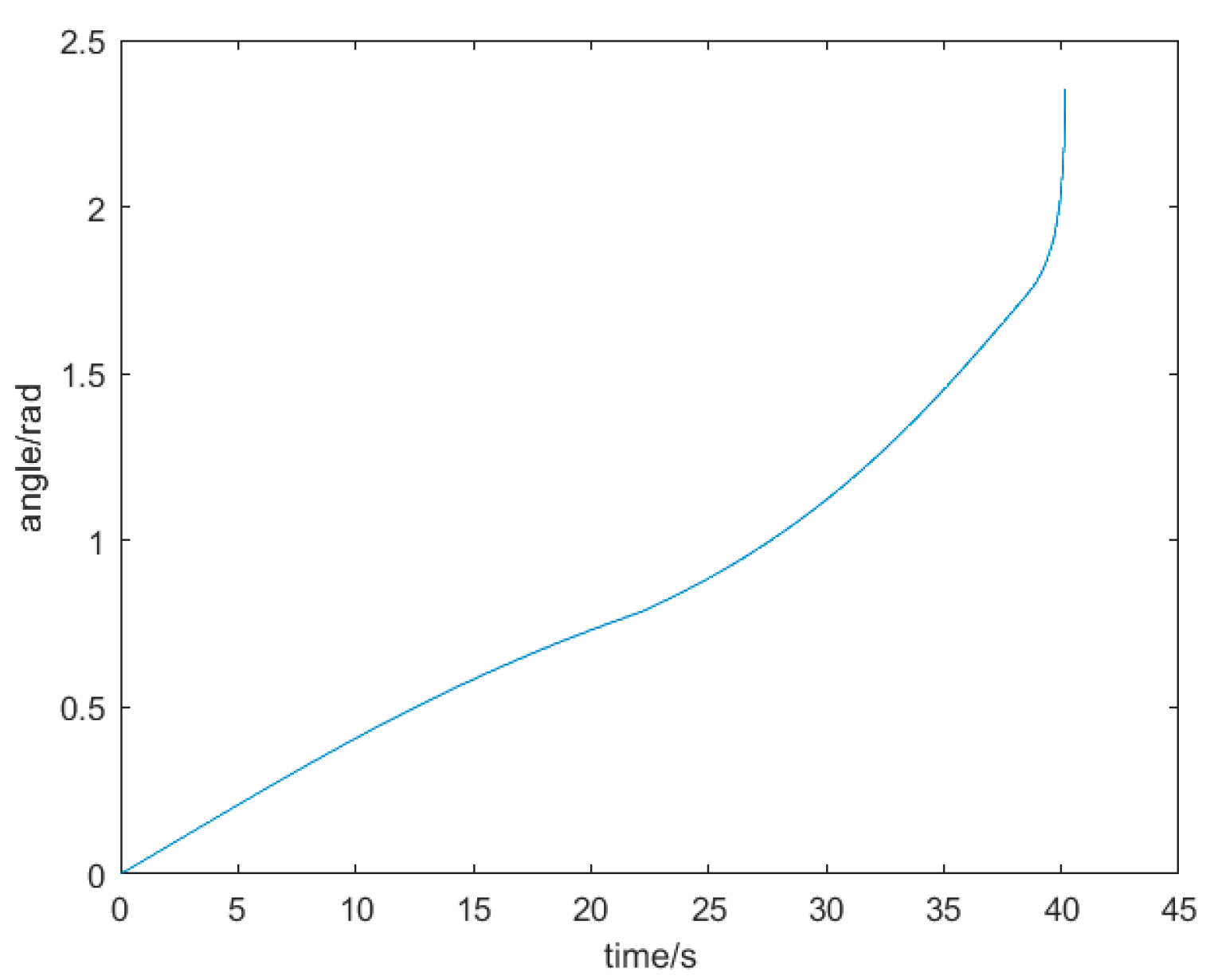
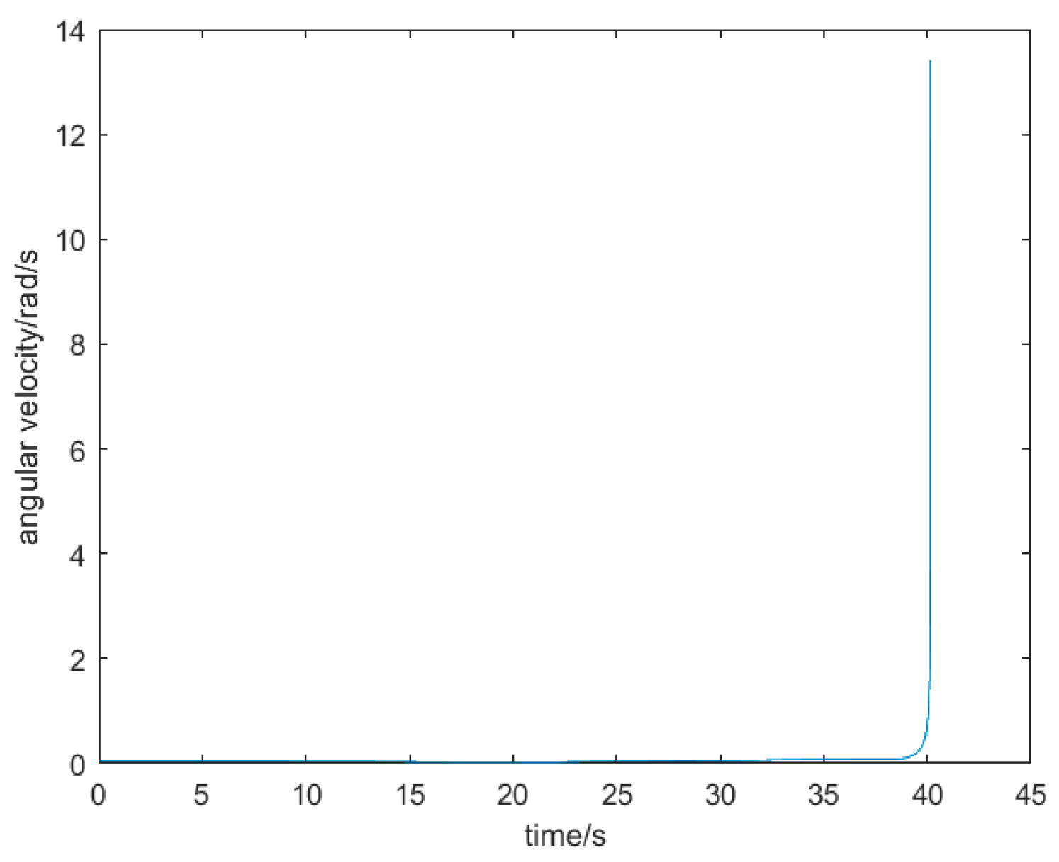
Based on the above parameters, the dynamics of the casting drum is simulated using MATLAB, and the function images can be obtained as shown in Figure 8 and Figure 9:
Since the pouring bucket is a dosed pouring method, only a 30s time period needs to be selected for pouring. Near the time 0s region the initial level of aluminum water in the pouring bucket will be very high and is not suitable for selection. Close to 40s, the speed change is too large, also not suitable for selection. Can choose the time period of 5s-35s, at the same time, the function image near 40s will be discarded. Can get the following Figure 10 function image.
From left to right are the images of time as a function of angle, angular velocity, and angular acceleration, and from the images, it can be seen that there is a sudden change in the image of the time as a function of angular acceleration and the image of the time as a function of angular velocity. This is due to the fact that when the rotation angle of the casting barrel is less than 45 degrees, as shown in Figure 5, the liquid surface of aluminum water is rotating around the point E1 . When the barrel rotates more than 45 degrees, as shown in Figure 6, the surface of the aluminum water rotates around the point N1 , which is the reason for the sudden change. Although there is a mutation, as shown in the figure but due to the peak acceleration of the mutation value a<0.016rad/s2 , this mutation value is very small and does not affect the motor work.

3.2. Fitted Approximation with Fifth Degree Polynomial Interpolation

Since the analytical expression cannot be derived for the time and angle functions, the rotational trajectory of the casting bucket is approximated by fitting an interpolation curve with a fifth degree polynomial in order to facilitate the control of the rotation of the bucket. The rotation angle of the casting bucket is divided into n segments, and the time range of the nth segment is t n t t n + 1 .
Depending on the casting barrel time as a function of angle θ 3 t There:
Angle   constraints : θ 3 n t n = θ 3 t n θ 3 n t n + 1 = θ 3 t n + 1
Angular   velocity   constraints : θ 3 n ˙ t n = θ 3 ˙ t n θ 3 n ˙ t n + 1 = θ 3 ˙ t n + 1
Angular   acceleration   constraints θ 3 n ¨ t n = θ 3 ¨ t n θ 3 n ¨ t n + 1 = θ 3 ¨ t n + 1
The generalized formula is:
θ 3 n t = a 3 n 0 + a 3 n 1 t + a 3 n 2 t 2 + a 3 n 3 t 3 + a 3 n 4 t 4 + a 3 n 5 t 5
Substituting six constraints there:
θ 3 t n = a 3 n 0 + a 3 n 1 t n + a 3 n 2 t n 2 + a 3 n 3 t n 3 + a 3 n 4 t n 4 + a 3 n 5 t n 5 θ 3 t n + 1 = a 3 n 0 + a 3 n 1 t n + 1 + a 3 n 2 t + 1 2 + a 3 n 3 t n + 1 3 + a 3 n 4 t n + 1 4 + a 3 n 5 t n + 1 5 θ 3 ˙ t n = a 3 n 1 + 2 a 3 n 2 t n + 3 a 3 n 3 t n 2 + 4 a 3 n 4 t n 3 + 5 a 3 n 5 t n 4 θ 3 ˙ t n + 1 = a 3 n 1 + a 3 n 2 t n + 1 + a 3 n 3 t n + 1 2 + a 3 n 4 t n + 1 3 + a 3 n 5 t n + 1 4 θ 1 ¨ t n = 2 a 3 n 2 + 6 a 3 n 3 t n + 12 a 3 n 4 t n + 20 a 3 n 5 t n 3 θ 3 ¨ t n + 1 = 2 a 3 n 2 + 6 a 3 n 3 t n + 1 n + 12 a 3 n 4 t n + 1 2 + 20 a 3 n 5 t n + 1 3
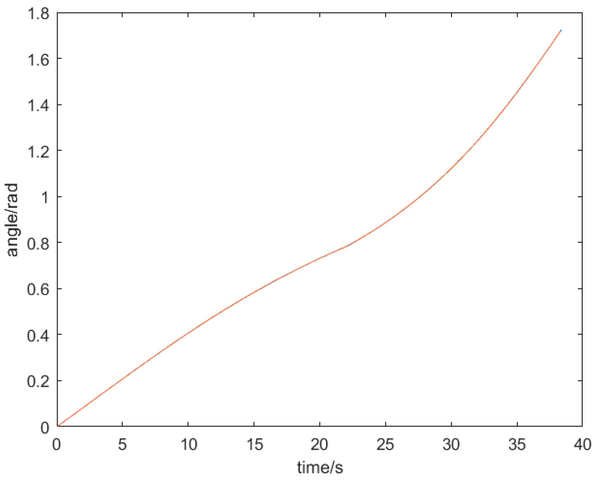
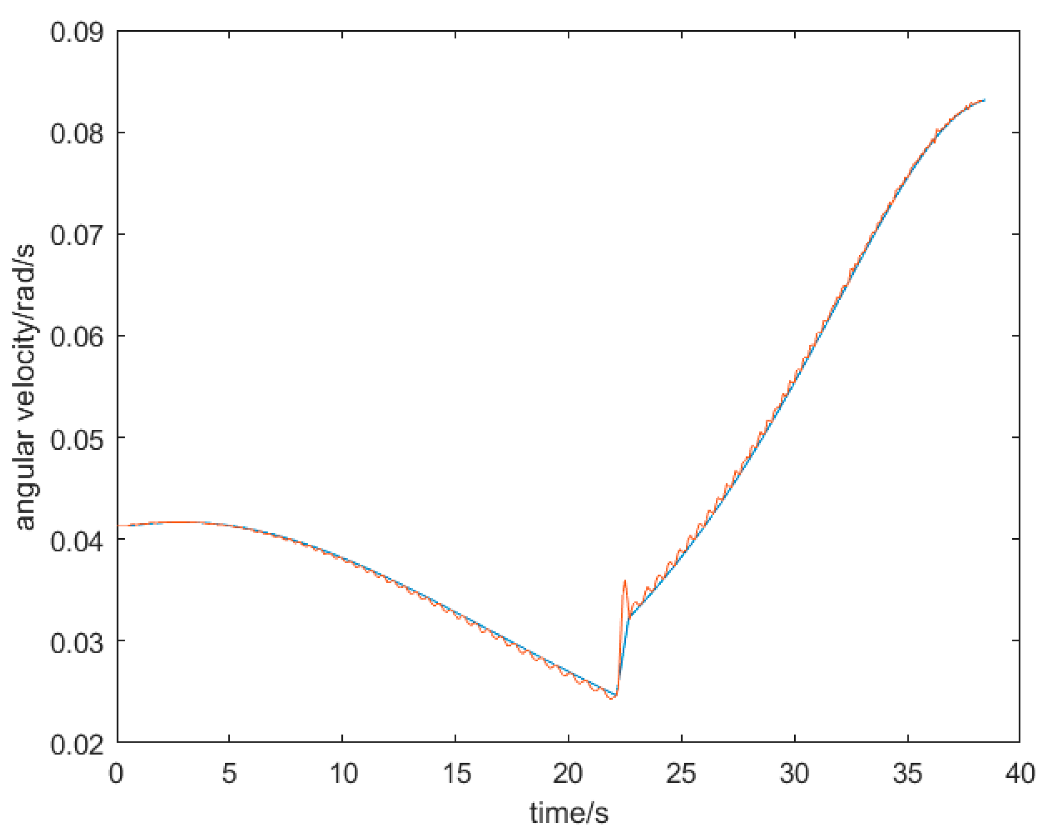
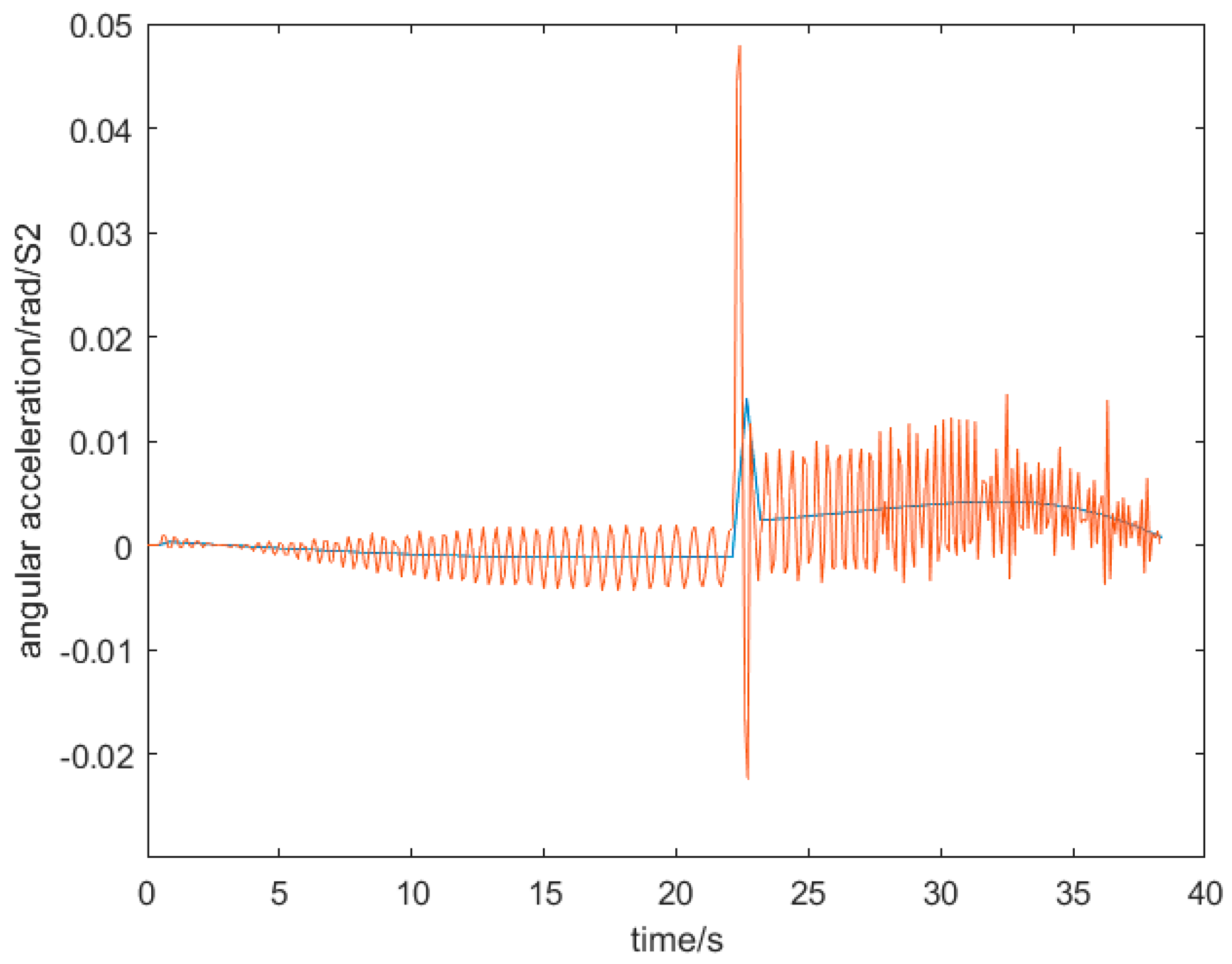
The casting barrel angle is chosen from 0-100 degrees, which is divided into 100 segments, each segment corresponding to 1 degree. Simulation using MATLAB can be obtained as shown in Figure 11, Figure 12 and Figure 13 function images
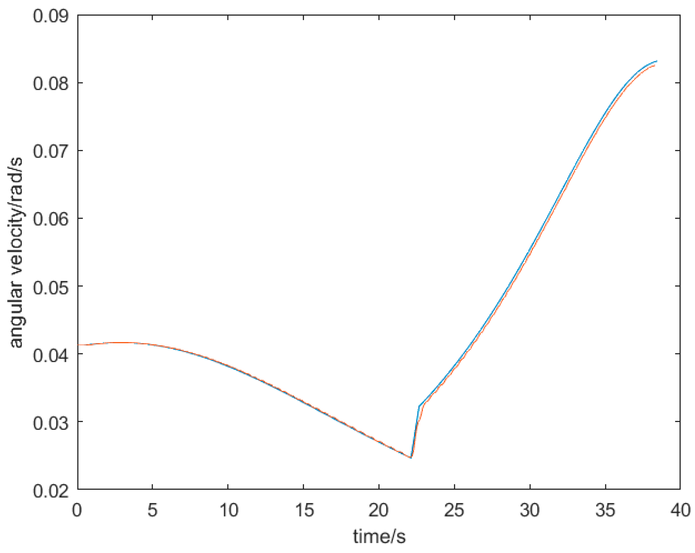
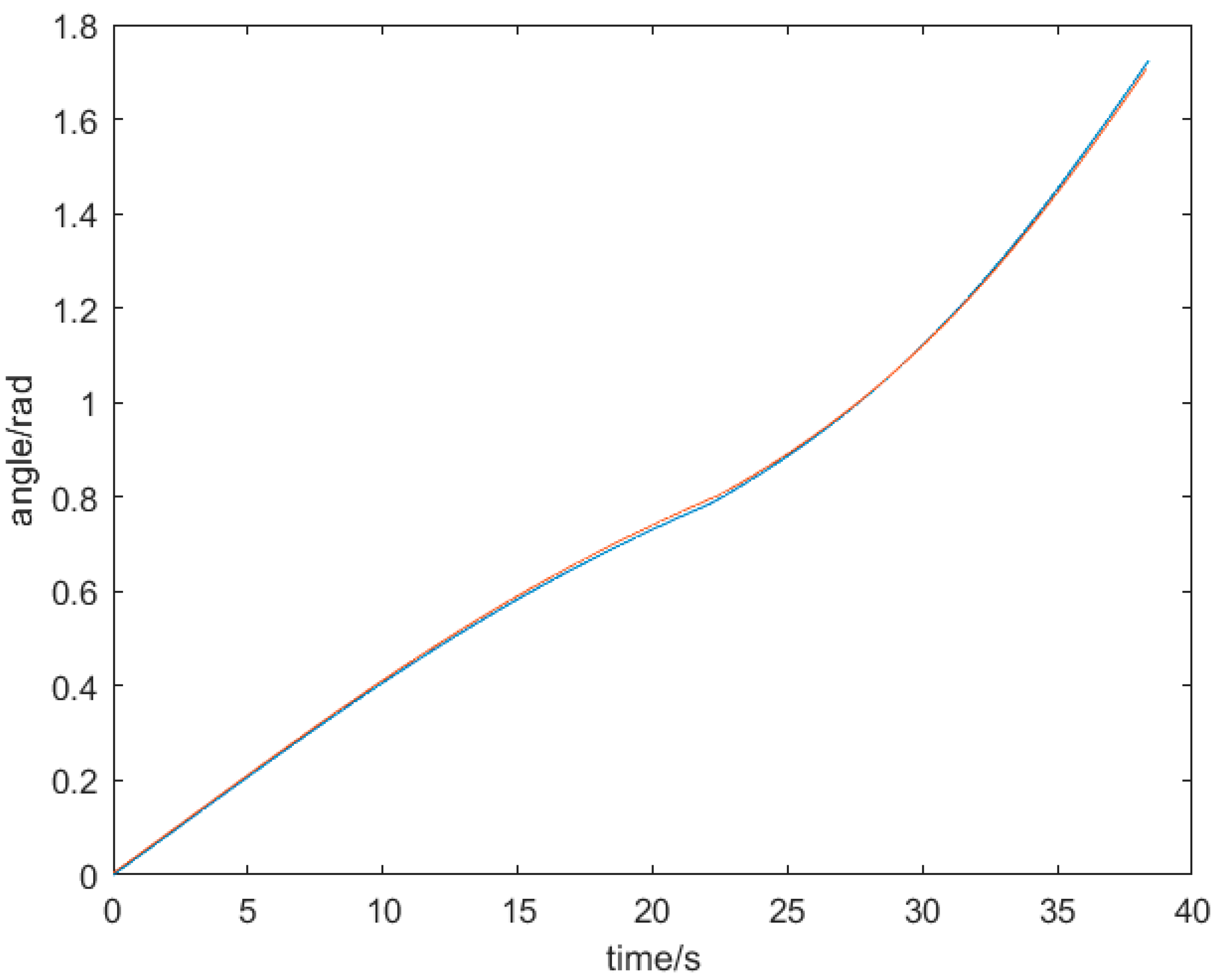
In the figure, the blue curve represents the image of the original function and the red curve represents the image of the approximating function for a fifth degree polynomial. It can be seen that in the plot of the function of time versus angle, the original function and the approximation function are basically the same. In the plot of time versus angular velocity function, the approximation curve is basically convergent, but there are small fluctuations at the mutation points. In the plot of time versus angular acceleration, the approximation curve is oscillating compared to the original function, and there are large oscillations at the mutation points.

3.3. PID Algorithm Based on Discretization of Time and Angular Acceleration

For the problem of simulating curvilinear oscillations, the time versus acceleration function in the fifth degree polynomial is first discretized, again by splitting the original function into 100 segments by performing it every 1 degree. At the nth segment, the time versus angular acceleration function starts at ( t n , θ 3 n ¨ t n ), and the end point is ( t n + 1 , θ 3 ¨ t n + 1 ). The line segment connected between these two points is approximated as the original function. The generalized formula for the time versus angular acceleration function is given by Equation 15
θ 4 n ¨ t = θ 3 ¨ t n + 1 θ 3 ¨ t n t n + 1 t n ( t t n ) + θ 3 ¨ t n
Thus the error generated by the oscillations is given by Eq:
ε n ( t ) = θ 4 n ¨ t θ 3 n ¨ t
In order to minimize the oscillations, the P and D algorithms can be added for correction, at which point the approximation function of time versus angular acceleration after the fifth degree polynomial correction is:
θ 5 n ¨ t = θ 3 n ¨ t + K p ε n ( t ) + K d ε n ( t ) ˙
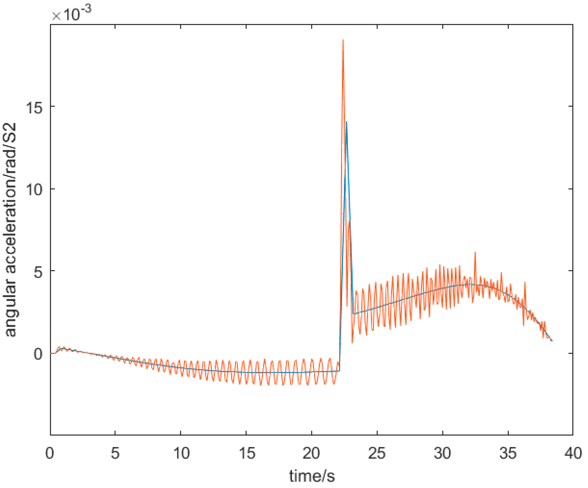
K p with K d are the parameters to regulate the oscillation of the simulation function, after the parameters are adjusted, when K p = 0.7, and K d = 0.1, the corrected time about acceleration simulation image is shown in Figure 14:
Comparing the plots, it can be clearly seen that the amplitude of the simulated function oscillations is significantly reduced, and the overlap of the function image with the original function at the mutation point is significantly improved. According to the corrected time about angular acceleration graph to derive the function of time versus angular velocity and the function of time versus angle are shown in Figure 15 and Figure 16
Based on the images, it can be seen that this modified simulation function fits better than the fifth-degree polynomial interpolation function, which can effectively avoid the problem that the interpolation function will amplify the original function when there is a mutation in its existence.

4. Experiment

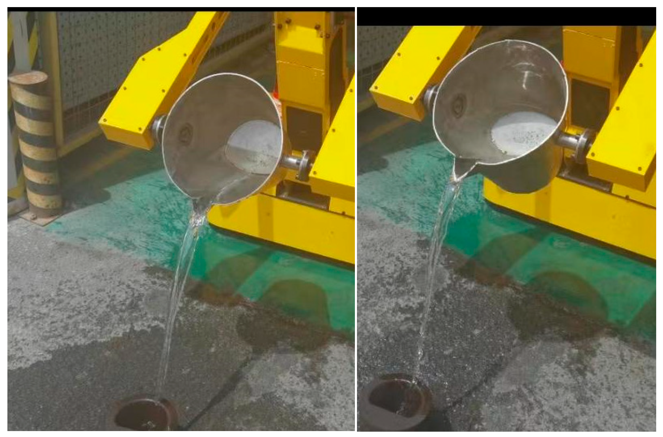
In order to verify the correctness of the casting bucket trajectory planning, therefore experiments were done for quantitative casting casting.
As shown in Figure 17, these are some photos taken during the test of quantitative casting versus spot casting. To ensure safety, water was used instead of aluminum water for the experiment. Under high temperature, the viscosity coefficient of aluminum water is similar to that of water, the servo motor can directly control the rotation speed, and the difference between the density of aluminum water and water is irrelevant, so it is completely feasible to use water instead of aluminum water for the experiment.
Casting time selection 0-35 seconds, the first 5 seconds, for the acceleration time, so that the casting barrel slowly accelerated to 5 seconds to meet the quantitative casting speed required. Because the casting bucket level is the initial state, and the water is not full. For the first five seconds, the bucket rotates and no water flows out. Starting from the fifth second and ending at the 35th second, it takes 30 seconds to complete the casting of a volume of 8421cm3 of water. This volume corresponds to the volume of 20kg of aluminum water. Starting from the 5th second, take a picture every 2 seconds to record the volume of water flowing out of the casting bucket, and then subtract the previous one from the back scale volume to get the volume of water flowing out every 2 seconds. The experimental data are shown in Table 2 below:
The volume of water casting is 8424.9cm3, and 8421cm3, the error is 3.9cm3, if fully meet the requirements of quantitative casting, every two seconds to increase the volume of 561.4cm3, from the table can be seen from the fifth to the seventh second, just started casting two seconds, the volume of water flow out of the small, which may be the beginning of the casting of the water, the liquid level did not reach the predetermined height, resulting in the water flow out of the small. This may be due to the fact that when the water is first poured, the liquid level does not reach a predetermined height, resulting in a small initial velocity when the water flows out of the mouth of the pouring bucket, so the volume of water flowing out in the first two seconds is on the small side. From the 7th to the 9th second, the increased volume is on the large side compared to 561.4cm3, this is due to the small volume of the water flowing out in the first 2 seconds, which therefore leads to a rise in the liquid level from the 7th to the 9th second, allowing the velocity to increase by a small amount, and therefore the volume of water flowing out from the 7th to the 9th second is on the large side. From the 7th to the 21st second, the volume of water flowing out first fluctuates and then stabilizes close to the ideal value. This is because the period from the 7th to the 21st second corresponds to the rotation angle of the casting barrel between 0 and 45 degrees. From the analysis of the casting barrel stage, the size and direction of the liquid velocity out of the mouth of the casting barrel are theoretically constant within the range of 0 to 45 degrees. From the image of the simulation curve, the function images corresponding to the range of 0-45 degrees of the rotation angle of the casting barrel are relatively stable, and the error is small. Therefore, such experimental data are in line with expectations. From the 21st to the 23rd second, the error of the volume of water flowed out is larger than that from the 19th to the 21st second, which is due to the mutation point of the rotation angle of the casting barrel, so the error near the mutation point is slightly larger, but this error is very small compared to the total volume, and at the same time, the total error is relatively small, therefore, the error at the mutation point has very little effect. Comparing the experimental data from 27 seconds to 35 seconds with that from 11 seconds to 19 seconds, it is clear that the error is smaller in the 11 seconds to 19 seconds and larger in the 27 seconds to 35 seconds. From the fitted curve image, this period of time corresponds to the range of 46-100 degrees of rotation of the casting barrel, which corresponds to the oscillation of the curve as a function of time and angular acceleration, whereas the range of 0-45 degrees is more stable, which results in a smaller error in the range of 11 to 19 seconds than in the range of 27 to 35 seconds. But the errors are always within acceptable limits.

4. Conclusion

According to the three-dimensional model of the casting barrel of the casting robot, the functional relationship between the rotation angle of the casting barrel and the remaining volume is analyzed, and the function image of time about the rotation angle is obtained through MATLAB, and the function image has an abrupt change and the analytical expression cannot be derived. After the interpolation approximation by a fifth degree polynomial, the interpolated function was found to have the problem of large oscillation amplitude in the image of the function of time about angular acceleration. A PID algorithm based on the discretization of time with respect to angular acceleration is used to correct the fifth degree polynomial, and the results show that this method is feasible, effectively improves the function overlap, and provides a good fit at the mutation points. Finally, the correctness of the optimized curves was verified experimentally.This is of some reference value for designing the motion trajectory of the casting bucket of a casting robot.

Acknowledgments

We would like to thank Mr. Xia Jianqiang for his support of this project.

References

  1. Kim, R., Balakirsky, S., Ahlin, K., Marcum, M., and Mazumdar, A. (January 22, 2021). "Enhancing Payload Capacity With Dual-Arm Manipulation and Adaptable Mechanical Intelligence." ASME. J. Mechanisms Robotics. April 2021; 13(2): 021012. [CrossRef]
  2. Ren Runrun. Structural design and performance analysis of movable casting robot in complex environment[D]. Anhui University of Technology,2019.
  3. Xu Chengke. Design and research of heavy-duty casting robot execution system[D]. Anhui University of Technology,2019.
  4. Zheng Yan. Design and motion characteristic analysis of the main body mechanism of heavy-duty casting robot[D]. Anhui University of Technology,2018.
  5. Ding Xuming. Kinematic analysis of heavy-duty casting robot[D]. Anhui University of Technology,2018.
  6. Yang Lin. Design of a four-degree-of-freedom heavy-duty casting robot[D]. Anhui University of Technology,2023. [CrossRef]
  7. Duan Hao. Design and research of hybrid movable self-balancing heavy-duty casting robot[D]. Anhui University of Technology,2022. [CrossRef]
  8. Wang Peng. Research on structure optimization and control of movable casting handling robot[D]. Anhui University of Technology,2020.
  9. Wang Chengjun,CHEN Xiaozhe,ZHANG Tianyu et al. Rail wheel type semi-automatic double side casting machine [P]. Anhui: CN104308135A,2015-01-28.
  10. Zou Daqun. An electro-hydraulic casting machine [P]. Shandong: CN103990785A,2014-08-20.
  11. Lei Xianhua,Zhu Shisha,LIU Jingang. Design of semi-automatic fixed-point tilting pouring table[J]. Foundry,2014,63(08):809-811.
  12. Zou Zhicheng,Zhang Yiyue,Jiang Hong. Segmented PID control system for quantitative casting of copper anodes[J]. Automation and Instrumentation, 2023,38(07):24-27. [CrossRef]
  13. Yuan Feng. A fuzzy adaptive PID-based control of disk quantitative casting[J]. World Nonferrous Metals,2022(23):151-153.
  14. Jiang Zhaohui,LiuXin,Gui Weihua et al. Numerical simulation of dynamic casting process in disk casting machine[J]. Journal of Central South University (Natural Science Edition),2018,49(06):1403-1413.
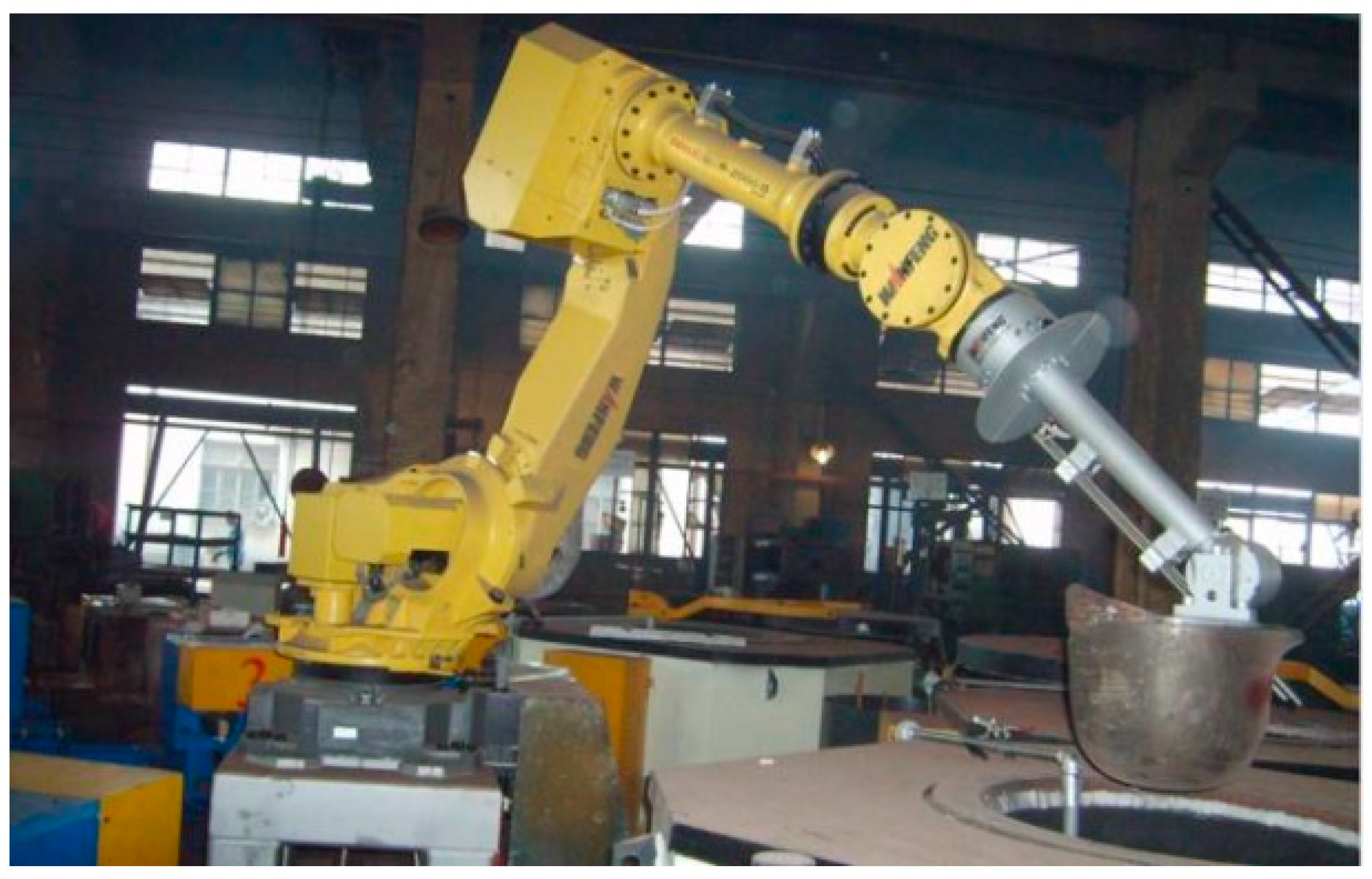
Figure 1. six degrees of freedom casting robot.
Preprints 105265 g001
Figure 2. four degrees of freedom heavy-duty casting robot [2].
Preprints 105265 g002
Figure 3. 3D modeling of the casting robot.
Preprints 105265 g003
Figure 4. Cross-sectional differential analysis diagram.
Preprints 105265 g004
Figure 5. Casting analysis of the first stage of casting of the casting ladle.
Preprints 105265 g005
Figure 6. Two-stage analysis of pouring ladle.
Preprints 105265 g006
Figure 7. Analysis of the third stage of the pouring ladle.
Preprints 105265 g007
Figure 8. Image of time as a function of angle.
Preprints 105265 g008
Figure 9. Image of time as a function of angular velocity.
Preprints 105265 g009
Figure 10. Image of casting drum kinetic function.
Preprints 105265 g010
Figure 11. Plot of time vs. angle as a function of time.
Preprints 105265 g011
Figure 12. Comparison of time as a function of angular velocity.
Preprints 105265 g012
Figure 13. Comparison of time as a function of angular acceleration.
Preprints 105265 g013
Figure 14. Comparison of corrected time as a function of angular acceleration.
Preprints 105265 g014
Figure 15. Comparison of corrected angular velocity function.
Preprints 105265 g015
Figure 16. Comparison of corrected angle functions.
Preprints 105265 g016
Figure 17. Pouring operation test.
Preprints 105265 g017
Table 1. Parameters of Pouring Barrels.
Bottom radius r barrel high Vertical distance from mouth l1 Wide mouthd
12cm 25.5cm 3cm 1.7cm
Table 2. Quantitative casting experiment data table.
Moment/s 5 7 9 11 13 15 17 19
Volume/cm3 0 553.1 567.7 561.6 561.2 561.4 561.4 561.5
Moment/s 21 23 25 27 29 31 33 35
Volume/cm3 565.3 570.3 548.8 561.0 561.8 560.5 562.8 560.4
Disclaimer/Publisher’s Note: The statements, opinions and data contained in all publications are solely those of the individual author(s) and contributor(s) and not of MDPI and/or the editor(s). MDPI and/or the editor(s) disclaim responsibility for any injury to people or property resulting from any ideas, methods, instructions or products referred to in the content.
Copyright: This open access article is published under a Creative Commons CC BY 4.0 license, which permit the free download, distribution, and reuse, provided that the author and preprint are cited in any reuse.
Prerpints.org logo

Preprints.org is a free preprint server supported by MDPI in Basel, Switzerland.

Subscribe

© 2024 MDPI (Basel, Switzerland) unless otherwise stated