Submitted:
31 May 2024
Posted:
03 June 2024
You are already at the latest version
Abstract
Keywords:
1. Introduction
1.1. Medical Significance of EEG Signals Acquisition
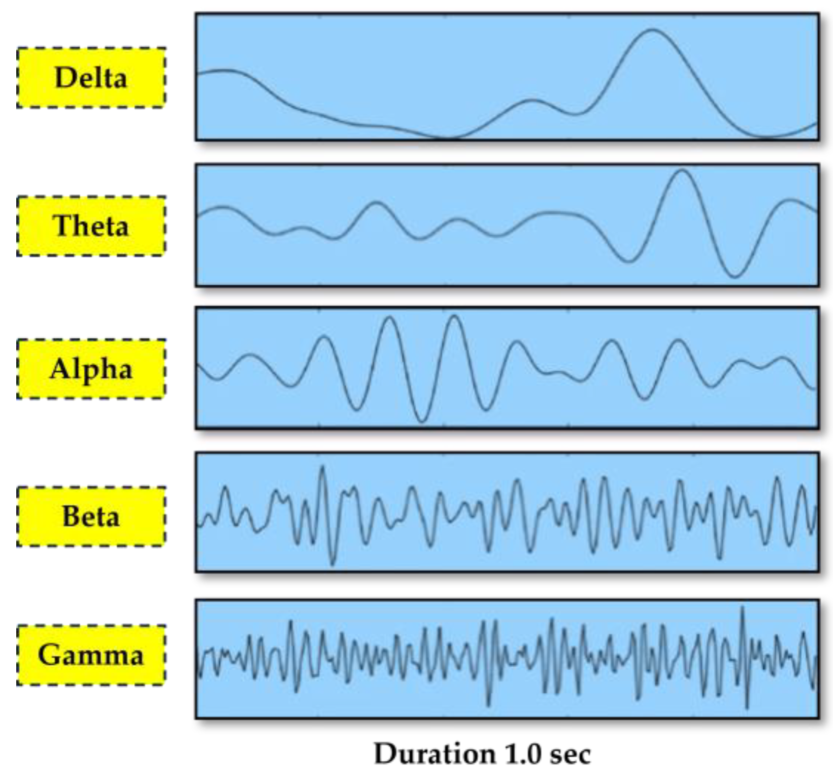
1.2. EEG Signals into Frequency Sub-bands: Comprehensive Categorization
1.3. Noise Interference in EEG Signal Acquisition
1.4. Design Specifications in Medical-Grade and Research-Grade EEG Generic Circuits Design
1.5. Problem Statement and Structure of the Present Study
- Section 1 (Introduction) highlights the medical importance of acquiring an EEG signal and its role in patient monitoring. It also discusses the sub-bands of frequencies into which the EEG signal is classified and introduces the challenges that noise brings in an acquired EEG signal.
- Section 2 (Related Works in EEG Circuit Design Analog Front-End Architectures) discusses design specifications on medical and research-grade EEG circuits. The selected case studies are elaborated with respect to the comparative analysis of various architectures of EEG AFE.
- Section 3 (Materials and Methods: Novel Proposed EEG Analog Front End Circuit System) puts forth a novel methodology for simulating and evaluating the novel EEG AFE circuitry design against practical cases using MATLAB.
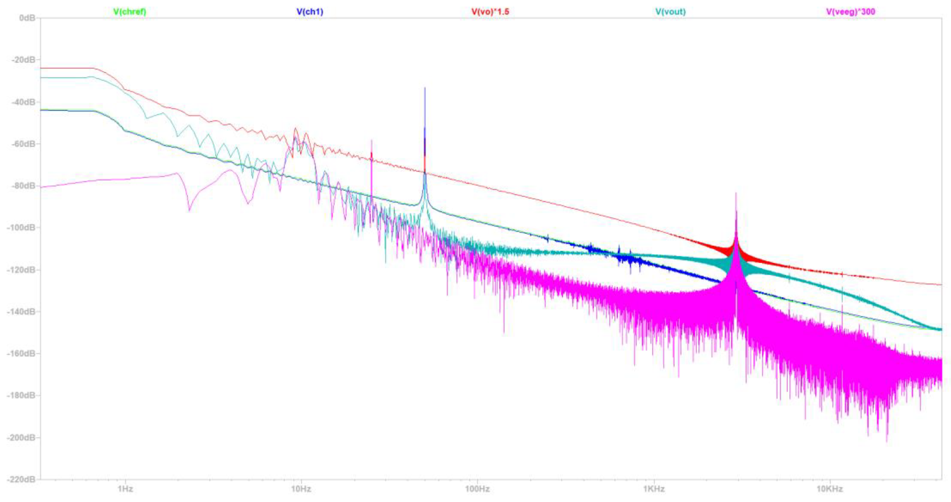
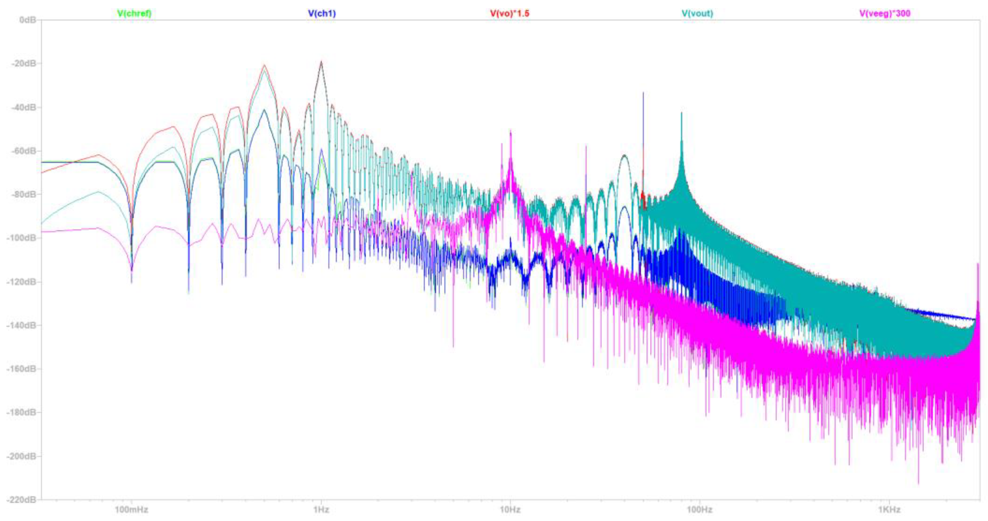
- Section 4 (Simulation and Results: Comprehensive Analysis) is presented with the objective to compare the theoretical values with the simulated values in a real-world scenario for the given circuit design EEG-B3V3S7C1. The circuit's performance is simulated into two of the commonest EEG measurement scenarios: the 50Hz and 60Hz power grid environments that exist outside the shielded lab conditions.
- Section 5 (Discussion) discusses the practical implications, potential limitations, and future perspectives of the proposed EEG circuit design.
- Section 6 (Conclusions) summarizes the entire article.
2. Related Works: EEG Circuit Design Analog Front-End Architectures
2.1. Low-Cost Circuit Design of EEG Analog Front ends: Case ''1''
2.1.1. Description of Topology and Connectivity
2.1.2. Requirements and Specifications in the EEG Circuit: Case ''1''
2.2. Battery-Powered, Low-Noise Amplifier Circuit Design of EEG Analog Front ends: Case ''2'
2.2.1. Description of Topology and Connectivity
2.2.2. Requirements and Specifications in EEG Circuit: Case ''2''
2.3. Double Notch Filter Circuit Design of EEG Analog Front ends: Case ''3''
2.3.1. Description of Topology and Connectivity
2.3.2. Requirements and Specifications in EEG Circuit: Case ''3''
3. Materials and Methods: A Novel Proposed EEG Analog Front End Circuit System
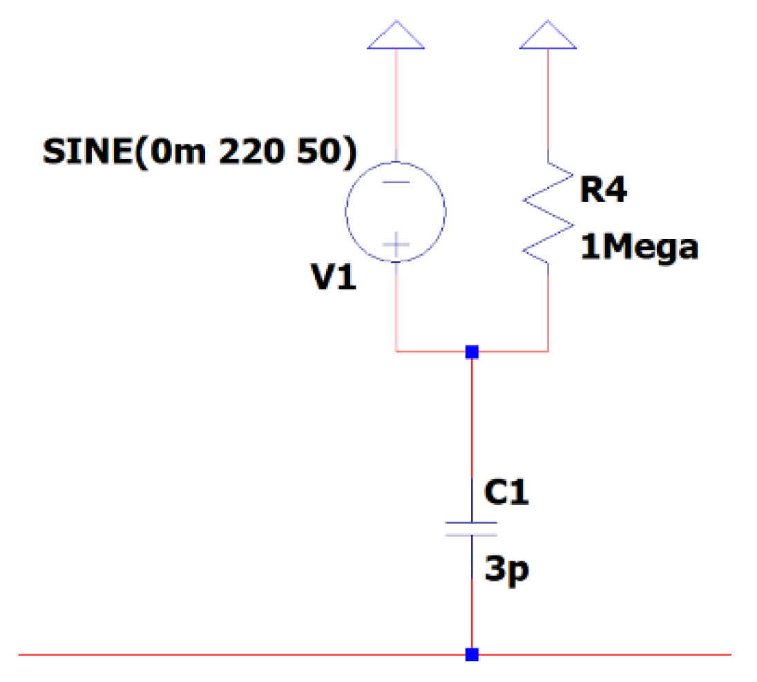
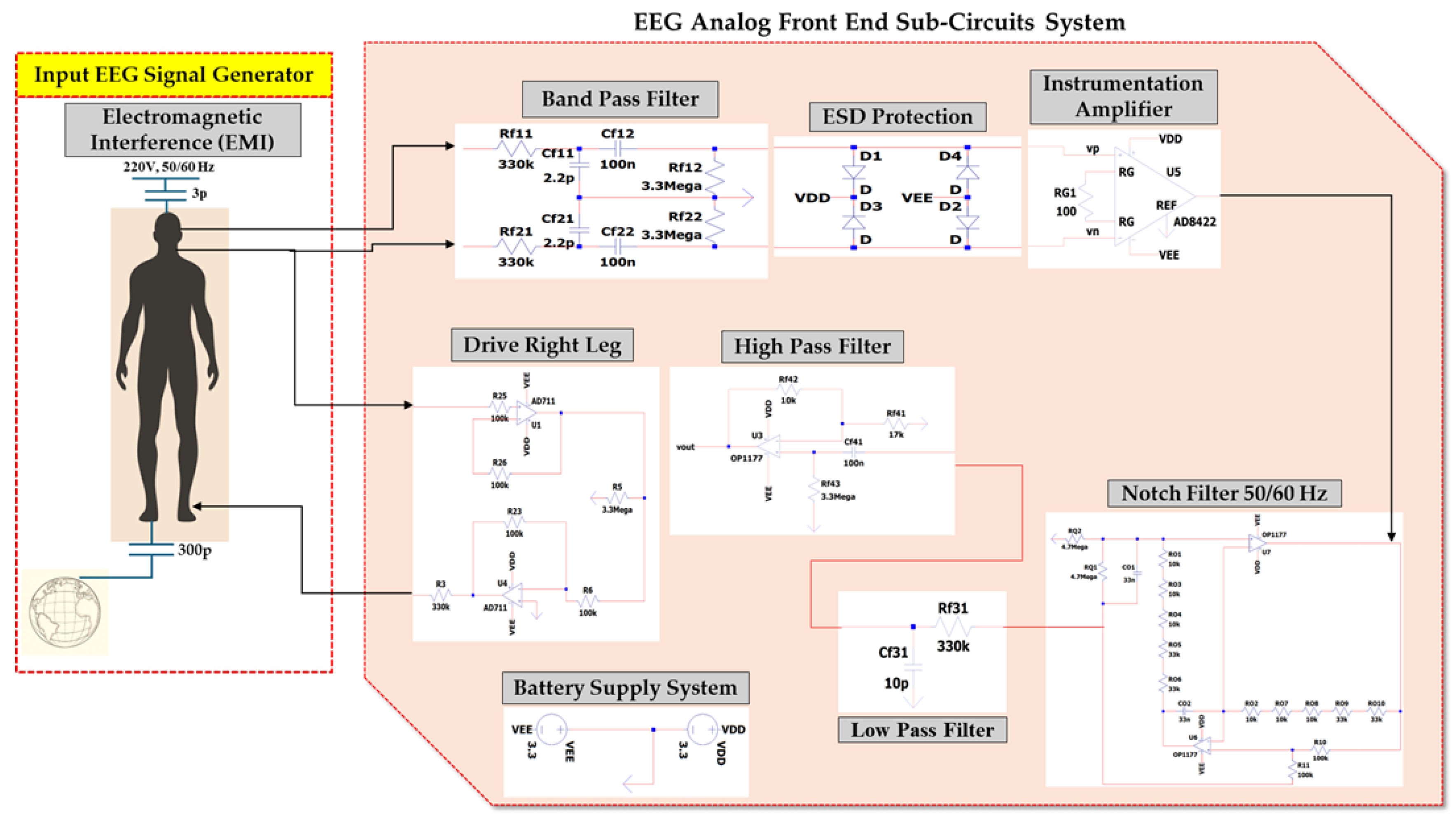
- 3.1: Simulates the EMI noise,
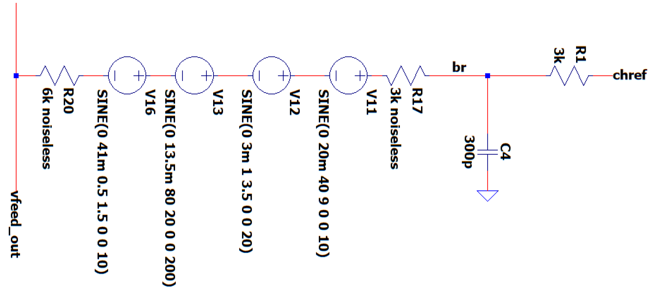
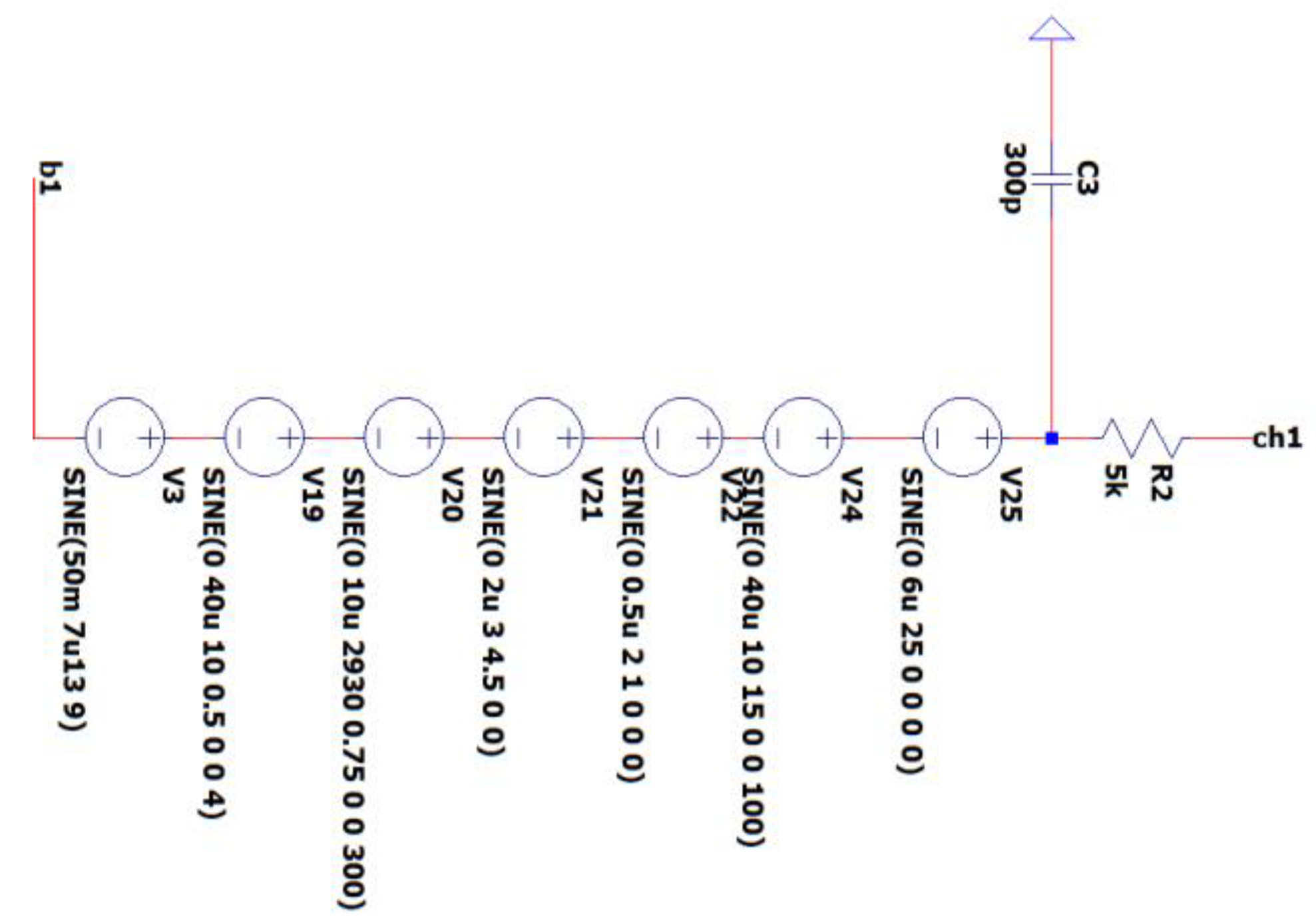
- 3.2: Simulates all types of muscle artifacts (noise stemming from either EMG, EOG, or ECG types of signals),
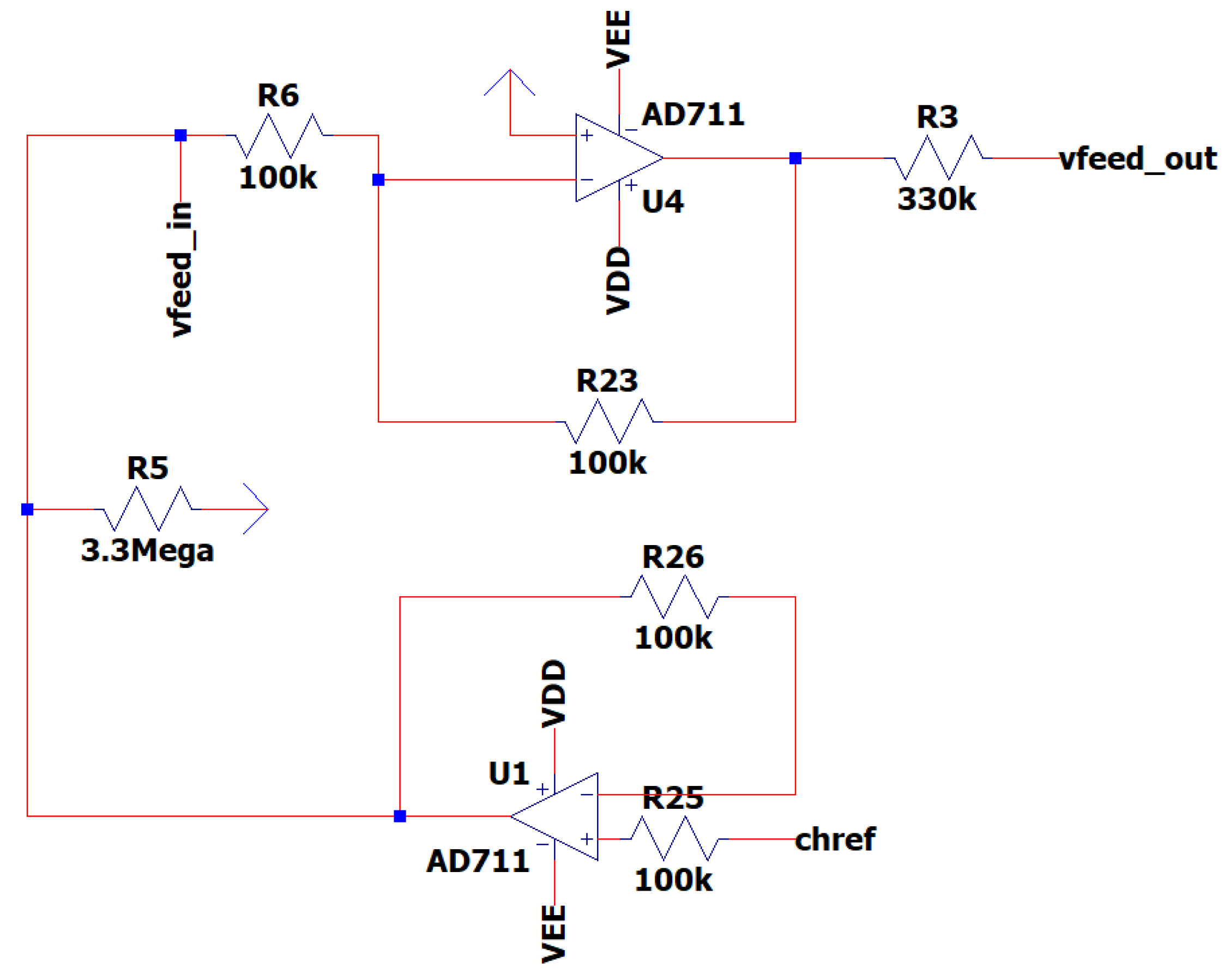
- 3.5: Provides a feedback loop between the circuit and the body that leads to the reduction of the overall noise and the possible sharp changes that may occur in the noise sources.,
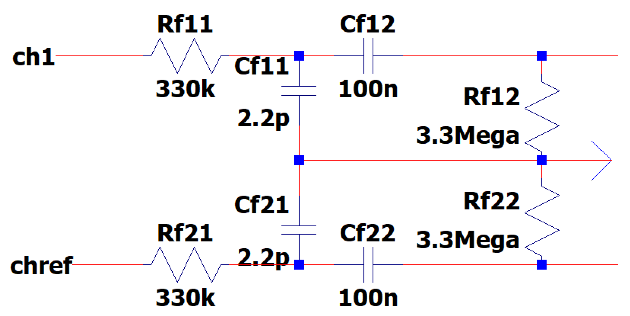
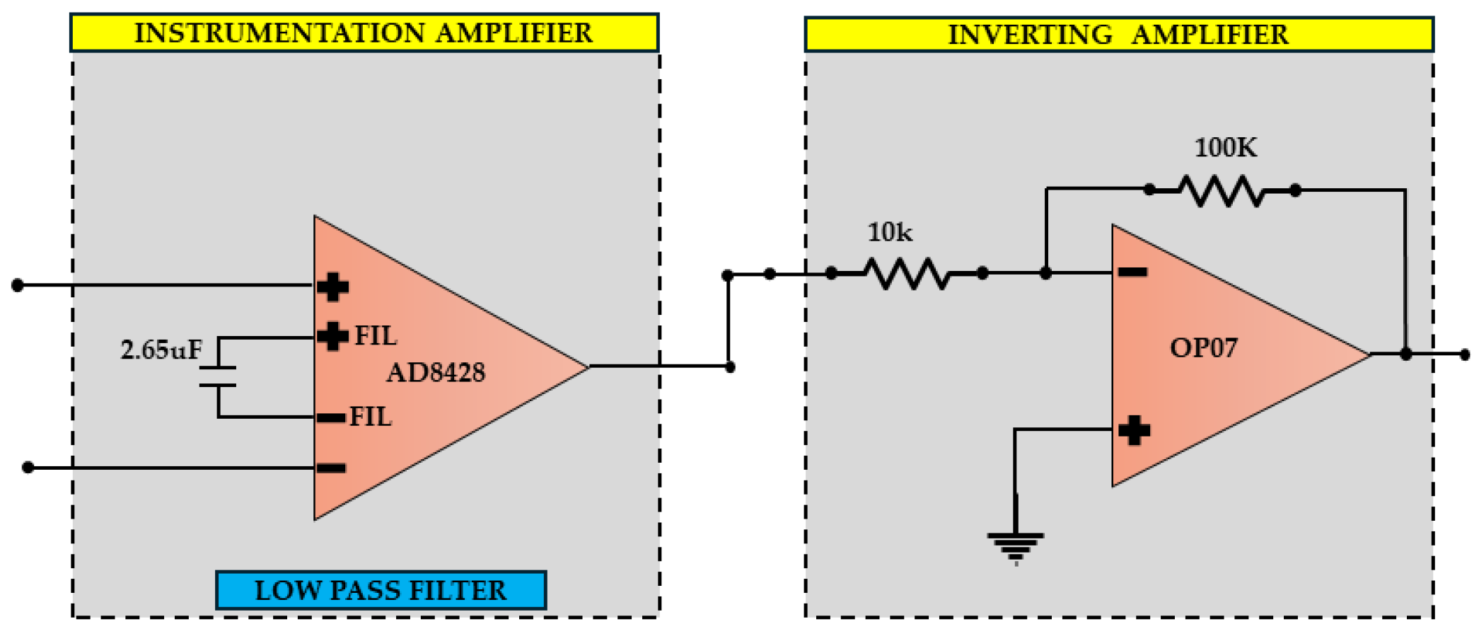
- 3.6: Achieves an initial reduction of dc-offset and low-frequency and high-frequency noises,
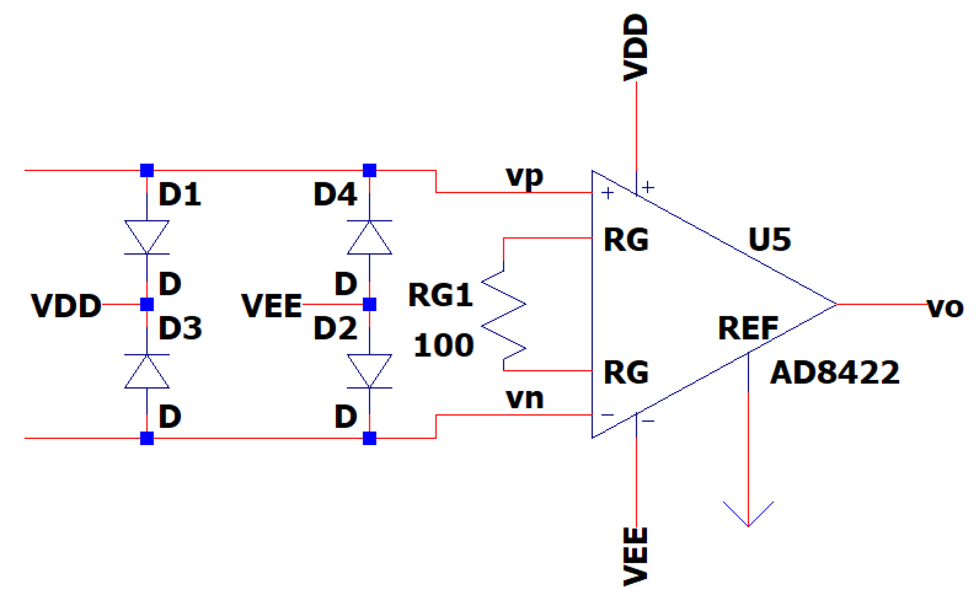
- 3.7: Significantly reduces both EMI and artifacts that are contained in the common mode part of the input signal,
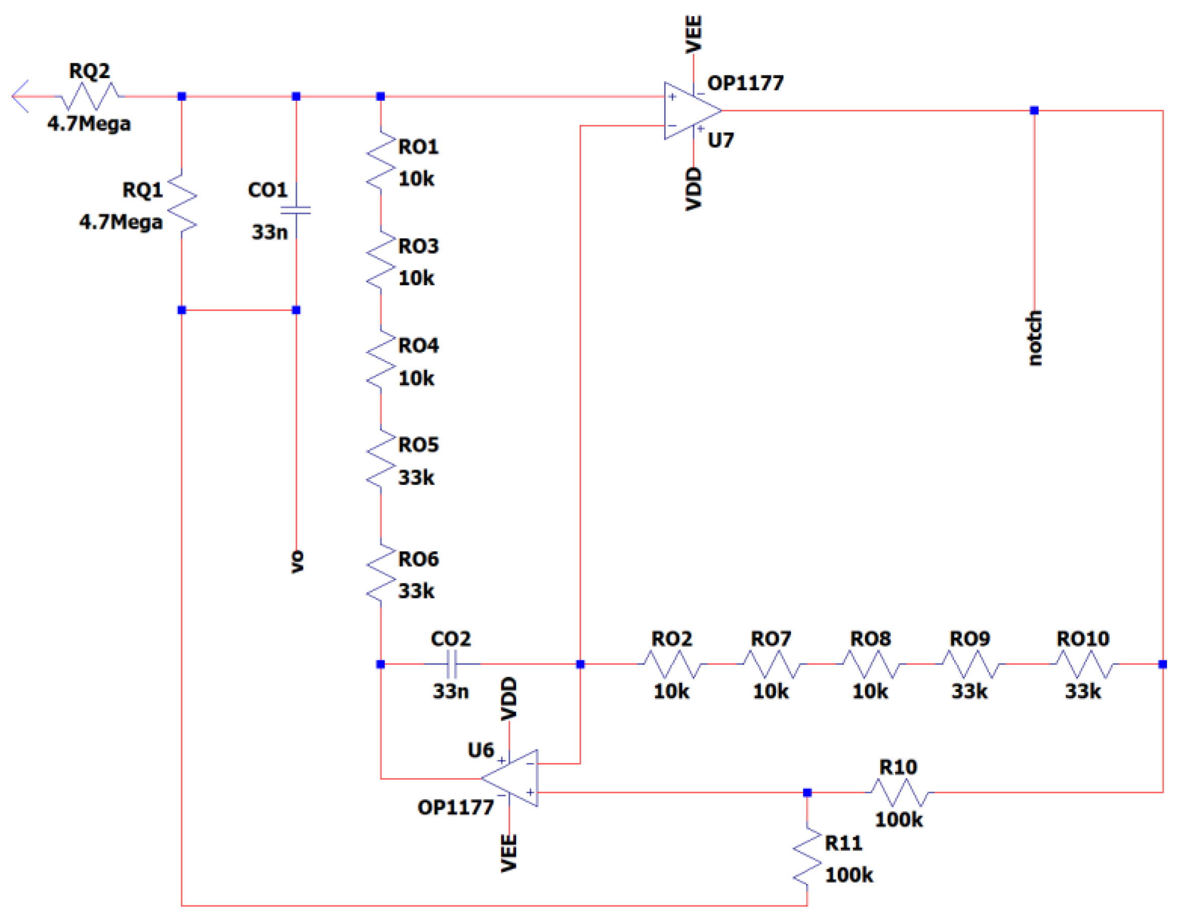
- 3.8: Eliminates the remaining EMI noise from the Main either at 50 Hz or 60 Hz depending on the region specific configuration of the circuit that is being used,
- 3.9: Eliminates the remaining high-frequency noises,
- 3.10: Eliminates the remaining dc-offset and the low-frequency noises.
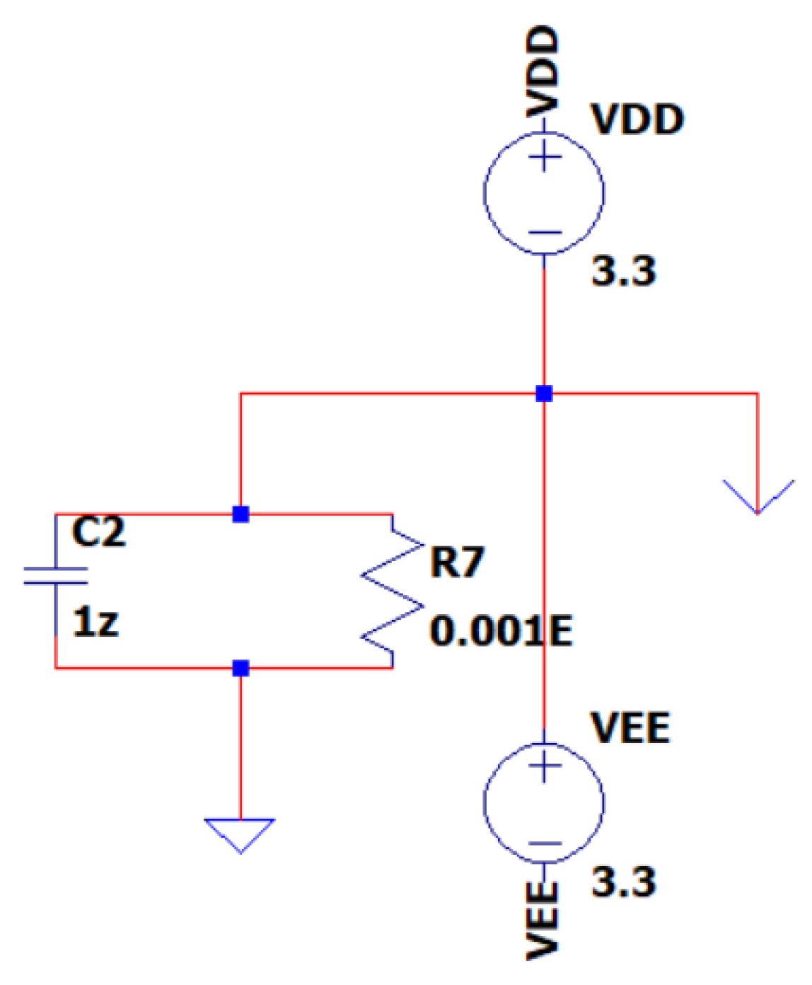
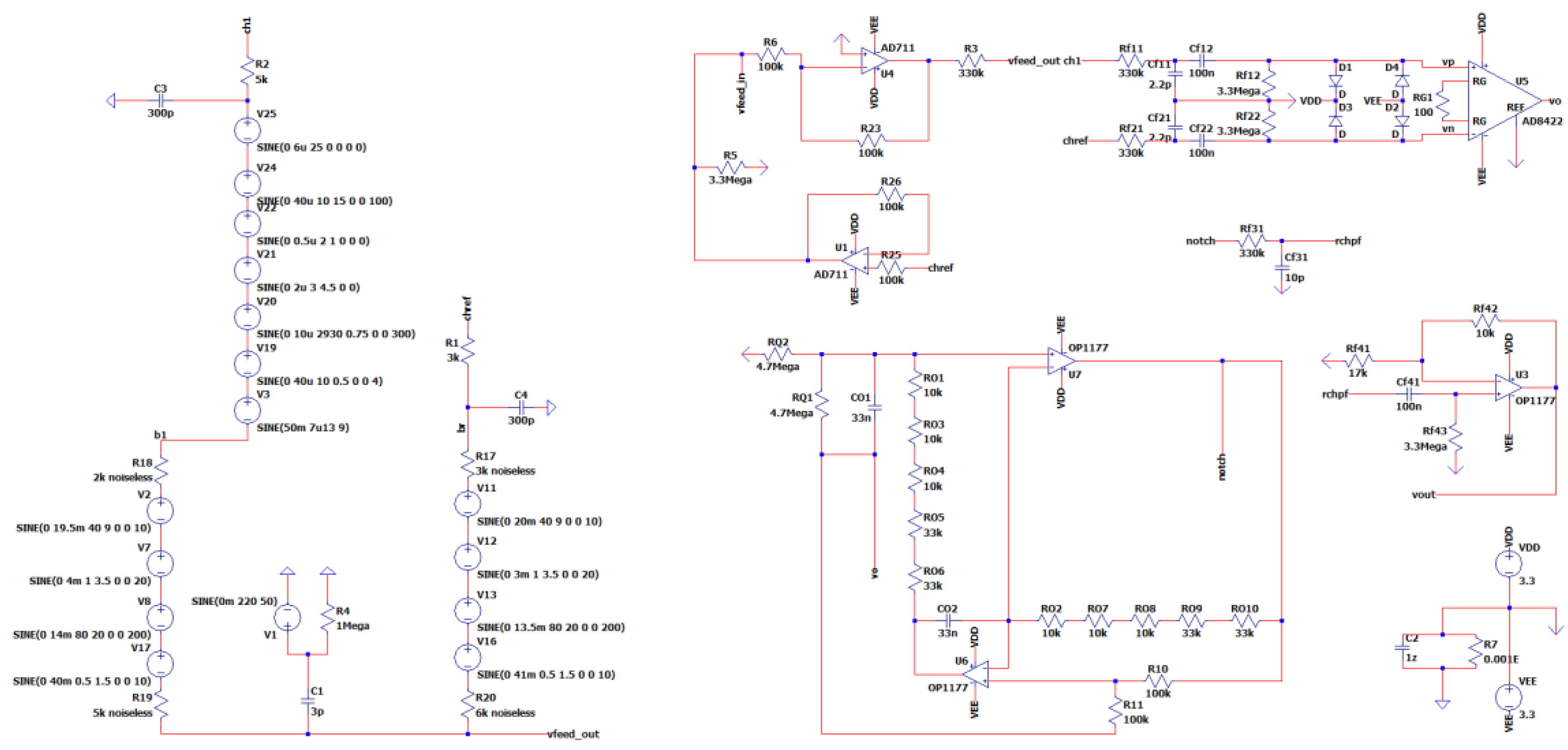
- For detailed figures of each subcircuit (see Figures C.1-C.10), as well as exact calculations of the provided values and equations that govern the subcircuits in cases they are not provided in the subchapters (for space conservation reasons), please see Appendix C.
3.1. EEG Sub-Circuit Modeling the Electromagnetic Interference of Electric Grid with the Human Body
3.2. EEG Sub-Circuit Modeling the Human Body Apart from the Brain and Earth
3.3. EEG Sub-Circuit Modeling the Brain and the Electrode
3.4. EEG Sub-Circuit Modeling the Battery Supply of the System
3.5. EEG Sub-Circuit Modeling the Driven Right Leg (DRL) Circuit
3.6. EEG Sub-Circuit Modeling the First Band-Pass Filter
3.7. EEG Sub-Circuit Modeling the ESD Protection and the Instrumentation Amplifier
3.8. EEG Sub-Circuit Modeling the Fliedge Notch Filter 50Hz or 60Hz
3.9. EEG Sub-Circuit Modeling the Second Low Pass Filter
3.10. EEG Sub-Circuit Modeling the Second High Pass Filter before the Analog to Digital Conversion
3.11. The Overall Novel EEG-B3V3S7C1 Circuit Design
4. Simulation and Results: Comprehensive Analysis
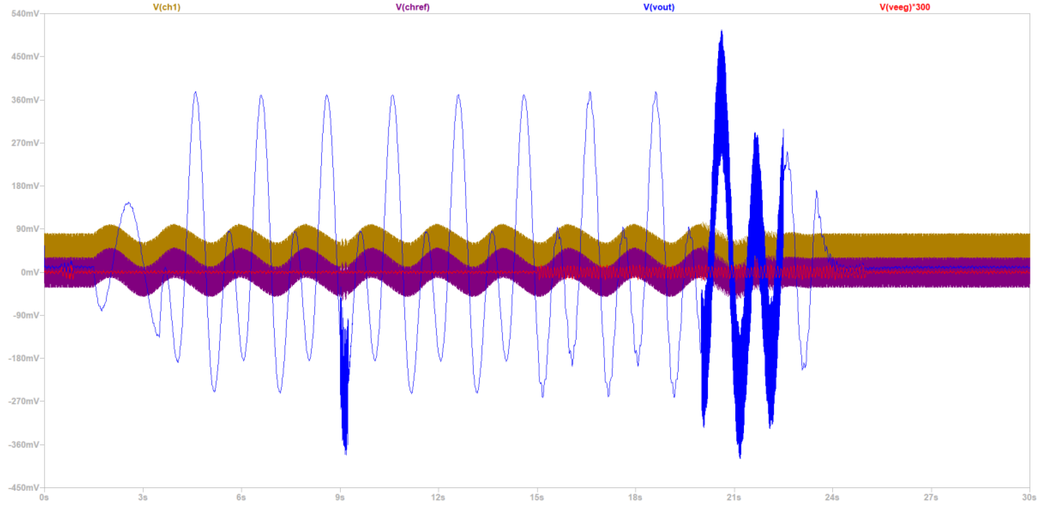
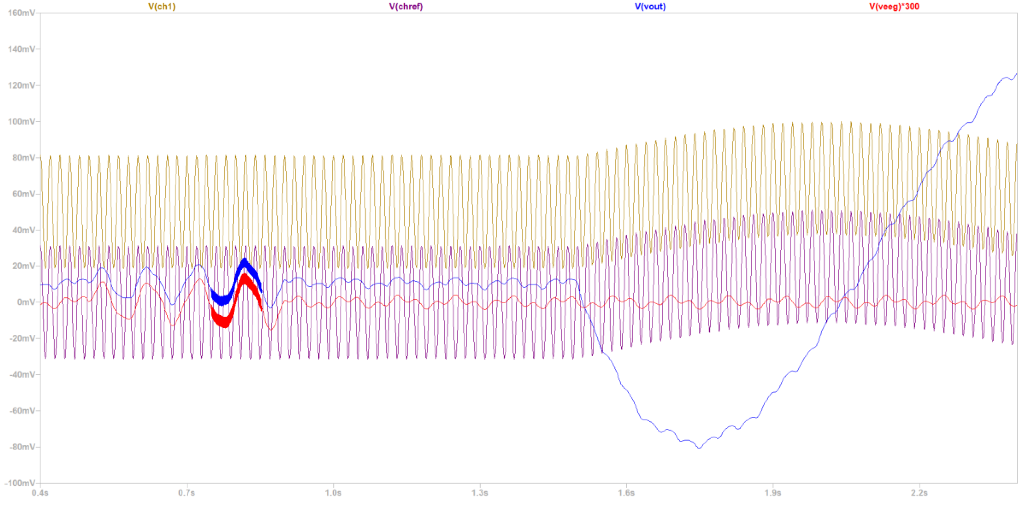
- Time domain to make a qualitative commenting in regard to CMRR, power consumption, gain, and noise level before the first amplification.
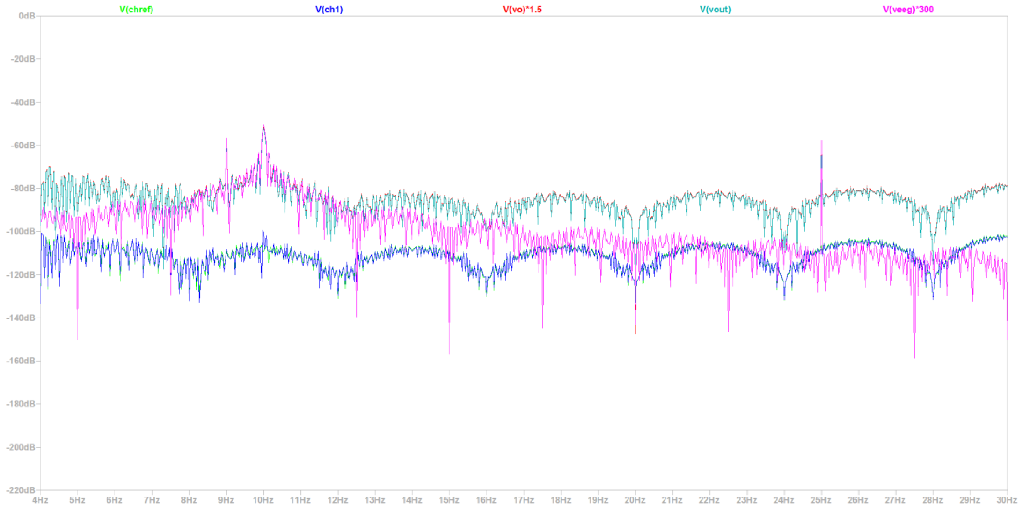
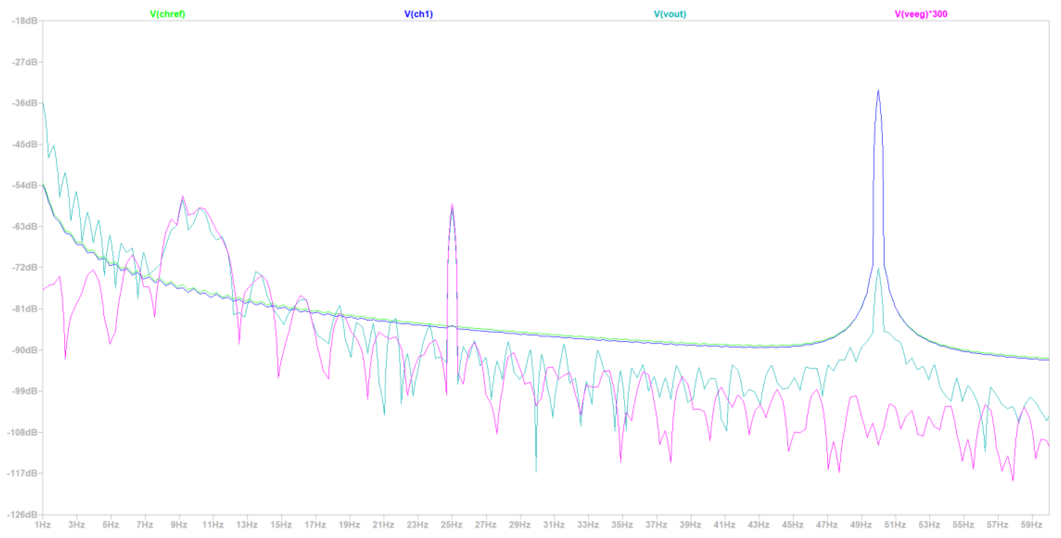
- Fourier frequency spectrum to validate if the information in the alpha, beta and theta wave bands is preserved.
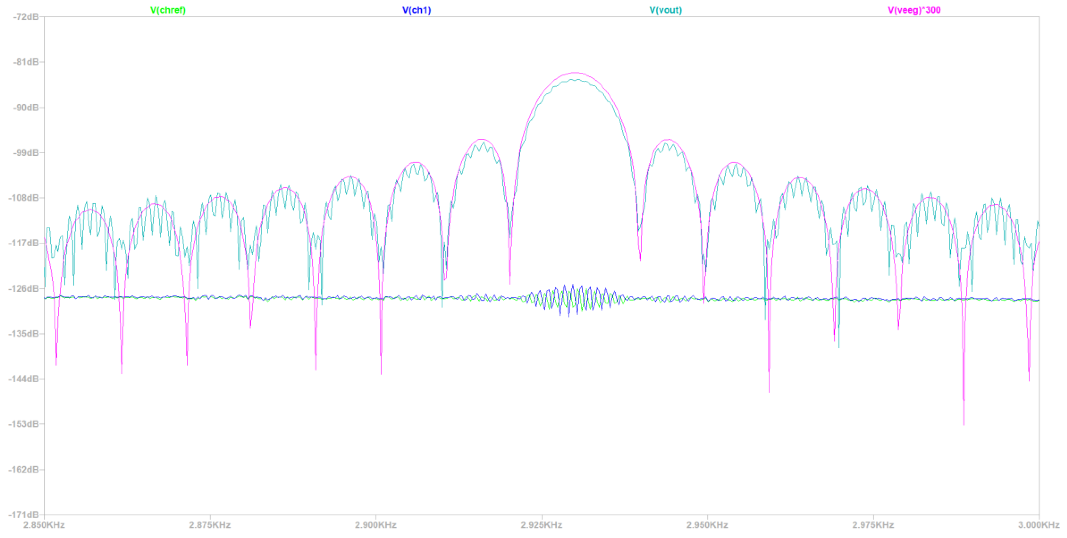
- Fourier frequency spectrum and time domain to validate that the compound muscle movement artifacts are sufficiently suppressed.
4.1. Simulation of Novel EEG-B3V3S7C1 Circuit Design
4.1.1. Simulation in a 50 Hz Electrical Grid Environment
- Simulation at a 50 Hz Electrical Grid Environment in the Time Domain
- Simulation at 50 Hz Electrical Grid Environment at the Fourier’s Spectrum
4.1.2. Simulation in an Environment with an Electrical Grid with Frequency 60 Hz
4.2. Comparative Analysis of the Simulated EEG-B3VS7C2 with the Cases 1, 2, 3
5. Discussion
5.1. Observed Limitations of the Proposed EEG Circuit Design
5.2. Future Perspectives: Possible Updates and Real-World Applications of the Proposed EEG Circuit Design
6. Conclusions
Author Contributions
Funding
Institutional Review Board Statement
Informed Consent Statement
Data Availability Statement
Conflicts of Interest
Appendix A
| Frequency Band | Significance | Key Topics |
|---|---|---|
| Delta (0.5-4 Hz) | Deep Sleep, Unconsciousness | Basics and Beyond, Significance in Sleep and Memory, Methods, and Applications |
| Theta (4-8 Hz) | Creativity, Meditation, Drowsiness | Bridging Consciousness, Thalamic Origins, Practical Insights |
| Alpha (8-13 Hz) | Relaxation, Calmness, Decreased Attention | Indicators of Visual Activation,Enhancing Techniques andBenefits |
| Beta (13-30 Hz) | Active Thinking, Focus, Anxiety | Association with Alertness, Analysis to Application |
| Gamma (30-100 Hz) | Higher Mental Activity,Perception, Consciousness | Cognitive Functions, Exploring High-Frequency Bands |
| Type of Noise | Frequency Range | Source/Characteristics | Impact on EEG Signal | Mitigation Measures |
|---|---|---|---|---|
| Hardware Noise (DC) | 0 Hz (DC) | Originates from wiring and electrical components of the recording system | Values up to a few μV | Use of special gear for noise reduction/isolation |
| Muscle Noise | 0-200 Hz (1-50 Hz most impactful) |
Caused by muscle activity, including minor movements like eye blinking |
Values may exceed 100 mV |
Careful electrode installation, skilled operators for reduction |
| Motion, Breath, Sweat and Cardiac Noise | 0-1.2 Hz | Due to normal physical activities |
Values may reach 10-80 μV |
Proper installation and setup |
| Eye Motion & Electromagnetic Field Noise | 0-16 Hz | Eye motion and intensity of electromagnetic fields | Values between 50-100 μV |
Correct electrode placement, skilled operators |
| Electromagnetic Interference (EMI) & Circuit Noise | 50 Hz (e.g. Greece), 60 Hz (e.g. USA) |
From electrical power lines and nearby electronic devices | Significant distortion possible |
Use of special filters for isolation |
| Category | Subcomponent | Function Description |
|---|---|---|
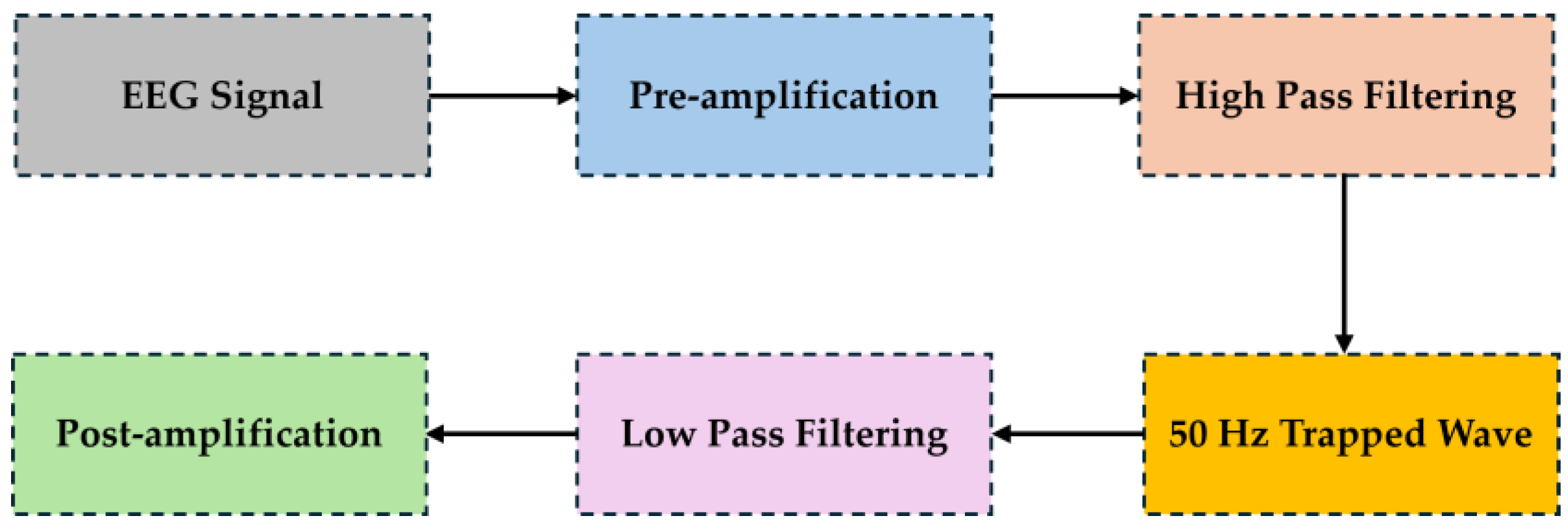
| Filter | Notch Filter | Eliminates power line interference, typically at 50 or 60 Hz. |
| Anti-Aliasing Filter | Prevents aliasing by removing high-frequency components before analog-to-digital conversion. | |
| High Pass Filter | Removes low-frequency components, typically below 0.1 Hz. | |
| Low Pass Filter | Cuts off frequencies higher than a certain threshold to remove high-frequency noise. | |
| Circuit | Chopper Circuit | Reduces low-frequency noise and drift in DC amplifiers by modulating and demodulating the input signal. |
| ESD Protection Circuit | Protects sensitive EEG electronics from static electricity. | |
| Amplifier | Operational Amplifier (Op-Amp) |
Amplifies the EEG signal with high gain and stability. |
| Programmable Gain Amplifier | Allows for adjustment of the amplification level of the EEG signal. |
|
| Instrumentation Amplifier with Integrated Filter |
Provides high input impedance, and low noise, and includes integrated filters for signal conditioning. | |
| Other Subcomponents | Analog Mux (Multiplexer) | Selects one of several input signals and forwards it into a single line in multi-channel EEG systems. |
| Analog to Digital Converter (ADC) | Converts the analog EEG signal into a digital format for processing and analysis. |
|
| Drive Right Leg Circuit | Reduces common-mode interference in biopotential amplifiers. |
| Aspect | Medical-Grade EEG | Research-Grade EEG |
|---|---|---|
| Accuracy and Resolution | Higher accuracy and resolution for diagnostic purposes | Slightly lower resolution, suitable for studying brain patterns |
| Number of Electrodes | Higher number, standardized layouts (e.g., 10-20 system) |
Fewer electrodes, focusing on specific brain regions |
| Signal Quality and Noise Reduction | Advanced noise reduction for highly accurate readings | Noise reduction present, but may prioritize flexibility in analysis |
| Regulatory Compliance and Certification | Must meet strict regulatory standards (e.g., FDA approval) |
Not subjected to the same level of regulatory scrutiny |
| Durability and Robustness | Designed for frequent and sustained use, more durable | May not be as durable, focuses on flexibility for research |
Appendix B
B.1. Supplementary information for Case “1”
B.1.1 Comparative Evaluation with EEG Generic Circuit Design
B.1.2. Usage-Centric Justification for Design Differentiation: Case ''1''
B.1.3. Simulation - Experimental Results: Case ''1''
B.2. Supplementary information for Case “2”
B.2.1. Comparative Evaluation with EEG Generic Circuit Design
B.2.2. Usage-Centric Justification for Design Differentiation: Case ''2''
B.2.3. Simulation - Experimental Results: Case ''2''
B.3. Supplementary Information for Case “3”
B.3.1. Comparative Evaluation with EEG Generic Circuit Design
B.3.2. Usage-Centric Justification for Design Differentiation: Case ''3''
B.3.3. Simulation - Experimental Results: Case ''3''
B.4. Supplementary Information for Four other Circuits of Related Works
| Feature | Description |
|---|---|
| Common Mode Rejection Ratio (CMRR) | The AD620 instrumentation amplifier used in the design has a high CMRR of 110 dB, crucial for minimizing noise and interference in EEG signals. |
| Signal Bandwidth/Frequency Range | Targets neonatal EEG signals, predominantly delta waves, with frequencies from 0.5 to 2 Hz, 100μV amplitude. |
| Gain | Total gain of 17776 V/V. Individual stage gains:
|
| Filter Characteristics | High pass and low pass filters with cutoff frequencies of 0.16 Hz and 50 Hz, respectively to remove DC offset and power line interference |
| Feature | Description |
|---|---|
| Common Mode Rejection Ratio (CMRR) | High CMRR suitable for EEG applications |
| Signal Bandwidth | 0.5 to 40 Hz |
| Variable Gain | Between 100 and 7000 |
| Power Consumption | Low |
| Portability | Designed for portability |
| Components | Uses commercially available components |
| Cost | Cost-effective |
| Signal Quality Metrics | Detailed metrics not directly provided |
| Feature | Description |
|---|---|
| Common Mode Rejection Ratio (CMRR) | 102 dB, effective in reducing noise and interference from common-mode signal |
| Amplifier Gain | Variable, with options for 5000, 10000, 20000,or 30000 V/V |
| Pass-Band Frequency | Ranges from 0.12Hz to 35.4Hz, accommodating the typical frequency range of EEG signals |
| Input Impedance | 113MΩ, ensuring that the circuit does not significantly load the signal source, preserving signal integrity |
| Feature | Description |
|---|---|
| Common Mode Rejection Ratio (CMRR) | 100 dB for gains ≥ 100, aiming for effective common-mode noise rejection |
| Amplifier Gain | G≥100V/V |
| Modified High-Q Factor Active Twin-T Notch Filter |
60 Hz and a rejection level of -38 dB. |
| PCB Size | Less than 5.5 cm2 |
Appendix C
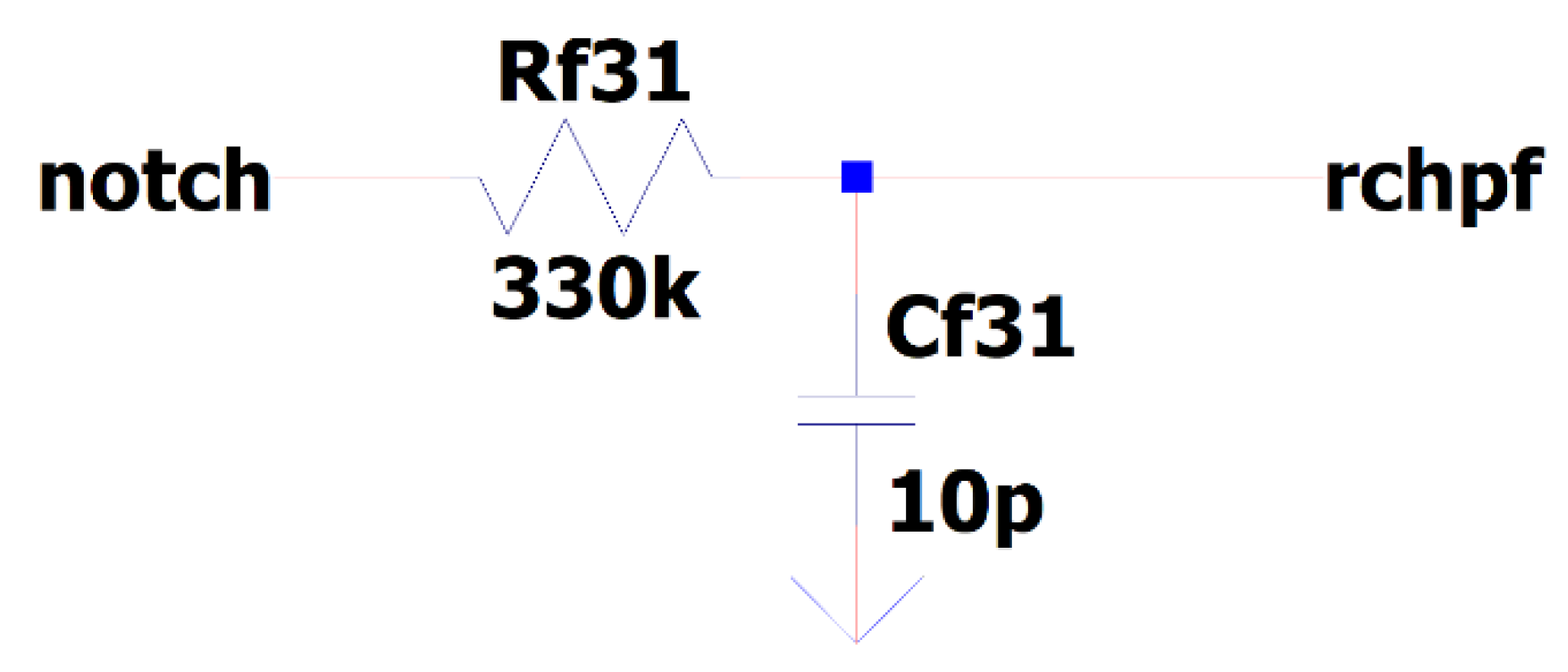
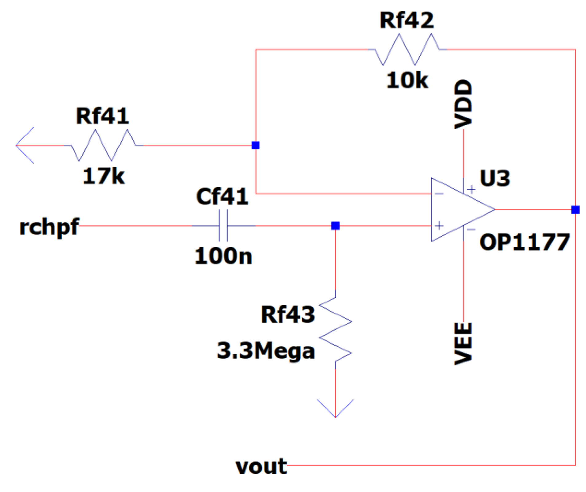
- kB is the Boltzmann's constant,
- T is absolute temperature in Kelvin in our case at room temperature (usually 25 Co) and
- R is the real part of the band-pass filter’s impedance.
References
- . [CrossRef]
- Chaudhary, U.; Birbaumer, N.; Ramos-Murguialday, A. Brain–computer interfaces for communication and rehabilitation. Nature Reviews Neurology 2016, 12, 513–525. [Google Scholar] [CrossRef] [PubMed]
- Sanei, S.; Chambers, J.A. Fundamentals of EEG Signal Processing. EEG Signal Processing 2007, 35–12. [Google Scholar] [CrossRef]
- Tatum, W.O. Ambulatory EEG. In Handbook of EEG Interpretation; Springer Publishing Company: location, 2021. [Google Scholar] [CrossRef]
- Benbadis, S.R.; Beniczky, S.; Bertram, E.; MacIver, S.; Moshé, S.L. The role of EEG in patients with suspected epilepsy. Epileptic Disorders 2020, 22, 143–155. [Google Scholar] [CrossRef] [PubMed]
- Rubiños, C.; Godoy, D.A. Electroencephalographic monitoring in the critically ill patient: What useful information can it contribute? Medicina Intensiva (English Edition) 2020, 44, 301–309. [Google Scholar] [CrossRef]
- Michel, C.M.; Murray, M.M. Towards the utilization of EEG as a brain imaging tool. NeuroImage 2012, 61, 371–385. [Google Scholar] [CrossRef] [PubMed]
- Aboalayon, K.; Faezipour, M.; Almuhammadi, W.; Moslehpour, S. Sleep Stage Classification Using EEG Signal Analysis: A Comprehensive Survey and New Investigation. Entropy 2016, 18, 272. [Google Scholar] [CrossRef]
- Diykh, M.; Li, Y.; Wen, P. EEG Sleep Stages Classification Based on Time Domain Features and Structural Graph Similarity. IEEE Transactions on Neural Systems and Rehabilitation Engineering 2016, 24, 1159–1168. [Google Scholar] [CrossRef]
- Asadzadeh, S.; Yousefi Rezaii, T.; Beheshti, S.; Delpak, A.; Meshgini, S. A systematic review of EEG source localization techniques and their applications on diagnosis of brain abnormalities. Journal of Neuroscience Methods 2020, 339, 108740. [Google Scholar] [CrossRef]
- Dhar, P.; Garg, V.K. Brain-Related Diseases and Role of Electroencephalography (EEG) in Diagnosing Brain Disorders; Lecture Notes in Networks and Systems; Springer: Singapore, 2020; pp. 317–326. [Google Scholar] [CrossRef]
- Ullah, H.; Mahmud, S.; Chowdhury, R.H. Identification of Brain disorders by Sub-band Decomposition of EEG signals and Measurement of Signal to Noise Ratio. Indonesian Journal of Electrical Engineering and Computer Science 2016, 4, 568. [Google Scholar] [CrossRef]
- Iscan, Z.; Dokur, Z.; Demiralp, T. Classification of electroencephalogram signals with combined time and frequency features. Expert Systems with Applications 2011, 38, 10499–10505. [Google Scholar] [CrossRef]
- Siuly, S.; Li, Y.; Zhang, Y. Electroencephalogram (EEG) and Its Background. EEG Signal Analysis and Classification 2016, 3–21. [Google Scholar] [CrossRef] [PubMed]
- Puce, A.; Hämäläinen, M. A Review of Issues Related to Data Acquisition and Analysis in EEG/MEG Studies. Brain Sciences 2017, 7, 58. [Google Scholar] [CrossRef] [PubMed]
- Mumtaz, W.; Rasheed, S.; Irfan, A. Review of challenges associated with the EEG artifact removal methods. Biomedical Signal Processing and Control 2021, 68, 102741. [Google Scholar] [CrossRef]
- Usakli, A.B. Improvement of EEG Signal Acquisition: An Electrical Aspect for State of the Art of Front End. Computational Intelligence and Neuroscience 2010, 1–7. [Google Scholar] [CrossRef] [PubMed]
- Chen, X.; Xu, X.; Liu, A.; Lee, S.; Chen, X.; Zhang, X.; McKeown, M.J.; Wang, Z.J. Removal of Muscle Artifacts From the EEG: A Review and Recommendations. IEEE Sensors Journal 2019, 19, 5353–5368. [Google Scholar] [CrossRef]
- Sanei, S. Book: Adaptive Processing of Brain Signals; Wiley: location, 2013; ISBN 9781118622162. [Google Scholar] [CrossRef]
- Lebedev, M.A.; Nicolelis, M.A.L. Brain-Machine Interfaces: From Basic Science to Neuroprostheses and Neurorehabilitation. Physiological Reviews 2017, 97, 767–837. [Google Scholar] [CrossRef] [PubMed]
- Elsayed, N.; Saad, Z.; Bayoumi, M. Brain Computer Interface: EEG Signal Preprocessing Issues and Solutions. International Journal of Computer Applications 2017, 169, 12–16. [Google Scholar] [CrossRef]
- Alkhorshid, D.R.; Molaeezadeh, S.F.; Alkhorshid, M.R. Analysis: Electroencephalography Acquisition System: Analog Design. Biomedical Instrumentation & Technology 2020, 54, 346–351. [Google Scholar] [CrossRef] [PubMed]
- Cohen, M.X. Where Does EEG Come From and What Does It Mean? Trends in Neurosciences 2017, 40, 208–218. [Google Scholar] [CrossRef]
- Tankisi, H.; Burke, D.; Cui, L.; de Carvalho, M.; Kuwabara, S.; Nandedkar, S.D.; Rutkove, S.; Stå, *!!! REPLACE !!!*; lberg, E.; van Putten, M.J.A.M.; Fuglsang-Frederiksen, A. Standards of instrumentation of EMG. Clinical Neurophysiology 2020, 131, 243–258. [Google Scholar] [CrossRef]
- Vanhatalo, S.; Voipio, J.; Kaila, K. Full-band EEG (FbEEG): an emerging standard in electroencephalography. Clinical Neurophysiology 2005, 116, 1–8. [Google Scholar] [CrossRef] [PubMed]
- Hari, R.; Parkkonen, L.; Nangini, C. The brain in time: insights from neuromagnetic recordings. Annals of the New York Academy of Sciences 2010, 1191, 89–109. [Google Scholar] [CrossRef] [PubMed]
- Sullivan, T.J.; Deiss, S.R.; Cauwenberghs, G. A Low-Noise, Non-Contact EEG/ECG Sensor. In Proceeding of the IEEE Biomedical Circuits and Systems Conference, Nov. 2007. [CrossRef]
- Scheer, H.J.; Sander, T.; Trahms, L. The influence of amplifier, interface and biological noise on signal quality in high-resolution EEG recordings. Physiological Measurement 2005, 27, 109–117. [Google Scholar] [CrossRef] [PubMed]
- Jobert, M.; Wilson, F.J.; Ruigt, G.S.F.; Brunovsky, M.; Prichep, L.S.; Drinkenburg, W.H.I.M. Guidelines for the Recording and Evaluation of Pharmaco-EEG Data in Man: The International Pharmaco-EEG Society (IPEG). Neuropsychobiology 2012, 66, 201–220. [Google Scholar] [CrossRef] [PubMed]
- Wasade, V.S.; Spanaki, M.V. Understanding Epilepsy; Cambridge University Press: location, 2019. [Google Scholar] [CrossRef]
- Usakli, A.B. Improvement of EEG Signal Acquisition: An Electrical Aspect for State of the Art of Front End. Computational Intelligence and Neuroscience 2010, 1–7. [Google Scholar] [CrossRef] [PubMed]
- Gardella, P.J.; Baez, E.; Cesaretti, J.M. Design of ESD protections for ECG applications. In Proceeding of the Conference on Electronics (CAE), Argentine, Feb 2020. [CrossRef]
- Kuo, K.-C.; Chen, C.-T.; Liao, H.-Y. An Area Efficient Analog Front-End for Sensing EEG Signals with MOS Capacitors in 90nm Process. In Proceeding of the International Conference on Consumer Electronics - Taiwan (ICCE-Taiwan) 2023. [CrossRef]
- Cornelio, Z.U.; Resurreccion, P.; Leon, M.T. de, Rosales; M.; Hizon, J.R. An EEG Analog Front-End Unit for Wearable Applications Implemented in 28nm FD-SOI. In Proceeding of the 20th International SoC Design Conference (ISOCC) 2023. [CrossRef]
- Le, D.H.; Pham, T.-H.; Pham, C.-K. Design of a Configurable 4-Channel Analog Front-End for EEG Signal Acquisition on 180nm CMOS Process. REV Journal on Electronics and Communications 2023. [Google Scholar] [CrossRef]
- Pham, T.-H.; Huynh, H.-A.; Pham, C.-K.; Le, D.-H. Design of a Configurable Low-Noise 1-Channel Analog Front-End for EEG Signal Recording on 180nm CMOS Process. In Proceeding of the International Conference on Advanced Technologies for Communications (ATC) 2023. [CrossRef]
- Li, X.; Ren, S. , Li, X.; Zhao, T.; Deng, X.; Zheng, W. An LFP/AP Mode Reconfigurable Analog Front-End Combining an Electrical EEEG-iEEG Model for the Closed-Loop VNS. IEEE Transactions on Biomedical Circuits and Systems 2024, 18, 408–422. [Google Scholar] [CrossRef]
- Hu, H.-Y.; Wang, L.-H.; Kuo, I.-C.; Wang, M.-H.; Wang, S.-F.; Huang, P.-C. A Multi-Channel EEG Acquisition Device Based on BT Microcontroller. In Proceeding of the International Conference on Consumer Electronics - Taiwan (ICCE-Taiwan) 2023. [CrossRef]
- Han, Y.; Zhao, L.; Stephany, R.G.; Hsieh, J.-C.; Wang, H.; Jia, Y. A Scattered Wireless EEG Recording System. In Proceeding of the IEEE Biomedical Circuits and Systems Conference (BioCAS) 2023. [CrossRef]
- Chen, W. Multi-channel EEG signal acquisition system based on nRF52832. In Proceeding of the 5th International Conference on Communications, Information System and Computer Engineering (CISCE) 2023. [CrossRef]
- Liu, L.; Xu, J.; Yin, J.; Liao, X.; Tian, Y. (). A Low-Power and Constant-Bandwidth Analog Front End Based on Current-Reused DDA for Multibiosignal Acquisition. IEEE Sensors Journal 2023, 23, 24711–24720. [Google Scholar] [CrossRef]
- Ge, T.; Li, P.; Duan, Q.; Yu, G. low-noise, high-precision chopper instrument amplifier for EEG signal amplification. In Proceeding of the 5th International Conference on Circuits and Systems (ICCS) 2023. 2023. [CrossRef]
- Kumar, S.C.P.; Chandrasekar, A.; Nagaraj, A.; Gupta, P.; Sekhar, S. Design of an ElectroEncephaloGram (EEG) amplification circuit for neonates. In Proceeding of the International Conference on Communication and Signal Processing (ICCSP), Apr. 2016. [CrossRef]
- Whitchurch, A.K.; Abraham, J.K.; Lonkar, M.A.; Varadan, V.K. Design of a Compact Amplifier and Signal Conditioning Module for Wireless EEG Monitoring. In Proceeding of the IEEE Region 5 Technical Conference, Apr. 2007. [CrossRef]
- Zhang, X.; Zhang, Z. Design on Sampling Circuit of EEG Signal Based on AT89C2051 Single-Chip. In Proceeding of the Fourth International Conference on Innovative Computing, Information and Control (ICICIC), Dec. 2009. [CrossRef]
- Salahuddin Morsalin, S.M.; Lai, S.-C. Front-end circuit design for electroencephalography (EEG) signal. In Proceeding of the 2nd International Conference on Computing, Analytics and Networks (ICAN), Indo – Taiwan, Feb 2020. [CrossRef]
- Xu, X.; Wang, P. Low-Cost Circuit Design for EEG Signal Amplification and Extraction. In Proceeding of the IEEE Asia-Pacific Conference on Image Processing, Electronics and Computers (IPEC), Apr. 20212021. [CrossRef]
- Choudhary, S.K.; Bera, T.K. Designing of Battery-Based Low Noise Electroencephalography (EEG) Amplifier for Brain Signal Monitoring: A Simulation Study. In Proceeding of the IEEE 6th International Conference on Condition Assessment Tech-niques in Electrical Systems (CATCON), 422-426, Durgapur, India, 2022). [CrossRef]
- Analog Devices, Inc. AD8428: High Gain, High Voltage Instrumentation Amplifier. Data Sheet. Available online: https://www.analog.com/media/en/technical-documentation/data-sheets/ad8428.pdf (accessed on 10 Februaty 2024).
- Yuge, Sun.; Ning, Ye.; Feng, Pan. A novel design of EEG signal amplifier. In Proceeding of the 24th Chinese Control and Decision Conference (CCDC), May 2012. [CrossRef]
- Tsavdaridis, G.; Papaodysseus, C.; Karadimas, N.V.; Papazafeiropoulos, G.; Delis, A. Methodologies and Handling Techniques of Large-Scale Information in Decision Support Systems for Complex Missions. Applied Sciences 2024, 14, 1995. [Google Scholar] [CrossRef]
- Tsavdaridis, G. Thesis: Adjustable and Adaptable Systems for Crisis Management Support, Monitoring, and Control of Operational Processes. School of Electrical and Computer Engineering, National Technical University of Athens, March 2024 https://www.didaktorika.gr/eadd/handle/10442/56130. 20 March.
- Jobert, M.; Wilson, F.J.; Ruigt, G.S.F.; Brunovsky, M.; Prichep, L.S.; Drinkenburg, W.H.I.M. Guidelines for the Recording and Evaluation of Pharmaco-EEG Data in Man: The International Pharmaco-EEG Society (IPEG). Neuropsychobiology 2012, 66, 201–220. [Google Scholar] [CrossRef] [PubMed]
- Alizadeh-Taheri, B.; Smith, R.L.; Knight, R.T. An Active, Microfabricated, Scalp Electrode-array For EEG Recording. In Proceeding of the International Solid-State Sensors and Actuators Conference - TRANSDUCERS ’95. [CrossRef]
- Zhang, L.; Guo, X.; Wu, X.; Zhou, B. Low-cost circuit design of EEG signal acquisition for the brain-computer interface system. In Proceeding of the 6th International Conference on Biomedical Engineering and Informatics, Dec. 2013. [CrossRef]
- Analog Devices, Inc. AD8422: 1.8 nV/√Hz, Rail-to-Rail, Low Power Instrumentation Amplifier. Data Sheet. Available online: https://www.analog.com/media/en/technical-documentation/data-sheets/ad8422.pdf (accessed on 10 February 2024).
- Zumbahlen, H. Analog Filters. Linear Circuit Design Handbook; Zumbahlen, H., Ed.; Newnes: Burlington, 2008; pp. 581–679. [Google Scholar] [CrossRef]
- Wang, J.; Tang, L.; E Bronlund, J. Surface EMG Signal Amplification and Filtering. International Journal of Computer Applications 2013, 82, 15–22. [Google Scholar] [CrossRef]
- Hsueh, J.-J.; Chen, T.-S.; Chen, J.-J. , & Shaw, F.-Z. Neurofeedback training of EEG alpha rhythm enhances episodic and working memory. Human Brain Mapping 2016, 37, 2662–2675. [Google Scholar] [CrossRef]
- Texas Instruments, INA333 Low-Power, Precision Instrumentation Amplifier. Available online: https://www.ti.com/lit/ds/symlink/ina333.pdf (accessed on 12 February 2024).

| Common Mode Rejection Ratio (CMRR) | Circuit Bandwidth | Signal Quality | Common Mode Rejection Ratio (CMRR) |
|---|---|---|---|
| >120 dB | 0.3 to 40 Hz |
|
|
| Common Mode Rejection Ratio (CMRR) | Circuit Bandwidth | Signal Quality | Common Mode Rejection Ratio (CMRR) |
|---|---|---|---|
| 140 dB | 3.5 MHz |
|
|
| Common Mode Rejection Ratio (CMRR) | Circuit Bandwidth | Signal Quality | Common Mode Rejection Ratio (CMRR) |
|---|---|---|---|
| Estimated at 110 dB | 0.5 to 33.86 Hz |
|
|
| Common Mode Rejection Ratio (CMRR) | Circuit Bandwidth | Signal Quality | Common Mode Rejection Ratio (CMRR) |
|---|---|---|---|
| Greater than 90 dB | 0.5 Hz to 20 kHz |
|
|
| Requirements/ Specifications | Case ‘’1’’ | Case ‘’2’’ | Case ‘’3’’ | Proposed Circuit EEG Design |
|---|---|---|---|---|
| Common Mode Rejection Ratio (CMRR) | >120 dB | 140 dB | Estimated at 110 dB | Greater than 90 dB below 110Hz |
| Circuit Bandwidth | 0.3 to 40 Hz | 3.5 MHz | 0.5 to 33.86 Hz | 0.5 Hz to 48kHz min(0.5 Hz to 21kHz min 0 dB passband) |
| Signal Quality (Gain and Noise) |
|
|
|
|
| Circuits Comparison |
Case ‘’1’’ Limitation |
Case ‘’2’’ Limitation |
Case ‘’3’’ Limitation |
Proposed Circuit EEG Design Innovation |
|---|---|---|---|---|
| Point of interest |
|
|
|
|
|
|
|
|
|
|
|
|
|
|
|
|
|
|
|
|
|
|
|
Disclaimer/Publisher’s Note: The statements, opinions and data contained in all publications are solely those of the individual author(s) and contributor(s) and not of MDPI and/or the editor(s). MDPI and/or the editor(s) disclaim responsibility for any injury to people or property resulting from any ideas, methods, instructions or products referred to in the content. |
© 2024 by the authors. Licensee MDPI, Basel, Switzerland. This article is an open access article distributed under the terms and conditions of the Creative Commons Attribution (CC BY) license (http://creativecommons.org/licenses/by/4.0/).


