Preprint
Article

Use of Dampers to Improve the Over-Speed Control System with Movable Arms for Butterfly Wind Turbines

Altmetrics

Downloads

72

Views

23

Comments

0

A peer-reviewed article of this preprint also exists.

Submitted:

02 May 2024

Posted:

02 May 2024

You are already at the latest version

Alerts
Abstract
To reduce the cost of small wind turbines, a prototype of a butterfly wind turbine (6.92 m in diameter), a small vertical-axis type, was developed with many parts made of extruded aluminum suitable for mass production. An over-speed control system with movable arms that operated using centrifugal and aerodynamic forces was installed for further cost reduction. Introducing this mechanism eliminates the need for large active brakes and expands the operating wind speed range of the wind turbine. However, although the mechanism involving the use of only bearings is simple, the violent movement of the movable arms can be a challenge. To address this in the present study, dampers were introduced on the movable arm rotation axes to improve the movement of the movable arms. To predict the behavior of a movable arm and the performance of the wind turbine with the mechanism, a simulation method was developed based on the blade element momentum theory and the equation of motion of the movable arm system. Comparison of experiments and predictions with and without dampers demonstrated qualitative agreement. In the case with dampers, measurements confirmed the predicted increase in the rotor rotational speed when the shorter ailerons installed perpendicularly to the movable arms were used to achieve the inclination. The movable arm system with dampers is expected to be a useful device for vertical-axis wind turbines that are difficult to control.
Keywords: 
Subject: Engineering  -   Energy and Fuel Technology

1. Introduction

The massive introduction of renewable energy is expected to achieve carbon neutrality by 2050 [1]. In view of this, large-scale offshore wind power generation has been introduced in Japan; however, cost reduction remains a major issue. There was a boom in the number of certifications for small-scale wind power due to the introduction of the feed-in tariff (FIT) system. However, the FIT for small-scale wind power was abolished owing to the high costs. Consequently, the adoption of small-scale wind turbines has been stalled.
At low altitudes, where most small-scale wind turbines are installed, the influence of turbulence is significant, and the wind direction changes rapidly. Therefore, vertical-axis wind turbines (VAWTs), which do not require yaw control, are advantageous compared with horizontal-axis wind turbines (HAWTs), which require yaw control. However, compared to HAWT, which can easily control the output (or rotational speed) through furling and blade pitch control, VAWTs are difficult to control.
For example, to prevent the over-speed rotation of a cross-flow wind turbine, Motohashi et al. developed a system that generates a large load above a certain rotational speed by utilizing the load characteristics of a fixed-volume pump directly connected to the wind turbine [2]. However, even during low-speed operation, losses occur because the pump is driven. Pitch control is possible even in VAWT, and Noda et al. realized over-speed suppression mechanisms for gyromill-type VAWTs using centrifugal force and springs [3,4]. Through numerical analysis and experiments, a group at Kanazawa University demonstrated the possibility of high-speed suppression of a gyromill-type VAWT by controlling the pitch angle of the blades with a four-bar linkage mechanism that does not use springs [5,6]. Tanzawa et al. installed flat plates on the rotation axis of a VAWT, which acted as an aerodynamic brake by moving in the radial direction using the centrifugal force and increasing the projected area against the relative wind [7]. With the same operating principle as Tanzawa et al.’s device, Hara et al. developed an over-speed control system that inclines the VAWT blades by the centrifugal force and synchronizes the movement of the blades by a link mechanism [8]. However, most of the over-speed-control mechanisms for VAWT developed to date use materials or devices with elasticity, such as springs, which have large individual differences and durability issues or have complex structures involving link mechanisms. Therefore, there is a high possibility that problems will occur in actual wind turbine operations equipped with conventional high-speed control systems.
To reduce the cost of small vertical-axis wind turbines, we are developing a butterfly wind turbine (14 m in diameter) by extensively using parts of extruded aluminum suitable for mass production. To improve the safety and durability of wind turbines and simultaneously expand the operating wind speed range, a simple over-speed control system with movable arms that operated using centrifugal and aerodynamic forces without springs or link mechanisms was developed. We have already developed a prototype with a diameter of approximately 7 m, half the rotor size of the mass-produced wind turbine under development [9], and installed movable arms in the prototype. However, violent movement of the movable arms was observed in the original mechanism. To solve this problem, we introduce dampers to the rotation axis of the movable arms and attempt to improve the movement. This paper also provides an overview of the theoretical predictions of the characteristics of VAWT equipped with movable arms and compares them with the results of field experiments on the prototype to demonstrate the effectiveness of the theoretical analysis and the introduction of dampers.

2. Prototype of Butterfly Wind Turbine Equipped with Over-Speed Control System

A prototype butterfly wind turbine with movable arms was installed at the Arid Land Research Center at Tottori University at the end of March 2022. A photograph of the prototype is presented in Figure 1a. The prototype has three triangular looped blades made of extruded aluminum. The cross-section of the blades is an original symmetrical airfoil New_AF_1_UP [10] with a thickness ratio of 24%, which was adopted because of its high structural strength and expected high aerodynamic performance. The chord length of the blades of the prototype was c = 375 mm, which is the same as that of the mass-production type under development. However, the diameter and height of the prototype rotor (diameter: D = 6.92 m, height: H = 6.86 m) are half those of the mass-production type.
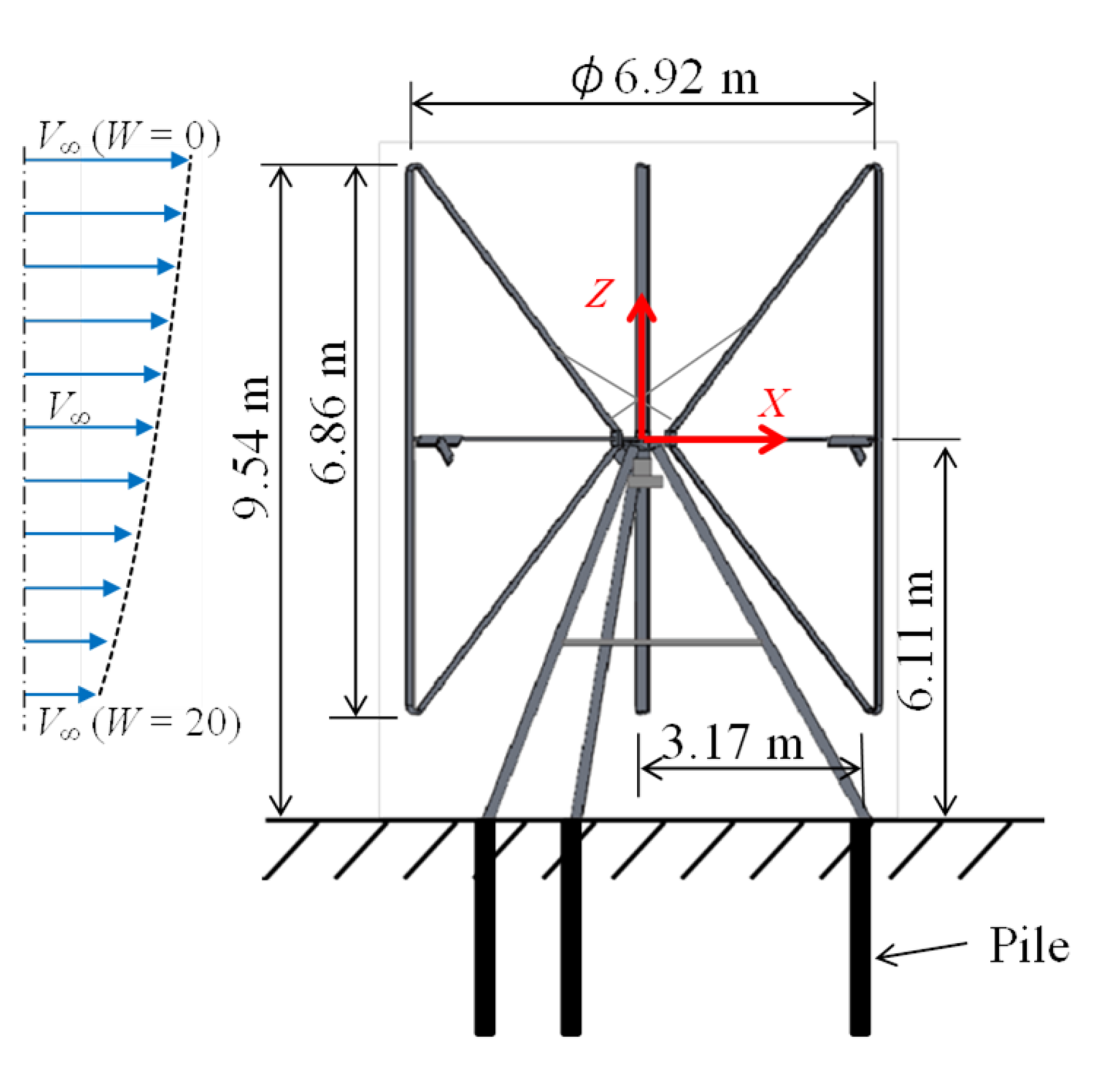
Figure 2 illustrates the outline and size of the prototype. Each movable arm was installed in one portion of the reinforcing horizontal arm, which spanned from the rotor hub to the center of the vertical main blade. An aileron is installed on the movable arm. The movable arm and aileron can rotate as one unit around the axis of the movable arm, as illustrated in Figure 1b. The slant angle η of the movable arm system (movable arm and aileron) changes depending on the balance among the centrifugal force, aerodynamic force, and gravity force acting on the movable arm and aileron, and when it is tilted greatly, large aerodynamic force, i.e., drag, acts on the movable arm to work as a passive aerodynamic brake for the wind turbine. When the wind speed and rotor rotational speed are low, the movable arm and aileron weights work as the recovering force to return to the initial state; therefore, no elastic devices such as springs are utilized. However, the movable arm system is inclined at an initial angle (ηini = 5°) as the initial state, and the movable arm is designed to tilt even at low rotational speeds when the wind speed is high. As illustrated in Figure 2, the trestle of the wind turbine is a tripod type, and its cross-sectional shape is the same as that of the mass-produced turbine currently under development (approximately half the length). The structure of the butterfly wind turbine does not have a concrete foundation but rather a pile foundation, which is easy to construct in a short construction period. The wind turbine blades, horizontal arm, including the movable arm system, hub, bearing housing, and tripod trestle, are all made of extruded aluminum.
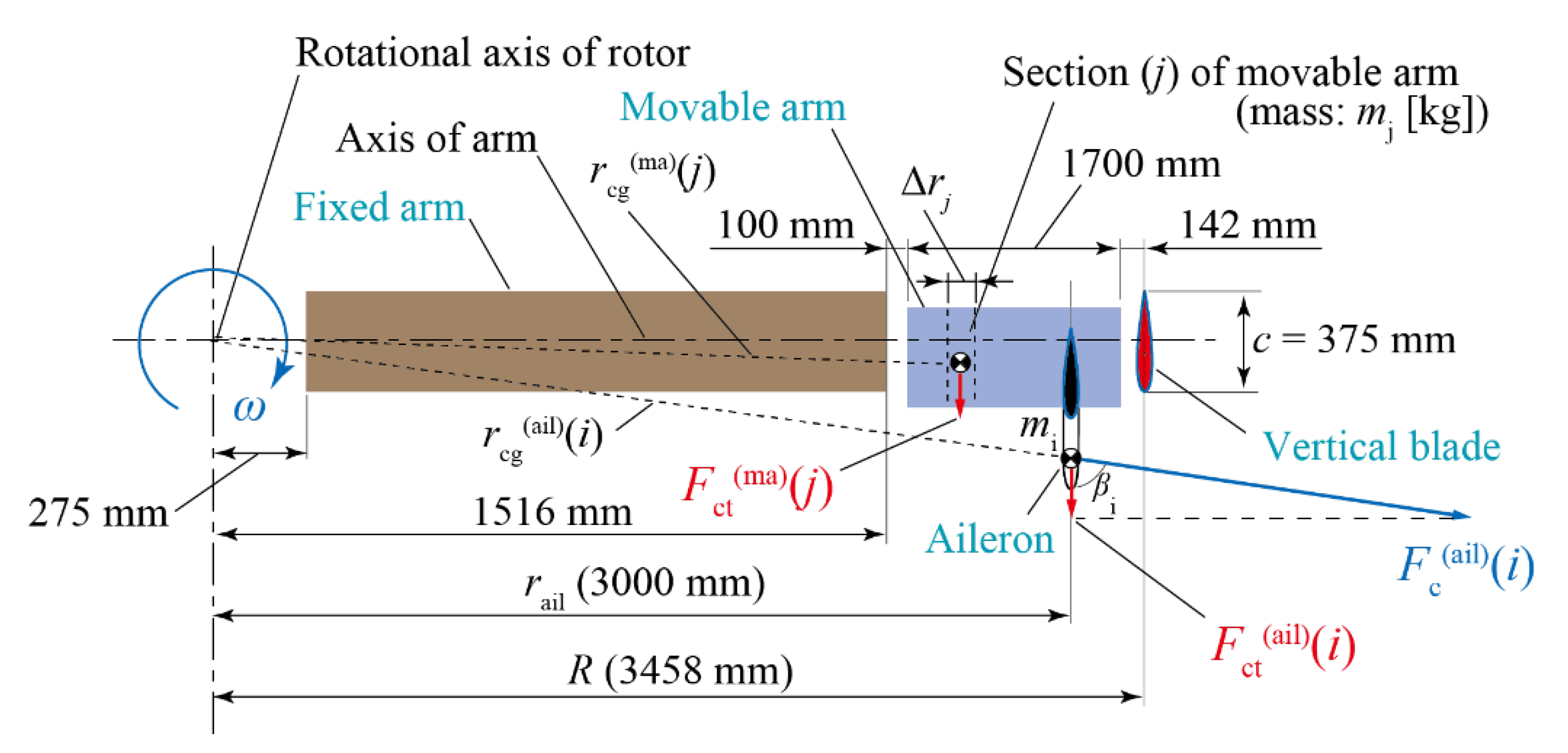
One of the purposes of installing this prototype was to confirm the behavior of the newly developed over-speed control system with movable arms to demonstrate its effectiveness. Although the prototype was designed to rotate up to approximately 100 rpm, for safety reasons, the lengths of the movable arm (1.7 m) and aileron (span(ail) = 0.6 m) were selected to realize a maximum rotor rotation of less than approximately 80 rpm as the first design. The movable arm, aileron, and fixed arm were made of the same aluminum extrusion shape as the main blade (common chord length, c = 375 mm). Figure 3 and Figure 4 present the main parameters and sizes of the prototype’s horizontal- and movable-arm systems, respectively. The prototype reuses the generator (rated output: 5 kW, with three times step-up gear) and control device used in a previously developed five-blade butterfly wind turbine (7 m diameter, 2.7 m height) [8]. Here, the load characteristics of the prototype rotor and generator (control targets) were inconsistent.
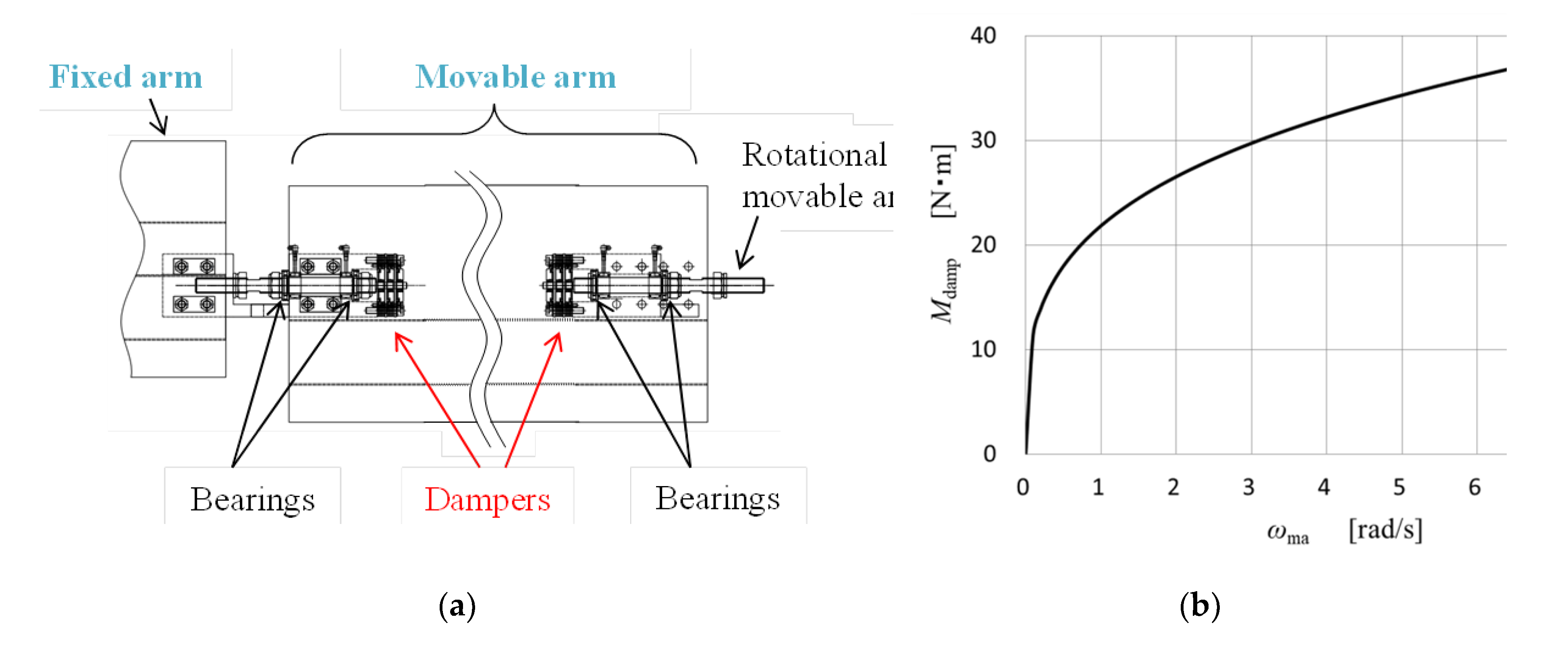
Bidirectional disk dampers (FDT-57A-503, Fuji Latex Co., Ltd.) were installed along the movable arm axis. Three-stacked dampers were placed on the movable arm’s left and right rotating shafts. Figure 5a illustrates the mounted parts of the dampers. Figure 5b presents the rotational angular velocity dependence of the total resistance moment (Mdamp) of the six disc dampers installed in one movable arm. Here, the total resistance moment is approximated using Equation (1) with reference to catalog values.
M d a m p = 6 × 3.6383 ω m a 0.2811
where ωma is the angular velocity of the tilting motion around the movable-arm axis.

3. Theoretical Prediction

3.1. Prediction of Flow Speed Distribution

The wind turbine characteristics were predicted employing a method based on the blade element momentum theory [11], adopting the quadruple multiple streamtube model [12]. Figure 6 presents a schematic of the flow-field calculation method. In this calculation, one stream tube was divided into upwind and downwind sides, and the stream tube of each side was divided into calculation parts of the outer and inner rotor intersectional wind speeds. Therefore, as demonstrated in Figure 6, along one stream tube, the intersectional wind speeds are calculated from the upstream wind speed V in the order of Vu_out, Vu_in, Vd_in, Vd_out to ensure a decreasing flow field. The flow field passing through the turbine rotor was divided into 180 stream tubes with widths corresponding to the unit azimuth angle in the horizontal direction, and the vertical direction was divided into 21 levels. The vertical level is represented by the integer parameter W, where W = 0 corresponds to the stream tubes at the top of the rotor, W = 20 at the bottom of the rotor, and W = 10 at the equatorial level (see Figure 2). In the analysis, the rotational direction of the wind turbine rotor was defined as counterclockwise, as viewed from above, which is opposite to that of the prototype. The origin of the azimuth angle Ψ is defined as the direction 90° from the upstream, and as illustrated in Figure 6, the upwind side is positive, and the downwind side is negative. In the in-house simulation code, an integer parameter I is introduced to specify the stream tube, and the origin of the parameter I (I = 0) is defined as the direction of Ψ = -180°. The value of I increases counterclockwise, and the final value (I = 360) corresponds to the stream tube in Ψ = 180°. The altitude distribution of the upstream wind speed is given by the power law defined by the following equation:
V z = V h u b z z h u b p
Here, p is the power index, which in this study was assumed to be p = 0.2. In the in-house simulation software, the upstream wind speed V corresponding to the hub height is given as Vhub in Equation (2) as an input condition, and the upstream wind speed V(W) at a height level W is calculated using Equation (2). Figure 2 demonstrates the altitude distribution of the upstream wind speed.
Aerodynamic data based on NACA 0018 data [13] were utilized for the present simulation because there are currently no reliable aerodynamic data for the novel airfoil (New_AF_1_UP). The reduction rate (7%) in the aerodynamic characteristics of the novel airfoil compared to NACA 0018 was considered [10] in the simulation. This study adopted the modified Gormont model [11] as the dynamic stall model. However, the effects of the dynamic stall were ignored in the ranges of 105° ≤ ψ ≤ 180° and -180° ≤ ψ ≤ -135°, where the degree of turbulence is assumed to be large due to the influence of the vortices shed around ψ = 90°.
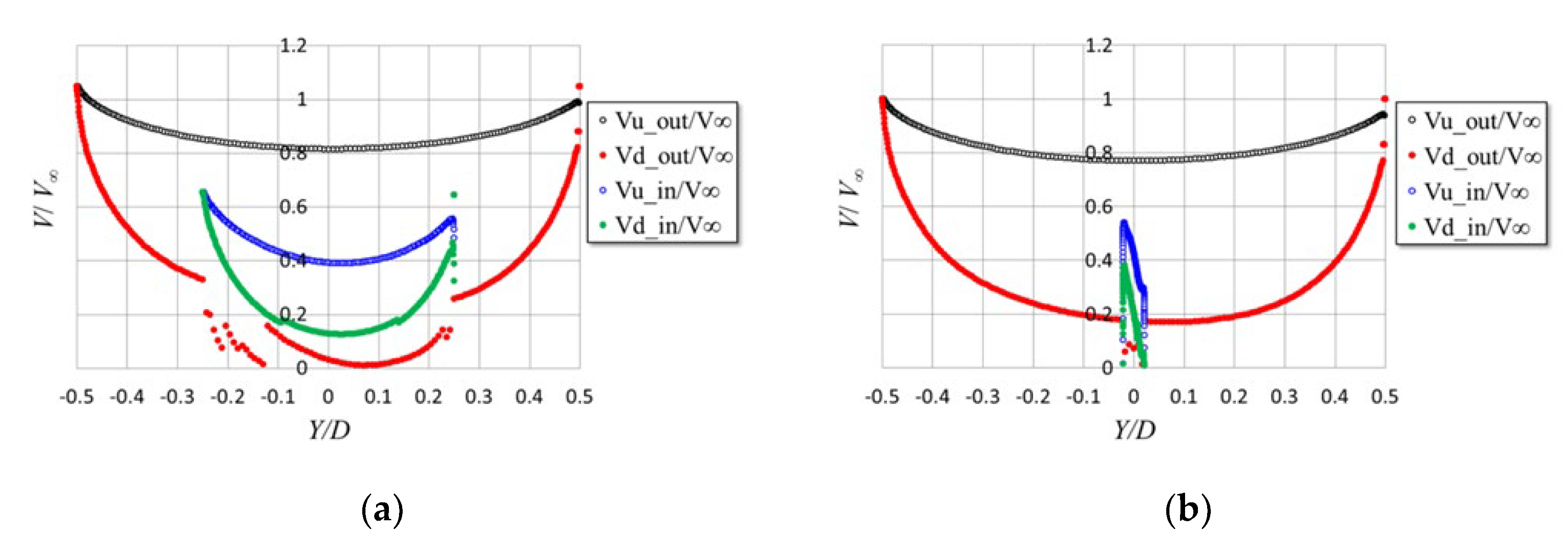
Figure 7 presents the wind speed distributions predicted at height levels of W = 5 and 10 under the conditions of the upstream hub-height wind speed of V = 6 m/s, the rotor rotation speed of N = 70 rpm, and the tip speed ratio of λ = 4.224 (λ = /V). The prediction demonstrates that the speed of the flow passing through the inner rotor (i.e., slant blades) is further reduced compared to that not passing through it. In addition, the position where the wind speed reached its minimum was slightly shifted from the center of the rotor to the positive side of the Y coordinate. In other words, the wind turbine converts more fluid energy into mechanical energy on the side where the blade moves from the downwind to the upwind side. In the simulation of the behavior of the movable arm described in Section 3.2, for simplicity, the outer rotor intersectional wind speeds (Vu_out and Vd_out) obtained at a hub height of W = 10 (see Figure 7b) were assumed to be the inflow speeds of the movable arm and aileron.

3.2. Equation of Motion of Movable Arm System

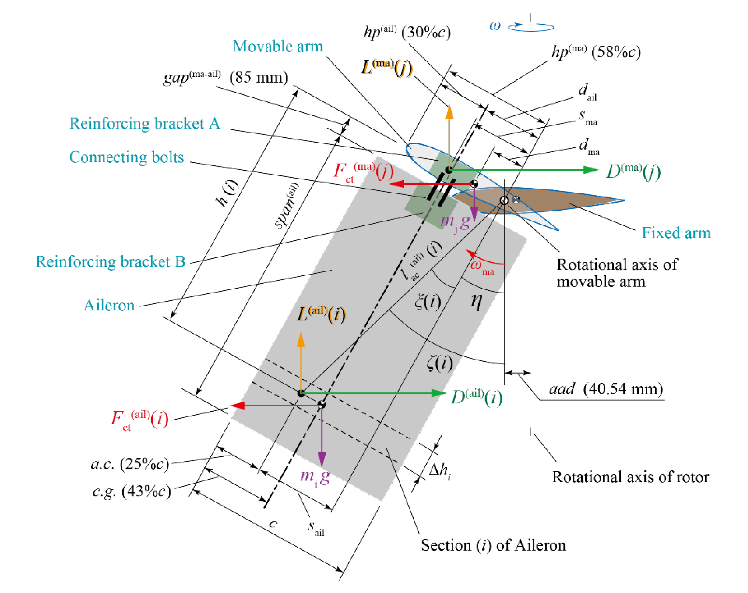
The simulation method for the behavior of the movable arm and aileron is described in this section. The aileron and movable arm were divided into 20 sections, and the mass of each section was defined as mi and mj. As illustrated in Figure 4, the length of the line segment connecting the aerodynamic center (a.c.) of the i-th section of the aileron and the movable arm axis is defined by Equation (3).
l a c ( a i l ) i = h ( i ) 2 + s a i l 2
where h(i) is the distance in the aileron span direction between the aerodynamic center of the i-th section and the movable arm axis, and sail is the distance in the chord direction. When there is no inclination (η = 0), the angle ξ(i) between the line segment lac(ail)(i) and the vertical direction is given by Equation (4).
ξ i = tan 1 s a i l / h ( i )
However, when there is an inclination (η ≠ 0), the angle ζ(i) between the line segment lac(ail)(i) between the vertical direction is given by Equation (5).
ζ i = ξ i + η
When the rotational angular velocity of the wind turbine is ω, the centrifugal force acting on the i-th section of the aileron is given by Equation (6).
F c a i l ( i ) = m i r c g a i l ( i ) ω 2
where rcg(ail)(i) is the distance between the wind turbine rotation axis and the center of gravity of the i-th section. The tangential component of the centrifugal force to the orbital circle of the rotor is expressed by Equation (7).
F c t a i l i = F c a i l i cos β i = m i ω 2   h i sin η + d a i l cos η + a a d
Here, βi is the angle between the direction of centrifugal force and the tangential direction, and dail is the distance in the chord direction between the movable arm axis and the center of gravity of the i-th section. The axis-axis-distance (aad) is the horizontal distance viewed from the movable arm axis direction between the movable arm axis and the wind turbine rotation axis; aad = 40.54 mm. Similar to Equations (6) and (7), the centrifugal force acting on the j-th section of the movable arm and its tangential component are given by Equations (8) and (9), respectively.
F c m a ( j ) = m j r c g m a ( j ) ω 2
F c t m a j = F c m a j cos β j = m j ω 2   d m a cos η + a a d
Here, dma is the distance in the chord direction between the movable arm axis and the center of gravity of the movable arm.
The vertical upward force L(ail)(i) and horizontal force D(ail)(i) acting on the aerodynamic center of the i-th section of the aileron, as illustrated in Figure 4, are expressed by Equations (10) and (11), respectively.
L a i l i = L α i sin α i D α i cos α i sin η
D a i l i = L α i sin α i + D α i cos α i cos η
Similarly, the vertical upward force L(ma)(j) and horizontal force D(ma)(j) acting on the aerodynamic center of the j-th section of the movable arm are given by Equations (12) and (13), respectively.
L m a j = L α j cos α j + D α j sin α j
D m a j = L α j sin α j + D α j cos α j
The lift forces (L(αi), L(αj)) and drag forces (D(αi), D(αj)) acting on each section, the angles of attack (αi, αj), and the angle Δαj, which are expressed on the right-hand side of Equations (10)–(13) are derived in Appendix A and Appendix B.
The moment Mc(ail) around the movable arm axis due to the centrifugal force acting on the aileron is determined by adding the contributions from all aileron sections (i = 0 to 19) and is given by Equation (14).
M c a i l = i F c t ( a i l ) ( i ) h ( i ) cos η d a i l sin η
The moment Mg(ail) around the movable arm axis owing to gravity acting on the aileron is determined by Equation (15).
M g a i l = i m i g h ( i ) sin η + d a i l cos η
The moment Maero(ail) around the movable arm axis owing to the aerodynamic force acting on the aileron is expressed by Equation (16), using the forces in Equations (10) and (11), respectively.
M a e r o a i l = i L ( a i l ) ( i ) l ac ail i   sin ζ i D ( a i l ) ( i ) l ac ail i cos ζ i
The moments around the movable arm axis caused by the centrifugal, gravitational, and aerodynamic forces acting on the movable arm (Mc(ma), Mg(ma), and Maero(ma)) were similar to those in Equations (14)–(16), determined by adding the contributions from all the movable arm sections (j = 0 to 19) and is given by Equations (17)–(19), respectively.
M c m a = j F c t ( m a ) ( j ) d m a sin η
M g m a = j m j g d m a cos η
M a e r o m a = j L ( m a ) ( j ) s ma cos η + D ( m a ) ( j ) s ma sin η
As demonstrated in Figure 4, the ailerons and movable arms include members considered concentrated masses, such as reinforcing brackets and connection bolts. Using information on their masses and positions relative to the movable arm axis, the moments around the movable arm axis caused by the centrifugal force and gravity acting on the concentrated masses (Mc(cm) and Mg(cm)) were calculated. In this case, the total moments Mc and Mg due to the centrifugal force and gravity acting on the aileron, movable arm, and concentrated mass are given by Equations (20) and (21), respectively.
M c = M c a i l + M c m a + M c c m
M g = M g a i l + M g m a + M g c m
Because it can be assumed that almost no aerodynamic force acts on the concentrated mass, the moment Maero due to the aerodynamic forces acting on the aileron and movable arm is expressed by Equation (22).
M a e r o = M a e r o a i l + M a e r o m a
The moment of inertia around the movable arm axis is defined by Ima, considering all aileron, movable arm, and concentrated masses. When the rotational angular velocity of the movable arm around the movable arm axis is ωma (clockwise direction is defined as positive), the equation of motion of the movable arm system (aileron + movable arm + concentrated masses) is as follows:
I m a d ω m a d t = M c + M g + M a e r o + M d a m p
The fourth term on the right-hand side of Equation (23) is the damper’s resistance moment, as defined in Equation (1) and always has the opposite sign to the sign of the rotational angular velocity ωma.

3.3. Prediction of Movable Arm Behavior and Rotor Performance

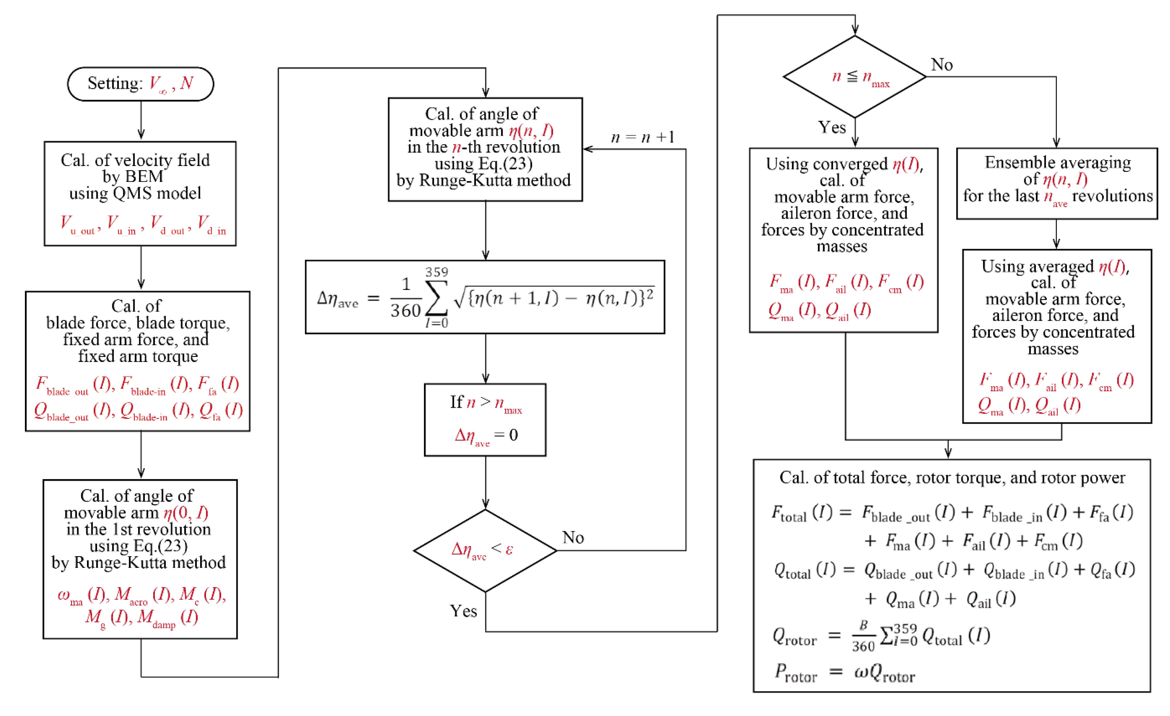
The simulation method developed here calculates the forces acting on each portion of the wind turbine and the average rotational torque and output produced by the turbine rotor when given the wind speed and rotor rotational speed. However, to determine the slant angle of the movable arm at each azimuth, the equation of motion of the movable-arm system expressed in Equation (23) was solved as a pseudo-unsteady problem to obtain the convergence state. A flowchart of the calculations is presented in Figure 8.
The upstream wind speed V at the hub height and the rotor rotational speed N are input as calculation conditions. The flow speeds (Vu_out, Vu_in, Vd_in, Vd_out) in each streamtube were calculated based on blade element momentum theory. At this stage, the forces (Fblade_out(I), Fblade_in(I), Ffa(I)) and torques (Qblade_out(I), Qblade_in(I), Qfa(I)) at each azimuth of the outer blade (vertical blade), inner blade (slanted blade), and fixed arm were obtained without movable arms. The equation of motion of the movable-arm system in Equation (23) is numerically integrated to determine the inclination angle η(n, I) at each azimuth of the n-th rotation. As initial values, the azimuth angle is set as Ψ = -180°, the inclination angle is set as η(0,0) = ηini, and the inclination angular velocity is set as ωma = 0 rad/s. The fourth-order Runge–Kutta method was used for the numerical integration. After the second rotation, the convergence degree ∆ηave of the inclination angle is checked with Equation (24) each time the calculation for one rotation was completed.
η a v e = 1 360 I = 0 359 η n + 1 ,   I η n ,   I 2
If ∆ηave becomes smaller than a certain constant value ε (ε = 0.2 here), the variation of the slant angle during one revolution is considered to become periodic to stop the calculation. In this case, the value of the inclination angle at the final rotation is defined as η(I). However, if the inclination angle variation does not converge even as reaching the maximum number of rotations nmax for calculation (nmax = 30 here), the slant angle η(n, I) is ensemble averaged for each azimuth over the last nave revolutions to determine the pseudo-converged inclination angle η(I). Thus, once the inclination angle of the movable arm is determined, the forces (Fma(I), Fail(I), Fcm(I)) at each azimuth owing to the movable arm, aileron, and concentrated mass can be calculated. For the movable arm and aileron, the torques around the rotor rotation axis (Qma(I), Qail(I)) were also calculated. Therefore, the rotational torque Qtotal(I) of a blade at the azimuth of integer parameter I is given by Equation (25).
Q t o t a l I = Q b l a d e _ o u t I + Q b l a d e _ i n I + Q f a I + Q m a I + Q a i l I
When the number of blades is B (B = 3 in the prototype), the average rotor torque Qrotor and the rotor output Protor are expressed by Equations (26) and (27), respectively.
Q r o t o r = B 360 I = 0 359 Q t o t a l I
P r o t o r = ω Q r o t o r
If the rotor-swept area is A (A = 47.4 m2 for the prototype), then the power coefficient Cp is given by Equation (28).
C p = P r o t o r 0.5 ρ V 3 A = ω Q r o t o r 0.5 ρ V 3 A
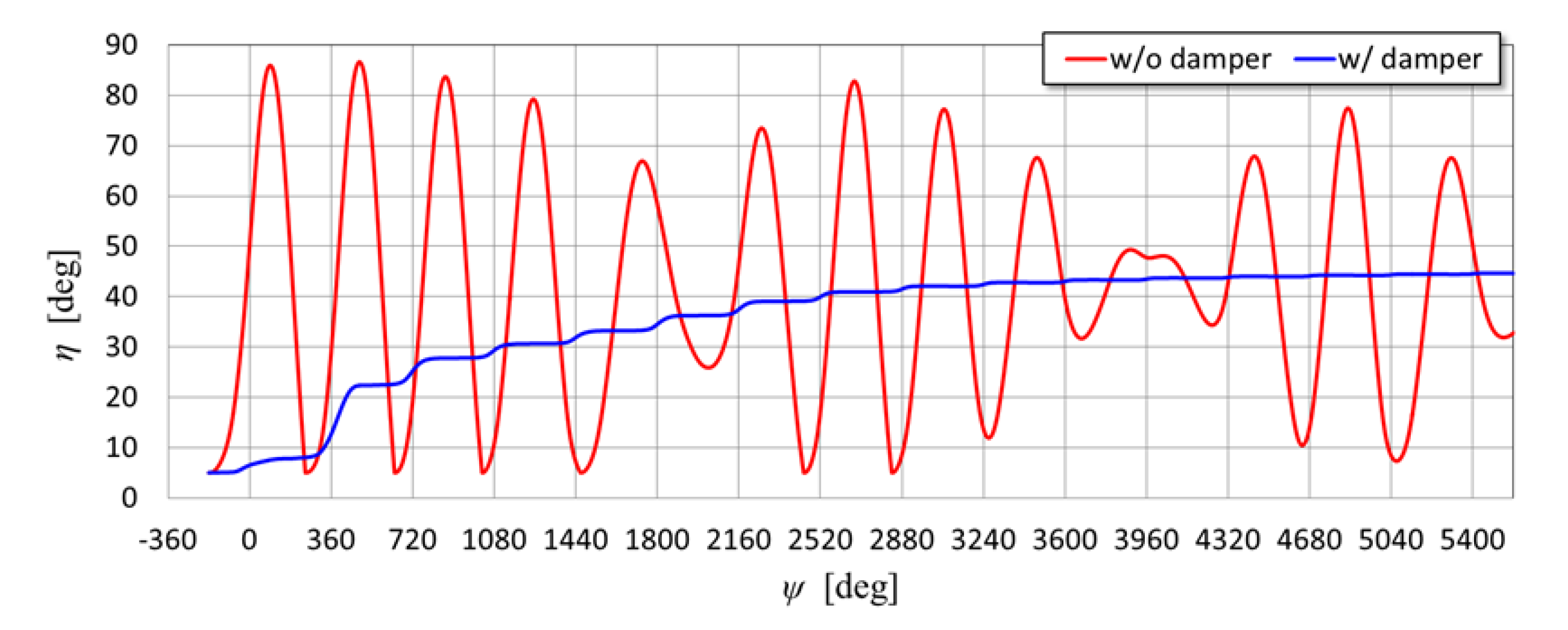
Figure 9 presents the predicted variations in the inclination angle of the movable arm when the wind speed is V = 6 m/s, the rotor rotational speed is N = 70 rpm, and the tip speed ratio is λ = 4.224. The red and blue curves represent the cases without and with dampers, respectively. In the case with dampers, the inclination angle of the movable arm almost converged to a value of about 44.6° after the rotor rotation of 15 times (the cumulative azimuth angle corresponds to Ψ = 5400°). In contrast, in the case without dampers, the variation in the slant angle did not converge, even at a maximum rotation number of 30. In this case, the prediction presented in Figure 9 illustrates that the azimuth of the maximum slant angle for each rotation gradually changes. However, depending on the combination of wind and rotational speeds, even without dampers, the variation in the slant angle converges within a few rotor rotations.
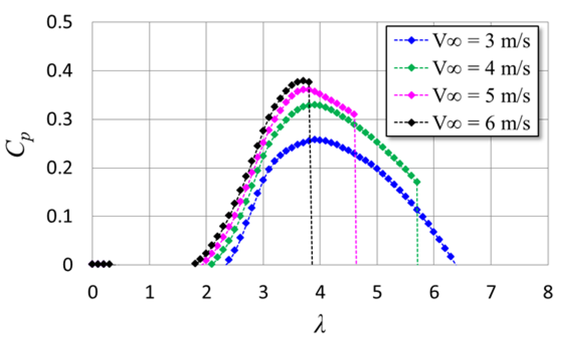
Figure 10 presents the prediction results of the power coefficient for the prototype at wind speeds of V = 3, 4, 5, and 6 m/s. At V = 3 m/s, the movable arms do not tilt, but at V = 4 m/s or more, the movable arms tilt, and when a certain tip speed ratio is exceeded, the aerodynamic brake works, followed by a sudden decrease in the power coefficient.

4. Experimental Setup

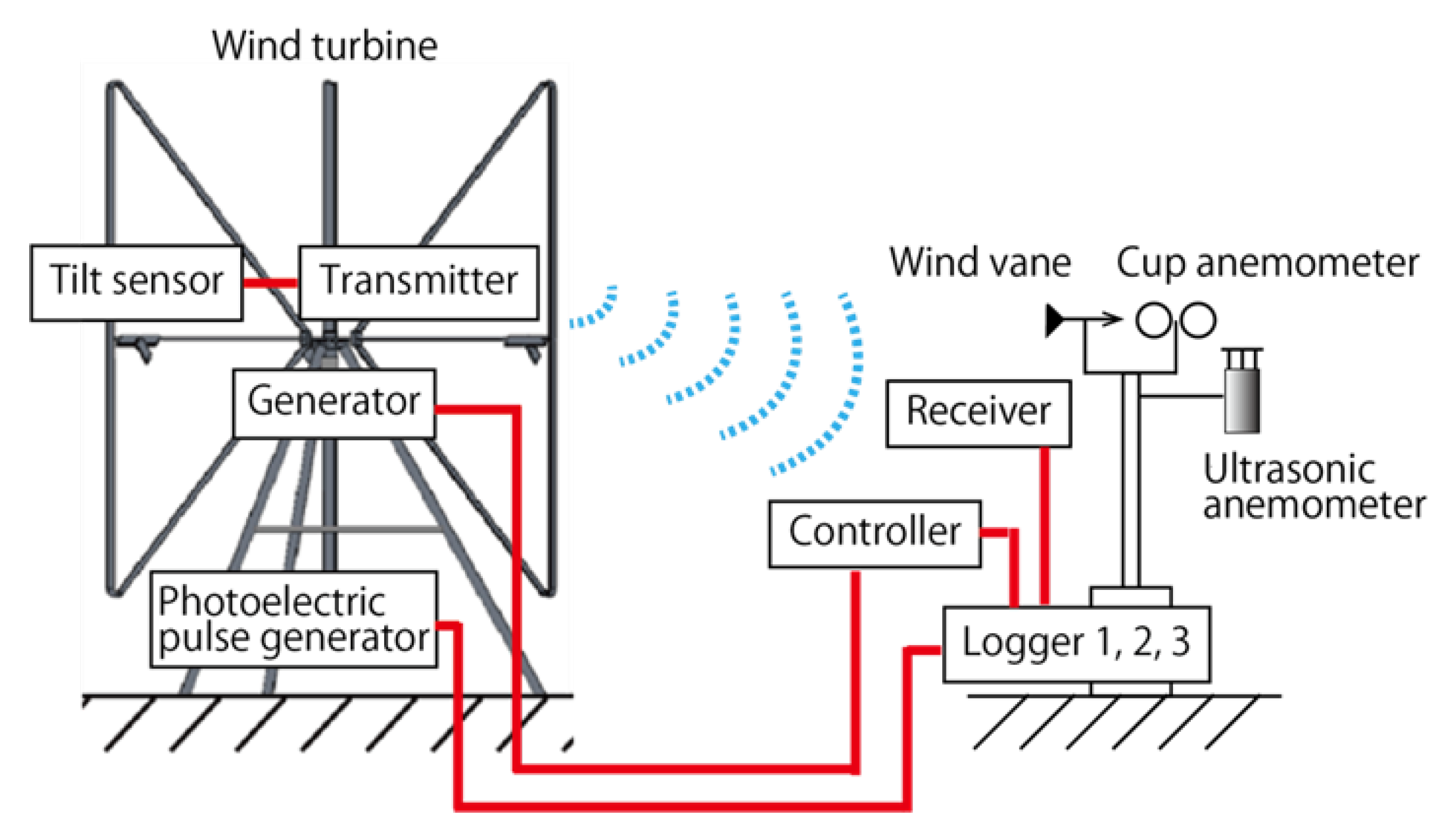
Figure 11 presents a schematic of the measurement system. The prototype has three movable arms; however, a tilt sensor (M21-0455, Kyowa Electronic Instruments Co., Ltd.) is installed on only one. Power was supplied to the tilt sensor by a solar panel and a battery installed on the hub. The measurement data of the tilt sensor were transmitted via radio waves and recorded at a sampling rate of 20 Hz using a Logger-2 (GL840, Graphtec Corp.) installed on a wind measurement pole approximately 15 m from the wind-turbine center axis. A reflector plate was installed near the root of the oblique blade, which was located under the movable arm equipped with the tilt sensor. The light reflected from the reflector emitted by a photoelectric sensor (E3Z-R61, OMRON Corp.) installed in the tripod trestle was used to determine the azimuth of the movable arm mounting the tilt sensor via linear interpolation between pulses generated once per rotation. The wind observation pole was 5 m high, approximately the same as the hub height. A set of cup anemometers, wind vanes (CYG-3002VM, CLIMATEC Inc.), and a two-dimensional ultrasonic anemometer (CYG-85000, CLIMATEC Inc.) were installed at the pole to measure wind condition data. Logger-1 (sampling rate: approximately 0.67 Hz), built into the wind turbine control panel, records the wind direction and speed data measured by a two-dimensional ultrasonic anemometer, generator voltage and current, and generator rotational speed. The data measured by the cup anemometer and wind vane were synchronously recorded along with the pulse signal of the photoelectric sensor using Logger-2, which recorded the inclination angle of the movable arm system. In addition, another Logger-3 (GL240, Graphtec Corp.) was installed, which recorded the wind direction and speed data from the two-dimensional ultrasonic anemometer, the voltage and current of the generator, and the wind turbine rotational speed at a sampling rate of 1 Hz. Although there are some differences between the data from the different measuring instruments and loggers, it has been confirmed that the values for the same physical quantities are almost identical. The time lag between the loggers was corrected by shifting the time axis of the data or performing interpolation as necessary.

5. Results and Discussion

5.1. Comparison of Behavior of Movable Arm between with and Without Dampers

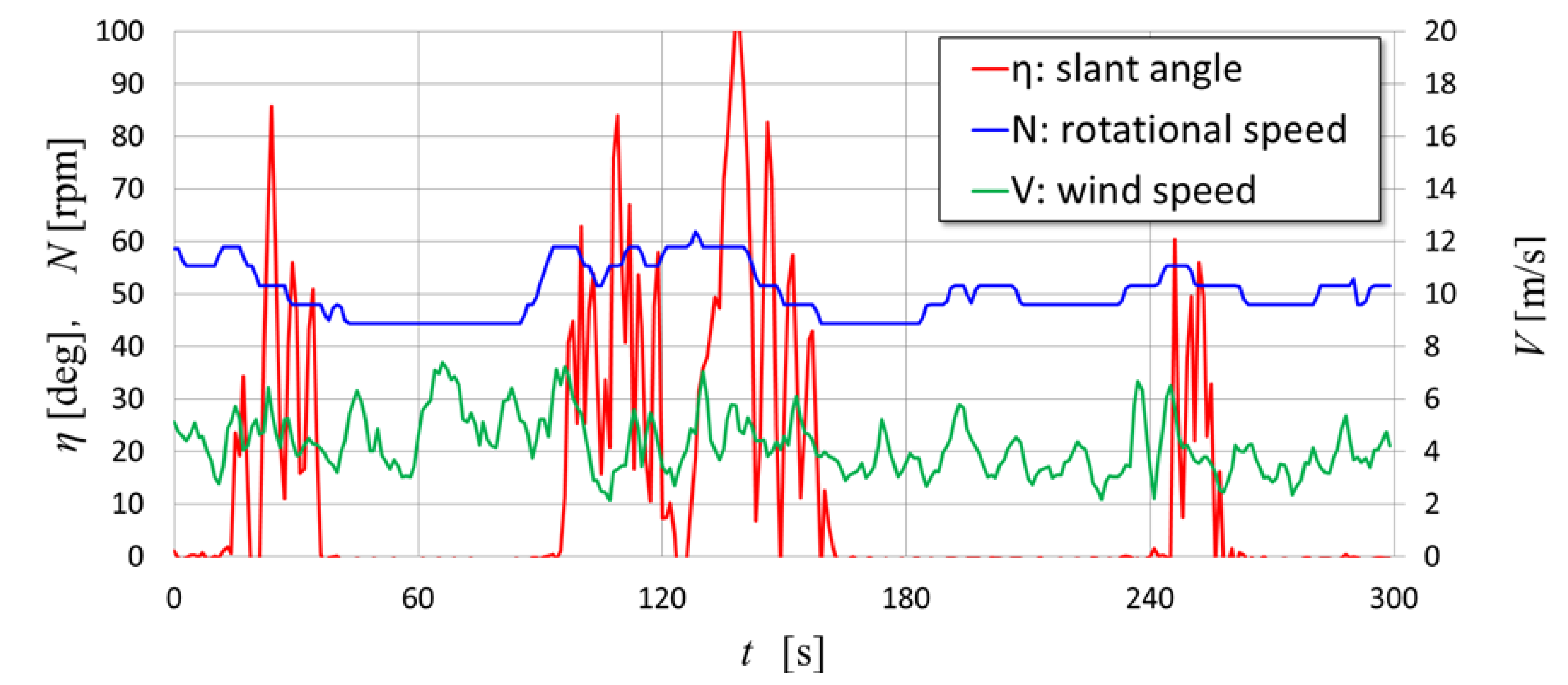
Figure 12 demonstrates typical behavior of the slant angle η of the movable arm in the case without dampers. The measured data (obtained with Logger-2) in Figure 12 correspond to 5 min (300 s) from 00:01:00 to 00:06:00 on April 16, 2022. The red, blue, and green curves represent the slant angle, rotational speed, and wind speed, respectively. When the rotational speed exceeded approximately 55 rpm, the movable arm tilted significantly to suppress the increase in rotational speed; however, the movable arm repeatedly inclined violently up and down during one wind turbine rotation. Initially, the movable arm was equipped with stoppers (limiters) to limit the operating range of the tilt angle (5° ≤ η ≤ 90°). However, owing to the drastic variation in the tilt angle, the generation of an impact on the stoppers and significant noise were observed under the condition of high rotor rotation.
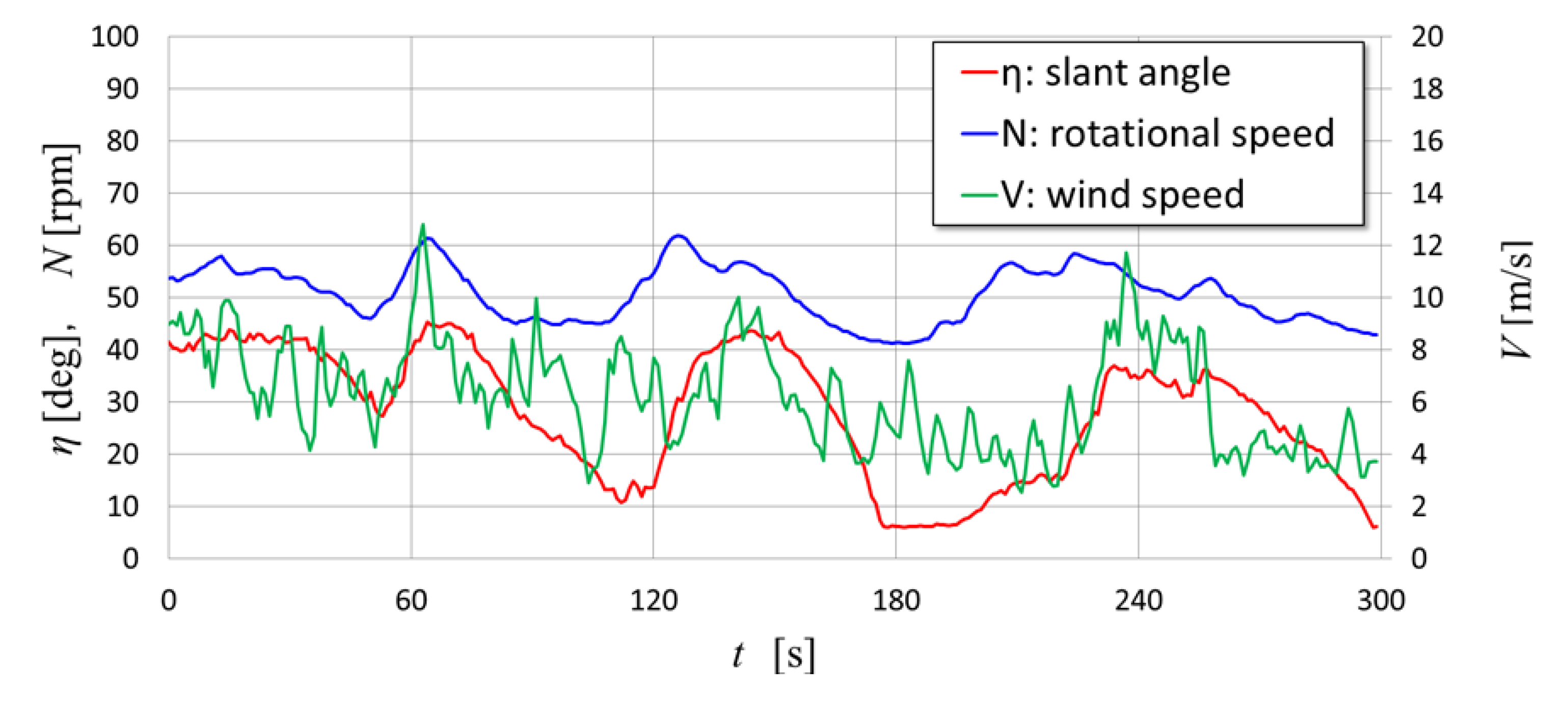
Figure 13 illustrates the behavior of the slant angle η in the case with dampers. The measured data in Figure 13 correspond to 5 min (300 s) from 15:33:00 to 15:38:00 on January 20, 2023, and the colored curves indicate the same physical quantities as illustrated in Figure 12. The tilting movement of the movable arm became gentle owing to the damper resistance torque. The impact on the stoppers and noise was almost negligible.
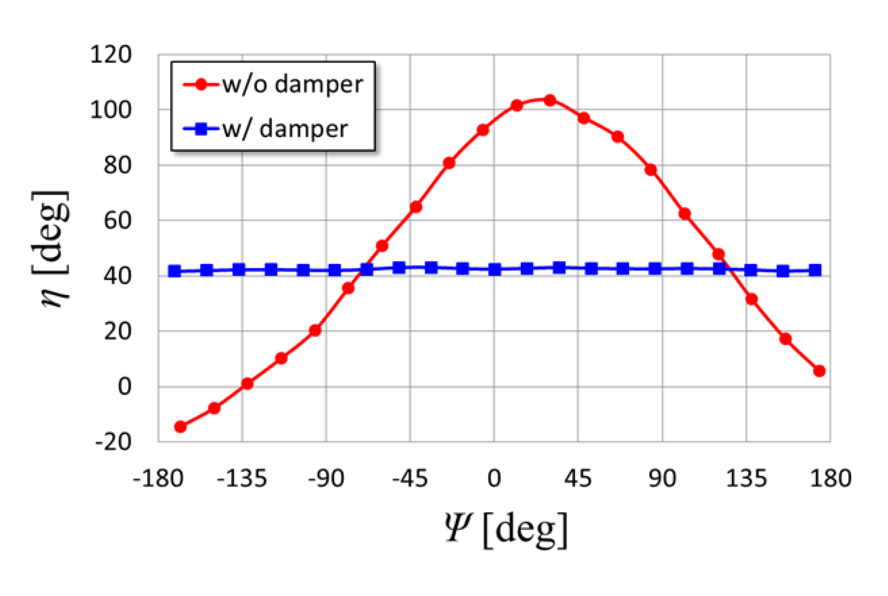
Figure 14 presents a graph comparing the azimuth dependence of the slant angle during one rotation of the wind turbine rotor with and without dampers (data obtained using Logger-2). The horizontal axis is the azimuth angle Ψ defined in Figure 6, and the red plot is without dampers (average value during one rotation: V = 5.4 m/s, N = 60.0 rpm, ηave = 48.6°), and the blue plot is the case with dampers (average value during one rotation: V = 9.6 m/s, N = 56.9 rpm, ηave = 42.4°). In the case without dampers, the slant angle varies by one period during one rotation. The measured slant angle exceeds the range limited by the stoppers. Accelerations exceeding the tolerance of the tilt sensor probably caused a large error in the measurement of the tilt angle. When the wind speed is relatively high (V > 5 m/s), the maximum slant angle in the case without dampers occurs around Ψ = 30° as illustrated in Figure 14. However, when the wind speed is low, the peak slant angle may occur near Ψ = ±180°; the behavior of the movable arm without dampers changes greatly depending on the wind speed and rotational speed [9]. However, in the case of the dampers, the slant angle remained approximately constant during one rotor rotation. In the data presented in Figure 14, the average wind speed was rather high at 9.6 m/s; however, the rotor rotational speed was suppressed to 56.9 rpm owing to the stable slant angle in one revolution due to the effects of the dampers.

5.2. Comparison of Wind Speed Dependence of Rotational Speed between Prediction and Experiments

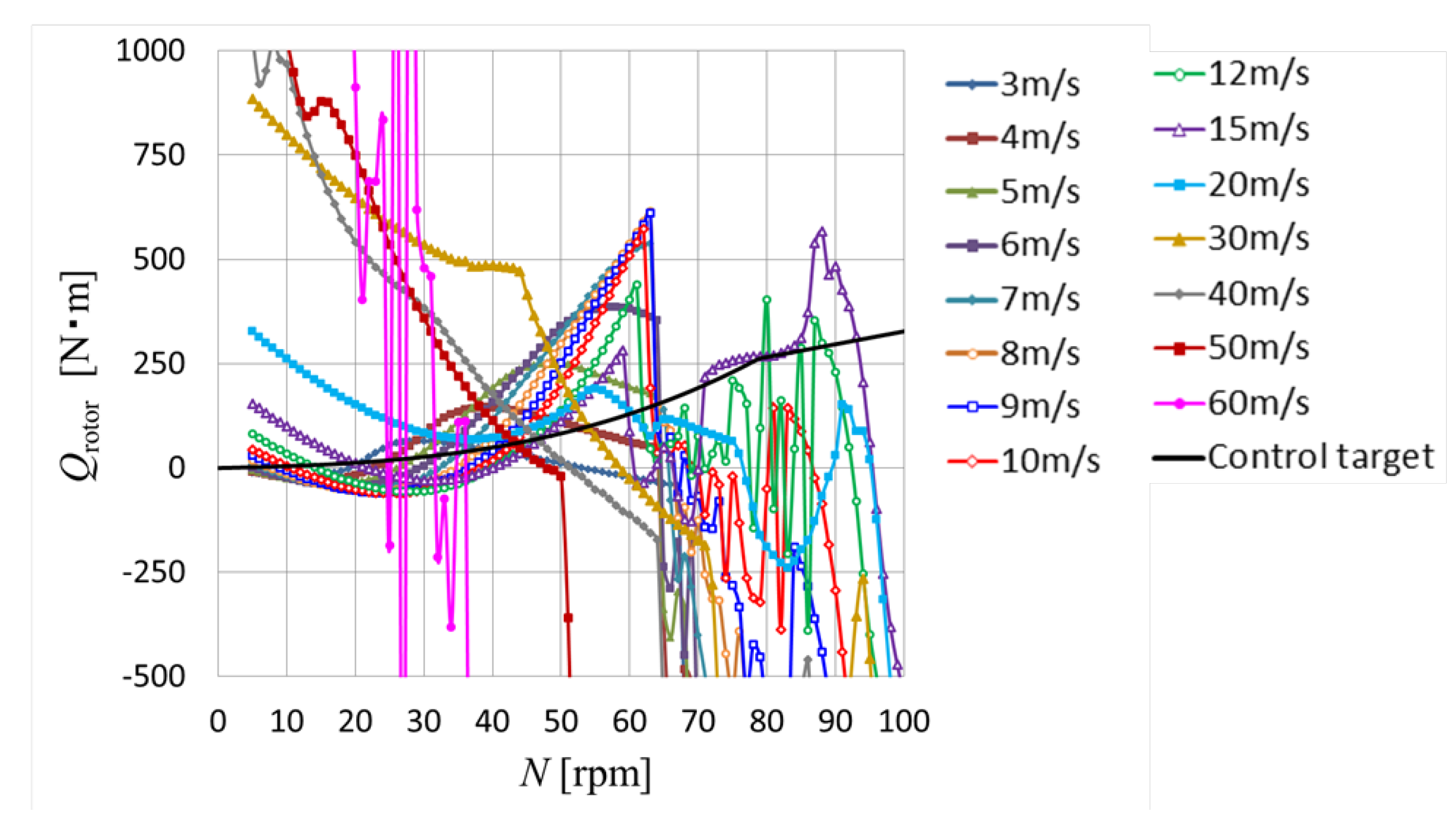
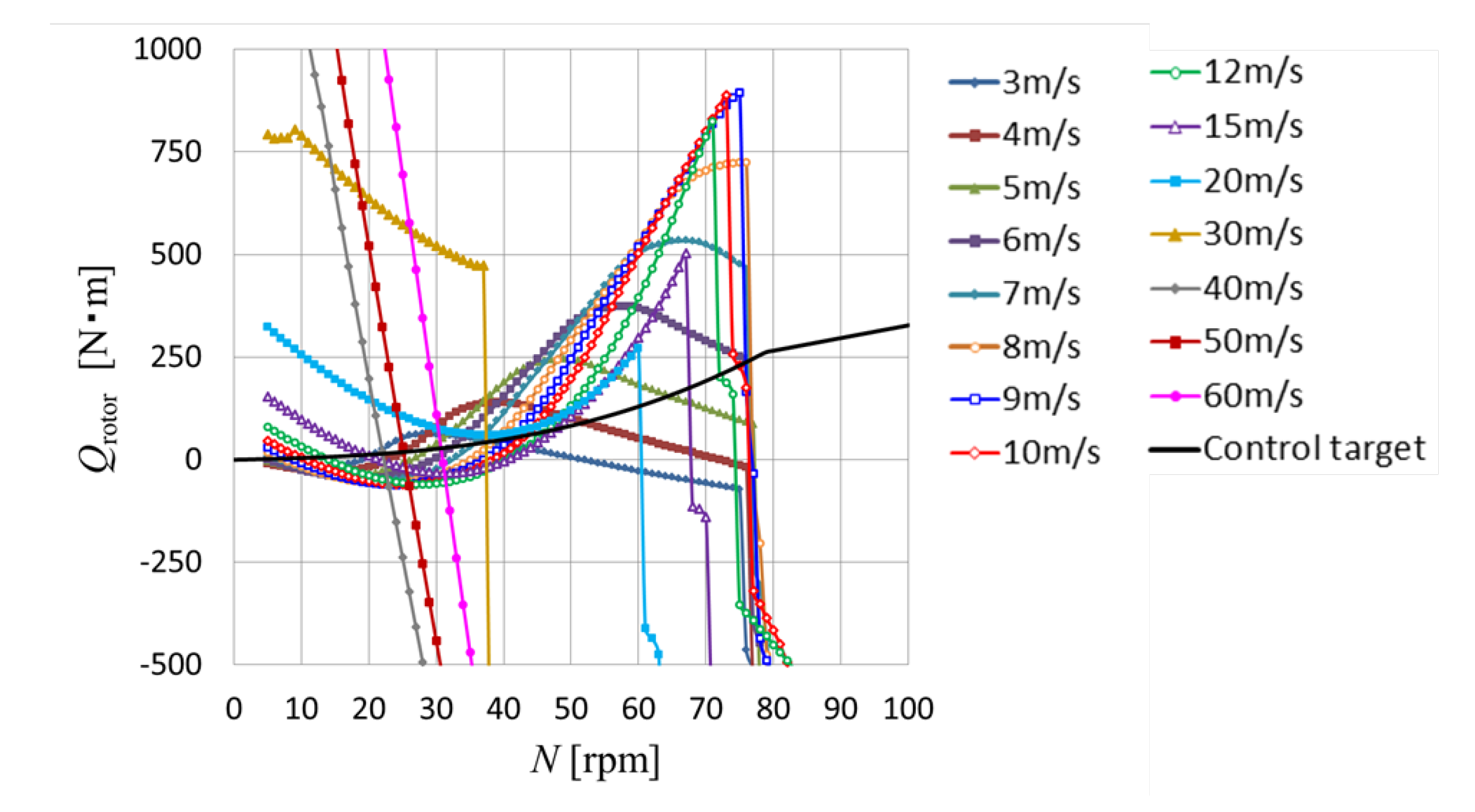
Figure 15 presents the predicted torque characteristics of the prototype with movable arms using ailerons with a span(ail) of 600 mm in the absence of dampers. The calculation of the averaged rotor torque using Equation (26) was performed by setting the wind speed from 2 to 60 m/s at 1 m/s intervals and changing the rotor rotational speed from 5 to 100 rpm at 1 rpm intervals for each condition. However, only the torque curves of the main wind speeds are depicted in Figure 15 to avoid complications. The black curve in the figure represents the control target and corresponds to the generator’s load torque, including the three-time speed increaser. As mentioned previously, the current control target was inconsistent with the torque characteristics of the prototype.
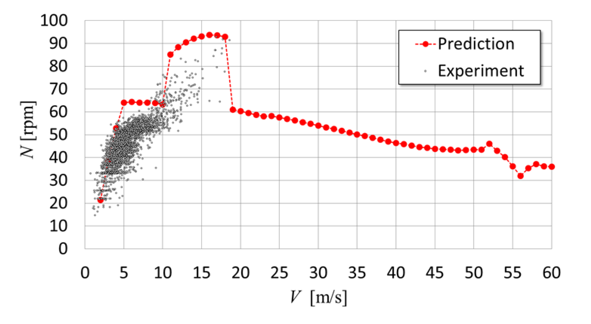
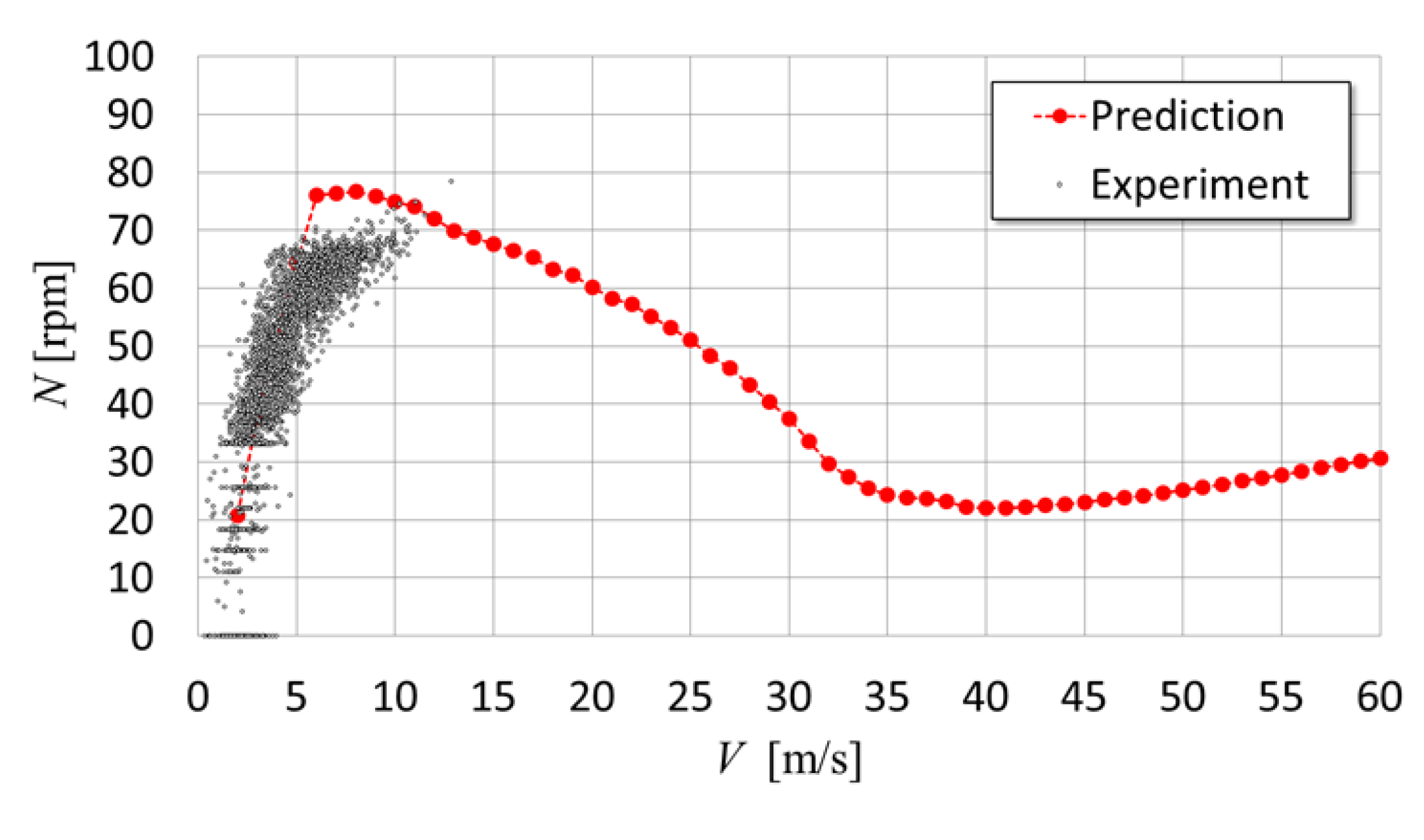
The intersection of the control target and rotational torque curve at each wind speed predicts the operating point. Figure 16 compares the predicted and measured wind speed dependencies of the rotor rotational speed in the prototype without dampers. The measurement data were the 20-s moving average value of the rotor rotational speed obtained by Logger-1 during the 24-hour period from 12:00 on September 5, 2022, to 12:00 on September 6, 2022, including strong wind conditions with a typhoon approaching. However, in Logger-1, the generator rotational speed is determined from the voltage frequency of the generator. The generator speed is multiplied by the speed increase rate to obtain the rotational speed of the wind turbine. The theoretical prediction demonstrated an almost constant rotational speed of approximately 65 rpm in the wind speed range of 5–10 m/s. However, it rapidly increased to 85 rpm at a wind speed of 11 m/s, followed by high rotational speeds of over 90 rpm in the wind speed range of 13–18 m/s. However, the measurement data demonstrated scattering, with a maximum rotor speed of approximately 60 rpm at a wind speed of 8 m/s or less. When the wind speed exceeded 8 m/s, the maximum rotational speed of the measurements increased to approximately 90 rpm. There were quantitative discrepancies between the measurements and predictions; however, they exhibited qualitatively consistent trends.
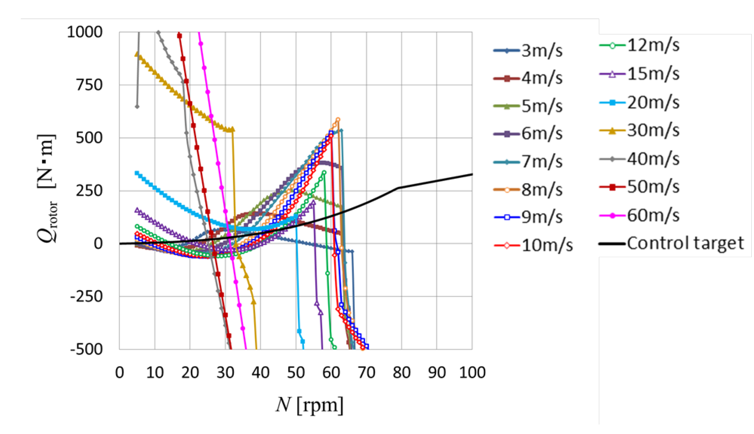
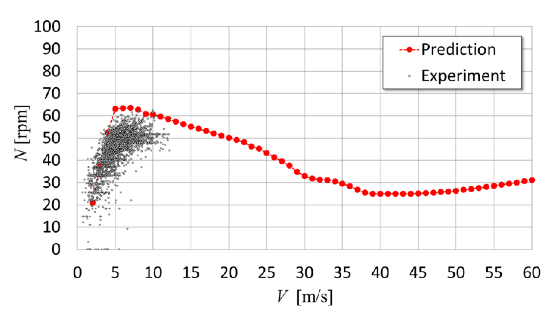
Figure 17 presents the predicted torque characteristics of the prototype with ailerons of span(ail) = 600 mm and dampers, which are depicted in the same manner as in Figure 15. Figure 18 presents the measured values for the case with dampers and the prediction. The data were obtained with Logger-1 during the 24-hour period from 12:00 on January 24, 2023, to 12:00 on January 25, 2023, when a large cold wave arrived and strong winds occurred. As illustrated in Figure 18, the plot of the measurement data corresponds to the 20-s moving average of the rotor rotational speed. The theoretical predictions and measured data were in good quantitative agreement, with a maximum rotor speed of approximately 60 rpm in the wind speed range of 5–10 m/s.

5.3. Prediction and Experimental Data after Replacement with Short Ailerons

Figure 19 presents the theoretical prediction of the torque characteristics of the prototype when the aileron length was set to span(ail) = 400 mm in the case with the dampers. Compared to Figure 17, the maximum value of the predicted torque curve increases, and the maximum rotational speed at the operating points also increases by shortening the aileron length. Similar to Figure 18, in Figure 20, the wind-speed dependence of the rotor rotational speed predicted from the torque characteristics in Figure 19 is compared with the rotational speed data measured in the prototype. The measurement data are the 20-s moving average value of the rotor rotational speed obtained by Logger-1 during the 24-hour period from 00:00 on August 15, 2023, to 00:00 on August 16, 2023, including strong wind conditions with a typhoon approaching. The theoretically predicted maximum rotational speed for the aileron length of 600 mm is 63.6 rpm at the wind speed of 7 m/s. However, for the aileron length of 400 mm, the predicted maximum rotational speed is 76.6 rpm at the wind speed of 8 m/s. In the measured data, when the aileron length was short, there was a slight tendency for the rotational speed to increase at a wind speed of approximately 10 m/s. However, even in the measurement data, changing the aileron length from 600 mm to 400 mm increased the maximum rotational speed by approximately 10 rpm, which roughly agrees with the prediction. However, with regard to the data measured with the dampers, data at average wind speeds of 15 m/s or higher were not obtained. Therefore, comparisons with theoretical predictions are impossible. In high-wind conditions, demonstrating the effectiveness of both the movable arm with dampers and predicting the behavior are topics for future studies.

6. Conclusions

A small vertical-axis-type butterfly wind turbine prototype (6.92 m in diameter) equipped with a novel over-speed-control system with movable arms was developed. To improve the system characteristics, several disk dampers were installed on the rotating axis of each movable arm. To predict the performance of the prototype, including the movement of the movable arms, we developed a prediction method that combines a flow field analysis based on the blade element momentum theory with an analysis of the equation of motion of the movable arm. The prediction of the behavior of the movable arm using the developed method demonstrated that without dampers, the slant angle variation of the movable arm may not converge; however, with dampers, it converges to a constant value. The measurement results of the slant angle of a movable arm in field experiments of the prototype demonstrated that the slant angle varies significantly during one rotor rotation and reaches a maximum when the movable arm moves from the downwind side to the upwind side without dampers and at a relatively high wind speed (5 m/s or more). However, in the case with the dampers, the slant angle remained almost constant during one rotor rotation, and the variation in the slant angle due to changes in the wind speed was slow. The impact on the stopper and noise generation, problems without dampers, was resolved by introducing dampers. The theoretical predictions were compared with the measured data regarding the dependence of the rotor rotational speed on the wind speed in the cases with and without dampers or in the case of a shorter aileron span. The predictions demonstrated almost quantitative agreement with the measurements. In the prototype, changing the aileron span length from 600 to 400 mm increased the maximum rotor speed by approximately 10 rpm.

Author Contributions

Conceptualization, S.S. and Y.H.; methodology, Y.H.,S.S.,H.I. and T.O.; software, Y.H. and T.O.; validation, S.S.,H.H.,H.I.,T.O.,K.I. and K.Y.; formal analysis, Y.H. and T.O.; investigation, Y.H.,K.I. and K.Y.; resources, H.H.,H.I. and T.O.; data curation, Y.H.,H.H.,H.I. and T.O.; writing—original draft preparation, Y.H.; writing—review and editing, S.S. and H.H.; visualization, Y.H.; supervision, S.S.; project administration, H.H.; funding acquisition, Y.H. and H.H. All authors have read and agreed to the published version of the manuscript.

Funding

This research was conducted jointly at Tottori University and Nikkeikin Aluminum Core Technology Co., Ltd.

Data Availability Statement

The data presented in this study are available on request from the corresponding author.

Acknowledgments

The field experiments of the butterfly wind turbine were carried out at the Arid Land Research Centre (ALRC) of Tottori University. The authors thank the related parties in ALRC.

Conflicts of Interest

The authors declare no conflict of interest.

Nomenclature

A Rotor swept area [m2]
aad Distance between rotor rotation axis and movable arm axis [m]
a.c.(i) Aerodynamic center of section i of aileron [-]
a.c.(j) Aerodynamic center of section j of movable arm [-]
B Number of blades [-]
CDi, Re) Drag coefficient of section i of aileron [-]
CDj, Re) Drag coefficient of section j of movable arm [-]
CLi, Re) Lift coefficient of section i of aileron [-]
CLj, Re) Lift coefficient of section j of movable arm [-]
Cp Power coefficient of wind turbine [-]
c Chord length [m]
D Diameter of wind turbine rotor [m]
D(ail)(i) Horizontal aerodynamic force of section i of aileron [N]
D(ma)(j) Horizontal aerodynamic force of section j of movable arm [N]
D(αi) Drag force of section i of aileron [N]
D(αj) Drag force of section j of movable arm [N]
dail Chordwise distance between center of gravity of aileron and movable arm axis [m]
dma Chordwise distance between center of gravity of movable arm and movable arm axis [m]
Fail(I) Force acting on an aileron in azimuth I [N]
Fblade_in(I) Force acting on an inner blade in azimuth I [N]
Fblade_out(I) Force acting on an outer blade in azimuth I [N]
Fc(ail)(i) Centrifugal force acting on section i of aileron [N]
Fc(ma)(j) Centrifugal force acting on section j of movable arm [N]
Fcm(I) Force acting on concentrated masses in azimuth I [N]
Fct(ail)(i) Tangential component of centrifugal force acting on section i of aileron [N]
Fct(ma)(j) Tangential component of centrifugal force acting on section j of movable arm [N]
Ffa(I) Force acting on a fixed arm in azimuth I [N]
Fma(I) Force acting on a movable arm in azimuth I [N]
Ftotal(I) Total force acting on a blade in azimuth I [N]
g Gravitational acceleration [m/s2]
gap(ma-ail) Distance between aileron top end and movable arm axis [m]
H Rotor height [m]
h(i) Distance between aerodynamic center of section i of aileron and movable arm chord line [m]
hp(ail) Holding point of aileron [m]
hp(ma) Holding point of movable arm [m]
Δhi Width of section i of aileron [m]
I Integer parameter of azimuth [-]
Ima Inertial moment of movable arm system around the axis [kgm2]
i Integer parameter specifying a section of aileron [-]
j Integer parameter specifying a section of movable arm [-]
L(ail)(i) Vertical aerodynamic force of section i of aileron [N]
L(ma)(j) Vertical aerodynamic force of section j of movable arm [N]
L(αi) Lift force of section i of aileron [N]
L(αj) Lift force of section j of movable arm [N]
lac(ail)(i) Distance between aerodynamic center of section i of aileron and movable arm axis [m]
Maero Total moment by aerodynamic forces acting on aileron and movable arm [N・m]
Maero(ail) Moment by aerodynamic force acting on an aileron [N・m]
Maero(ma) Moment by aerodynamic force acting on a movable arm [N・m]
Mc Total moment by centrifugal forces acting on aileron, movable arm, and concentrated mass [N・m]
Mc(ail) Moment by centrifugal force acting on an aileron [N・m]
Mc(cm) Moment by centrifugal force acting on concentrated mass [N・m]
Mc(ma) Moment by centrifugal force acting on a movable arm [N・m]
Mdamp Resistant moment of dampers [N・m]
Mg Total moment by gravity forces acting on aileron, movable arm, and concentrated mass [N・m]
Mg(ail) Moment by gravity force acting on an aileron [N・m]
Mg(cm) Moment by gravity force acting on concentrated mass [N・m]
Mg(ma) Moment by gravity force acting on a movable arm [N・m]
mi Mass of section i of aileron [kg]
mj Mass of section j of movable arm [kg]
N Rotor rotational speed [rpm]
n Number of rotor rotations [-]
nave Number of rotor rotations for ensemble averaging [-]
nmax Maximum number of rotor rotations for calculation of movable arm behavior [-]
Protor Power of wind turbine rotor [W]
p Index of power law of vertical distribution of wind speed [-]
Qail(I) Torque generated by an aileron in azimuth I [N・m]
Qblade_in(I) Torque generated by an inner blade in azimuth I [N・m]
Qblade_out(I) Torque generated by an outer blade in azimuth I [N・m]
Qfa(I) Torque generated by a fixed arm in azimuth I [N・m]
Qma(I) Torque generated by a movable arm in azimuth I [N・m]
Qrotor Torque of wind turbine rotor [N・m]
Qtotal(I) Total torque generated by a blade in azimuth I [N・m]
R Radius of wind turbine rotor [m]
Re Reynolds number based on chord length and relative wind speed [-]
rail Distance between the installation position of aileron and rotational axis of rotor [m]
rcg(ail)(i) Distance between the center of gravity of section i of aileron and rotational axis of rotor [m]
reff(ail)(i) Distance between aerodynamic center of section i of aileron and rotational axis of rotor [m]
rma(j) Distance between installation position of section j of movable arm and rotational axis of rotor [m]
Δrj Width of section j of movable arm [m]
sail Chordwise distance between aerodynamic center of aileron and movable arm axis [m]
sma Chordwise distance between aerodynamic center of movable arm and movable arm axis [m]
span(ail) Span length of aileron [m]
t Time [s]
V Wind speed [m/s]
V Upstream wind speed [m/s]
Vail Rotational speed of aerodynamic center of each section of aileron around movable axis [m/s]
Vc Relative wind velocity in cross section of aileron [m/s]
Vd_in Wind speed through inner rotor in downwind side [m/s]
Vd_out Wind speed through outer rotor in downwind side [m/s]
VH(ail) Horizontal component of Vail [m/s]
VH(ma) Horizontal component of Vma [m/s]
Vhub Wind speed at hub height [m/s]
Vma Rotational speed of aerodynamic center of movable arm around movable axis [m/s]
Vn(ail) Normal component of Vrel in each section of aileron [m/s]
Vrel Relative wind velocity in horizontal plane [m/s]
Vt(ail) Tangential component of Vrel in each section of aileron [m/s]
Vt(ma) Tangential component of Vrel in each section of movable arm [m/s]
Vu_in Wind speed through inner rotor in upwind side [m/s]
Vu_out Wind speed through outer rotor in upwind side [m/s]
VV(ail) Vertical component of Vail [m/s]
VV(ma) Vertical component of Vma [m/s]
Vz Wind speed at altitude of z [m/s]
W Integer parameter of height level in rotor [-]
Wc Chord-wise component of We(ail) [m/s]
We(ail) Relative wind velocity from Vt(ail) by considering Vail [m/s]
We(ma) Relative wind velocity modified from Vt(ma) by considering Vma [m/s]
X, Y, Z Absolute coordinate [m]
z Coordinate in the vertical direction [m]
zhub Hub height [m]
αi Angle of attack defined in cross-section of section i of aileron [°]
αj Angle of attack defined in cross-section of section j of movable arm [°]
Δαj Angle between Vt(ma) and We(ma) [rad]
βi Angle between Fc(ail)(i) and Fct(ail)(i) [rad]
βj Angle between Fc(ma)(j) and Fct(ma)(j) [rad]
γi Angle between Vt(ail) and We(ail) [rad]
δi Angle between We(ail) and Wc [rad]
ε Convergence judgment threshold of Δηave [°]
ζ(i) Angle between lac(ail)(i) and vertical direction [rad]
η Slant angle of movable arm [°] or [rad]
ηave Averaged slant angle of movable arm in one rotor revolution [°]
η(I) Converged or ensemble averaged slant angle of movable arm in azimuth I [°] or [rad]
η(n, I) Slant angle of movable arm in azimuth I in n-th rotor rotation [°] or [rad]
ηini Initial slant angle of movable arm [°]
Δηave Evaluation value of convergence of slant angle variation [°]
λ Tip speed ratio [-]
ξ(i) Angle between lac(ail)(i) and span-wise direction of aileron [rad]
ρ Air density [kg/m3]
Ψ Azimuth angle [°] or [rad]
ΔΨ(i) Difference in azimuth between rail and reff(ail)(i) [°] or [rad]
ω Angular velocity of rotor rotation [rad/s]
ωma Angular velocity of slant movement of movable arm [rad/s]

Appendix A

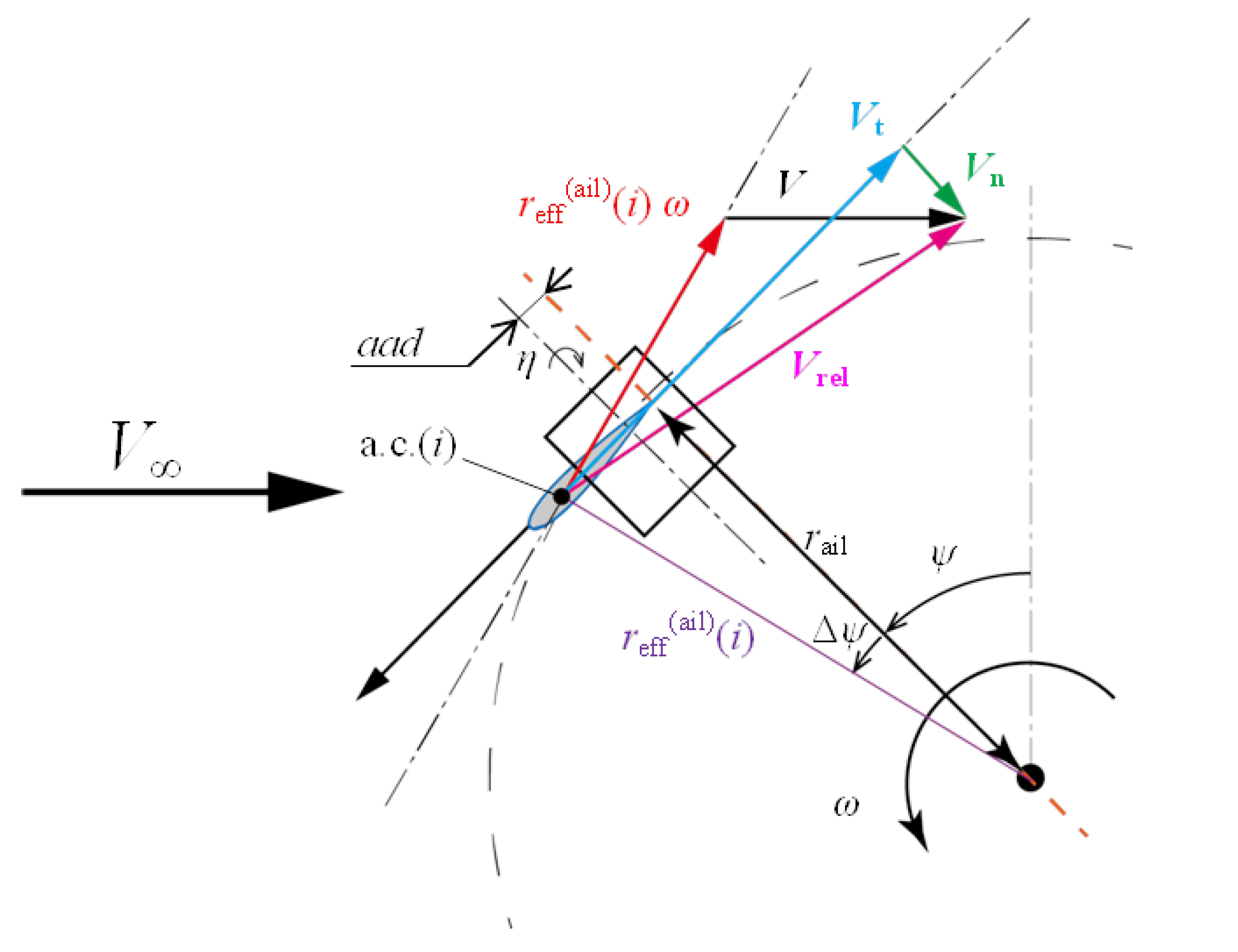
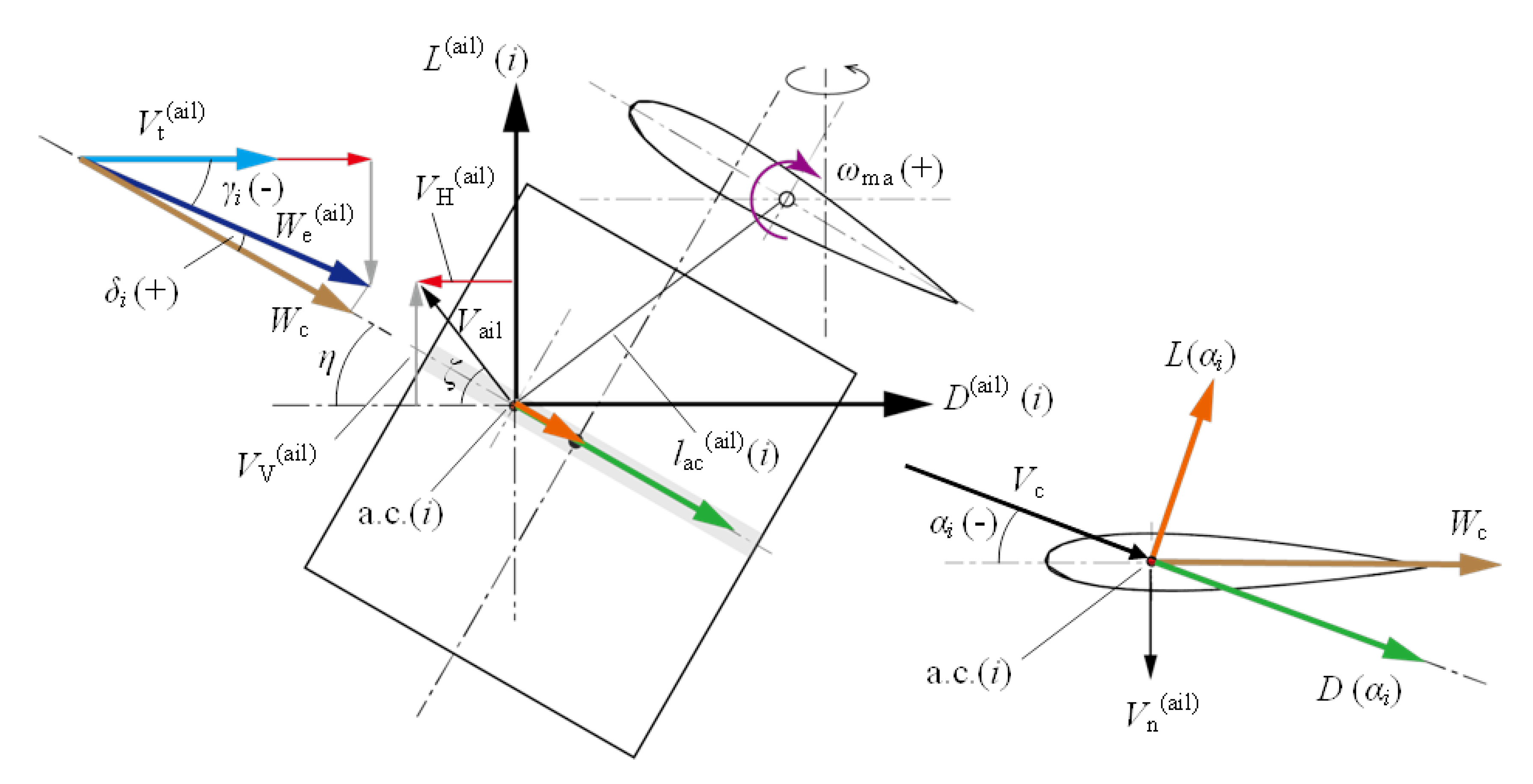
The appendix A presents the derivation of formula of lift and drag forces of aileron. Figure A1 presents a schematic showing the relative wind speed Vrel seen by the aerodynamic center (a.c.) of section i when the aileron is at azimuth Ψ and tilted at angle η. Figure A2 presents a schematic side view of the aileron in this case, and the right inset presents a cross-section of section i of the aileron. In Appendix A, assuming that an aileron is rotating clockwise in Figure A2 around a movable arm axis and that the relative wind seen by the aileron is a headwind, the formula of the lift force L(αi), drag force D(αi), and angle of attack αi are derived.
The radial distance reff(ail)(i) from the rotor rotational axis to the aerodynamic center of section i is expressed by Equation (29).
r e f f a i l i = r a i l 2 + a a d + l a c a i l i sin ζ i 2
The azimuth difference ΔΨ(i) created by the reference radius rail of the aileron and the radius reff(ail)(i) of section i is given by Equation (30).
ψ i = cos 1 r a i l r e f f a i l i
The tangential component Vt(ail) and normal component Vn(ail) of the relative wind speed Vrel are expressed by Equations (31) and (32), respectively.
V t a i l = cos ψ V + r e f f a i l i ω cos ψ + ψ i + sin ψ   r e f f a i l i ω sin ψ + ψ i
V n a i l = sin ψ V + r e f f a i l i ω cos ψ + ψ i cos ψ   r e f f a i l i ω sin ψ + ψ i
Here, V is the outer-rotor intersectional wind speed (Vu_out or Vd_out) at the hub height. The value of Vt(ail) is defined as positive when the direction is opposite to the rotational direction of the rotor, and the value of Vn(ail) is defined as positive when facing the rotational axis. As demonstrated in Figure A2, the aerodynamic center of aileron section i rotates around the movable arm axis at circumferential speed Vail.
V a i l = l a c a i l i ω m a
The horizontal component, VH(ail) and vertical component, VV(ail) of this circumferential velocity are given by Equations (34) and (35), respectively.
V H a i l = V a i l cos ζ   = l a c a i l i ω m a cos ζ
V V a i l = V a i l sin ζ   = l a c a i l i ω m a sin ζ
Here, VH(ail) is defined as positive when it is in the direction opposite to the rotational direction of the rotor, and VV(ail) is defined as positive when it is vertically upward. The tangential components Vt(ail) in Equation (31) is modified using the velocity components of the circumferential velocity Vail of the aileron to become the velocity component We(ail), which is calculated with Equation (36).
W e a i l = V t a i l + V H a i l   2 + V V a i l 2
In this case, the angle γi formed by Vt(ail) and We(ail) is obtained with Equation (37).
γ i = sin 1 V V a i l W   e a i l
When looking at We(ail) from Vt(ail), the angle γi is defined as a positive value in the counterclockwise direction. Therefore, in the case of Figure A2, the value of angle γi is negative. In this case, if the angle formed by the velocity component We(ail) and the chord line of the aileron section i is defined as δi, it can be determined by Equation (38).
δ i = η + γ i
Using angle δi, the velocity component Wc of the velocity We(ail) projected to the chord direction of the aileron section i is given by Equation (39).
W c = W e a i l cos δ i
When velocity component Wc and normal velocity component Vn(ail) in Equation (32) are combined, the relative wind speed Vc parallel to the cross-section of aileron section i is given by Equation (40).
V c = W c 2 + V n a i l 2
The angle of attack αi defined in the cross-section of the aileron section i is expressed by Equation (41).
α i = sin 1 V n a i l V c
However, in the assumed state here, 0° ≤ η ≤ 90° and Wc > 0, the value of the angle of attack αi is defined as positive when Vn(ail) < 0.
Because the angle of attack αi and the Reynolds number Re that is based on the c and Vc are determined, the lift coefficient CL(αi, Re) and the drag coefficient CD(αi, Re) are calculated by linear interpolation using the input airfoil aerodynamic data. Adopting the interpolated aerodynamic coefficients, the lift force L(αi) and drag force D(αi) acting on the cross-section of aileron section i can be calculated as follows:
L α i = 1 2 ρ V c 2 C L α i ,     R e c h i
D α i = 1 2 ρ V c 2 C D α i ,   R e c h i
where ρ is the air density, and Δhi is the width of aileron section i.
Figure A1. Schematic of relative wind velocities that i-th section of aileron encounters when it is under condition of azimuth Ψ with slant angle of η.
Preprints 105434 g0a1
Figure A2. Schematic of correction of velocity component Vt(ail) by considering self-rotation movement of aileron and derivation of aerodynamic force components.
Preprints 105434 g0a2

Appendix B

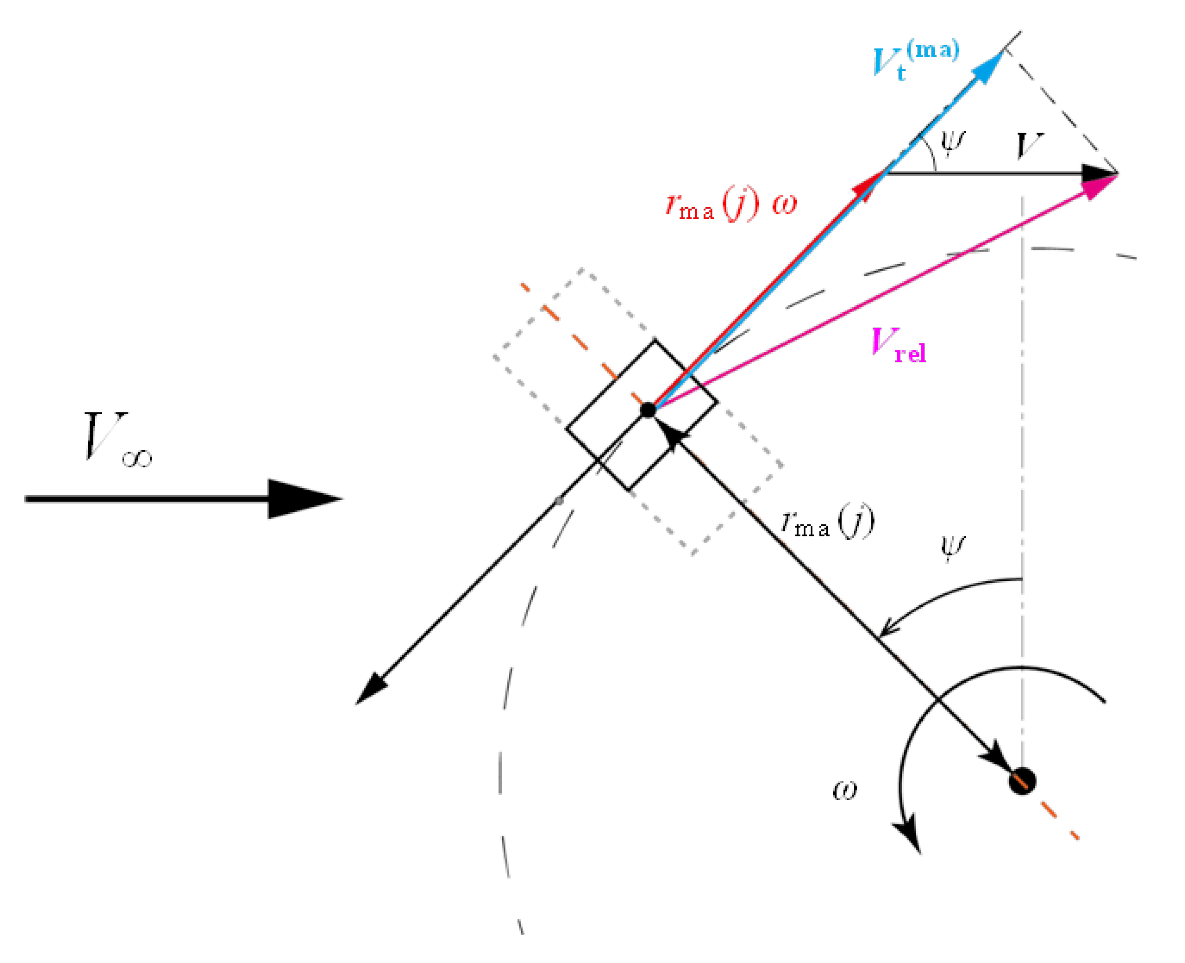
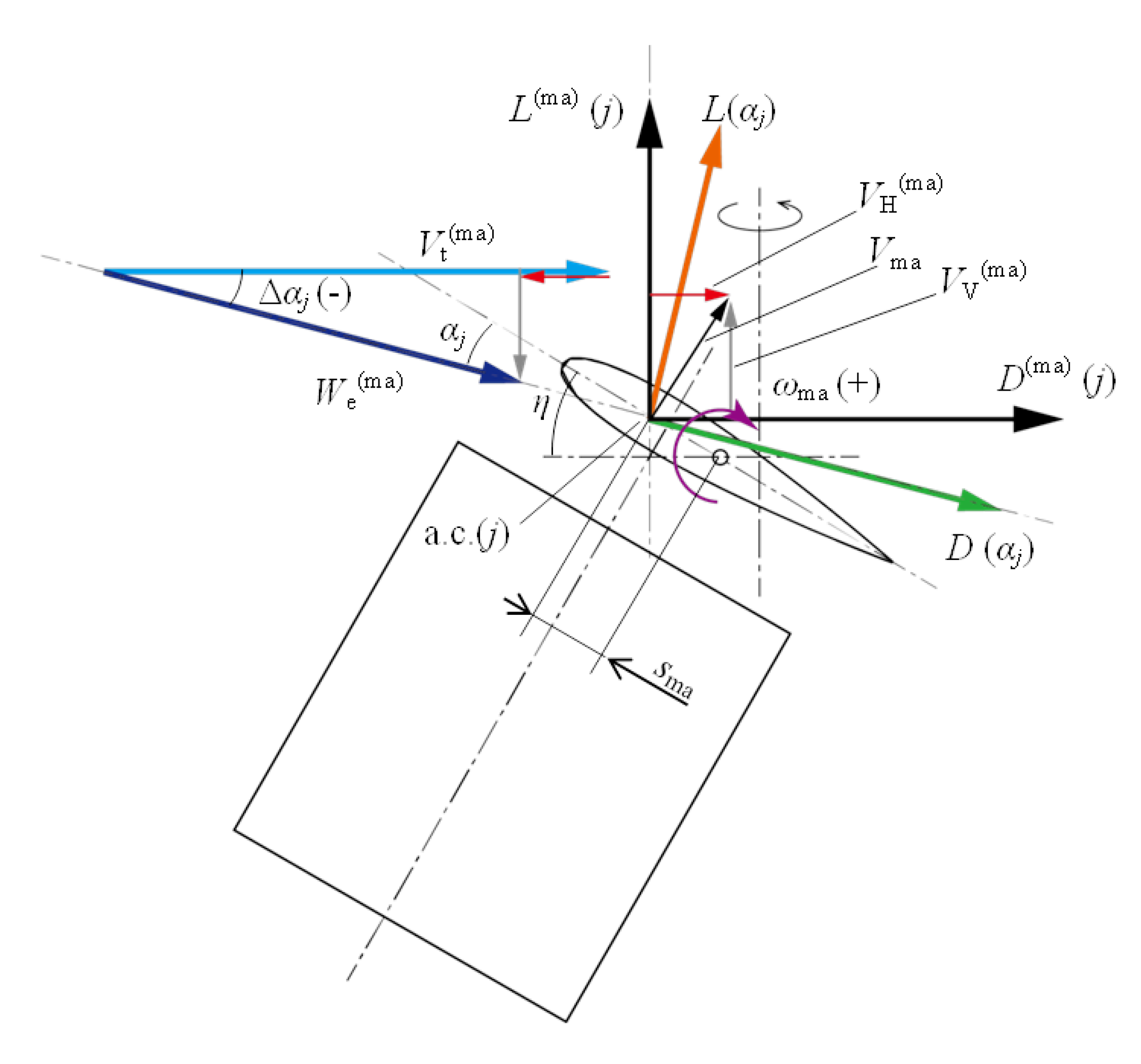
The appendix B presents the derivation of formula of lift and drag forces of movable arm. Figure A3 presents a schematic of the relative wind speed Vrel seen by section j when the movable arm is at azimuth Ψ and tilted at angle η. Figure A4 presents a schematic of the movable arm in this case. In this appendix, assuming that a movable arm is rotating clockwise in Figure A4 around its rotation axis and that the relative wind seen by the movable arm is a headwind, the formulas of the lift force L(αj), drag force D(αj), and angle of attack αj are derived.
In the case of the aileron in Figure A1, the azimuth difference ΔΨ(i) was considered. However, because the azimuth difference between the aerodynamic center of the movable arm and the reference position is small, the relative wind speed observed at the reference radius rma(j) is assumed to be the same as that observed at the aerodynamic center of the movable arm, as illustrated in Figure A3. In this case, the tangential component Vt(ma) of relative wind speed Vrel is expressed by Equation (44).
V t m a = V cos ψ + r m a j ω
Here, V is the outer-rotor intersectional wind speed (Vu_out or Vd_out) at the hub height. The value of Vt(ma) is defined as positive when the direction is opposite the rotational direction of the rotor. As illustrated in Figure A4, the aerodynamic center of the movable arm section j rotates around the movable arm axis at circumferential speed Vma.
V m a = s m a ω m a
where sma is the distance from the movable arm axis to the aerodynamic center. The horizontal component VH(ma) and vertical component VV(ma) of circumferential velocity Vma are given by Equations (46) and (47).
V H m a = V m a sin η = s m a ω m a sin η
V V m a = V m a cos η = s m a ω m a cos η
Here, VH(ma) is positive when it is in the direction opposite to the rotational direction of the rotor, and VV(ma) is positive when it is vertically upward. The tangential component, Vt(ma) in Equation (44), is modified with the velocity components of the circumferential velocity Vma of the movable arm to become the velocity component We(ma), calculated with Equation (48).
W e m a = V t m a V H m a   2 + V V m a 2
In this case, the angle Δαj formed by Vt(ma) and We(ma) is obtained by Equation (49).
α j = sin 1 V V m a W   e m a
When looking at We(ma) from Vt(ma), the angle Δαj is defined as a positive value in the counterclockwise direction. Therefore, in the case of Figure A4, the value of angle Δαj is negative. In this case, the angle of attack αj formed by the velocity component We(ma) and the chord line of the movable arm section j can be determined by Equation (50).
α j = η + α j
Because the angle of attack αj and the Reynolds number Re that is based on the c and We(ma) are determined, the lift coefficient CL(αj, Re) and the drag coefficient CD(αj, Re) are calculated by linear interpolation using the input airfoil aerodynamic data. Using the interpolated aerodynamic coefficients, the lift force L(αj) and drag force D(αj) acting on the cross-section of movable arm section j can be calculated as follows:
L α j = 1 2 ρ W e m a 2 C L α j ,   R e c r j
D α j = 1 2 ρ W e m a 2 C D α j ,   R e c r j
where Δrj is the width of the movable arm section j.
Figure A3. Schematic of relative wind velocities that j-th section of movable arm encounters when it is under condition of azimuth Ψ with slant angle of η. Difference between aerodynamic center position and reference position of movable arm is ignored because it is small.
Preprints 105434 g0a3
Figure A4. Schematic of correction of velocity component Vt(ma) by considering self-rotation movement of movable arm and the derivation of aerodynamic force components.
Preprints 105434 g0a4

References

  1. Cheng, C.; Blakers, A.; Stocks, M.; Lu, B. 100% renewable energy in Japan. Energy Conversion and Management 2022, 255, 115299. [Google Scholar] [CrossRef]
  2. Motohashi, H.; Goto, M.; Tan, S. Development of over speed protector for small scale wind turbines, In Proceedings of the 26th Wind Energy Utilization Symposium, Tokyo, Japan, 26 Nov. 2004; pp. 413-416. [https://www.jstage.jst.go.jp/article/jweasympo1979/26/0/26_0_413/_pdf].
  3. Noda, M.; Nagao, F.; Shinomiya, A. Aerodynamic autonomous control of gyromill wind turbine, In Proceedings of the Annual Meeting of Japan Association for Wind Engineering, 30 April 2007; pp. 255-256. [https://www.jstage.jst.go.jp/article/jaweam/2007/0/2007_0_79/_article/-char/ja/].
  4. Noda, M.; Nagao, F.; Shinomiya, A.; Muneta, K. Rotation control of straight wing vertical axis wind turbine with inhibition mechanism of overspeed rotation, In Proceedings of the 20th National Symposium on Wind Engineering, 2008; pp. 133-138. [https://www.jstage.jst.go.jp/article/kazekosymp/20/0/20_0_23/_pdf].
  5. Kiwata, T.; Yamada, T.; Kita, T.; Takata, S.; Komatsu, N.; Kimura, S. Performance of a Vertical Axis Wind Turbine with Variable-Pitch Straight Blades utilizing a Linkage Mechanism. Journal of Environment and Engineering 2010, 5, 1, pp. 213-225. https://doi.org/10.1299/jee.5.213. [CrossRef]
  6. Yamada, T.; Kiwata, T.; Kita, T.; Hirai, M.; Komatsu, N.; Kono, T. Overspeed Control of a Variable-Pitch Vertical-Axis Wind Turbine by Means of Tail Vanes. Journal of Environment and Engineering 2012, 7, 1, pp. 39-52. [CrossRef]
  7. Tanzawa, Y.; Shimizu, S.; Inoue, Y.; Shimizu, Y. Study on the aerodynamic brake of small gyro-mill type vertical axis wind turbine (1st report, method of the rotational speed continuous control under the strong wind). Transactions of the Japan Society of Mechanical Engineers Part B 2013, 79, 797, pp. 12-21. [CrossRef]
  8. Hara, Y.; Tagawa, K.; Saito, S.; Shioya, K.; Ono, T.; Makino, K.; Toba, K.; Hirobayashi, T.; Tanaka, Y.; Takashima, K.; Sasaki, S.; Nojima, K.; Yoshida, S. Development of a Butterfly Wind Turbine with Mechanical Over-Speed Control System. Designs 2018, 2, 2. [CrossRef]
  9. Hara, Y.; Saito, S.; Park, O.; Ishikawa, H.; Ono, T.; Higami, H. Behavior analysis of 7m Butterfly Wind Turbine with over-speed control using movable arms, In Proceedings of the 26th National Symposium on Power and Energy Systems, Saga, Japan, 13-14 July 2022; C213.
  10. Ando, H.; Hara, Y.; Miura, T.; Yoshida, S. The selection of blade cross section of a vertical axis wind turbine with a diameter of 14 m and the evaluation of rotor performance, In Proceedings of the 50th Student Graduation Research Presentation Conference of the Japan Society of Mechanical Engineering Chugoku-Shikoku Branch, Hiroshima University, 5 March 2020; 04a1 [https://repository.lib.tottori-u.ac.jp/records/2000017].
  11. Paraschivoiu, I. Wind turbine design: with emphasis on Darrieus concept. Polytechnic International Press: 2002; pp. 147-264.
  12. Hara, Y.; Kawamura, T.; Akimoto, H.; Tanaka, K.; Nakamura, T.; Mizumukai, K. Predicting Double-Blade Vertical Axis Wind Turbine Performance by a Quadruple-Multiple Streamtube Model. International Journal of Fluid Machinery and Systems 2014, 7, 1, pp. 16-27. [CrossRef]
  13. Sheldahl, R. E.; Klimas, P. C. Aerodynamic characteristics of seven symmetrical airfoil sections through 180-degree angle of attack for use in aerodynamic analysis of vertical axis wind turbines; Sandia National Laboratories: 1981; 6548367 [https://www.osti.gov/biblio/6548367]. [CrossRef]
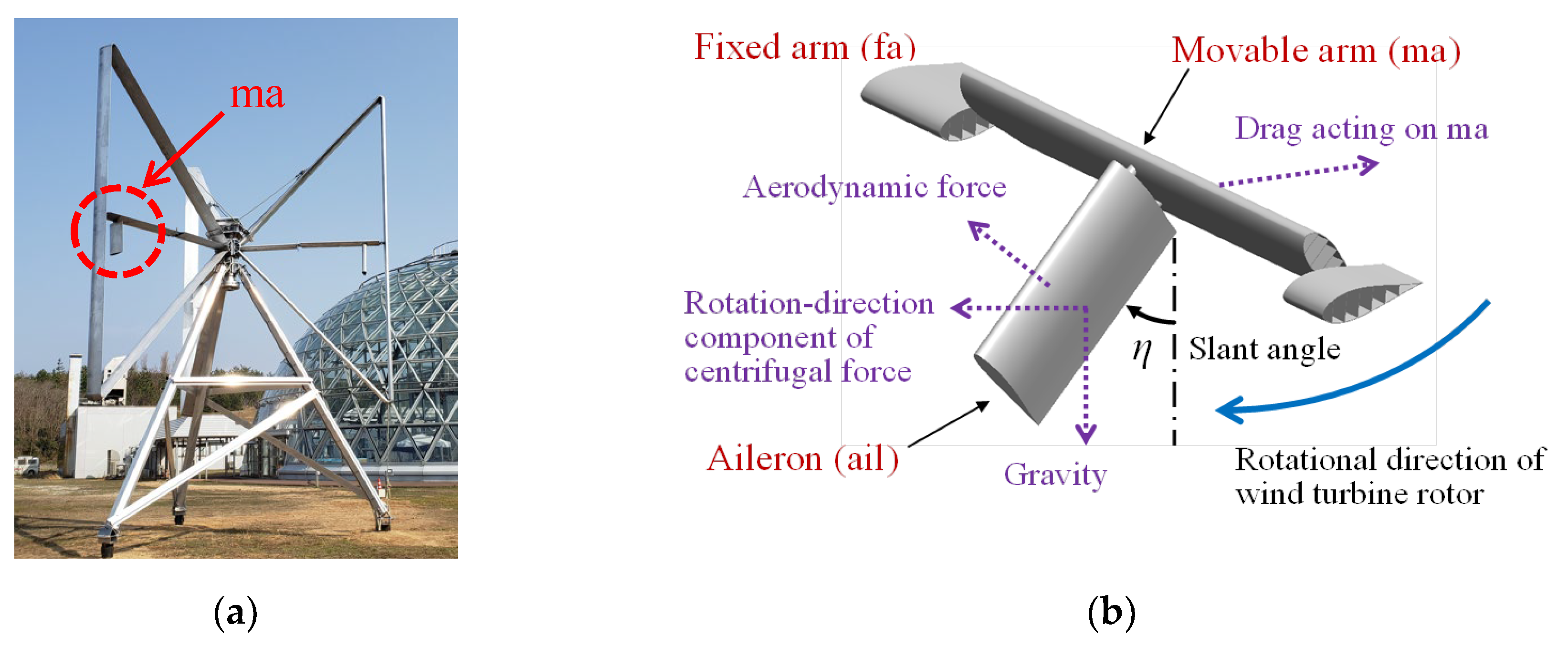
Figure 1. (a) Photo of prototype of butterfly wind turbine with diameter of 6.92 m and three looped blades; (b) Schematic of a movable arm with an aileron as over-speed control system, which works as aerodynamic brake when rotor rotational speed is high or wind speed is strong.
Preprints 105434 g001
Figure 2. Schematic illustrating main size of prototype of butterfly wind turbine, coordinate, vertical distribution of wind speed used in analytical prediction of turbine performance here.
Preprints 105434 g002
Figure 3. Schematic of horizontal arm including movable arm and aileron. Cross-section of vertical blade is depicted in red in this figure. Blue arrow depicts centrifugal force acting on section (i) of aileron when it is inclined.
Preprints 105434 g003
Figure 4. Schematic of movable arm and aileron inclined at slant angle η. Cross-section of fixed arm is shown in light brown. Rotational axis of movable arm is horizontally shifted by aad (axis-axis-distance) from rotational axis of wind turbine rotor.
Preprints 105434 g004
Figure 5. (a) Schematic of installation position of dampers; (b) Graph illustrating rotational angular velocity dependence of total resistance moment of six dampers installed in one movable arm.
Preprints 105434 g005
Figure 6. Schematic of quadruple-multiple streamtube (QMS) model [12]. In analysis, azimuth angle Ψ is defined as rotor revolves counterclockwise; origin is set at 90° from the most upstream direction. However, origin of integer parameter I is defined at opposite side of that of Ψ.
Preprints 105434 g006
Figure 7. Flow speed distributions predicted in two vertical levels (a) W = 5 and (b) W = 10 under condition of V = 6 m/s, N = 70 rpm, λ = 4.224. Black symbol depicts flow speed at outer rotor in upwind side, red symbol depicts that at outer rotor in downwind side, blue symbol depicts that at inner rotor in upwind side, and green symbol depicts that at inner rotor in downwind side. Analytical prediction of movement of movable arm assumed flow speed at outer rotor in equator level (W = 10) as flow speed which movable arm and aileron encounter.
Preprints 105434 g007
Figure 8. Flowchart of prediction of rotor performance (force, torque, and power) of butterfly wind turbine including behavior of movable arms. Prediction calculation assumes stationarity. However, in this flowchart, integer parameters I and n indicate azimuth and virtual rotor revolution number in calculation to obtain converged state.
Preprints 105434 g008
Figure 9. Prediction of variations in slant angle of movable arm in cases with and without dampers under condition of V = 6 m/s, N = 70 rpm, λ = 4.224, and span(ail) = 600 mm. Horizontal axis of this figure depicts accumulated azimuth angle until 16 virtual rotor revolutions at which convergence of slant angle was obtained for case with dampers. However, behavior of movable arm in case without dampers did not reach the convergence even at 30 rotor revolutions in this condition.
Preprints 105434 g009
Figure 10. Prediction of power coefficient of prototype of butterfly wind turbine equipped with movable arms with dampers. Span length of aileron span(ail) is assumed to be 600 mm in this prediction.
Preprints 105434 g010
Figure 11. Schematic of measurement system in field experiments of prototype. Data of tilt sensor installed in movable arm are transmitted by radio wave to receiver. Signal generated by photoelectric pulse generator was used to measure azimuth angle and rotor rotational speed.
Preprints 105434 g011
Figure 12. Representative experimental data of slant angle of movable arm, rotor rotational speed, and wind speed in case without dampers. Although decrease in rotor rotational speed was observed when movable arms inclined, simultaneously, violent movements of movable arms and noise generated by their impact on stoppers that limit slant angle range were observed.
Preprints 105434 g012
Figure 13. Representative experimental data of slant angle of movable arm, rotor rotational speed, and wind speed in case with dampers. Movements of movable arms became gentry and noise is gone by effects of dampers.
Preprints 105434 g013
Figure 14. Comparison of variation in slant angle of movable arm during one rotor revolution between cases with and without dampers. Horizontal axis is azimuth angle defined in Figure 6.
Preprints 105434 g014
Figure 15. Prediction of rotor torque of prototype equipped with movable arms without dampers. Span length of aileron span(ail) is assumed to be 600 mm in this prediction. Black solid line is control target (load torque) and intersections with rotor torque curves give expected operating states.
Preprints 105434 g015
Figure 16. Comparison of wind speed dependence of rotor rotational speed between prediction and experiment data, which was averaged for 20 s, in case without dampers and span(ail) of 600 mm.
Preprints 105434 g016
Figure 17. Prediction of rotor torque of prototype equipped with movable arms with dampers. Span length of aileron span(ail) is assumed to be 600 mm in this prediction. Black solid line is control target (load torque) and intersections with rotor torque curves give expected operating states.
Preprints 105434 g017
Figure 18. Comparison of wind speed dependence of rotor rotational speed between prediction and experiment data, averaged for 20 s, in case with dampers and span(ail) of 600 mm.
Preprints 105434 g018
Figure 19. Prediction of rotor torque of prototype equipped with movable arms with dampers. Span length of aileron span(ail) is assumed to be 400 mm in this prediction. Black solid line is control target (load torque), and intersections with rotor torque curves give expected operating states.
Preprints 105434 g019
Figure 20. Comparison of wind speed dependence of rotor rotational speed between prediction and experiment data, which was averaged for 20 s, in case with dampers and span(ail) of 400 mm.
Preprints 105434 g020
Disclaimer/Publisher’s Note: The statements, opinions and data contained in all publications are solely those of the individual author(s) and contributor(s) and not of MDPI and/or the editor(s). MDPI and/or the editor(s) disclaim responsibility for any injury to people or property resulting from any ideas, methods, instructions or products referred to in the content.
Copyright: This open access article is published under a Creative Commons CC BY 4.0 license, which permit the free download, distribution, and reuse, provided that the author and preprint are cited in any reuse.
Prerpints.org logo

Preprints.org is a free preprint server supported by MDPI in Basel, Switzerland.

Subscribe

© 2024 MDPI (Basel, Switzerland) unless otherwise stated