Submitted:
06 May 2024
Posted:
08 May 2024
You are already at the latest version
Abstract
Keywords:
1. Introduction
- Improvement of fossil fuel-based energy efficiency;
- Enhancement of nuclear and renewable energy as well as increasing use of biofuel-based energy;
- Development of environmental engineering works such as afforestation and reforestation.
- CCUS can be easily integrated into existing energy and utility systems, without invasive or complex retrofits;
- CCUS can be implemented for the production of low-carbon hydrogen (blue hydrogen): currently, around 76% of hydrogen (corresponding to 75 Mt y–1) is produced worldwide from natural gas, generating overall CO2 emissions exceeding 800 Mt y–1 [8]; green hydrogen produced by electrolysis is still expensive having a cost of 2.3–6.9 $ tH2–1 versus 1.4–2.4 $ tH2–1 from steam methane reforming (SMR) coupled with CCS [8,9];
- The technology features extremely high selectivity, and thus minimizes the competitive capture of other components in the flue gases;
- The separation process is driven by temperature differences and does not rely on solvents, adsorbents or membranes;
- The CO2 product is generally extracted in the liquid phase, so as to avoid the downstream compression work;
- Scalability potential and wide ranges of applications have been demonstrated. In addition, CCC can be integrated into existing industrial processes with minimal retrofit requirements;
- CCC is characterized by low water consumption and offers a large heat integration potential. This, in turn, minimizes the disposal of wastes and enhances safety and environmental aspects.
2. Fundamentals of Cryogenic Desublimation
3. Processes Based on Cryogenic Desublimation
3.1. Dynamic Packed Bed
3.2. External Cooling Loop
3.3. Stirling Cooler
3.4. Antisublimation (AnSU)
3.5. Novel Low-Cost CO2 Capture Technology (NLCCT)
3.6. Comparison of Cryogenic Desublimation Processes
4. Conclusions and Future Directions
- The operating conditions of CCC, including temperature ranges, pressure levels, and heat integration potential need to be further optimized. Understanding the influence of these process variables on the separation efficiency as well as the energy consumption is pivotal for scale-up and commercialization purposes.
- Assessing the economic viability of CCC and identifying strategies to reduce costs are critical knowledge gaps. Research should focus on the development of cost-effective materials and innovative engineering solutions at cryogenic conditions to enhance the overall economic feasibility. This should include insulation materials, equipment materials, and additional materials for constructing heat exchangers.
- Understanding how CCC can be effectively integrated into various industrial processes is another key research aspect. This encompasses the retrofit of CCC with various industries, identifying potential synergies and addressing engineering challenges.
- Investigating the safety aspects and potential risks associated with CCC is paramount. Research needs to be carried out on the behavior of cryogenic fluids, their associated hazards and the development of robust safety protocols to ensure the protection of personnel and the environment.
- A comprehensive assessment of the environmental impact of CCC is necessary. This should involve evaluating the overall carbon footprint of the technology, including indirect emissions associated with equipment production, transportation, and other life cycle stages.
Author Contributions
Funding
Data Availability Statement
Conflicts of Interest
Nomenclature
| Acronyms | ||
| AnSU | Antisublimation | |
| BECCS | Bioenergy with carbon capture and storage | |
| CCC | Cryogenic carbon capture | |
| CCS | Carbon capture and storage | |
| CCU | Carbon capture and utilization | |
| CCUS | Carbon capture, utilization and storage | |
| COP | Coefficient of performance | |
| DAC | Direct air capture | |
| EoS | Equation of state | |
| NLCCT | Novel low-cost CO2 capture technology | |
| PSA | Pressure swing adsorption | |
| RIC | Refrigeration integrated cascade | |
| SMR | Steam methane reforming | |
| SVE | Solid-vapor equilibrium | |
| SLVE | Solid-liquid-vapor equilibrium | |
| TRL | Technology readiness level | |
| TSA | Temperature swing adsorption | |
| Symbols | Unit | Description |
| Pa m6 mol–2 | Energy parameter in cubic EoS | |
| m3 mol–1 | Covolume in cubic EoS | |
| W m−2 K−1 | Heat transfer coefficient of the gas phase | |
| W m−2 K−1 | Heat transfer coefficient of the liquid phase | |
| kg m–2 s−1 | Mass transfer coefficient of the gas phase | |
| mol | Moles of CO2 in the feed | |
| mol | Moles of CO2 in the product 1 | |
| mol | Moles of CO2 in the product 2 | |
| mol | Moles of inert in the feed | |
| mol | Moles of inert in the product 1 | |
| mol | Moles of inert in the product 2 | |
| Pa | Total pressure | |
| Pa | Sublimation vapor pressure of CO2 | |
| Pa | Initial pressure of compression | |
| Pa | Final pressure of compression | |
| W | Thermal duty of condensation | |
| kJ kg-1 | Specific thermal duty of separation | |
| W m−2 | Sensible heat flux of the gas phase | |
| W m−2 | Latent heat flux of the gas phase | |
| W m−2 | Sensible heat flux of the liquid phase | |
| J mol−1 K−1 | Ideal gas constant | |
| m2 | Interface surface | |
| K | Temperature | |
| K | Ambient temperature | |
| K | Temperature of liquefaction | |
| K | Temperature of the gas phase | |
| K | Temperature of the interphase | |
| K | Temperature of the liquid phase | |
| K | Temperature of the hot source used for separation | |
| m3 mol–1 | Molar volume in cubic EoS | |
| m3 mol–1 | Molar volume of solid CO2 | |
| kJ kgCO2–1 | Minimum work rate of compression | |
| kJ kgCO2–1 | Actual work of compression | |
| kJ kgCO2–1 | Minimum work of liquefaction | |
| kJ kgCO2–1 | Actual work of liquefaction | |
| kJ kgCO2–1 | Minimum work of separation | |
| kJ kgCO2–1 | Actual work of separation | |
| – | Mole fraction of CO2 in the vapor phase | |
| – | Mole fraction of CO2 in the interface | |
| – | Mole fraction of CO2 in the feed | |
| – | Mole fraction of CO2 in the product 1 | |
| – | Mole fraction of CO2 in the product 2 | |
| – | Mole fraction of inert in the feed | |
| – | Mole fraction of inert in the product 1 | |
| – | Mole fraction of inert in the product 2 | |
| m | Axial dimension | |
| Greek letters | ||
| – | II law efficiency | |
| J kg–1 | Heat of liquefaction of CO2 | |
| – | Fugacity coefficient of CO2 at the saturated solid pressure | |
| – | Fugacity coefficient of CO2 in the vapor phase | |
References
- IPCC, 2021: Summary for Policymakers. In: Climate Change 2021: The Physical Science Basis. Contribution of Working Group I to the Sixth Assessment Report of the Intergovernmental Panel on Climate Change [Masson-Delmotte, V.; P. Zhai, A. Pirani, S.L. Connors, C. Péan, S. Berger, N. Caud, Y. Chen, L. Goldfarb, M.I. Gomis, M. Huang, K. Leitzell, E. Lonnoy, J.B.R. Matthews, T.K. Maycock, T. Waterfield, O. Yelekçi, R. Yu, and B. Zhou (eds.)]. Cambridge University Press, Cambridge, United Kingdom and New York, NY, USA, pp. 3−32.
- Gabrielli, P.; Gazzani, M.; Mazzotti, M. The role of carbon capture and utilization, carbon capture and storage, and biomass to enable a net-zero-CO2 emissions chemical industry. Industrial and Engineering Chemistry Research 2020, 59, 7033–7045. [Google Scholar] [CrossRef]
- Keyßer, L.T.; Lenzen, M. 1.5 °C degrowth scenarios suggest the need for new mitigation pathways. Nat Commun 2021, 12, 2676. [Google Scholar] [CrossRef] [PubMed]
- Bednar, J.; Obersteiner, M.; Baklanov, A.; Thomson, M.; Wagner, F.; Geden, O.; Allen, M.; Hall, J.W.A.; et al. Operationalizing the net-negative carbon economy. Nature 2021, 596, 377–383. [Google Scholar] [CrossRef] [PubMed]
- IEA. Energy Technology Perspectives, 2020. IEA, Paris https://www.iea.org/reports/energy-technology-perspectives-2020, Licence: CC BY 4.0.
- Schmitt, T.; Homsy, S.; Mantripragada, H.; Woods, M.; Hoffman, H.; Shultz, T.; Fout, T.; Hackett, G. Cost and Performance of Retrofitting NGCC Units for Carbon Capture: U.S. Department of Energy Office of Scientific and Technical Information, 2023.
- Capocelli, M.; Luberti, M.; Inno, S.; D’Antonio, F.; Di Natale, F.; Lancia, A. Post-combustion CO2 capture by RVPSA in a large-scale steam reforming plant. Journal of CO2 Utilization 2019, 32, 53–65. [Google Scholar] [CrossRef]
- Luberti, M.; Brown, A.; Balsamo, M.; Capocelli, M. Numerical analysis of VPSA technology retrofitted to steam reforming hydrogen plants to capture CO2 and produce blue H2. Energies 2022, 15, 1091. [Google Scholar] [CrossRef]
- Luberti, M.; Ahn, H. Review of Polybed pressure swing adsorption for hydrogen purification. International Journal of Hydrogen Energy 2022, 47, 10911–10933. [Google Scholar] [CrossRef]
- Barba, D.; Brandani, F.; Capocelli, M.; Luberti, M.; Zizza, A. Process analysis of an industrial waste-to-energyplant: Theory and experiments. Process Safety and Environmental Protection 2015, 96, 61–73. [Google Scholar] [CrossRef]
- Butnar, I; Cronin, J.; Pye, S.; Review of Carbon Capture Utilisation and Carbon Capture and Storage in future EU decarbonisation scenarios, 2020. Final report prepared for The Carbon Capture and Storage Association - UCL Energy Institute.
- Koeble, B.S.; van den Broek, M.A.; Faaij, A.P.C.; van Vuuren et al, D.P. Uncertainty in Carbon Capture and Storage (CCS) deployment projections: a cross-model comparison exercise. Climatic Change 2014, 123, 461–476. [Google Scholar]
- Capocelli, M.; De Falco, M. Generalized penalties and standard efficiencies of carbon capture and storage processes. International Journal of Energy Research 2022, 46, 4808–4824. [Google Scholar] [CrossRef]
- Sifat, N.S.; Yousef, H. A critical review of CO2 capture technologies and prospects for clean power generation. Energies 2019, 12, 4143. [Google Scholar] [CrossRef]
- Kearns, D.; Liu, H.; Consoli, C. Technology Readiness and Costs of CCS. Global CCS Institute, 2021.
- Ahn, H.; Luberti, M.; Liu, Z.; Brandani, S. Process simulation of aqueous MEA plants for post-combustion capture from coal-fired power plants. Energy Procedia 2013, 37, 1523–1531. [Google Scholar] [CrossRef]
- Erto, A.; Silvestre-Albero, A.; Silvestre-Albero, J.; Rodríguez-Reinoso, F.; Balsamo, M.; Lancia, A.; Montagnaro, F. Carbon-supported ionic liquids as innovative adsorbents for CO₂ separation from synthetic flue-gas. J Colloid Interface Sci. 2015, 15, 41–50. [Google Scholar] [CrossRef] [PubMed]
- Luberti, M.; Oreggioni, G.D.; Ahn, H. Design of a rapid vacuum pressure swing adsorption (RVPSA) process for post-combustion CO2 capture from a biomass-fuelled CHP plant. Journal of Environmental Chemical Engineering 2017, 5, 3973–3982. [Google Scholar] [CrossRef]
- Luberti, M.; Ahn, H. Design of an industrial multi-bed (V)PSA unit for argon concentration. Separation and Purification Technology 2021, 261, 118254. [Google Scholar] [CrossRef]
- Brunetti, A.; Scura, F.; Barbieri, G.; Drioli, E. Membrane technologies for CO2 separation. Journal of Membrane Science 2010, 359, 115–125. [Google Scholar] [CrossRef]
- Font-Palma, C.; Cann, D.; Udemu, C. Review of cryogenic carbon capture innovations and their potential applications. Journal of Carbon Research 2021, 7, 58. [Google Scholar] [CrossRef]
- Swanson, C.E.; Elzey, J.W.; Hershberger, R.E.; Donnelly, R.J.; Pfotenhauer, J. Thermodynamic analysis of low-temperature carbon dioxide and sulfur dioxide capture from coal-burning power plants. Physical Review E 2012, 86, 016103. [Google Scholar] [CrossRef] [PubMed]
- S. Holmes and J. M. Ryan, Cryogenic distillative separation of acid gases from methane, US Patent 4,318,723, 1982.
- Hart, A.; Gnanendran, N. Cryogenic CO2 capture in natural gas. Energy Procedia 2009, 1, 697–706. [Google Scholar] [CrossRef]
- Yousef, A.M.; El-Maghlany, W.M.; Eldrainy, Y.A.; Attia, A. New approach for biogas purification using cryogenic separation and distillation process for CO2 capture. Energy 2018, 156, 328–351. [Google Scholar] [CrossRef]
- Shen, M.; Tong, L.; Yin, S.; Liu, C.; Wang, L.; Feng, W.; Ding, Y. Cryogenic technology progress for CO2 capture under carbon neutrality goals: A review. Separation and Purification Technology 2022, 299, 121734. [Google Scholar] [CrossRef]
- Berstad, D.; Skaugen, G.; Roussanaly, S.; Anantharaman, R.; Nekså, P.; Jordal, K.; Trædal, S.; Gundersen, T. CO2 capture from IGCC by low-temperature synthesis gas separation. Energies 2022, 15, 515. [Google Scholar] [CrossRef]
- Eide, L.I.; Anheden, M.; Lyngfelt, A.; Abanades, C.; Younes, M.; Clodic, D.; Bill, A.A.; Feron, P.H.M.; Rojey, A.; Giroudiere, F. Novel capture processes. Oil and Gas Science and Technology 2005, 60, 497–508. [Google Scholar] [CrossRef]
- Tuinier, M.J.; van Sint Annaland, M.; Kramer, G.J.; Kuipers, J.A.M. Cryogenic CO2 capture using dynamically operated packed beds. Chemical Engineering Science 2010, 65, 114–119. [Google Scholar] [CrossRef]
- Jensen, M.J.; Russell, C.S.; Bergeson, D.; Hoeger, C.D.; Frankman, D.J.; Bence, C.S.; Baxter, L.L. Prediction and validation of external cooling loop cryogenic carbon capture (CCC-ECL) for full-scale coal-fired power plant retrofit. International Journal of Greenhouse Gas Control 2015, 45, 200–212. [Google Scholar] [CrossRef]
- Song, C.; Liu, Q.; Deng, S.; Li, H.; Kitamura, Y. Cryogenic-based CO2 capture technologies: State-of-the-art developments and current challenges. Renewable and Sustainable Energy Reviews 2019, 101, 265–278. [Google Scholar] [CrossRef]
- Asgharian, H.; Iov, F.; Araya, S.S.; Pedersen, T.H.; Nielsen, M.P.; Baniasadi, E.; Liso, V. A Review on process modeling and simulation of cryogenic carbon capture for post-combustion treatment. Energies 2023, 16, 1855. [Google Scholar] [CrossRef]
- Aneesh, A.M.; Sam, A.A. A mini-review on cryogenic carbon capture technology by desublimation: theoretical and modeling aspects. Frontiers in Energy Research 2023, 11, 1167099. [Google Scholar] [CrossRef]
- Yang, W.; Li, S.; Li, X.; Liang, Y.; Zhang, X. Analysis of a new liquefaction combined with desublimation system for CO2 separation based on N2/CO2 phase equilibrium. Energies 2015, 8, 9495–9508. [Google Scholar] [CrossRef]
- De Guido, G.; Langè, S.; Moioli, S.; Pellegrini, L.A. Thermodynamic method for the prediction of solid CO2 formation from multicomponent mixtures. Process Safety and Environmental Protection 2014, 92, 70–79. [Google Scholar] [CrossRef]
- De Guido, G.; Pellegrini, L.A. Phase equilibria analysis in the presence of solid carbon dioxide. Chemical Engineering Transactions 2021, 86. [Google Scholar]
- Wang, J.; Wang, Z.; Sun, B. Improved equation of CO2 Joule–Thomson coefficient. Journal of CO2 Utilization 2017, 19, 296–307. [Google Scholar] [CrossRef]
- Pellegrini, L.; De Guido, G.; Ingrosso, S. Thermodynamic Framework for Cryogenic Carbon Capture. Proceedings of the 30th European Symposium on Computer Aided Process Engineering 2020 (ESCAPE30), Milano, Italy.
- Jensen, M. Energy Process Enabled by Cryogenic Carbon Capture. Brigham Young University BYU Theses and Dissertations 2015, 5711. [Google Scholar]
- Baxter, L.; Baxter, A.; Burt, S. Cryogenic CO2 capture as a cost-effective CO2 capture process. International Pittsburgh Coal Conference, Pittsburgh, USA, 2009.
- Yurata, T.; Lei, H.; Tang, L.; Lu, M.; Patel, J.; Lim, S.; Piumsomboon, P.; Chalermsinsuwan, B.; Li, C. Feasibility and sustainability analyses of carbon dioxide – hydrogen separation via de-sublimation process in comparison with other processes. International Journal of Hydrogen Energy 2019, 44, 23120–23134. [Google Scholar] [CrossRef]
- Seader, J.D.; Henley, E. Separation Process Principles, 2006. John Wiley & Sons. Ing.
- Zonfrilli, M.; Facchino, M.; Serinelli, R.; Chesti, M.; De Falco, M.; Capocelli, M. Thermodynamic analysis of cold energy recovery from LNG regasification. Journal of Cleaner Production, 2023, 420, 138443. [Google Scholar] [CrossRef]
- House, K.Z.; Harvey, C.F.; Aziz, M.J.; Schrag, D.P. The Energy Penalty of Post-Combustion CO2 Capture & Storage and Its Implications for Retrofitting the U.S. Installed Base. Energy & Environmental Science 2009, 2, 193. [Google Scholar]
- Bejan, A. Advanced Engineering Thermodynamics. 4th ed. Hoboken, NJ: John Wiley & Sons, Inc.; 2016.
- Yu, Z.; Miller, F.; Pfotenhauer, J.M. Numerical modeling and analytical modeling of cryogenic carbon capture in a de-sublimating heat exchanger. IOP Conf. Series: Materials Science and Engineering 2017, 278, 012032. [Google Scholar] [CrossRef]
- Berger, A.H.; Hoeger, C.; Baxter, L.; Bhown, A.S. Evaluation of cryogenic systems for post combustion CO2 capture. 14th International Conference on Greenhouse Gas Control Technologies, GHGT-14, Melbourne, Australia, 2018.
- Cann, D.G. Experimental exploration of cryogenic CO2 capture utilising a moving bed Thesis submitted in accordance with the requirements of the University of Chester for the degree of Doctor of Philosophy, 2021.
- James, D.W. Failing Drop CO2 Deposition (Desublimation) Heat Exchanger for the Cryogenic Carbon Capture Process. Theses and Dissertations, 2011. Brigham Young University.
- Sun, B.; Ghatage, S.; Evans, G.M.; Bhatelia, T.; Utikar, R.P.; Pareek, V.K. Dynamic study of frost formation on cryogenic surface. International Journal of Heat and Mass Transfer 2020, 150, 119372. [Google Scholar] [CrossRef]
- Wu, X.; Ma, Q.; Chu, F.; Hu, S. Phase change mass transfer model for frost growth and densification. International Journal of Heat and Mass Transfer 2016, 96, 11–19. [Google Scholar] [CrossRef]
- Wu, X.M.; Webb, R.L. Investigation of the possibility of frost release from a cold surface. Experimental Thermal and Fluid Science 2001, 24, 151–156. [Google Scholar] [CrossRef]
- Lei, T.; Luo, K.H.; Hernández Pérez, F.E.; Wang, G.; Wang, Z.; Cano, J.R.; Im, H.G. Study of CO2 desublimation during cryogenic carbon capture using the lattice Boltzmann method. Journal of Fluid Mechanics 2023, 964, A1. [Google Scholar] [CrossRef]
- Pan, X.; Clodic, D.; Toubassy, J. CO2 capture by antisublimation process and its technical economic analysis. Greenhouse Gas Science and Technology 2013, 3, 8–20. [Google Scholar] [CrossRef]
- Rezaei, S.; Liu, A.; Hovington, P. Emerging technologies in post-combustion carbon dioxide capture & removal. Catalysis Today 2023, 423, 114286. [Google Scholar]
- Tuinier, M.J.; van Sint Annaland, M.; Kuipers, J.A.M. A novel process for cryogenic CO2 capture using dynamically operated packed beds—An experimental and numerical study. International Journal of Greenhouse Gas Control 2011, 5, 694–701. [Google Scholar] [CrossRef]
- Luberti, M. Oxygen recovery from ozone generators by adsorption processes. Adsorption 2023, 29, 73–86. [Google Scholar] [CrossRef]
- Tuinier, M.J.; Hamers, H.P.; van Sint Annaland, M. Techno-economic evaluation of cryogenic CO2 capture—A comparison with absorption and membrane technology. International Journal of Greenhouse Gas Control 2011, 5, 1559–1565. [Google Scholar] [CrossRef]
- Lively, R.P.; Koros, W.J.; Johnson, J.R. Enhanced cryogenic CO2 capture using dynamically operated low-cost fiber beds. Chemical Engineering Science 2012, 71, 97–103. [Google Scholar] [CrossRef]
- Willson, P.; Lychnos, G.; Clements, A.; Michailos, S.; Font-Palma, C.; Diego, M.E.; Pourkashanian, M.; Howe, J. Evaluation of the performance and economic viability of a novel low temperature carbon capture process. International Journal of Greenhouse Gas Control 2019, 86, 1–9. [Google Scholar] [CrossRef]
- Cann, D.; Font-Palma, C.; Willson, P. Experimental analysis of CO2 frost front behaviour in moving packed beds for cryogenic CO2 capture. International Journal of Greenhouse Gas Control 2021, 107, 103291. [Google Scholar] [CrossRef]
- Cann, D.; Font-Palma, C.; Willson, P. Moving packed beds for cryogenic CO2 capture: analysis of packing material and bed precooling. Carbon Capture Science & Technology 2021, 1, 100017. [Google Scholar]
- Cann, D.; Font-Palma, C. Evaluation of mathematical models for CO2 frost formation in a cryogenic moving bed. Energies 2023, 16, 2314. [Google Scholar] [CrossRef]
- Sayre, A.; Frankman, D.; Baxter, A.; Stitt, K. Field testing of cryogenic carbon capture. Carbon Management Technology Conference, Houston, USA, 2017.
- Baxter, L. Systems and methods for separating condensable vapors from light gases or liquids by recuperative cryogenic process. US Patent No. US 10,724,793 B2 to Hall Labs LLC, 2020.
- Safdarnejad, S.M.; Hedengren, J.D.; Baxter, L.L. Plant-level dynamic optimization of Cryogenic Carbon Capture with conventional and renewable power sources. Applied Energy 2015, 149, 354–366. [Google Scholar] [CrossRef]
- Baxter, L.L.; Baxter, A.; Bever, E.; Burt, S.; Chamberlain, S.; Frankman, D.; Hoeger, C.; Mansfield, E.; Parkinson, D.; Sayre, A.; Stitt, K. Cryogenic Carbon Capture Development. Final Technical Report submitted to US DoE NETL, 2019.
- Song, C.; Lu, J.; Kitamura, Y. Study on the COP of free piston Stirling cooler (FPSC) in the anti-sublimation CO2 capture process. Renewable Energy 2015, 74, 948–954. [Google Scholar] [CrossRef]
- Song, C.; Kitamura, Y.; Li, S.; Ogasawara, K. Design of a cryogenic CO2 capture system based on Stirling coolers. International Journal of Greenhouse Gas Control 2012, 7, 107–114. [Google Scholar] [CrossRef]
- Song, C.; Kitamura, Y.; Li, S.; Jiang, W. Parametric analysis of a novel cryogenic CO2 capture system based on Stirling coolers. Environmental Science and Technology 2012, 46, 12735–12741. [Google Scholar] [CrossRef] [PubMed]
- Song, C.; Kitamura, Y.; Li, S. Optimization of a novel cryogenic CO2 capture process by response surface methodology (RSM). Journal of the Taiwan Institute of Chemical Engineers 2014, 45, 1666–1676. [Google Scholar] [CrossRef]
- Song, C.; Kitamura, Y.; Li, S.; Lu, J. Deposition CO2 capture process using a free piston Stirling cooler. Industrial and Engineering Chemistry Research 2013, 52, 14936–14943. [Google Scholar] [CrossRef]
- Song, C.; Liu, Q.; Ji, N.; Deng, S.; Zhao, J.; Kitamura, Y. Advanced cryogenic CO2 capture process based on Stirling coolers by heat integration. Applied Thermal Engineering 2017, 114, 887–895. [Google Scholar] [CrossRef]
- Clodic, D.; Younes, M. A new method for CO2 capture: frosting CO2 at atmospheric pressure. Greenhouse Gas Control Technologies 2003, I. [Google Scholar]
- Clodic, D.; El Hitti, R.; Younes, M.; Bill, A.; Casier, F. CO2 capture by anti-sublimation: Thermo-economic process evaluation. 4th Annual Conference on Carbon Capture & Sequestration, Alexandria, USA, 2005.
- Clodic, D.; Younes, M. Method and system for extracting carbon dioxide by anti-sublimation for storage thereof. US Patent No. 7,073,348 B2 to Armines, 2006.
- Clodic, D.; Younes, M.; Bill, A. Test results of CO2 capture by anti-sublimation: Capture efficiency and energy consumption for boiler plants. Greenhouse Gas Control Technologies 2005, II. [Google Scholar]
- Hees, W.G.; Monroe, C.M. Method and system for extracting carbon dioxide by anti-sublimation at raised pressure. US Patent No. 8,163,070 B2 to Armines, 2012.
- De, D.K.; Oduniyi, I.A. Highly cost effective technology for capture of industrial emissions without reagent for clean energy and clean environment applications. US Patent No. 10,670,334 B2 to Sustainable Green Power Industries, 2020.
- De, D.K.; Oduniyi, I.A.; Sam, A.A. A novel cryogenic technology for low-cost carbon capture from NGCC power plants for climate change mitigation. Thermal Science and Engineering Progress 2022, 36, 101495. [Google Scholar] [CrossRef]
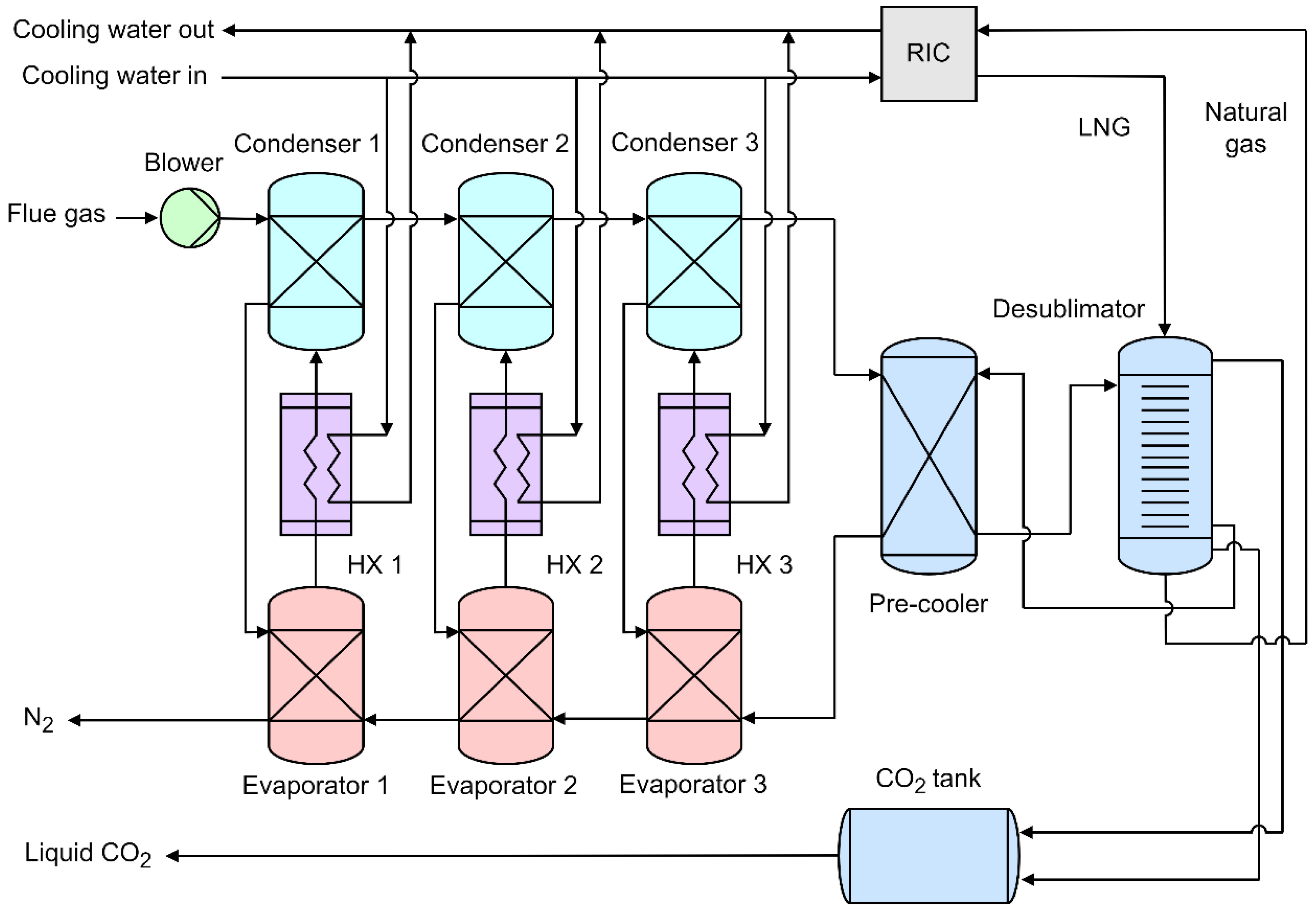
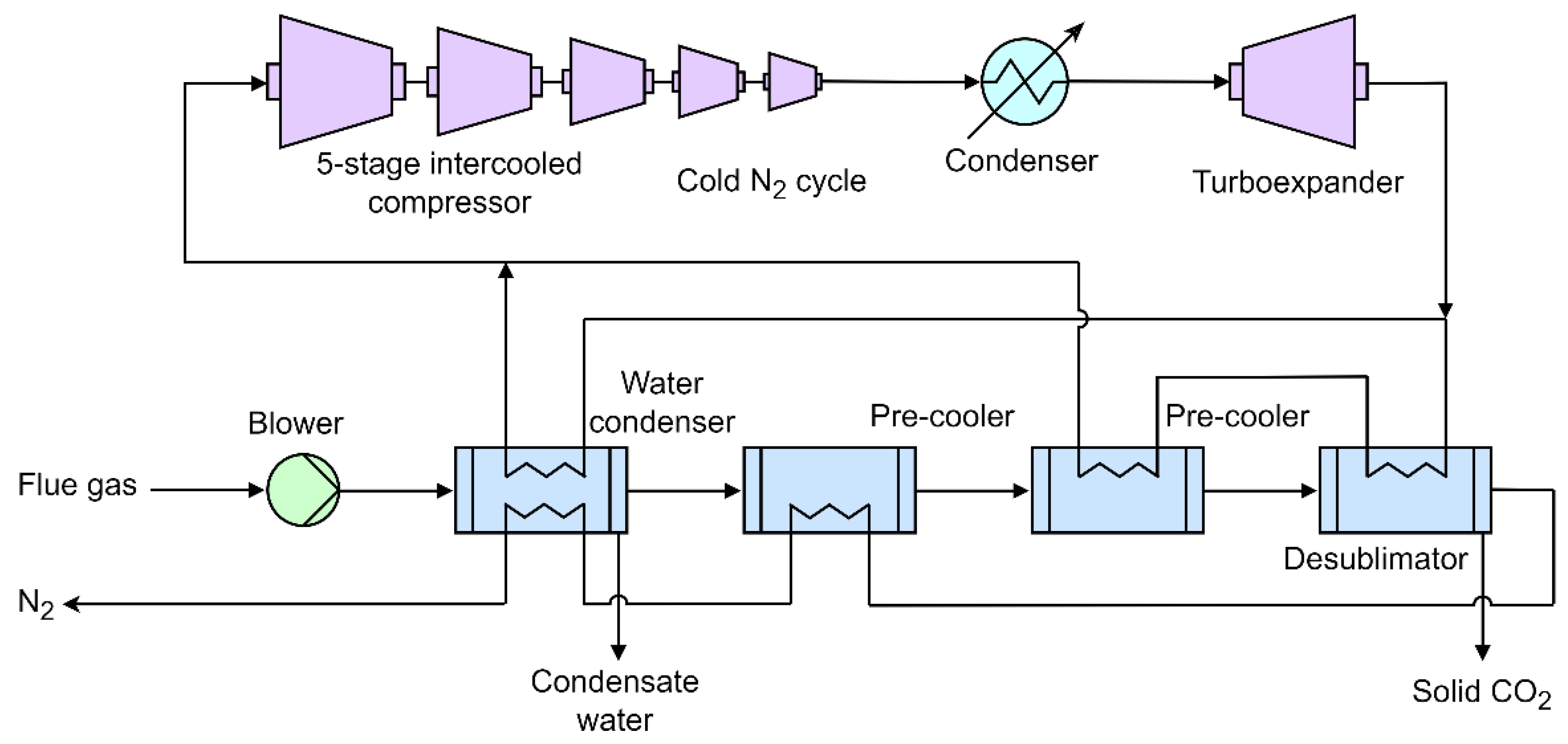
| Reference | Main content and findings |
|---|---|
| Asgarian et al. [32] | They reviewed thermodynamic framework, general models and process simulator works for calculating equipment for cryogenic process and apparatus. They also included heat exchanger modelling, particle velocity model for heat transfer from or to droplets, plug flow reactor modelling, and Aspen Plus simulations for modelling the LNG storage. |
| De Guido et al. [35], Pellegrini et al. [38] |
They implemented SRK and PR EoS to calculate solid CO2 solubilities and proposed a mathematical algorithm developed for the calculation of Solid Vapor Equilibrium stages and compared their results to Aspen RGibbs reactor. |
| Yu et al. [46] | Numerical analysis of a 1-dimensional desublimating heat exchanger. They calculated the rate of desublimation and thickness of solid formation on the walls as a function of time and location. Both the inert gas (in the gaseous mixture with CO2) and the cryogenic liquid are nitrogen. They analysed the effect of fluid mass flow rates and temperatures; they neglected the thermal resistance of the solid CO2 layer and pressure drops. |
| Berger et al. [47] | They proposed a conceptual framework to address the work of separation through cryogenic desublimation; they defined the methodologies for energy balances and energy penalties calculation and proposed the comparison to the minimum work of separation. |
| Cann [48] | The frost front velocity experiments in a fixed packed bed allowed the design of a moving packed bed (setting the bed flowrate to match the frost front velocity) to prevent the excessive accumulation of CO2 frost. He reported heat transfer coefficients, pressure drops and other fundamental correlations to describe experimental data of desublimation in a moving bed. |
| James [49] | He proposed model predicted the behaviour of a falling sphere heat exchanger in a desublimating columns for CO2 capture. Desublimation and condensation of molecules in flue gas streams occurring in a countercurrent falling sphere heat exchanger has been modelled and partially validated with experiments. The model is interesting for spray-chambers but is limited by the fact that the majority of the properties used to calculate heat transfer are at film temperature. |
| Sun et al. [50], Wu et al. [51], Wu and Webb [52] |
Frost formation and frost release on surfaces, frost growth and densification, frost release: modelling experimental results. |
| Lei et al. [53] | CO2 desublimation on a cooled cylinder surface by means of lattice Boltzmann model with 2D simulations, various behaviours in response to different operation conditions. |
| Cryogenic process | Advantages | Challenges |
|---|---|---|
| Dynamic packed bed |
|
|
| External cooling loop |
|
|
| Stirling cooler |
|
|
| AnSU |
|
|
| NLCCT |
|
|
| Cryogenic process | Feed CO2 concentration (mol%) | Cold energy source | CO2 recovery (%) |
Minimum specific energy consumption (MJe kgCO2–1) | Type of study | Reference |
|---|---|---|---|---|---|---|
| Dynamic packed bed | 10 | LNG | 99 | 3.60 | Experimental & Modelling | Tuinier et al. [56] |
| External cooling loop | 16 | Multiple refrigerants |
90 | 0.74 | Experimental & Modelling | Jensen et al. [30] |
| Stirling cooler | 13 | Stirling cooler | 95 | 0.55 | Experimental & Modelling | Song et al. [71] |
| AnSU | 12 | LNG | 90 | 1.18 | Experimental | Pan et al. [54] |
| NLCCT | 6.7 | Cold N2 gas | 99 | 0.63 | Modelling | De et al. [80] |
Disclaimer/Publisher’s Note: The statements, opinions and data contained in all publications are solely those of the individual author(s) and contributor(s) and not of MDPI and/or the editor(s). MDPI and/or the editor(s) disclaim responsibility for any injury to people or property resulting from any ideas, methods, instructions or products referred to in the content. |
© 2024 by the authors. Licensee MDPI, Basel, Switzerland. This article is an open access article distributed under the terms and conditions of the Creative Commons Attribution (CC BY) license (http://creativecommons.org/licenses/by/4.0/).


