Preprint
Article

Cross Sections for Electron Stripping, Electron Capture, and System Breakdown of C5+ and Li2+ Ions with Atomic Hydrogen

Altmetrics

Downloads

95

Views

30

Comments

0

A peer-reviewed article of this preprint also exists.

This version is not peer-reviewed

Submitted:

07 May 2024

Posted:

08 May 2024

You are already at the latest version

Alerts
Abstract
For many disciplines of science, all conceivable collisional cross sections and reactions must be precisely known. Although the recent decades were a trial of large-scale research to give these data, many essential atomic and molecular cross section data still missing, and the reliability of the existing cross sections has to be validated. In this paper, we present electron stripping, electron capture, and system breakdown cross sections in carbon (C5+) ions and lithium (Li2+) ions collisions with atomic hydrogen based on the Monte Carlo models of classical and quasi-classical trajectories. According to our expectation, the QCTMC results show higher results in comparison to standard CTMC data, emphasizing the role of Heisenberg correction constraint, especially in the low energy regime. On the Other hand, at high energy, the Heisenberg correction term has less influence as a projectile momentum increase. We present the total cross sections of electron stripping, electron capture, and system breakdown in C5+ ions and Li2+ ions collisions with atomic hydrogen in the impact energy range from 10 keV to 160 keV, which is of interest in astrophysical plasmas, atmospheric sciences, plasma laboratories, and fusion research.
Keywords: 
Subject: Physical Sciences  -   Atomic and Molecular Physics

1. Introduction

The divertor is the major part in a tokamak for plasma-surface interactions (PSI), since it is designed to manage particle and energy exhaust from the core plasma as well as impurity screening [1,2]. Divertor plasma-facing components (PFCs) are installed to provide adequate in-vessel structural protection, sufficient heat exhaust capabilities, and compatibility with plasma purity criteria [1,3]. Controlling heat flow and material erosion at divertor target plates is a critical challenge in the design and operation of next-generation high-power steady-state fusion reactors. Emission spectroscopy at the plasma edge, particularly in the limiter and divertor regions, has provided evidence for the presence of molecules and neutral atoms such as hydrogen atoms [4]. Ion recombination generates hydrogen atoms on the fusion reactor's wall and other plasma-facing components (PFCs), which can then be re-emitted into the plasma. In addition to hydrogen atoms, contaminants such as carbon, lithium, and oxygen have been found at the plasma edge region. Carbon ions and lithium ions, for example, originated primarily in the limiter and divertor, where carbon composites are utilized in the first wall tiles [5] and lithium ions are employed as a potential solution to minimize heat flow to the divertor chamber. In this paper, we focus on the atomic cross sections of collisions between neutral hydrogen atoms with carbon (C5+) ions and lithium (Li2+) ions in the limiter and divertor regions. These cross sections are of main importance to determining the reactor wall material and for modeling plasma diagnostic tools such as beam emission spectroscopy devices (BES) [6,7,8,9]. This work is created toward developing theoretical computation frameworks that can give the total cross section for different inelastic processes accurately. In this paper, we study the total cross sections of the electron stripping, the electron capture, and the system breakdown in a collision between carbon (C5+) ions and lithium (Li2+) ions with ground state hydrogen atoms, as described below (see Equations (1)–(4)).
A x + + H A x + 1 + H + e A     ( E l e c t r o n   s t r i p p i n g   p r o c e s s )
A x + + H A x + 1 + H   ( E l e c t r o n   c a p t u r e   o f   t h e   t a r g e t )
A x + + H A ( x + ) 1 + H +   ( E l e c t r o n   c a p t u r e   o f   t h e   p r o j e c t i l e )
A x + + H A x + 1 + H + + e A + e H     ( S y s t e m   b r e a k d o w n )
In the 1960s, the classical trajectory Monte Carlo calculations of cross section (CTMC) was developed [10]. This method of calculation has proven its effectiveness with high accuracy, especially in the medium energy region [7,8,9,10,11,12,13], where it is deemed non-perturbative method and has the benefit of being able to compute more than one interaction channel at the same time [7,8,9,10,11,12,13]. In order to increase the validity of this method to cover a wider range of energy regimes, it was necessary to develop the calculation method by adding some quantum constraints, which played an important role in improving the accuracy of classical calculations in the low energy regime [5,9,14,15]. These constraints impose on the energy of the system for a more stable atomic structure via applying a Kirschbaum and Wilets method [16,17], resulting in a quasiclassical trajectory Monte Carlo model (QCTMC). In this paper, we present the total cross sections of electron stripping, electron capture, and system breakdown in the collision of carbon (C5+) ions and lithium (Li2+) ions with atomic hydrogen in the range of energy from 10 keV to 160 keV, which is of interest in the field of fusion, astrophysical plasmas [18], and environmental sciences. The atomic unit is used throughout unless otherwise specified.

2. Theory

2.1. The CTMC Models

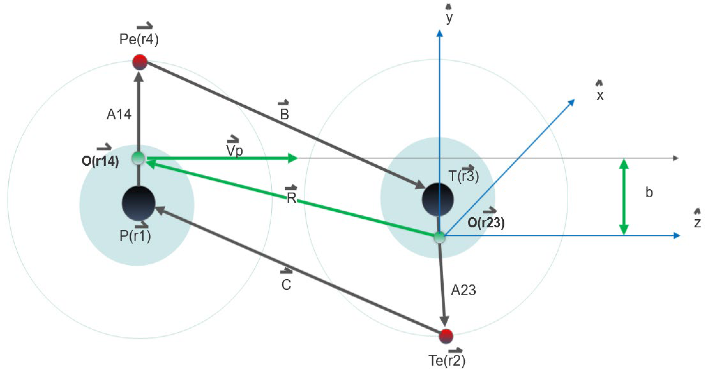
As is well-known, classical descriptions of collision processes work extremely well [5,7,19,20]. In this model, the H atom is represented by two particles representing its ionic core of H as well as one active electron; all particles can be described by their masses and charges [15,17]. Let P stands for the ionic core of the projectile, Pe stands for the electron of the projectile, T stands for the ionic core of the target, and Te stands for the electron of the target [15]. Interactions between electrons are explicitly taken into account in our four-body calculations. At the time (t = -∞), assume the four-body collision system is made up of two isolated atoms, a projectile atom (P, Pe) marked as particles (1, 4) and a target atom (T, Te) marked as particles (2, 3), see Figure 1 [14,15]. At the beginning, both particles are in the ground state (nl=1, 0) [14,15]. We used the Coulomb potential to describe all interactions [14,15]. Figure 1 depicts relative position vectors for four-body collision systems.
The initial electronic states can be determined by means of a microcanonical distribution. A microcanonical set represents the initial state of the target and projectile compelled by their binding energy in any given shell and can be described as follows:
ρ E 0 ( A , A ˙ ) = K 1 δ ( E 0 E ) = δ E 0 1 2 μ T , T e , P , P e A ˙ 2 V ( A ) .
Where K1 serves as a normalization constant, while E0 denotes the ionization energy [5,7,8,9,14,15]. According to the Equation (5), the electronic coordinates are restricted within intervals where Equation (6) holds true:
1 2 μ T e A ˙ = E 0 V ( A ) > 0 .
The Hamilton equation is given by:
H 0 = T + V c o u l ,
where
T = P p 2 2 m p + P p e 2 2 m p e + P T 2 2 m T + P T e 2 2 m T e ,
and
V c o u l = Z p Z P e r p r P e + Z P Z T r P r T + Z p Z T e r p r T e + Z p e Z T r p e r T + Z P e Z T e r p e r T e + Z T Z T e r T r T e .
Where T and Vcoul, respectively, stand for total kinetic energy and Coulomb potential term [5,7,8,9,14,15]. P , Z, r , and m stand for momentum vector, charge, position vector, and mass of each particle [5,7,8,9,14,15]. Here are the equations of motion according to Hamiltonian mechanics:
P ˙ p = δ H 0 δ r P = Z P Z P e r p r P e 3 r P r P e + Z P Z T r P r T 3 r P r T + Z P Z T e r P r T e 3 r P r T e ,
P ˙ P e = δ H 0 δ r P e = Z P Z P e r P r P e 3 r P r P e Z T Z P e r T r P e 3 r T r P e Z T e Z P e r T e r P e 3 r T e r P e ,
P ˙ T = δ H H 0 δ r T = Z P Z T r P r T 3 r P r T Z T e Z T T e r T 3 r T e r T + Z T Z P e r T r P e 3 r T r P e ,
P ˙ T e = δ H H 0 δ r T e = Z P Z T e r P r T e 3 r P r T e Z T e Z T T e r T 3 r T e r T Z T e Z P e r T e r P e 3 r T e r P e .
The Runge-Kutta method is typically utilized to numerically integrate equations of motion using an ensemble of approximately 5x10⁶ primary trajectories per energy [5,7,8,9,14,15]. Such an ensemble typically is required in order to ensure statistical uncertainties of less than 5% [5,7,8,9,14,15]. The total cross section is given by:
σ = 2 π b m a x N j b j ,
Where b j is the impact parameter corresponding to the trajectory associated with a specific process such as electron stripping, electron capture, or system breakdown. N is the total number of calculated trajectories. bmax is the maximum value for the impact parameter where the processes described can take place. The statistical uncertainty of the total cross section can be calculated by:
σ = σ N N P N N P 1 / 2 .
Where, N P , is the number of trajectories that meet the requirements for a particular process.

2.2. The QCTMC Model

The QCTMC model was first introduced by Kirschbaum and Wilets [16,17] as an enhanced rendition of the conventional CTMC model, incorporating a quantum correction term that accounts for the Heisenberg uncertainty and Pauli principle [5,7,8,9,14,15]. In order to simulate the Heisenberg uncertainty and Pauli principle, a modified Hamiltonian effective potential (VH for Heisenberg and VP for Pauli) is added to the pure Coulomb inter-particle potentials to represent a non-classical effect [16,17]. As a result, inter-particle interactions are enhanced. Thus:
H Q C T M C = H 0 + V H + V P .
Where H0 is the standard Hamiltonian (see Equation (7)); and correction terms for H0 include:
V H = i = 1 N 1 m r i 2 f r i , p i ; ξ H ; α H ,
and
V p = i = 1 N j = i + 1 N 2 m r i j 2 f r i j , p i j ; ξ p ; α p δ s i , s j .
Where the i, j are the electron’s index. Additionally, r i j = r j r i and relative momentum determined as follows:
P i j = m i p j m j p i m i + m j
If the spin of the ith and jth electrons is the same,   δ s i , s j = 1 , otherwise, if they have different spins,   δ s i , s j = 0 . Finally, the selected constraining potential is:
f r λ ν , p λ ν ; ξ , α = ξ 2 4 α r λ ν 2 μ λ ν e x p α 1 r λ ν p λ ν ξ 4
Due to the fact that a hydrogen atom is composed of a single electron and a single proton, the Heisenberg constraints are applied with a distinct scale parameter, a hardness parameter ( α H = 3.0), and a dimensionless constant ( ξ H = 0.9258) were applied to the four-body QCTMC model. As illustrated in a given formula 21:
f r T , T e , P T , T e ; ε H , α H = ξ H 2 4 α H r T , T e 2 μ T , T e e x p α H 1 r T , T e P T , T e ξ H 4 .
Similar to the target atom, the correction term should be also added to the projectile atom as follows:
f r P , P e , P P , P e ; ε H , α H = ξ H 2 4 α H r P , P e 2 μ P , P e e x p α H 1 r P , P e P P , P e ξ H 4 .
As shown in Figure 1, equations of motion which incorporate Hamiltonian mechanics as well as correction terms for cross section calculations can be expressed as:
P ˙ p = δ H Q C T M C δ r P = Z P Z P e r p r P e 3 r P r P e ξ H 2 2 α H r P , P e 4 μ P , P e P P , P e 4 μ P , P e ξ H 2 e x p α H 1 r P , P e P P , P e ξ H 4 + Z P Z T r P r T 3 r P r T + Z P Z T e r P r T e 3 r P r T e ,
P ˙ P e = δ H Q C T M C δ r P e = Z P Z P e r P r P e 3 r P r P e + ξ H 2 2 α H r P , P e 4 μ P , P e P P , P e 4 μ P , P e ξ H 2 e x p α H 1 r P , P e P P , P e ξ H 4 Z T Z P e r T r P e 3 r T r P e Z T e Z P e r T e r P e 3 r T e r P e ξ P 2 2 α P r T e , P e 4 μ T e , P e P T e , P e 4 μ T e , P e ξ H 2 e x p α p 1 r T e , P e P T e , P e ξ P 4 ,
P ˙ T = δ H Q C T M C δ r T = Z P Z T r P r T 3 r P r T Z T e Z T T e r T 3 r T e r T + ξ H 2 2 α H r T , T e 4 μ T , T e P T , T e 4 μ T , T e ξ H 2 e x p α H 1 r T , T e P T , T e ξ H 4 + Z T Z P e r T r P e 3 r T r P e ,
P ˙ T e = δ H Q C T M C δ r T e = Z P Z T e r P r T e 3 r P r T e Z T e Z T T e r T 3 r T e r T + ξ H 2 2 α H r T , T e 4 μ T , T e P T , T e 4 μ T , T e ξ H 2 e x p α H 1 r T , T e P T , T e ξ H 4 Z T e Z P e r T e r P e 3 r T e r P e ξ P 2 2 α P r T e , P e 4 μ T e , P e P T e , P e 4 μ T e , P e ξ H 2 e x p α p 1 r T e , P e P T e , P e ξ P 4 .

3. Result and Discussion

2.1. Carbon (C5+) - Hydrogen (H) Collision Cross Sections

Most current fusion reactors employ carbon (C) and tungsten (W) as the primary PFCs. C-PFCs are primarily selected for their exceptional ability to withstand thermal shock and endure out-of-the-ordinary events without melting [1,2,21]. C-PFCs, on the contrary, experience significant erosion due to both physical sputtering and chemical erosion, even at low plasma edge temperatures. The presence of a small amount of carbon in the reactor area, such as a limiter and divertor, due to physical sputtering and chemical erosion, may enhance a variety of inelastic interactions with hydrogen atoms and other impurities, which may affect reactor operation efficiency [5]. In the previous paper [5], the ionization and the electron capture cross sections of hydrogen target by C5+ impact have been discussed using both CTMC and QCTMC models. At low energies, the hydrogen target's total ionization cross section by C5+ impact was observed to be elevated. Which can be attributed to the prevalence of electron-electron interactions in the low energy region. This claim was confirmed by a reduced version of the Monte Carlo code. Alongside, in this section, we present the electron stripping and the system breakdown cross sections in a C 5 + + H collision, see Equations (27) and (28).
At first, let’s start with electron stripping channel when the projectile increased by one and hydrogen atom remains unchanged after collision, see Equation (27):
C 5 + + H C 6 + + H + e C
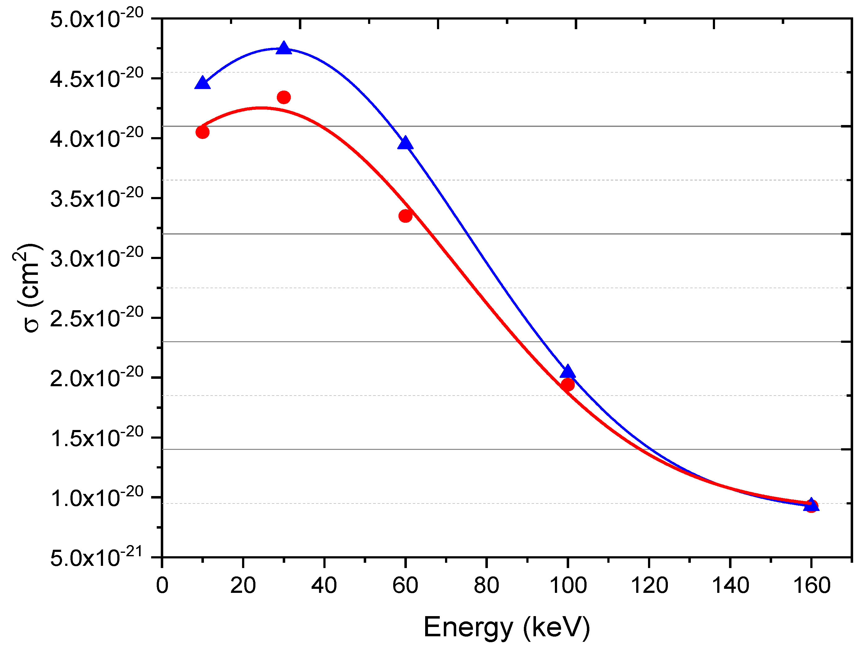
Figure 2 illustrates the projectile's total electrons stripping cross section as a function of impact energy within the energy range of 10 keV to 160 keV. This data is crucial for fusion research and has been calculated using both the CTMC and QCTMC models. The probability peak at 55 keV is also seen in Figure 2. The QCTMC findings show a slight elevation compared to the standard CTMC calculations in the low-energy regions below 100 keV, thereby affirming the significance of the Heisenberg correction term. On the other hand, in the high energy range above 100 keV, when the projectile's energy (velocity) is greater than that of an orbital electron ( v p v e ), the Heisenberg correction component is minimal (see Figure 2), which means that the CTMC and QCTMC calculations have roughly similar results, and this can be explained by two factors 1) The Heisenberg potential has less influence as projectile momentum increases, and 2) The Heisenberg potential is inversely proportional to the square of the relative distance between colliders   ( V H   α   1 r i j 2 ) , see Equation (20). As a result, the V H ( r , p , α ) potential contributes in the low-to-medium energy region and is negligible in the high-energy region. However, there were no previous theoretical or experimental data to compare.
Simultaneously, the breakdown channel of the C 5 + + H collision system was defined as:
C 5 + + H C 6 + + H + + e C + e H    
Figure 3 displays the ionization cross sections of both the target and the projectile using the CTMC and the QCTMC methods, yielding the final state of the four free particles as a function of projectile impact. The peak maxima of the cross section is about 30 keV, indicating that the system breakdown cross sections have a high probability at low energy. Furthermore, in comparison to inelastic processes such as electron stripping, excitation, and electron capture, the C 5 + + H collision system has the lowest probability of system breakdown over a wide energy scale. Similarly, as noticed above, CTMC and QCTMC calculations produce the same results in the high energy region above 100 keV, emphasizing the Heisenberg constraints can be negligible at high energy regime.

2.2. Lithium (Li2+) - Hydrogen (H) Collision Cross Sections

The incredible effects of lithium on a fusion reactor's plasma boundary were initially observed in a tokamak operating in limiter mode without a divertor [22]. It has been found that the energy confinement duration of the discharge in [22,23] a keV temperature plasma edge was significantly enhanced by the pulses that were preceded by lithium pellet injections [22,24]. In addition, lithium has become increasingly recognized as a potential solution to combating divertor heat flux issues within fusion reactors, as ionized lithium atoms form highly radiative plasma layers which could significantly decrease heat flow into divertors surfaces [25,26,27,28,29,30]. As it happens, evaporated lithium in its ionic form (partially stripped ions) combined with hydrogen, carbon, and oxygen atoms increased the possibility for inelastic collisions between multiply charged ions and neutral atoms - stimulating inelastic collision research not only out of general scientific curiosity but also as essential tools in fusion-related research [5]. The interaction between ions and H-target, for instance, have a vital role in determining radiation losses, beam penetration efficiency (ionization rate), and reducing the heat flux to the divertor surfaces [29] in tokamak plasmas. In this section, we present the total cross sections of the electron stripping, the electron captures of the target, the electron captures of the projectile, and the system breakdown in a L i 2 + + H collision system, see Equations (29)–(32).
At first, let us commence by discussing the electron stripping channel, wherein the projectile charge is incremented by one while the hydrogen target remains unchanged after the collision, see Equation (29):
L i 2 + + H L i 3 + + H + e L i
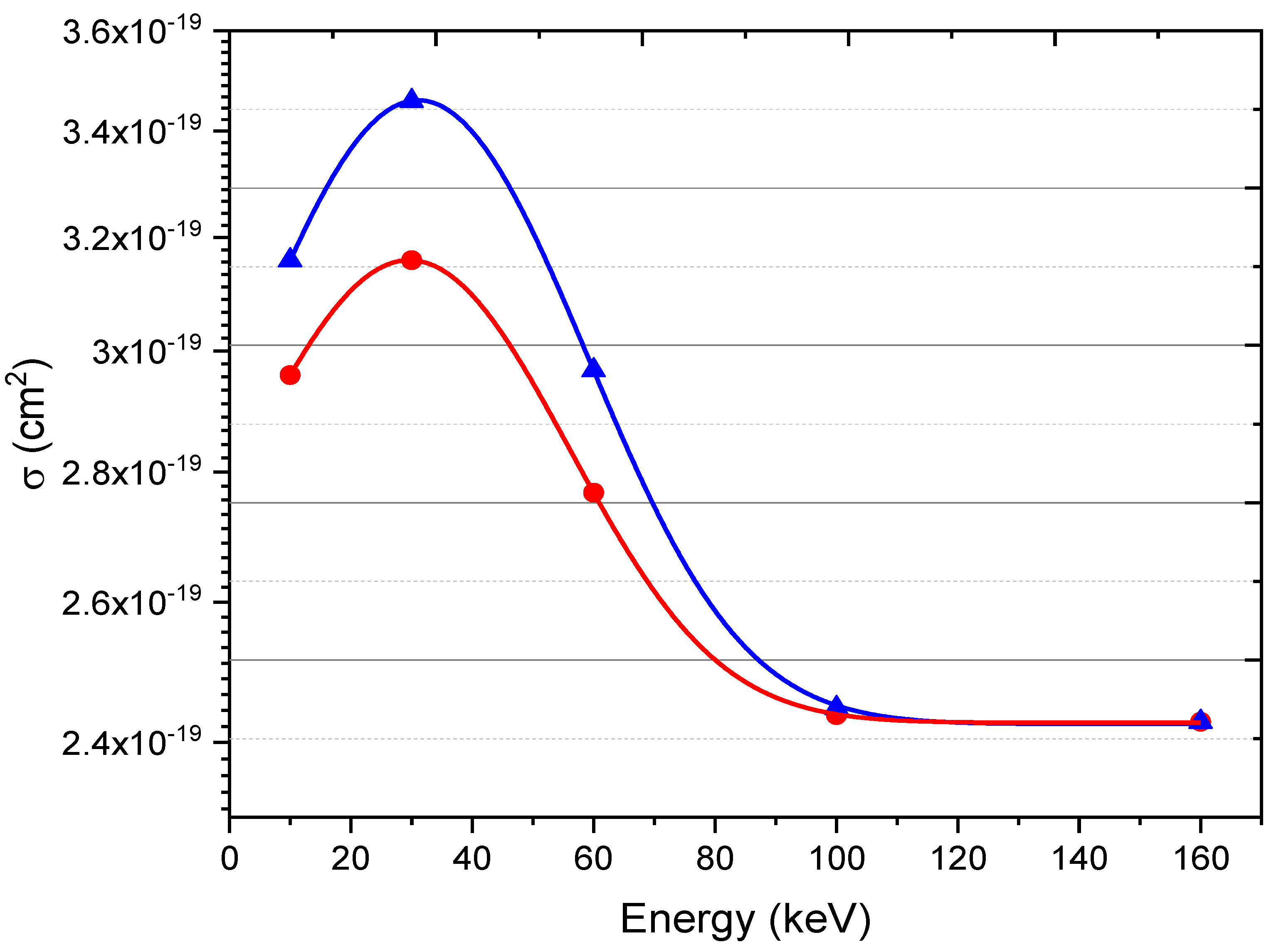
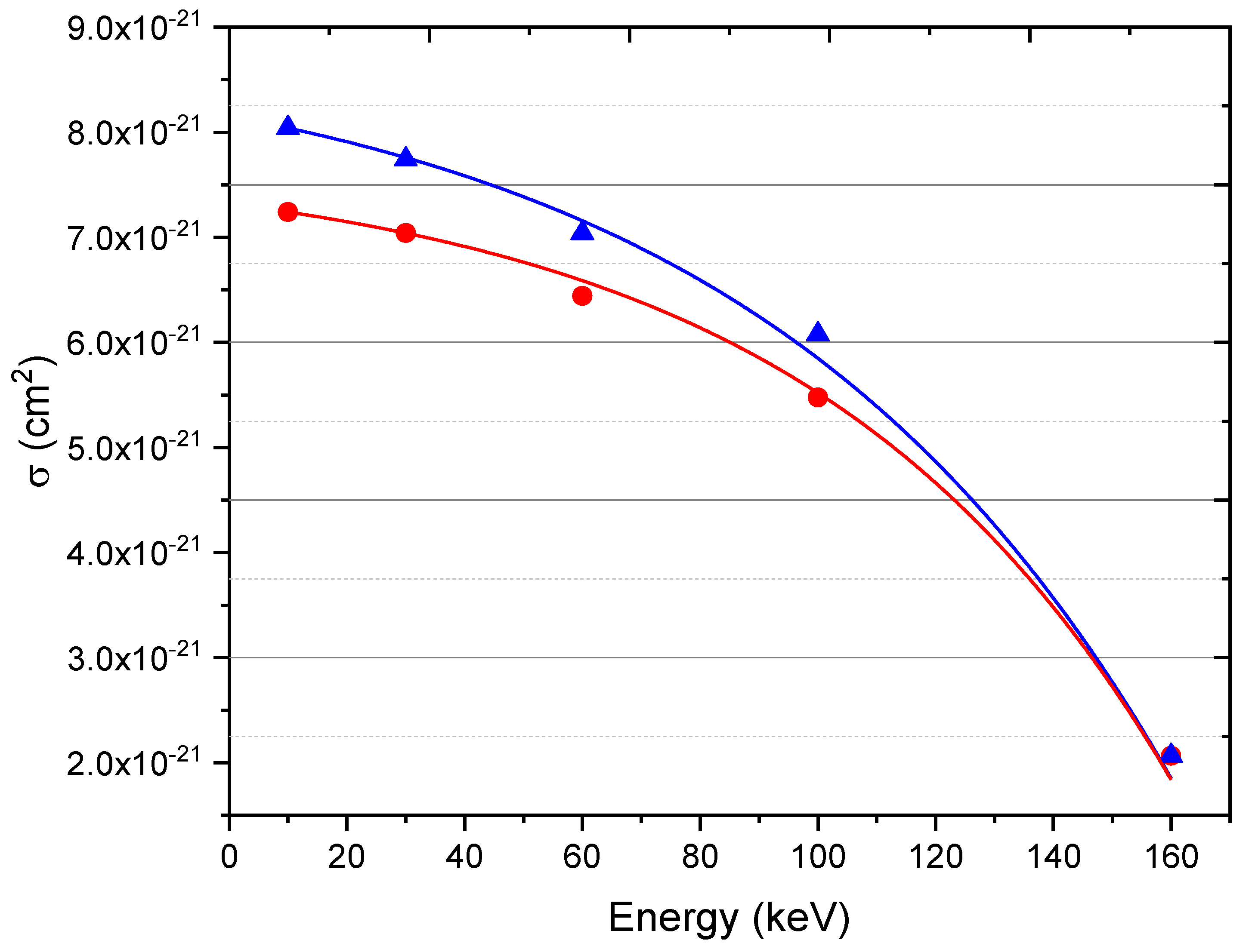
Figure 4 illustrates the electron stripping cross section in a L i 2 + + H collision as a function of impact energy using CTMC and QCTMC calculation methods. The electron stripping cross sections were fitted by Gaussian curves. The peak maxima appear at 30 keV and this can be explained by using basic kinematic picture. During the collision, at low impact energy, the projectile overlaps with the target atom and remains close to the target for an extended period of time, increasing the possibility of electro stripping process owing to the increased probability of interaction among ionic cores, electrons, and ionic cores-electrons (slow-collision). Furthermore, the QCTMC results, as expected, are greater than the regular CTMC results, this observation clearly illustrates the impact of the quantum correction term in the low energy regime. For high-energy regime, above 100 keV, both the CTMC and QCTMC models provide identical results due to the fact that the Heisenberg correction term influence decrease as the projectile momentum increases. Our model has been validated against both experimental and theoretical calculation approaches [5,9,14,15], despite the absence of any previous data for comparison with present calculation.
Simultaneously, we considered the electron capture of the target cross section, see Equation (30):
L i 2 + + H L i 3 + + H    
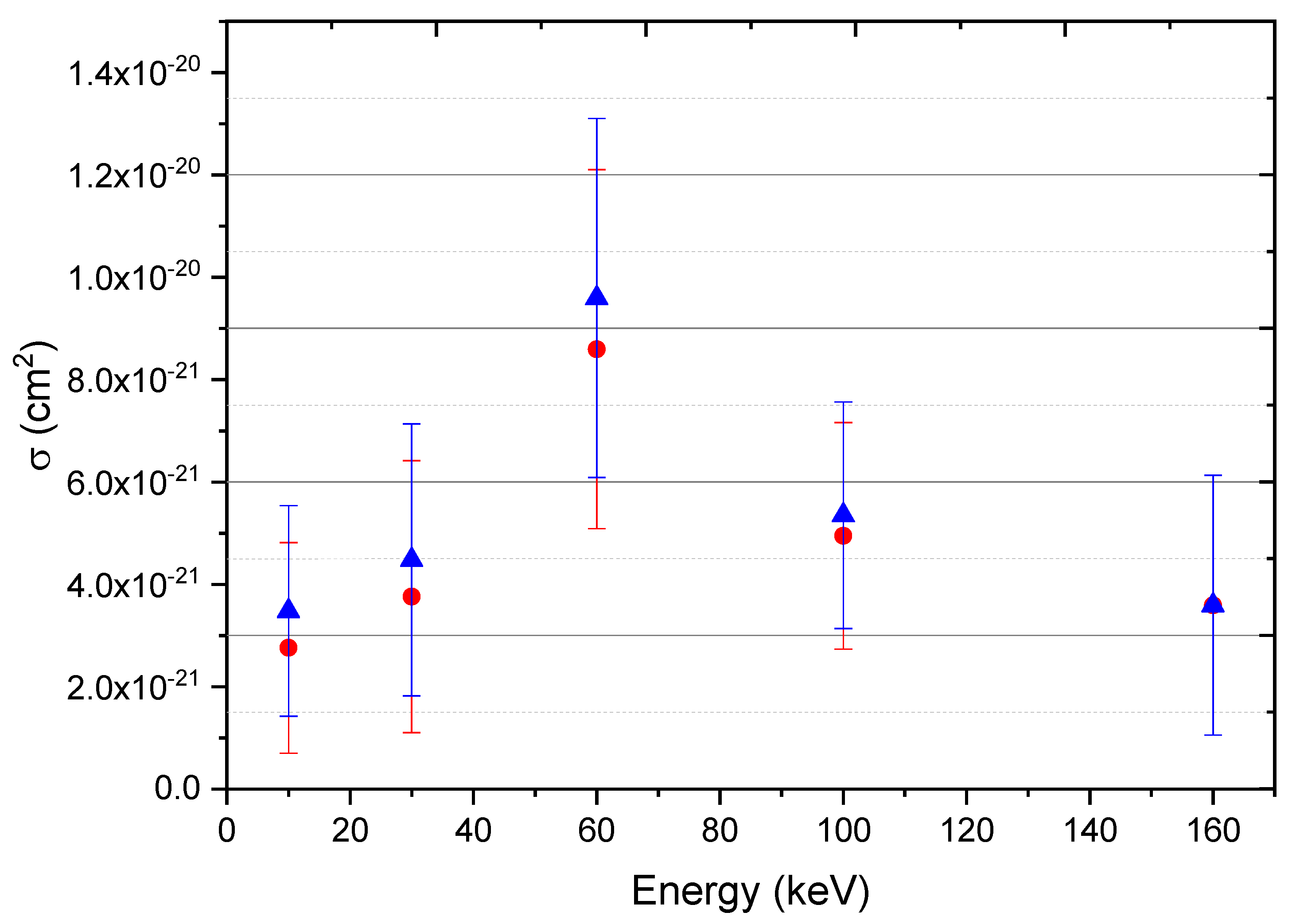
Figure 5 depicts the electron capture cross section of the target in a L i 2 + + H collision as a function of impact energy using both CTMC and QCTMC calculation methods. The probability peak at 60 keV is also seen in Figure 5. However, according to our expectation, the QCTMC results are slightly higher than typical CTMC calculations, emphasizing the role of the Heisenberg correction term at low energy regime. At high energy region, the CTMC and QCTMC results are roughly the same.
Similarly, as in the case of the electron capture of the target, we also calculated the electron capture cross section of the projectile, as described in Equation (31):
L i 2 + + H L i + + H +    
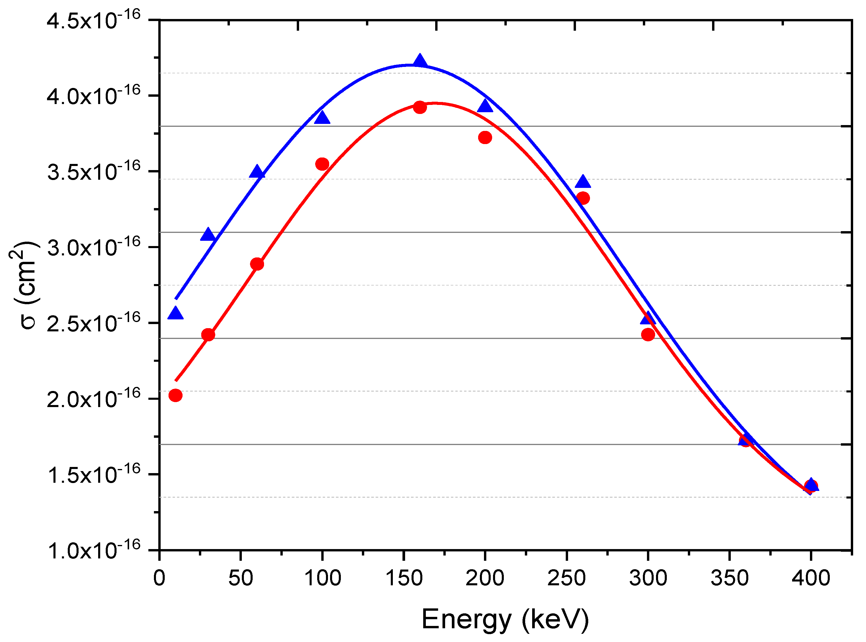
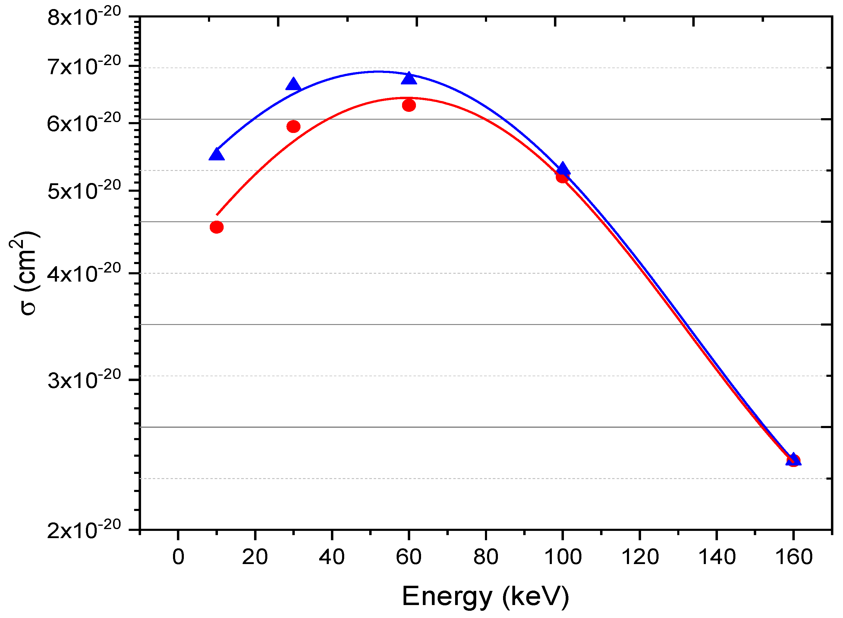
Figure 6 depicts the electron capture cross section of the projectile as a function of impact energy between 0.1 keV to 400 keV using CTMC and QCTMC methods. The probability peak appears at 160 keV. At low to intermediate energy regions, the QCTMC results are higher than the CTMC data, indicating the relevance of quantum features in enhancing cross section results, particularly at low energy regime. On the other hand, in the high energy area, both QCTMC and CTMC produce the same results, demonstrating that the Heisenberg correction term can be insignificant in this energy zone as mentioned earlier. Furthermore, as we noticed, the probability of the electron capture process for the projectile in a L i 2 + + H collision is dominant and this can be justified by considering the nuclear charge effect, when the nuclear charge increase, the capability to attract high-velocity electrons increases.
Finally, the breakdown channel of the L i 2 + + H collision system was defined as:
L i 2 + + H L i 3 + + H + + e L i + e H    
Figure 7 shows the complete break of the L i 2 + + H collision system as a function of impact energy using both QCTMC and CTMC calculation models. The peak maxima of the cross section is about 10 keV. As we expected, QCTMC improves the cross section results at low energy regime.
4. Conclusions

We presented the total cross sections in C5+ + H and Li2+ + H collisions using both four-body CTMC and four-body QCTMC calculation methods. Our calculations were performed for impact energy ranging from 10 to 160 keV, where the cross sections are predicted to be relevant to astronomical plasmas, atmospheric sciences, plasma laboratories, and fusion research interests. We found the CTMC calculations were a little bit underestimated the recent QCTMC results, demonstrated the role of quantum features on the cross section calculations in the low energy zone. Nonetheless, the CTMC results showed an identical result to the new model (QCTMC) at the energy high energy region. In conclusion, we found that the cross section results at low energy regimes were enhanced by the Heisenberg correction term, while its impact diminished with an increase in projectile momentum.

Acknowledgement

This work has no fund.

References

  1. Sang C, Rui Ding, Xavier Bonnin, Liang Wang, Dezhen Wang and EAST Team 2018 Physics of Plasmas. 7 25.
  2. Federici G, Skinner C H, Brooks J N, Coad J P, Grisolia C, Haasz A A, Hassanein A, Philipps V, Pitcher C S, Roth J, Wampler W R, and Whyte D G 1967 Nucl. Fusion 41 1967.
  3. Pitts R A, Carpentier S, Escourbiac F, Hirai T, Komarov V, Kukushkin A S, Lisgo S, Loarte A, Merola M, Mitteau R, Raffray A R, Shimada M and Stangeby P C 2011 J. Nucl. Mater. 415 S957.
  4. Iztok Čadež, Sabina Markelj, Zdravko Rupnik and Primož Pelicon 2008 J. Phys: Conf. Series 133 012029.
  5. Atawneh S J A and Tokesi K 2021 Nucl. Fusion. 62 026009>Nucl.
  6. Guszejnov D, Pokol GI, Pusztai I, Refy D, Zoletnik S, Lampert M and Nam Y U 2012 Review of Scientific Instruments. 83 113501.
  7. Atawneh S J A, Asztalos Ö, Szondy B, Pokol G I and Tőkési K 2020 Atoms. 8 31.
  8. Atawneh S J A and Tőkési K 2021 J. Phys. B: At. Mol. Opt. Phys. 54 065202.
  9. Atawneh S J A and Tőkési K 2022 Atomic Data and Nuclear Data Tables. 146 101513.
  10. Bunker D L, Nature (London) 194, 1277 (1962); Blais N C and Bunker D L, J. Chem. Phys. 3'7, 2713 (1962); Karplus M and Raff L M, ibid 41, 1267. (1964); Herschbach D R, Adv. Chem. Phys. 10, 319 (1966); for a detailed review, see Porter R N and Raff L M, in Dynamics of Molecular Collisions, edited by Miller W H (Plenum, New York, 1976), pt. B, pp. 1–52.
  11. Olson R E, Reinhold C O and Schultz D R, in High-energy ion-atom collisions, Proceedings of the 4th Workshop on High-Energy Ion-Atom Collision Processes, Debrecen, Hungary, 17-19 September 1990, edited by Berenyi D, Hock G, Lecture Notes in Physics (1991), Vol. 376, p. 69.
  12. brines R and Percival I C 1966 Proc. Phys. Soc. 88 861-872.
  13. Janev R K and McDowell M R C 1984 Phys. Lett. A. 102 405-408.
  14. Atawneh S J A. Modelling of atomic processes in fusion plasma.2022. Debrecen U, PhD dissertation. ProQuest, http://hdl.handle.net/2437/329082.
  15. Atawneh S J A and Tőkési K 2022 Phys. Chem. Chem. Phys. 24 15280-15291.
  16. Wilets L and Cohen L S 1998 Cont. Phys. 39 163-175.
  17. Kirschbaum C L and Wilets L 1980 Phys. Rev. A. 21 834-841.
  18. Suno H and Kato T 2006 Atomic Data and Nuclear Data Tables. 92(4): p. 407-455.
  19. Velayati A and Ghanbari-Adivi E 2018 Eur. Phys. J. D.
  20. Ghavaminia H and Ghanbari-Adivi E 2015 Chinese Phys. B. 24 073401.
  21. Federici G, Andrew P, Barabaschi P, Brooks J, Doerner R, Geier A, Herrmann A, Janeschitz G, Krieger K, Kukushkin A, Loarte A, Neu R, Saibene G, Shimada M, Strohmayer G, Sugihara M, and. Co-center I J W S G 2003 J. Nucl. Mater. 11 313–316.
  22. de Castro A, Moynihan C, Stemmley S, Szott M and Ruzic D N 2021 Physics of Plasmas. 5 28.
  23. Strachan J D 1994 Nucl. Fusion. 34 1017.
  24. Majeski R 2010 AIP Conf. Proc. 122 1237.
  25. Ono M, Lithium As Plasma Facing Component for Magnetic Fusion Research. 2012, Nova Scientific Publications (August 2012); Princeton Plasma Physics Lab. (PPPL), Princeton, NJ (United States). p. Medium: ED.
  26. Skokov V G, Sergeev V Y, Anufriev E A and Kuteev B V 2021 Tech. Phys. 66 664–674.
  27. Goldston R J, Myers R and Schwartz 2016 J. Phys. Scr. T167 014017.
  28. Kaita R 2019 Plasma Phys. Control. Fusion. 61 113001.
  29. Rognlien T D and Rensink M E 2002 Phys. Plasmas. 9 2120-2126.
  30. Mirnov S V, Azizov E A, Evtikhin V A, Lazarev V B, Lyublinski I E, Vertkov A V and Yu Prokhorov D 2006 Plasma Phys. Control. Fusion. 48 821-837.
Figure 1. The schematic diagram represents the relative position vectors for particles involved in our 4-body collision systems. A 14 = r 4 r 1 ,   B = r 4 r 3 , A 23 =   r 3 r 2 , and C = r 2 r 1 , in such way that A 14 + A 23 + B + C = 0 . Where O ( r 14 ) and O ( r 23 ) represent centre-of-mass vectors for target and projectile systems respectively, with b as their impact parameter.
Preprints 105900 g001
Figure 2. Electron stripping cross sections in a C5+ + H collisions as a function of impact energy. Red circles: the CTMC results. Blue triangles: The QCTMC results. The plotted line represents the outcome of the best fitting 'Gaussian curve' to the calculated data in order to provide a visual guide.
Preprints 105900 g002
Figure 3. System breakdown cross sections in a C5+ + H collisions as a function of impact energy. Red circles: the CTMC results. Blue triangles: The QCTMC results. The plotted line represents the outcome of the best fitting 'Gaussian curve' to the calculated data in order to provide a visual guide.
Preprints 105900 g003
Figure 4. Electron stripping cross sections in a Li2+ + H collisions as a function of impact energy. Red circles: the CTMC results. Blue triangles: The QCTMC results. The plotted line represents the outcome of the best fitting ‘Gaussian curve’ to the calculated data in order to provide a visual guide.
Preprints 105900 g004
Figure 5. The electron captures cross sections of the hydrogen target in a Li2+ + H collisions as a function of impact energy. Red circles: the CTMC results. Blue triangles: The QCTMC results.
Preprints 105900 g005
Figure 6. The electron captures cross sections of the projectile in a Li2+ + H collisions as a function of impact energy. Red circles: the CTMC results. Blue triangles: The QCTMC results. The plotted line represents the outcome of the best fitting 'Gaussian curve' to the calculated data in order to provide a visual guide.
Preprints 105900 g006
Figure 7. System breakdown in a Li2+ + H collisions as a function of impact energy. Red circles: the CTMC results. Blue triangles: The QCTMC results. The plotted line represents the outcome of the best fitting ‘Exponential curve’ to the calculated data in order to provide a visual guide.
Preprints 105900 g007
Disclaimer/Publisher’s Note: The statements, opinions and data contained in all publications are solely those of the individual author(s) and contributor(s) and not of MDPI and/or the editor(s). MDPI and/or the editor(s) disclaim responsibility for any injury to people or property resulting from any ideas, methods, instructions or products referred to in the content.
Copyright: This open access article is published under a Creative Commons CC BY 4.0 license, which permit the free download, distribution, and reuse, provided that the author and preprint are cited in any reuse.
Prerpints.org logo

Preprints.org is a free preprint server supported by MDPI in Basel, Switzerland.

Subscribe

© 2024 MDPI (Basel, Switzerland) unless otherwise stated