Graphical Abstract:
1. Introduction
Microfiltration membranes have been extensively employed in water purification systems, where their widespread usage surpasses traditional thermal-based separation methods [
1,
2]. Distinguished by fine pore sizes ranging from 0.1 to 10 µm, these membranes effectively eliminate suspended particles and impurities from water through compact design and low energy expenditure, employing the physical size exclusion principle [
3]. This distinct approach not only facilitates efficient separation but also eliminates the need for high temperatures, rendering microfiltration a cost-effective solution for water treatment [
3,
4,
5].
Electrospinning is a widely recognized process for the continuous production of fibrous filtration membranes, with fibers ranging from sub-micron to nano-size [
3]. However, this technique is limited to the polymers that are soluble at room temperature, and cannot be used for semi-crystalline polymers such as polyolefins, that include polypropylene (PP) and high density polyethylene (HDPE) [
3,
6]. Besides, polyolefins are the major component of total plastic waste due to their extensive usage as commodity plastics [
7,
8]. Hence, there should be a technique that caters semi-crystalline polymers and their recycled plastic form.
An alternative method for synthesizing microfiltration membranes utilizing semi-crystalline polymers involves extrusion–hot-pressing technique. In this process, a polymer is extruded alongside particulate matter or filler [
9]. The resulting extruded gel undergoes subsequent hot-pressing or extrusion casting to shape a thin sheet. This sheet is then subjected to hot-drawing, either uniaxially or biaxially, creating pores at the interface between the polymer and filler [
9,
10,
11,
12,
13,
14]. Widely adopted in commercial applications, this extrusion–stretching route has proven to be efficient and scalable [
9,
15,
16]. Notably, polyethylene (PE) is among the most preferred polymers due to its favorable attributes, which include low cost, processability, scalability, and versatility [
17,
18,
19,
20,
21,
22].
Despite its notable advantages, the extrusion-stretching route comes with inherent challenges. This method demands a substantial quantity of polymer, leading to prolonged casting times due to the involvement of multiple steps. Additionally, it imposes high energy requirements and generates a considerable amount of waste. In contrast, spin-casting emerges as a favorable technique for low-scale and laboratory setups, offering advantages such as reduced polymer requirements, shorter casting times, and minimized wastage.
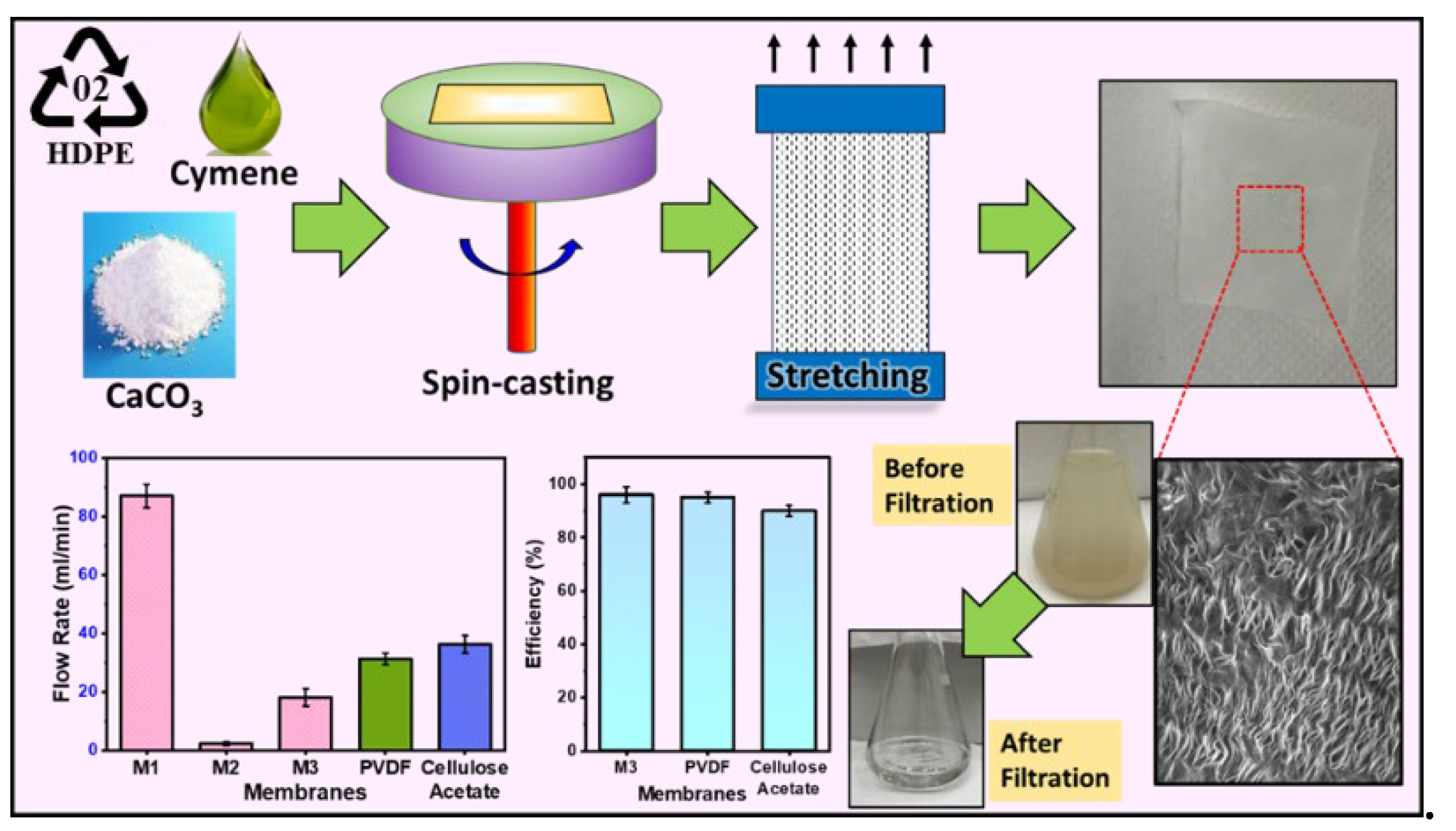
In this study, our objective is to synthesize a microfiltration membrane based on semi-crystalline polymers or plastics, employing a unique combination of spin-casting, annealing, and stretch-induced pore formation. We present a microfiltration membrane synthesized from a blend, combining recycled HDPE and virgin polyethylene powder in a ratio of 30:70 wt. %, along with the inclusion of calcium carbonate (CaCO3) as a filler. The membrane is specifically designed to efficiently remove suspended particles from water. Various combinations of polymer and inorganic filler were examined, with and without stretching, and the optimum conditions were achieved based on uniformity of pores and the overall strength of the membrane. The flow rate and mechanical strength of as-prepared membranes were compared with the commercial microfiltration membranes. The integration of stretch-induced thin film membranes for semi-crystalline polymers using spin-casting provides an alternate in the realm of microfiltration technology.
2. Experimental Section
2.1. Materials and Methods
p-cymene was used as a solvent and purchased from Njnq Bio-tech Ltd. Waste HDPE bottles were collected locally. Ultrahigh molecular weight polyethylene (UHMWPE) with a molecular weight of 3-6 million from Sigma was used as received. CaCO3 was procured from Sigma and used as a filler without further purification. A customized glass plate with an area of 25 cm2 served as the solid substrate for membrane fabrication. These plates were specifically tailored to fit onto the chuck of the coater. The annealing of the thin membrane films was conducted on a Heidolph hot plate.
2.2. Formulation and preparation of polyethylene and filler composite membranes
Preparation of M1 membrane: A total of 700 mg of UHMWPE and 300 mg of HDPE were weighed and placed in a round-bottomed flask. Subsequently, 100 ml of p-cymene was added to the flask and heated to 130-135 °C. The solution was stirred for 15-20 min or until complete dissolution of the polymers occurred. This resulting solution was termed as M1 solution and was then poured onto the glass substrate and allowed to spin. The spin coating process involved four steps: 300 rpm for 10 sec (step one), 700 rpm for 30 sec (step two), 1000 rpm for 60 sec (step three), and 3000 rpm for 120 sec (step four). Subsequently, the glass substrate with the polymer was detached from the chuck and placed on a hot plate at 130 °C for 2-5 min. The polymer membrane was then removed from the substrate by peeling, resulting in a polymer thin film. This thin film was loaded onto the uniaxial stretching machine and stretched at 120 °C after holding for 3 min, maintaining a stretching speed of 10 mm/min. The resulting film was unloaded and utilized as the M1 membrane.
Preparation of M2 membrane: A total of 700 mg of UHMWPE and 300 mg of HDPE were weighed and placed in a round-bottomed flask. Subsequently, 100 ml of p-cymene was added to the flask and heated to 130-135 °C. The solution was stirred for 15-20 min or until complete dissolution of the polymers occurred. Then, 100 mg of dried filler was added and mixed until dispersion, termed a filler-PE-M2 composite solution. It was then spin-coated on the substrate. The resulting polymer-composite membrane was removed from the substrate by peeling, yielding a polymer-composite thin film. This thin film was not stretched and used as the M2 membrane.
Preparation of M3 membrane: The procedure for M3 membrane preparation was identical to that of M2, with the addition of uniaxial stretching. A total of 700 mg of UHMWPE and 300 mg of HDPE were weighed and placed in a round-bottomed flask. Subsequently, 100 ml of p-cymene was added to the flask and heated to 130-135 °C. The solution was stirred for 15-20 min or until complete dissolution of the polymers occurred. Then, 100 mg of dried filler was added and mixed until dispersion, termed a filler-PE-M3 composite solution. It was then spin-coated on the substrate. The resulting polymer-composite membrane was removed from the substrate by peeling, yielding a polymer-composite thin film. This thin film was loaded onto the uniaxial stretching machine and stretched 1.8 times the original length at 120 °C, maintaining a stretching speed of 10 mm/min. The film was then unloaded and used as the M3 membrane.
Preparation of M4 membrane: The preparation of M4 membrane followed a similar procedure to that of M3, with the only difference being the quantity of added filler. A total of 700 mg of UHMWPE and 300 mg of HDPE were weighed and placed in a round-bottomed flask. Subsequently, 100 ml of p-cymene was added to the flask and heated to 130-135 °C. The solution was stirred for 15-20 min or until complete dissolution of the polymers occurred. Then, 400 mg of dried filler was added and mixed until dispersion, termed a filler-PE-M4 composite solution. It was then spin-coated on the substrate. The resulting polymer-composite membrane was removed from the substrate by peeling, yielding a polymer-composite thin film. This thin film was loaded onto the uniaxial stretching machine and stretched 1.8 times the original length at 120 °C, maintaining a stretching speed of 10 mm/min. The film was then unloaded and used as the M4 membrane.
Preparation of M5 membrane: The preparation of M5 membrane mirrored the procedure for M4, with variations in the quantity of added filler. 700 mg of UHMWPE and 300 mg of HDPE were mixed with 100 ml of p-cymene and heated to 130-135 °C. The solution was stirred for 15-20 min or until complete dissolution of the polymers occurred. Then, 700 mg of dried filler was added and mixed until dispersion, termed a filler-PE-M5 composite solution. It was then spin-coated on the substrate. The resulting polymer-composite membrane was removed from the substrate by peeling, yielding a polymer-composite thin film. This thin film was loaded onto the uniaxial stretching machine and stretched 1.8 times the original length at 120 °C, maintaining a stretching speed of 10 mm/min. The film was then unloaded and used as the M5 membrane.
Preparation of M6 membrane: The preparation of M6 membrane followed a similar procedure to that of M5, with variations in the quantity of added filler. A total of 700 mg of UHMWPE and 300 mg of HDPE were weighed and placed in a round-bottomed flask. Subsequently, 100 ml of p-cymene was added to the flask and heated to 130-135 °C. The solution was stirred for 15-20 min or until complete dissolution of the polymers occurred. Then, 1000 mg of dried filler was added and mixed until dispersion, termed a filler-PE-M6 composite solution. It was then spin-coated on the substrate. The resulting polymer-composite membrane was removed from the substrate by peeling, yielding a polymer-composite thin film. This thin film was loaded onto the uniaxial stretching machine and stretched 1.8 times the original length at 120 °C, maintaining a stretching speed of 10 mm/min. The film was then unloaded and used as the M6 membrane.
Table 1 presents the summary of the membranes with filler and stretching ratios.
2.3. Water Filtration Test
The polymer-composite microfiltration membrane was placed on a filtration system, and mud water collected from a swamp was poured onto it. After 10 min, the filtrate was collected and checked for absorbance intensity before and after filtration.
2.4. Membrane Regeneration
The membranes were regenerated by backwashing with water for 1 minute, followed by sonication in a water bath for 5 minutes to ensure the complete removal of any impurities.
Table 1.
Summary of the membranes with filler and stretching ratio.
Table 1.
Summary of the membranes with filler and stretching ratio.
| Membranes |
PE:CaCO3
|
Uni-axial Stretch |
| M-1 |
10:0 |
1.8 |
| M-2 |
10:1 |
0 |
| M-3 |
10:1 |
1.8 |
| M-4 |
10:4 |
1.8 |
| M-5 |
10:7 |
1.8 |
| M-6 |
10:10 |
1.8 |
3. Results and Discussions
3.1. Material Characterization and Integration of Filler
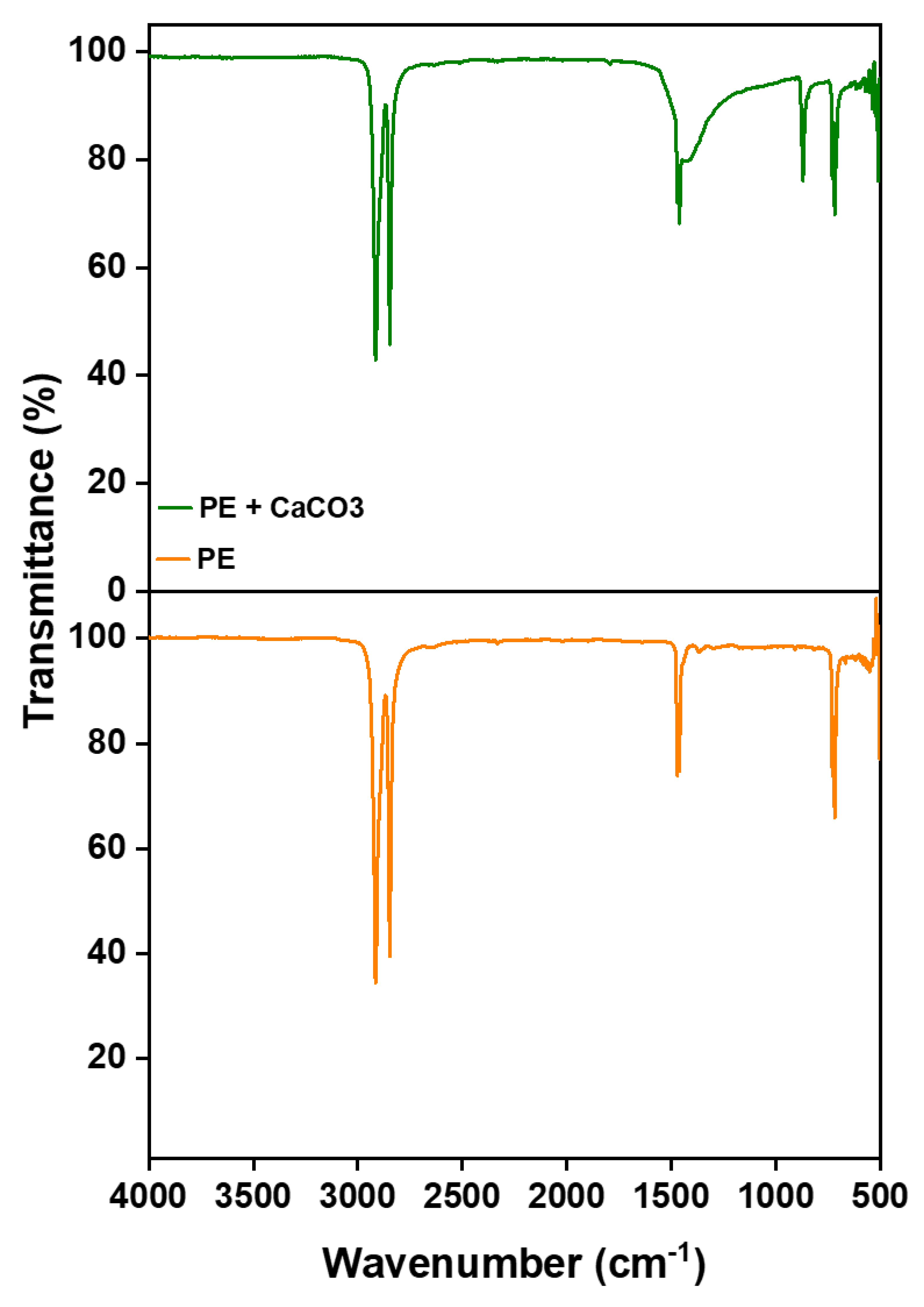
The incorporation of the filler into the polymer matrix is verified through Fourier Transform Infrared Spectroscopy (FTIR). This confirmation is achieved by comparing the spectra of the composite membrane with those of pure polyethylene, as illustrated in
Figure 1. The filler’s peaks are distinctly observed at around 1440 (asymmetric CO stretching), 873-898 cm⁻¹ (out-of-plane deformation of carbonate), and 712 ( OCO bending in-plane deformation vibrations of CaCO
3), respectively, confirming the presence of filler and its successful integration with the polymer [
23]. More importantly, the absence of new peaks in the FTIR spectrum suggests that there are no chemical changes occurring within the membrane. Instead, the interaction between the polymer and the filler is predominantly physical. This is supported by the observation that both PE and CaCO
3 retain their characteristic peaks, signifying the preservation of their individual chemical identities within the composite structure.
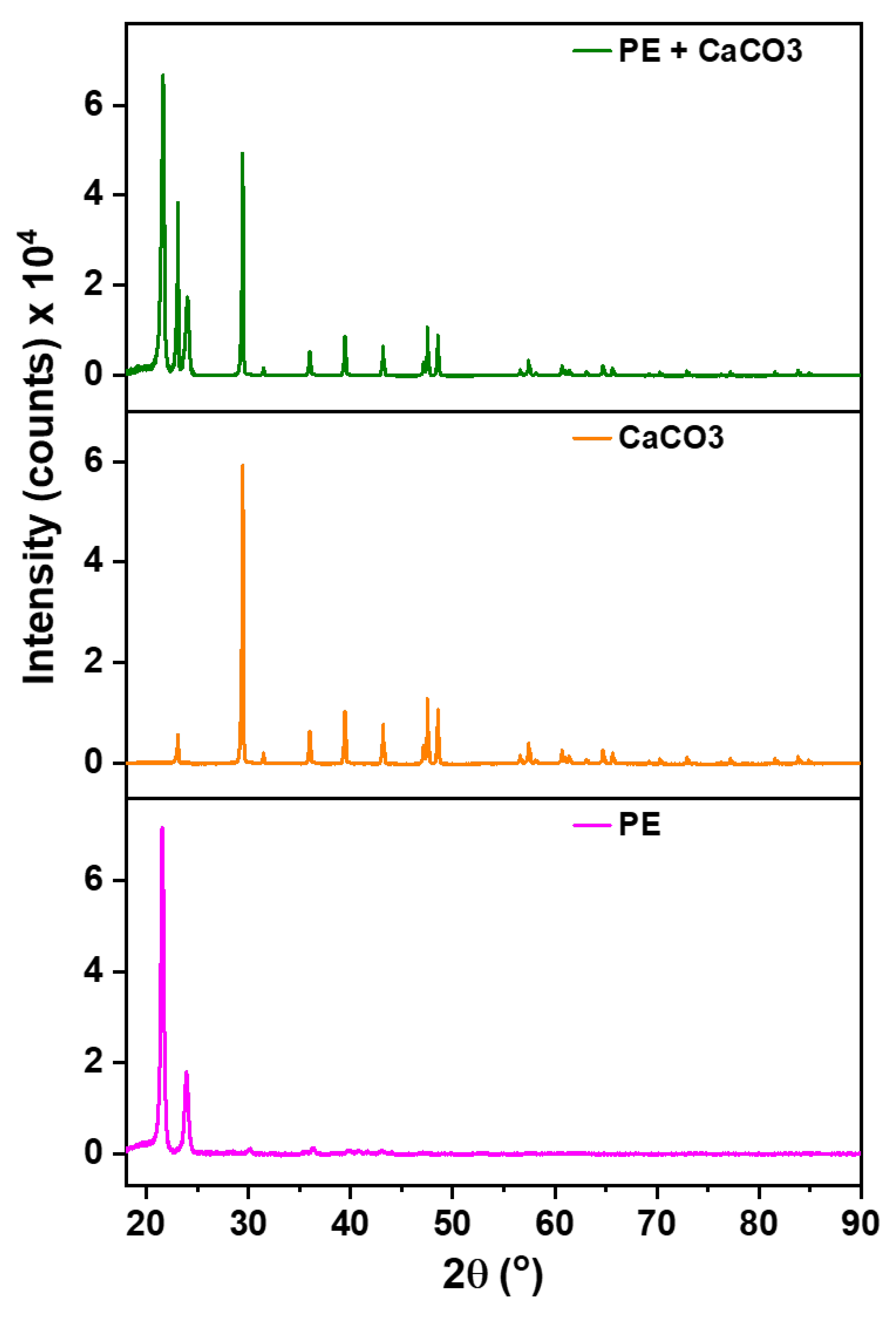
These results are further supported via XRD analysis,
Figure 2, to check the presence of filler within the membrane’s structure. The significance of this examination arises from the potential release of filler during synthesis, especially given its significantly higher density compared to the polymer. The polymer (PE) exhibits characteristics peaks at 22° and 24°, serving as reference points. All other discernible peaks in the XRD spectrum are attributed to the filler.
3.2. Thermal Behavior of the Composite
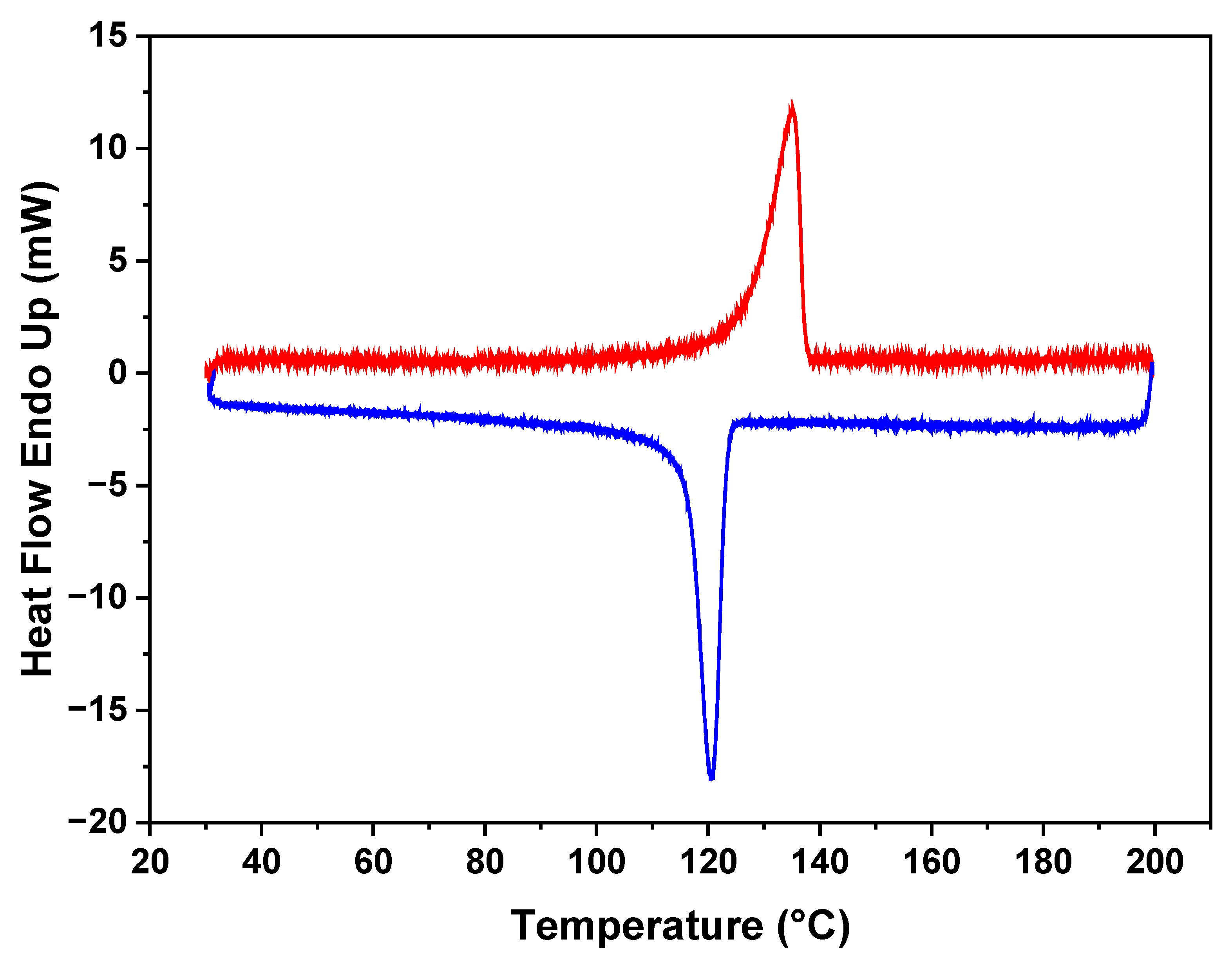
The DSC results in
Figure 3 reveal distinct thermal characteristics of the polymer in the membrane. It indicates a melting point for the polyethylene (PE) at 130 °C. Additionally, during the crystallization cooling phase, a melting point at 120 °C is observed, demonstrating the ability of the polymer to undergo reversible crystallization. Notably, the polymer maintains its melting behavior, and there are no discernible changes observed in subsequent analyses. This stability in the thermal behavior of the polymer within the membrane demonstrates its resilience and the preservation of its intrinsic properties.
3.3. Mechanical Strength and Filler Content Influence
In
Figure 4a, the impact of filler and stretching on membrane strength was examined. M1, stretched without filler, exhibited a higher strength, suggesting that the absence of filler contributes to enhanced membrane robustness. On the contrary, M2, containing filler, demonstrated increased break points and a consequent reduction in strength. Notably, M3, stretched 1.8 times, exhibited comparatively higher strength than M2. It is due to the alignment of polymeric chains in the direction of stretching. The developed membranes had significantly higher tensile strengths than commercially available membranes, such as Polyvinylidene Fluoride (PVDF) and Cellulose Acetate.
In
Figure 4b, the influence of filler amount on membrane strength was investigated. M3 has the highest strength as it contains the lowest filler content in a polymer-filler ratio of 10:1. Conversely, M6, with the highest filler content (ratio of 10:10), exhibited the lowest strength, due to the presence of more break points. Given its superior strength, M3 was selected for further characterizations and membrane performance tests.
Figure 4.
(a) The tensile strength of as-prepared membranes compared with commercial ones; (b) The effect of filler content on the strengths of the membranes.
Figure 4.
(a) The tensile strength of as-prepared membranes compared with commercial ones; (b) The effect of filler content on the strengths of the membranes.
3.4. Pore Structure and Water Flow Rate
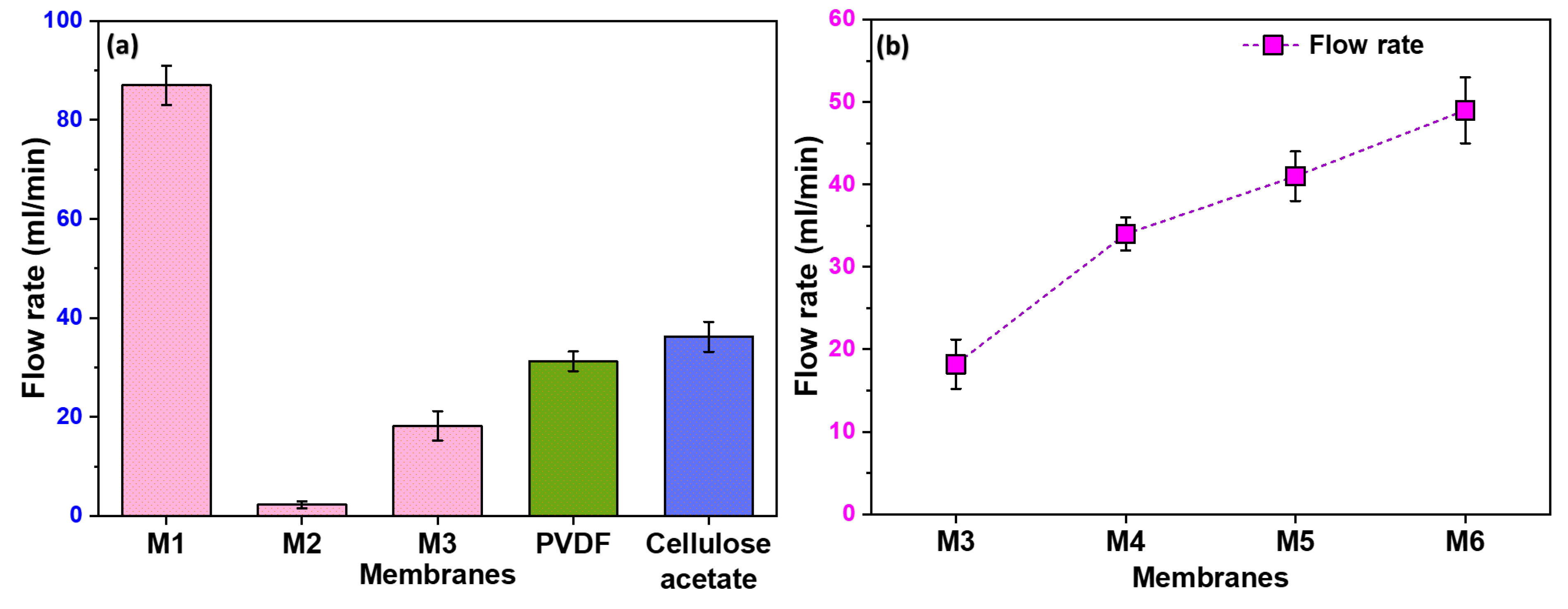
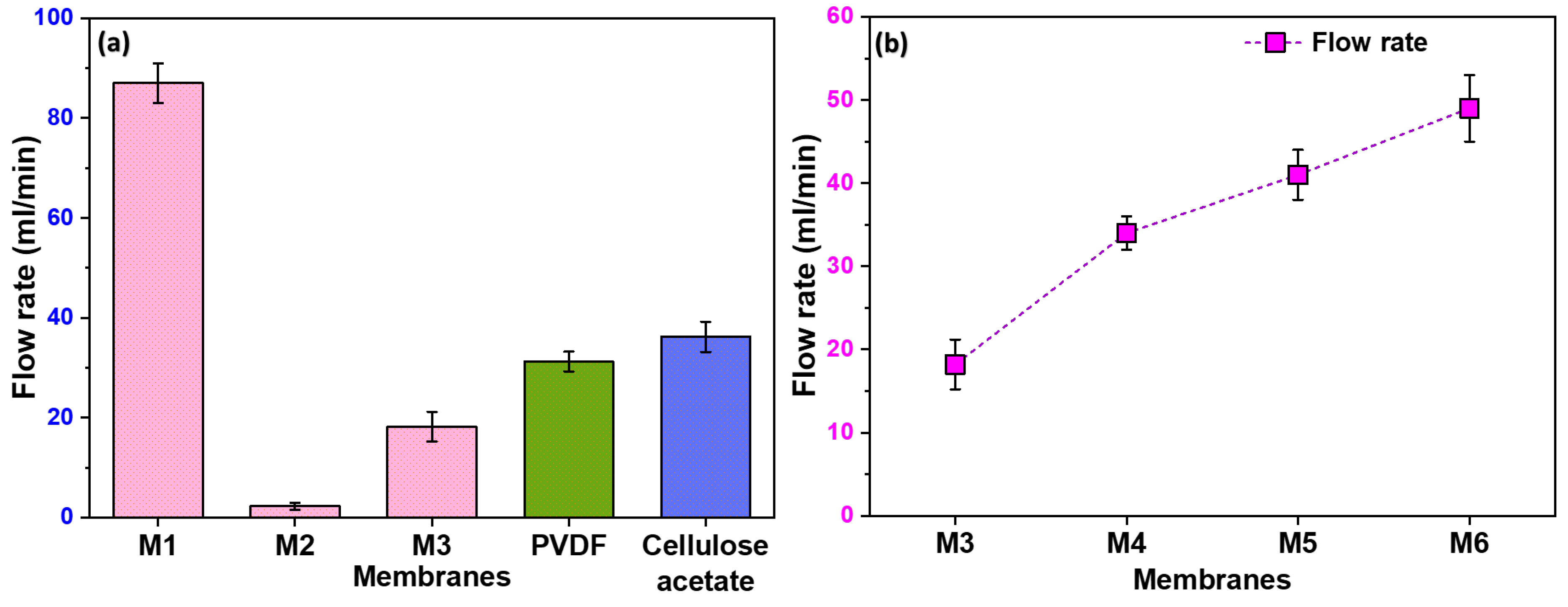
Figure 5a illustrates the notable variations in the flow rate among different membranes. M1 exhibited a high flow rate attributed to its non-uniform pores resulting from the stretching process. The randomness of these pores, with some being notably larger than others, contributed to the enhanced flow rate. On the contrary, M2, lacking any formed pores, showed a negligible flow rate. Moreover, M3 exhibits a higher flow rate compared to M2 due to the uniformity in pore size and distribution. However, as anticipated, its flow rate is lower than that of M1. The observed trend highlights the importance of pore uniformity in filtration efficiency, with M3 striking a balance between the extremes of M1 and M2.
3.5. Influence of Filler Content on Flow Rate
In
Figure 5b, we examined the effect of filler content on flow rate, with membranes M4 to M6 demonstrating significantly higher flow rates than M3. This improvement in flow is directly linked to the formation of pores at the polymer-filler interface. Consequently, it becomes evident that an increase in filler content corresponds to a higher pore formation, establishing a positive correlation between filler content and enhanced flow rates.
Figure 5.
Flow rate of distilled water through different membranes including commercially available PVDF and Cellulose acetate membranes; (b) The effect of filler content on the flow rate of the membranes.
Figure 5.
Flow rate of distilled water through different membranes including commercially available PVDF and Cellulose acetate membranes; (b) The effect of filler content on the flow rate of the membranes.
3.6. Surface Properties
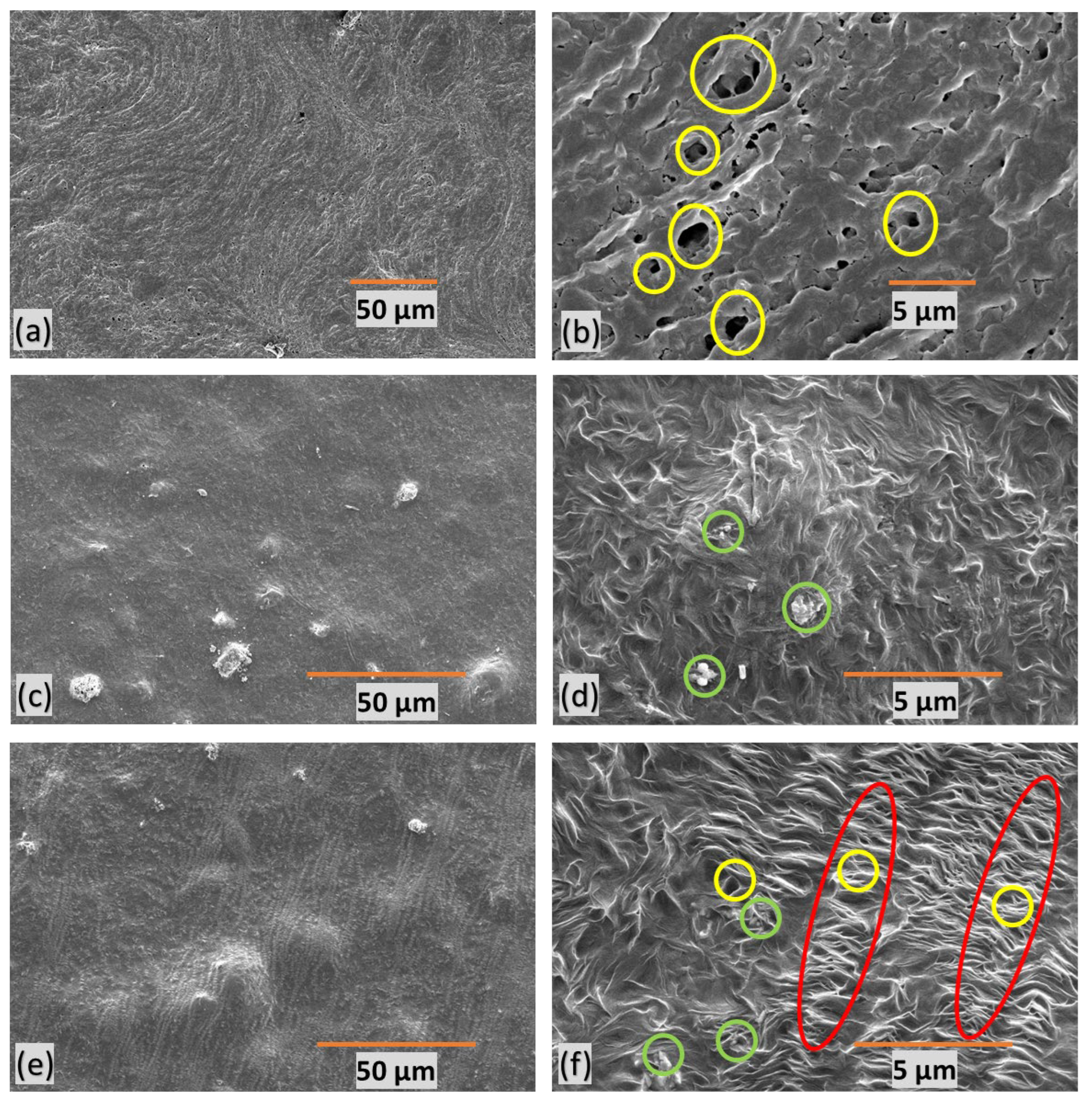
SEM of polymer-composite microfiltration membranes provide insights into their structural characteristics. Yellow circles represent pores, green circles denote filler particles, and red marks indicate stretched regions with micropores. M1 (Figures 6a-b) exhibits undesirable features, characterized by poor orientation, non-uniformity, and random distribution of large pores.
Figure 6(c-d) presents M2, revealing an absence of discernible pores due to the lack of stretching. This feature indicates the critical role stretching plays in pore formation within the membrane structure.
M3 (Figures 6e-f), on the other hand, displays a well-defined porous structure with a favorable orientation. It displays an average pore size of approximately 500nm. This suggests that uniform stretching contributes to a more consistent and controlled pore size within the membrane. These insights into membrane morphology are crucial for understanding the impact of stretching, orientation, and filler content on pore formation, ultimately influencing water filtration efficiency.
Figure 6.
SEM images of polymer-composite microfiltration membranes (a-b) M1, (c-d) M2 (e-f) M3.
Figure 6.
SEM images of polymer-composite microfiltration membranes (a-b) M1, (c-d) M2 (e-f) M3.
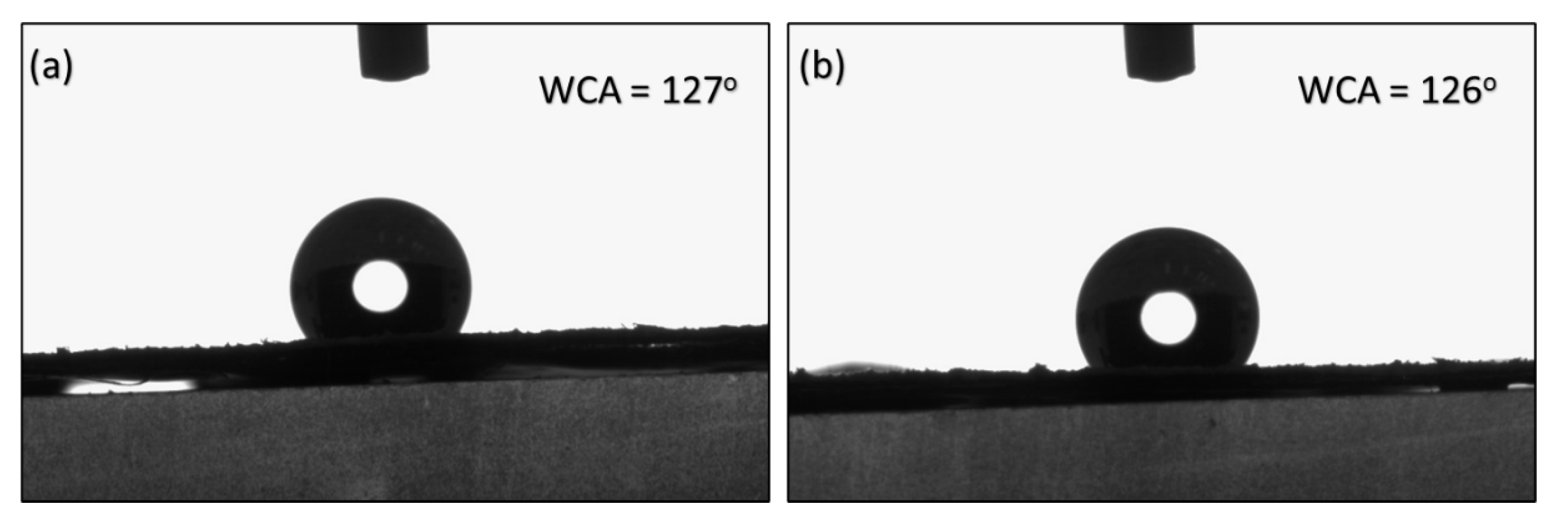
The contact angles of M2 and M3 are recorded at 127° and 126°, respectively and presented in
Figure 7. The results suggest that stretching did not significantly influence the surface properties of the membrane. Instead, the contact angles appeared to be predominantly dependent on the synthesis method employed prior to stretching.
3.7. Filtration and Membrane Regeneration
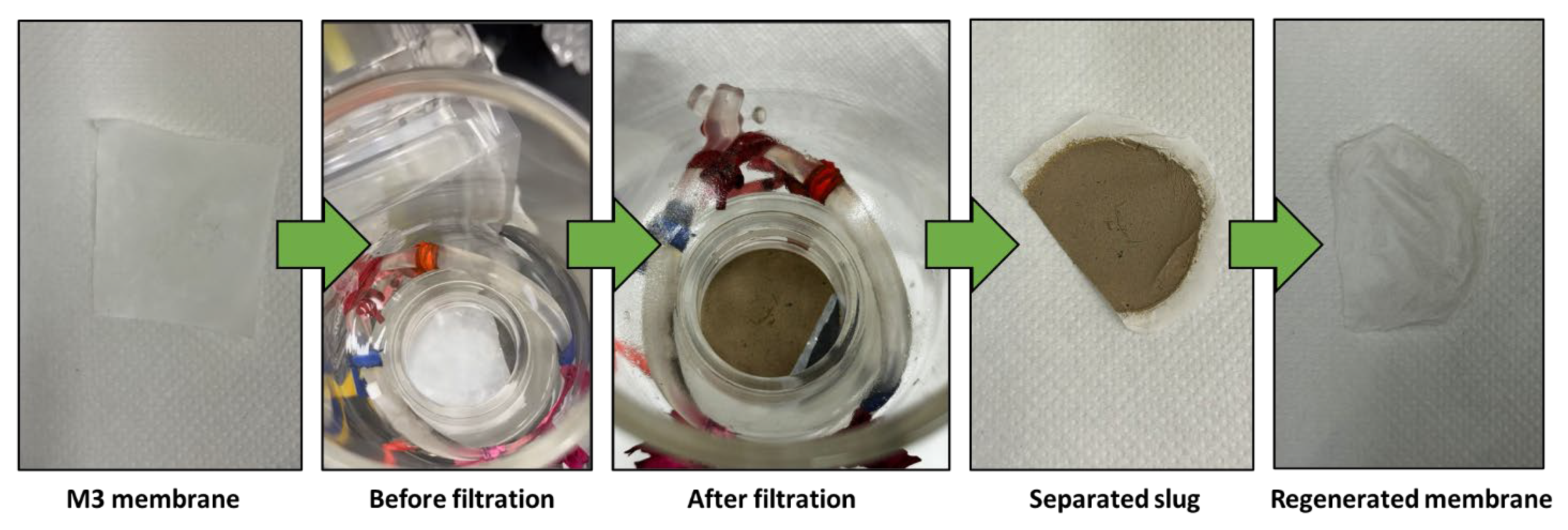
Figure 8 illustrates the separation outcomes of a mud-water emulsion as a representative example. The filtered water obtained is transparent compared to the original brownish-white feed emulsion before filtration.
Figure 9 provides the water filtration process using mud water, presenting a comparison before and after membrane filtration. It is noteworthy that the membranes possess the ability to undergo regeneration post-filtration, enabling their reuse across multiple cycles.
3.8. Filtration Efficiency Comparison and Recyclability
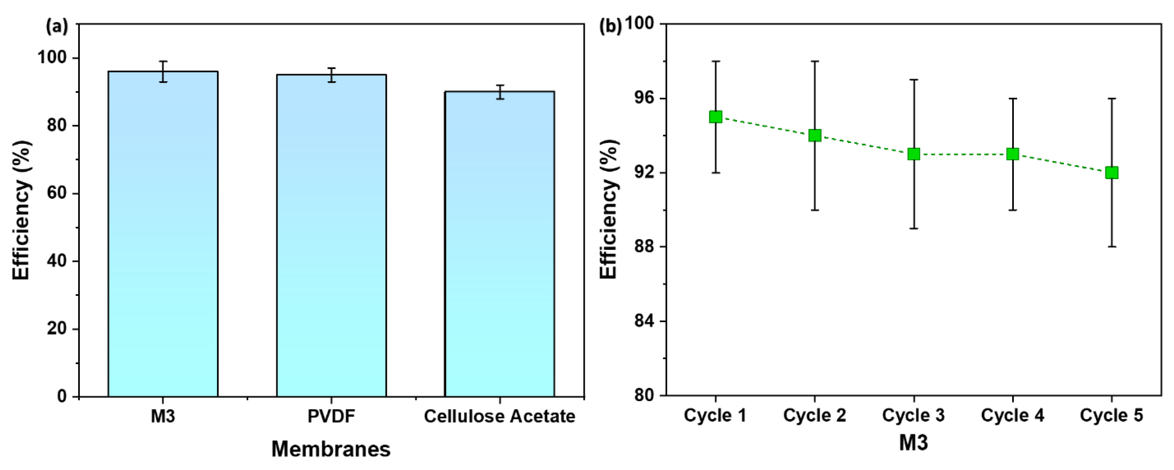
Figure 10a displays the efficiency of M3 in comparison to commercial membranes—PVDF and Cellulose Acetate. The M3 membrane showed a water filtration efficiency of 95 %, which is slightly higher than the PVDF membrane which demonstrated an efficiency of 93 %. On the other hand, Cellulose Acetate membrane illustrated the lowest efficiency—90 %.
The observed slightly higher filtration efficiency of the M3 membrane serves as a validation of its well-defined porous structure. The uniform and controlled pores in the membrane, resulting from the combination of spin-casting and uniaxial stretching, play a pivotal role in blocking mud particles while facilitating the permeation of water. This outcome aligns with the SEM images presented earlier, highlighting the importance of pore uniformity in achieving enhanced filtration efficiency.
Figure 10b provides recyclability of M3 with respect to water filtration efficiency. As evident, M3 is recyclable for at least 5 cycles with an efficiency of 92 %.
The superior filtration efficiency of the M3 membrane suggests its potential for practical applications in microfiltration technology. The ability to outperform commercial membranes, coupled with the advantages of reduced polymer requirements and shorter casting times associated with the spin-casting technique, positions the M3 membrane as a promising candidate for water treatment and purification processes.
Figure 10.
(a) A comparison of membrane efficiency with commercial membranes; (b) Recyclability of M3 with respect to water filtration efficiency.
Figure 10.
(a) A comparison of membrane efficiency with commercial membranes; (b) Recyclability of M3 with respect to water filtration efficiency.
4. Conclusion
The synthesis of microfiltration membranes from semi-crystalline polymers was investigated, employing spin-casting as an alternative to the extrusion–hot-pressing technique. An in-depth examination of various polymer-filler combinations, with and without stretching, is conducted on membranes designed for the efficient removal of suspended particles. Optimal conditions are identified, striking a crucial balance between pore structure and mechanical integrity.
The feasibility of this approach was demonstrated through a comparative analysis with commercial microfiltration membranes. Stretch-induced thin film composite membranes for semicrystalline polymers were evaluated in terms of flow rate and mechanical strength. The environmentally conscious approach, utilizing recycled HDPE, adds an extra layer of significance to the developed membrane synthesis process.
Acknowledgement
This publication was made possible by NPRP grant number NPRP12S-0325-190443 from the Qatar National Research Fund (a member of the Qatar Foundation). Open access funding is provided by Qatar National Library. The authors would also like to acknowledge Core Labs, Qatar Environment and Energy Research Institute, Hamad Bin Khalifa University, Qatar Foundation for providing assistance in SEM.
References
- D. S. Sholl and R. P. Lively, “Seven chemical separations to change the world,” Nature, vol. 532, no. 7600, pp. 435–437, Apr. 2016. [CrossRef]
- P. Marchetti, M. F. Jimenez Solomon, G. Szekely, and A. G. Livingston, “Molecular Separation with Organic Solvent Nanofiltration: A Critical Review,” Chem. Rev., vol. 114, no. 21, pp. 10735–10806, Nov. 2014. [CrossRef]
- X. Zhuang, L. Shi, K. Jia, B. Cheng, and W. Kang, “Solution blown nanofibrous membrane for microfiltration,” J. Memb. Sci., vol. 429, pp. 66–70, Feb. 2013. [CrossRef]
- H. Lin and Y. Ding, “Polymeric membranes: chemistry, physics, and applications,” J. Polym. Sci., vol. 58, no. 18, pp. 2433–2434, Sep. 2020. [CrossRef]
- S. Kuiper, C. J. . van Rijn, W. Nijdam, and M. . Elwenspoek, “Development and applications of very high flux microfiltration membranes,” J. Memb. Sci., vol. 150, no. 1, pp. 1–8, Nov. 1998. [CrossRef]
- J. Saleem, Z. K. B. Moghal, A. S. Luyt, R. A. Shakoor, and G. McKay, “Free-Standing Porous and Nonporous Polyethylene Thin Films Using Spin Coating: An Alternate to the Extrusion–Stretching Process,” ACS Appl. Polym. Mater., vol. 5, no. 3, pp. 2177–2184, Mar. 2023. [CrossRef]
- J. Saleem, M. Z. Khalid Baig, U. Bin Shahid, R. Luque, and G. McKay, “Mixed plastics waste valorization to high-added value products via thermally induced phase separation and spin-casting,” Green Energy Environ., Aug. 2023. [CrossRef]
- J. Saleem, Z. K. B. Moghal, and G. McKay, “Up-cycling plastic waste into swellable super-sorbents,” J. Hazard. Mater., vol. 453, p. 131356, Jul. 2023. [CrossRef]
- W. R. Hale, J. McGuire, I. D. Sand, and K. K. Dohrer, “Heat setting of stretched and microvoided PE/CaCO 3 films,” J. Appl. Polym. Sci., vol. 82, no. 10, pp. 2454–2471, Dec. 2001. [CrossRef]
- K. Kono, S. Mori, K. Miyasaka, and J. Tabuchi, “Polyethylene microporous membrane of ultra high molecular weight,” US Pat. 4,588,633, 1986.
- X. Zhang and G. Rumierz, “Biaxially oriented porous membranes, composites, and methods of manufacture and use,” US 2011/0223486 A1, 2011.
- L. Young-Keun, R. Jang-Weon, S. Jung-Moon, and J. Byoung-Cheon, “Microporous High Density Polyethylene film and Preparing method thereof,” US 2007/0218271 A1, 2007.
- S. Takeoka;, A. Saito;, H. Zhang;, and N. Takamizawa, “Ultra-thin polymer film and porous ultra-thin polymer film,” US 10,858,490 B2, 2020.
- C. Ho-seok, “Preparation Method for Free Standing Polymer Film with Through-pore Structured Micropores,” KR101714621B1, 2017.
- W. HERKENBERG, “Thin flexible sheet sorption material for the removal of oil from oil spills,” WO Pat. 1,991,008,347, pp. 1–7, 1991, Accessed: Aug. 22, 2013. [Online]. Available: http://patentscope.wipo.int/search/en/WO1991008347.
- W. HERKENBERG, “Thin flexible sheet sorption material for the removal of oil form oil spills,” EP 0507784 B1, pp. 1–7, 1991.
- T. Shinji, S. Akihiro, and T. ZhangNatsuki, “Ultra-thin polymer film and porous ultra-thin polymer film,” US 10,858,490 B2, 2018.
- J. Saleem, P. Gao, J. Barford, and G. McKay, “Development and characterization of novel composite membranes for fuel cell applications,” J. Mater. Chem. A, vol. 1, no. 45, pp. 14335–14343, 2013. [CrossRef]
- J. Saleem, C. Ning, J. Barford, and G. McKay, “Combating oil spill problem using plastic waste,” Waste Manag., vol. 44, 2015. [CrossRef]
- J. Saleem, A. Bazargan, J. Barford, and G. McKay, “Application of Strong Porous Polymer Sheets for Superior Oil Spill Recovery,” Chem. Eng. Technol., no. 3, pp. 482–488, 2015. [CrossRef]
- J. Saleem, A. Bazargan, J. Barford, and G. McKay, “Super-fast oil uptake using porous ultra-high molecular weight polyethylene sheets,” Polym. Adv. Technol., vol. 25, no. 10, pp. 1181–1185, Oct. 2014. [CrossRef]
- J. Saleem et al., “A facile energy-efficient approach to prepare super oil-sorbent thin films,” Energy Reports, vol. 9, pp. 40–45, May 2023. [CrossRef]
- Şirin, K.; Doǧan, F.; Balcan, M.; Kaya, “Effect of CaCO3 filler component on solid state decomposition kinetic of PP/LDPE/CaCO3 composites,” J. Macromol. Sci. Part A Pure Appl. Chem., vol. 46, 2009. [CrossRef]
|
Disclaimer/Publisher’s Note: The statements, opinions and data contained in all publications are solely those of the individual author(s) and contributor(s) and not of MDPI and/or the editor(s). MDPI and/or the editor(s) disclaim responsibility for any injury to people or property resulting from any ideas, methods, instructions or products referred to in the content. |
© 2024 by the authors. Licensee MDPI, Basel, Switzerland. This article is an open access article distributed under the terms and conditions of the Creative Commons Attribution (CC BY) license (http://creativecommons.org/licenses/by/4.0/).

