1. Introduction
In China’s energy structure, the thermal power equipment capacity has risen to 72% of the total installed capacity [
1]. These thermal power plants have been generating a lot of air pollution emissions, such as NO
x, SO
2, particulates and heavy metals. The particulates are mostly the inhalable particulate matters (PM
10), whose diameters are lower than 10 μm [
2]. Inhalable particulate is a major threat problem to human health [
3]. The main control technologies used presently in the power plants include the electrostatic precipitator (ESP) and the fabric filter (FF). Both of them have low collection efficiency for the fine particles (PM
2.5),whose diameters are lower than 2.5 μm [
4]. The results of the site tests from several power plants [
5,
6] show that the collection efficiency of the ESP and the FF is lower than 90% for the particles in the size range from 0.1 to 1 μm. Thus, some new technologies for the fine particle control have been proposed. Among them, the hybrid particulate collector (HPC) which combines the ESP and the FF together is widely used in China [
7]. In recent years, numerical simulation technology has been widely used in the design of the collectors [
8,
9,
10,
11].
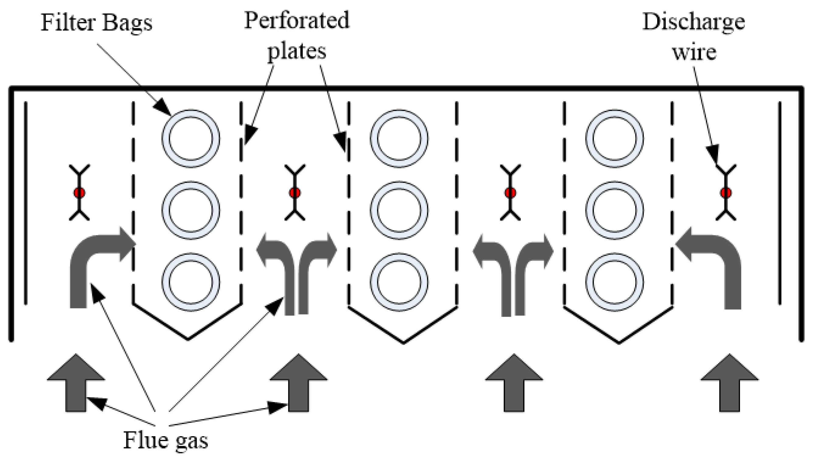
The advanced hybrid particulate collector (AHPC) is a new type precipitator [
12] (
Figure 1). The bags and the ESP are placed in the same housing, working synergically both in the particulate collection and in the dust cleaning. The AHPC provides ultrahigh collection efficiency, overcoming the problem of excessive fine-particle emission with conventional ESPs, and it solves the problem of re-entrainment and re-collection of dust in conventional baghouses. The experimental works show that the AHPC can achieve the particulate collection efficiencies of 99.99% for particle sizes from 0.01 to 50 µm. For economical consideration, the AHPC can work at a much higher air-to-cloth ratio with respect to the conventional fabric filters. The flue gas first flows into the ESP zone to remove the most particles (about 90% by mass), and then goes through the holes in the perforated plates into the fabric filtration zone to remove the left particles. Hence, the pressure drop through the fabric filters can be very low which means that the fabric filters have longer life.
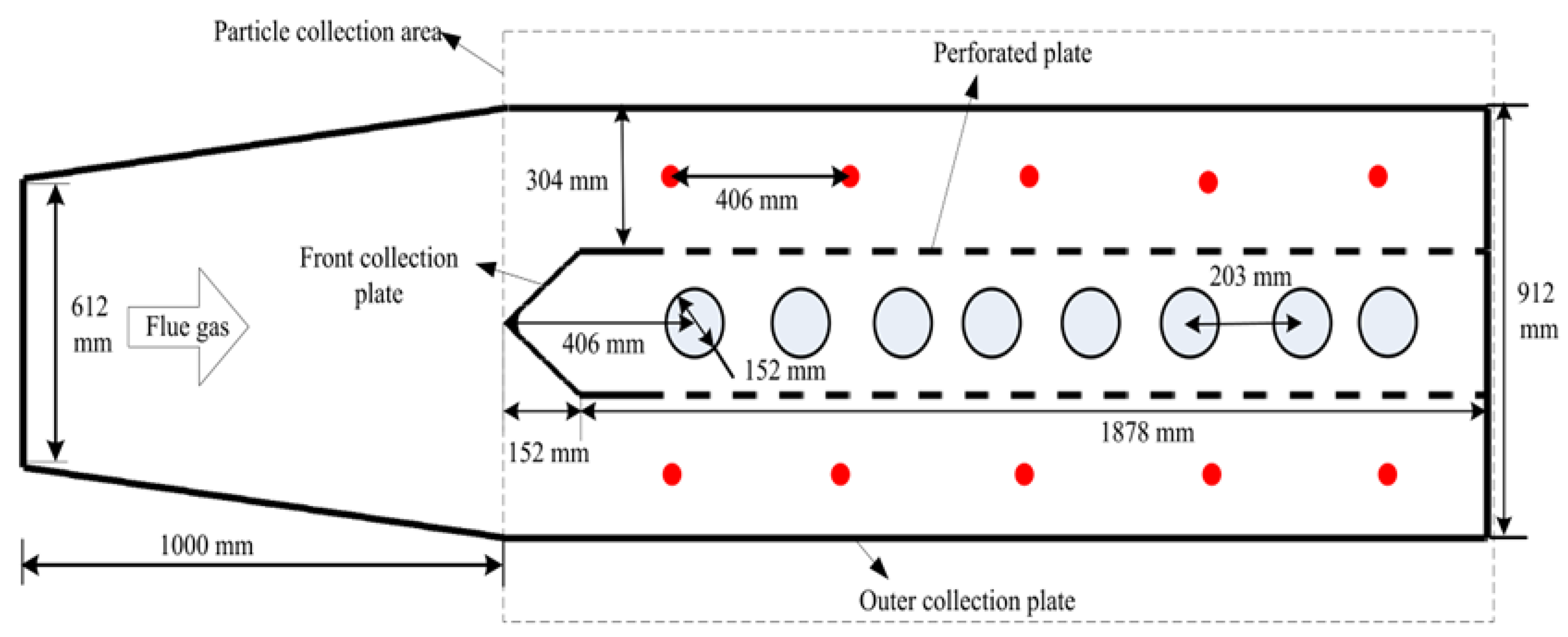
As the AHPC’s structure is very unique, its design needs some new criteria. Experimental work could solve some problems but not totally. Numerical method is a good way, as all the details can be obtained if the model is strong enough. In this work, an unsteady numerical model is used to investigate the particle deposition characteristics in a scale AHPC, which is shown in
Figure 2. The scale AHPC includes ten discharge wires, two perforated-plates with twenty-six staggered holes and eight bags (numbered 1 to 8 from left to right). In the simulation, the fluid field is modeled by using the unsteady time-averaged Navier-Stokes equations with the RNG
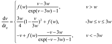
turbulent equations. The corona discharge field is analyzed by using a finite volume method. Particle dynamics are modeled by using the Lagrangian method with a field-diffusion combined charging model. For the bag filter, the pressure drop is divided to two parts: the pressure drop across the clean filter and the pressure across the cake on the bag surface. The pressure drop across the cake is related to the mass density of the deposited cake in the surface of bags.
2. Model Description
2.1. Electrostatic Precipitation Model
The physical fields in the AHPC include the fluid flow, the corona discharge, the particle charging, the particle dynamics and the filtration. The coupled effects between the fields should be considered too.
For the corona discharge, the equations can be expressed in dimensionless forms as follow [
13]:
where
is the electric potential (
),
the electric potential at the corona wire,
,
the space charge density at the corona wire (
),
the space charge density and
,
the air permittivity (
),
the current density (
),
the ion mobility (
),
the electric field (
).
As the pressure drop across the bag filter increase along with the filtration, the fluid flow is unsteady. Besides, the flow field is influenced by the electric field, namely the electro-hydrodynamic (EHD). This paper solves the full Navier-Stokes equations with the RNG turbulent equations [
14]:
where
is the fluid velocity (
),
is the fluid density (
), t is the time (s),
is the laminar viscosity (
),
is the turbulent viscosity (
),
is the fluid pressure (Pa),
is the electric body force (
),
is the acceleration of gravity (
).
The RNG turbulent model is derived from the application of a rigorous statistical technique to the instantaneous Navier-Stokes equations. It is suitable for the problems with high streamline curvatures [
15]. An unstructured finite volume method has been developed to solve this equation system [
16]. The fluid filed equations are solved by using the CFD package Fluent [
17]. The inlet boundary condition is the velocity-inlet and the outlet one is the outflow. The boundary condition of the walls is the wall function. The program for solving the corona discharge equations is linked to the Fluent by using the user defined functions (UDF).
The particle dynamics is modeled by using Lagrangian method [
18]. According to the Newton’s second law, the equation that describes the particle motion is written as:
where
is the local particle velocity,
is the local fluid velocity,
is the particle density,
is the particle diameter,
is the particle charge (
),
is the drag force coefficient,
is the gravity gradient.
The drag force coefficient
can be expressed as a function of the particle Reynolds number
as follows:
The turbulence has strong effect on the particle motion, namely the turbulence dispersion. In the present work, the discrete random walk (DRW) model [
19] is used.
The particle charge
in the Eq. (7) is calculated by using a field modified diffusion (FMD) model [
20]. The charging rate is expressed in the following dimensionless form:
where
is the fraction of the surface covered by the diffusive band:
where
(
) is the dimensionless particle charge,
(
) is the dimensionless electric field, and
is the dimensionless particle charging time,
is Boltzmann’s constant (
),
is the temperature (
),
is the charge on an electron (
),
is the particle dielectric constant,
is the local electric field (
),
is the space charge density (
).
The particle motion equation (7) is solved by using the Fluent program and the program for solving the particle charge equations (10)-(11) is linked to the Fluent by using the UDF.
2.2. Filtration Model
In the simulation, the particles will deposit on the bag surface to form a cake. There are two pressure drops: the one across the filter body and the one across the cake (
Figure 3):
where
is the total pressure drop,
the pressure drop across the cake and
the pressure drop across the filter.
The pressure drop across the filter body dependents only on the filtration velocity. And the pressure drop across the cake can be related to the filtration velocity according to the Kozeny-Carman equation [
21]:
where is the cake porosity, the particle density, dp the particle diameter, the filtration velocity, the air viscosity and the cake mass density.
The cake porosity
can be related to the particle diameter as [
22]:
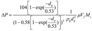
Thus, the pressure drop can be written as:
In the simulation, the bag filter is modeled as a porous media. And the cake mass density is calculated by using the total mass of the particles that reach the bag surface piece.
2.3. Model Validation
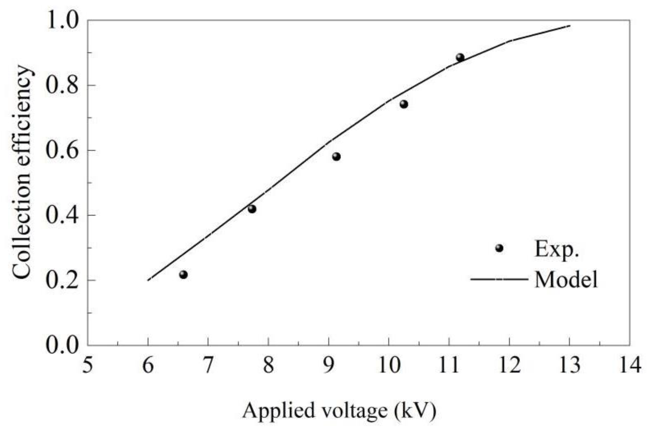
The particle collection efficiency data of Kihm (1987) was use to validate the electrostatic precipitation model [
23]. The model ESP consists of eight smooth round discharge wires with diameter 100 μm. The seeded droplets has a mass flux of about 7.49e-10 kg/s with uniform diameter 4 μm. The applied voltage is positive and ranged from approximately 6 kV to 14 kV. The gas velocity is 2 m/s.
Figure 4 shows the comparison between the model predictions and the experimental data. It proves that the model could be used to prediction the collection efficiency of the electrostatic precipitator.
3. Case Setup and Parameters
In the simulation, the mean filtration velocity is set to 3.6 m/min. Thus, the inlet gas velocity equal 0.37 m/s. To consider the turbulent dispersion, the inlet gas is thought to be the full developed turbulence flow. The outlet boundary condition is pressure-outlet.
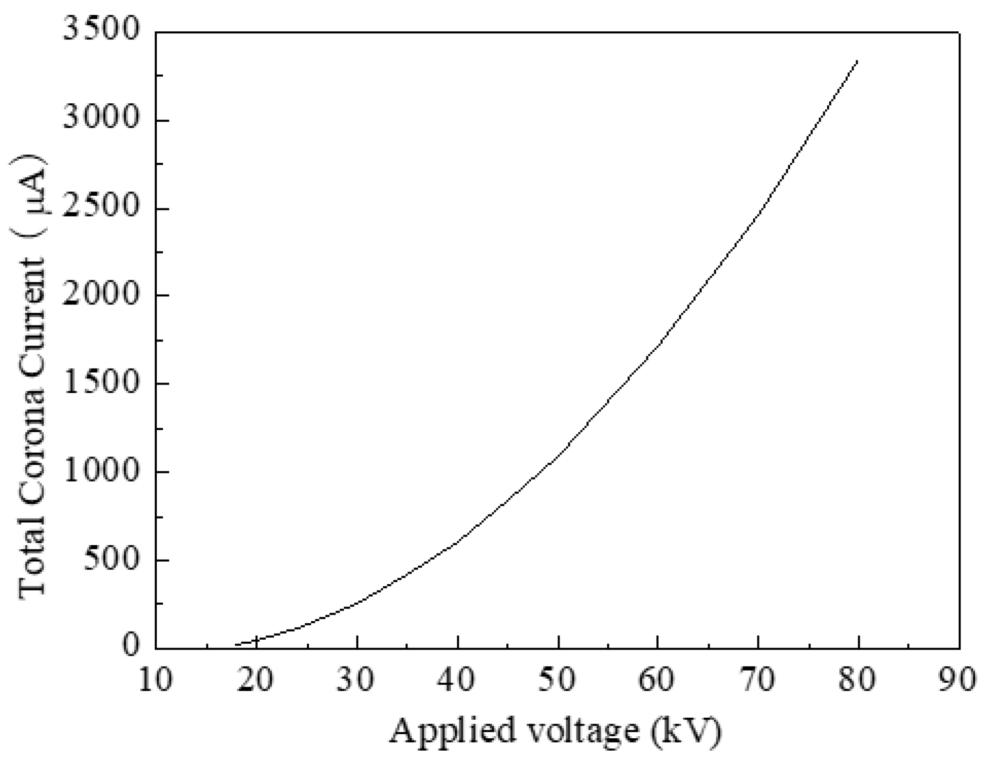
The scale AHPC has ten discharge wires. The wire diameter is 0.24 mm. The wire-wire space is 406 mm and the wire-plate space is 152 mm. Its current-voltage characteristic is calculated by using the semi-empirical theories, which have the following uniform formula:
where
i0 is the plate current density (mA/m
2),
V is the applied voltage (V),
kv is the geometry parameter, and
Vs is the corona onset voltage (V).
In this paper, the average values of two semi-empirical theories [
24,
25] are used. The current-voltage characteristic of the scale AHPC is shown in
Figure 5.
This work adopts the mono-disperse fly ash as the seed particle. The particle density is 2600 kg/m3. The particles are injected into the flow from the inlet face with the same velocity as the gas. The particle mass flux is set to 7.7×10⁻⁴kg/s. In the simulation, the time step is set to 1 second. The particles are injected into the flow once every second. Every time when the particles are injected, the pressure drops across the filter body and the cake are updated and the flow solver iterates until convergence. The total time of injecting particles is 600 second.
4. Results and Discussion
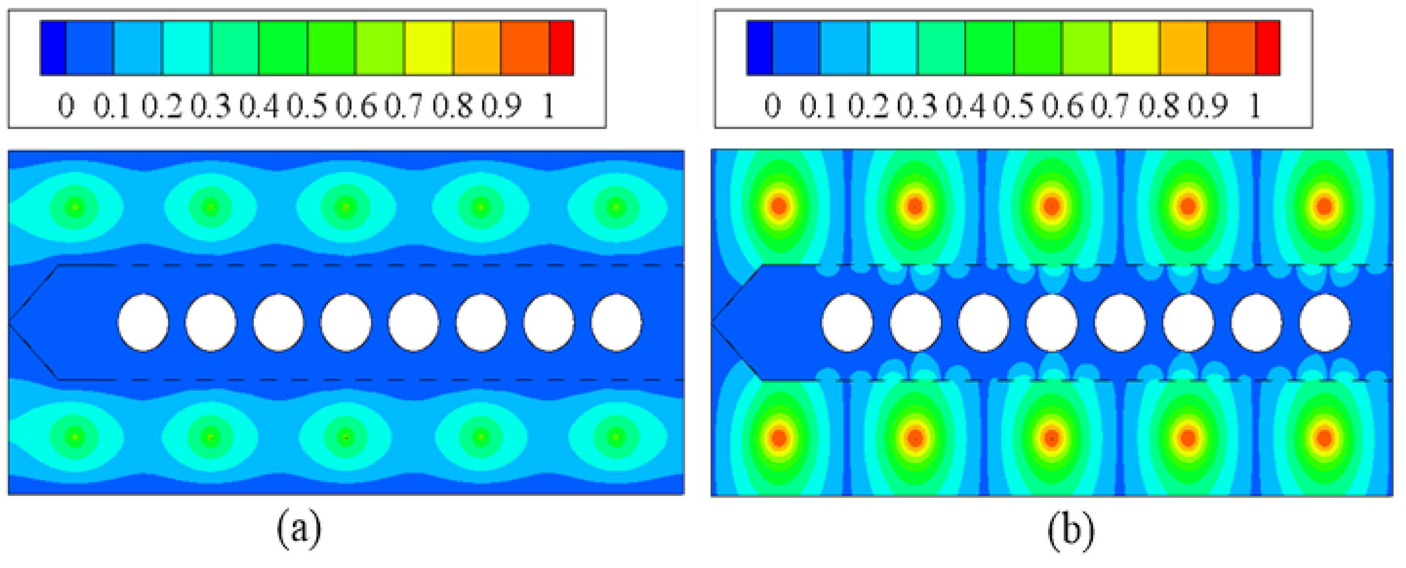
In the simulation, four types of particle size are considered: 0.1, 0.3, 1 and 3μm. The applied voltage is fixed at 40 kV.
Figure 6 shows the normalized voltage and the charge density distributions. The isolines of the voltage are orthogonal with that of the charge density. The results suggest that the perforated plates have good electric field shielding effects. Both the voltage and the charge density around the bags are very low. The charges are driven to the plates along the electric field lines. It is clear that part of charges reach the sides of the perforated plates facing the bags. Thus, it could be concluded that part of the charged particles will deposit those sides.
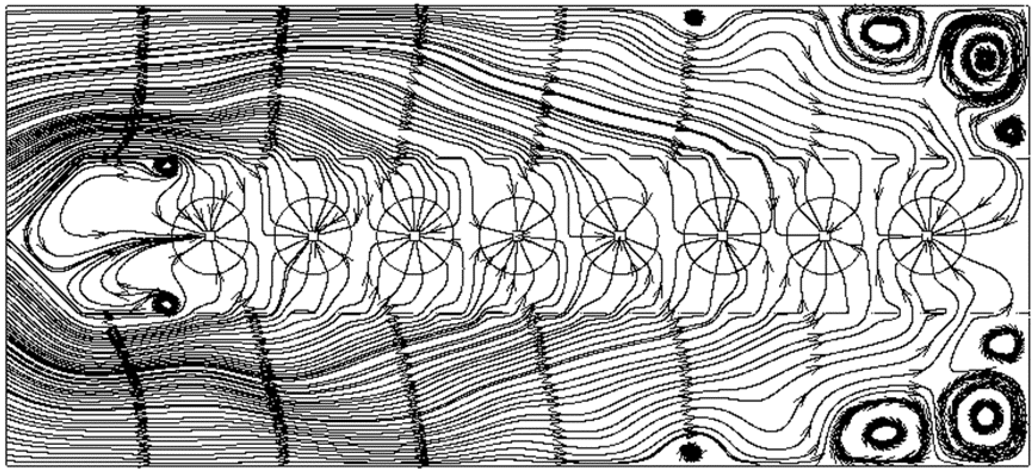
Figure 7 shows the stream line distribution in the scale AHPC without the particles. In each bag, one small square is added at the center. These squares are used to be the flow outlets. The gas flows into the electrostatic area firstly and then enters into the filtration area through the holes of the perforated plates. It is clear that the flow is influenced by the electric field. The streamlines have some wrinkles near the discharge wires. In most areas, the flow is irrotational. But in some places there are some vortexes. The first place is at the first hole of the perforated plate. The gas flows past this hole and then forms a vortex. The other places are at the tail area of the AHPC. The vortexes are not good for the collecting particles. The fine particles will follow the streamlines of the vortexes and are hard to deposit. Besides, the vortexes near the collecting plates will make the deposited particles re-entrain.
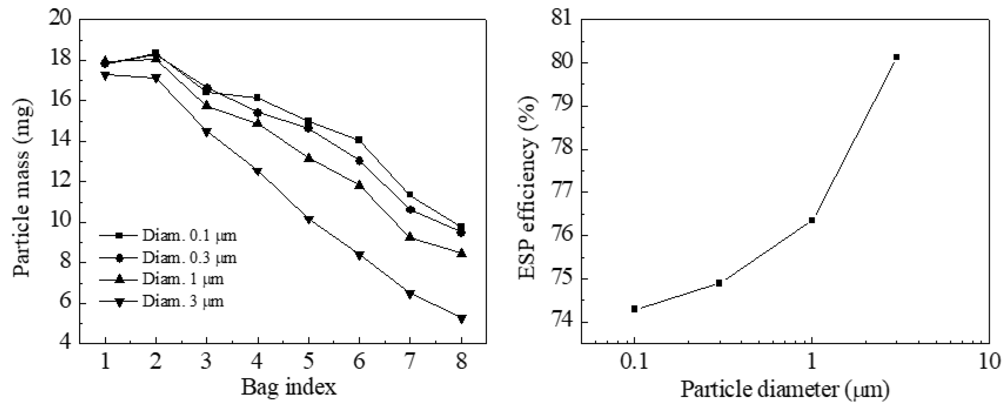
Figure 8 presents that the total mass of the deposited particles on the eight bags and the ESP collection efficiency. The results show that the particle mass decreases approximate linearly from the second bag from the left to the right-most bag. But the particle mass on the first two bags from the left are very close. As the eight bags have nearly the same surface filtration velocities, the pressure drops across the bags will be positive related to the deposited particle mass. Thus, higher particle mass results higher pressure drop. The bags with higher deposited particles will be more dangerous to be damaged. It is best to avoid this. One way is to design different hole size for the perforated plate. The hole size should get bigger from the left to the right. This will make more gas flow through the perforated plate from the right bags. The bigger particle size results lower deposited mass. It is also seen from the ESP collection efficiency, which increases approximate linearly with the particle diameter.
5. Conclusion
In this work, a numerical model for simulating the electrostatic fabric filter is presented. And the particle collection characteristics of a scale hybrid particulate collector are investigated. From the results of modeling, the following conclusions can be given:
1: The perforated plates have good electric field shielding effects.
2: Some vortexes exist at the area near the end of the hybrid particulate collector.
3: The particle size has no influence on the flow distribution between the bags. And the mass flow rate across each bag is very uniform.
4: From the first bag at the left to the last bag at the right, the deposited particle mass on the bag surface decreases. And the collection efficiency of the electrostatic zone increases approximate linearly with increasing the particle size.
Acknowledgments
This research has been supported by National Key Research and Development Plan of the Ministry of Science and Technology of China (Grant No. 2022YFB4100702) and National Science Foundation of China (Grant No.51878442).
References
- China’s National statistical bulletin, 2010.
- Zhang Chengfeng, Yao Qiang, Sun Junming. Characteristics of particulate matter from emissions of four typical coal-fired power plants in China. Fuel Processing Technology, 2005, 86: 757-768.
- Dockery, D.W.; Pope, C.A. Acute Respiratory Effects of Particulate Air Pollution. Annu. Rev. Public Health 1994, 15, 107–132. [Google Scholar] [CrossRef]
- Hinds W, C. Aerosol Technology: Properties, Behavior, and Measurement of Airborne Particles. Wiley, New York, 1999.
- Yi, H.; Guo, X.; Hao, J.; Duan, L.; Li, X. Characteristics of Inhalable Particulate Matter Concentration and Size Distribution from Power Plants in China. J. Air Waste Manag. Assoc. 2006, 56, 1243–1251. [Google Scholar] [CrossRef] [PubMed]
- Yi, H.; Hao, J.; Duan, L.; Tang, X.; Ning, P.; Li, X. Fine particle and trace element emissions from an anthracite coal-fired power plant equipped with a bag-house in China. Fuel 2008, 87, 2050–2057. [Google Scholar] [CrossRef]
- HUANG Wei, LIN Hong, ZHENG Kuizhao. The R&D and Application of Electrostatic-Fabric Organic Integrated Precipitator in China. The 11th International Conference on Electrostatic Precipitation, Hangzhou, China, 2008, pp. 464-467.
- Feng, Z.; Pan, W.; Zhang, H.; Cheng, X.; Long, Z.; Mo, J. Evaluation of the performance of an electrostatic enhanced air filter (EEAF) by a numerical method. Powder Technol. 2018, 327, 201–214. [Google Scholar] [CrossRef]
- Feng, Z.; Pan, W.; Wang, Y.; Long, Z. Modeling filtration performance of pleated fibrous filters by Eulerian-Markov method. Powder Technol. 2018, 340, 502–510. [Google Scholar] [CrossRef]
- Feng, Z.; Yang, J.; Zhang, J. Numerical optimization on newly developed electrostatic enhanced pleated air filters for efficient removal of airborne ultra-fine particles: Towards sustainable urban and built environment. Sustain. Cities Soc. 2019, 54, 102001. [Google Scholar] [CrossRef]
- Jiang, Y.; Yan, X. Numerical investigation of the performance of electrostatic precipitators with wet rope array as collection electrodes. Powder Technol. 2020, 366, 337–347. [Google Scholar] [CrossRef]
- Zhuang, Y, Stanley. J. Miller. Advance Hybrid Particulate Collector final topic report for phase III, 2001.
- McDonald, J.R.; Smith, W.B.; Iii, H.W.S.; Sparks, L.E. A mathematical model for calculating electrical conditions in wire-duct electrostatic precipitation devices. J. Appl. Phys. 1977, 48, 2231–2243. [Google Scholar] [CrossRef]
- Launder, B.E.; Spalding, D.B. The numerical computation of turbulent flows. Comput. Methods Appl. Mech. Eng. 1974, 3, 269–289. [Google Scholar] [CrossRef]
- Long, Z.; Yao, Q. Numerical simulation of the flow and the collection mechanism inside a scale hybrid particulate collector. Powder Technol. 2012, 215-216, 26–37. [Google Scholar] [CrossRef]
- Long Zhengwei, Yao Qiang, Song Qiang, Li Shuiqing. A second-order accurate finite volume method for computation of electrical conditions inside the wire-plate electrostatic precipitator on unstructured meshes. Journal of Electrostatics, 67 (4) 597-604, 2009.
- Fluent Inc. Fluent 6.0 user guide, 2001.
- Crowe, C.T.; Schwarzkopf, J.D.; Sommerfeld, M.; Tsuji, Y. Multiphase Flows with Droplets and Particles; CRC Press: Boca Raton, FL, USA, 2011. [Google Scholar]
- Morsi, S.A.; Alexander, A.J. An investigation of particle trajectories in two-phase flow systems. J. Fluid Mech. 1972, 55, 193–208. [Google Scholar] [CrossRef]
- Lawless, P.A. Particle charging bounds, symmetry relations and an analytic charging rate model for the continuum regime. J. Aerosol Sci., 1996, 27(2), 191–215.
- Neiva A, Leonardoa J. A procedure for calculating pressure drop during the build-up of dust filter cakes. Chemical Engineering and Processing, 2003, 42(6):495-501.
- Thomas, D.; Penicot, P.; Contal, P.; Leclerc, D.; Vendel, J. Clogging of fibrous filters by solid aerosol particles Experimental and modelling study. Chem. Eng. Sci. 2001, 56, 3549–3561. [Google Scholar] [CrossRef]
- Kihm, K. D. (1987). Effects of Nonuniformities on Particle Transport in Electrostatic Precipitators. Ph.D. dissertation, Department of Mechanical Engineering, Stanford University, Stanford, CA.
- Cooperman, G. A New Current-Voltage Relation for Duct Precipitators Valid for Low and High Current Densities. IEEE Trans. Ind. Appl. -17. [CrossRef]
- J. Böhm, Electrostatic Precipitators. Amsterdam: Elsevier Sci. Pub. Company, 1982.
|
Disclaimer/Publisher’s Note: The statements, opinions and data contained in all publications are solely those of the individual author(s) and contributor(s) and not of MDPI and/or the editor(s). MDPI and/or the editor(s) disclaim responsibility for any injury to people or property resulting from any ideas, methods, instructions or products referred to in the content. |
© 2024 by the authors. Licensee MDPI, Basel, Switzerland. This article is an open access article distributed under the terms and conditions of the Creative Commons Attribution (CC BY) license (https://creativecommons.org/licenses/by/4.0/).


