Submitted:
10 May 2024
Posted:
12 May 2024
You are already at the latest version
Abstract
Keywords:
1. Introduction
1.1 Influence of design and printing parameters on the mechanical properties in MEAM
1.2 Sinter shrinkage of MEAM parts
2. Materials and Methods
2.1 Preparation process of tensile specimens
2.2 Dimensional deviations and surface roughness
2.4 Tensile testing
3. Results and Discussion
3.1. Dimensional deviations
3.2. Surface roughness
3.3 Tensile testing
4. Conclusion
Author Contributions
Funding
Data Availability Statement
Acknowledgments
Conflicts of Interest
References
- Gonzalez-Gutierrez, J.; Godec, D.; Kukla, C.; Schlauf, T.; Burkhardt, C.; Holzer, C. SHAPING, DEBINDING AND SINTERING OF STEEL COMPONENTS VIA FUSED FILAMENT FABRICATION. 2017, 7.
- Ramazani, H.; Kami, A. Metal FDM, a New Extrusion-Based Additive Manufacturing Technology for Manufacturing of Metallic Parts: A Review. Prog. Addit. Manuf. 2022, 7, 609–626. [Google Scholar] [CrossRef]
- Rosnitschek, T.; Seefeldt, A.; Alber-Laukant, B.; Neumeyer, T.; Altstädt, V.; Tremmel, S. Correlations of Geometry and Infill Degree of Extrusion Additively Manufactured 316L Stainless Steel Components. Materials 2021, 14, 5173. [Google Scholar] [CrossRef] [PubMed]
- Sadaf, M.; Bragaglia, M.; Nanni, F. A Simple Route for Additive Manufacturing of 316L Stainless Steel via Fused Filament Fabrication. J. Manuf. Process. 2021, 67, 141–150. [Google Scholar] [CrossRef]
- Sadaf, M.; Bragaglia, M.; Slemenik Perše, L.; Nanni, F. Advancements in Metal Additive Manufacturing: A Comprehensive Review of Material Extrusion with Highly Filled Polymers. J. Manuf. Mater. Process. 2024, 8, 14. [Google Scholar] [CrossRef]
- Bouaziz, M.A.; Djouda, J.M.; Kauffmann, J.; Hild, F. Microscale Mechanical Characterization of 17-4PH Stainless Steel Fabricated by Atomic Diffusion Additive Manufacturing (ADAM). Procedia Struct. Integr. 2020, 28, 1039–1046. [Google Scholar] [CrossRef]
- Coatney, M.D.; Lawrence, B.D.; Henry, T.C.; Nataraj, L.; Hubbard, C. Fatigue Testing of Additively Manufactured 17-4PH Stainless Steel Samples with a Stress Concentration. In Fracture, Fatigue, Failure and Damage Evolution, Volume 3; Beese, A., Berke, R.B., Pataky, G., Hutchens, S., Eds.; Conference Proceedings of the Society for Experimental Mechanics Series; Springer International Publishing: Cham, 2023; pp. 53–60 ISBN 978-3-031-17466-7.
- Galati, M.; Minetola, P. Analysis of Density, Roughness, and Accuracy of the Atomic Diffusion Additive Manufacturing (ADAM) Process for Metal Parts. Materials 2019, 12, 4122. [Google Scholar] [CrossRef] [PubMed]
- Ghadimi, H.; Jirandehi, A.P.; Nemati, S.; Ding, H.; Garbie, A.; Raush, J.; Zeng, C.; Guo, S. Effects of Printing Layer Orientation on the High-Frequency Bending-Fatigue Life and Tensile Strength of Additively Manufactured 17-4 PH Stainless Steel. Materials 2023, 16, 469. [Google Scholar] [CrossRef] [PubMed]
- Gong, C.; Djouda, J.M.; Hmima, A.; Gaslain, F.; Chemkhi, M.; Maurer, T.; Panicaud, B. 2D Characterization at Submicron Scale of Crack Propagation of 17-4PH Parts Produced by Atomic Diffusion Additive Manufacturing (ADAM) Process. Procedia Struct. Integr. 2021, 34, 13–19. [Google Scholar] [CrossRef]
- Henry, T.C.; Morales, M.A.; Cole, D.P.; Shumeyko, C.M.; Riddick, J.C. Mechanical Behavior of 17-4 PH Stainless Steel Processed by Atomic Diffusion Additive Manufacturing. Int. J. Adv. Manuf. Technol. 2021, 114, 2103–2114. [Google Scholar] [CrossRef]
- Lavecchia, F.; Pellegrini, A.; Galantucci, L.M. Comparative Study on the Properties of 17-4 PH Stainless Steel Parts Made by Metal Fused Filament Fabrication Process and Atomic Diffusion Additive Manufacturing. Rapid Prototyp. J. 2023, 29, 393–407. [Google Scholar] [CrossRef]
- Lawrence, B.D.; Henry, T.C.; Phillips, F.; Riddick, J.; Kudzal, A. High-Cycle Tension-Tension Fatigue Performance of Additively Manufactured 17–4 PH Stainless Steel. Int. J. Adv. Manuf. Technol. 2023, 126, 777–786. [Google Scholar] [CrossRef]
- Opoz, T.T.; Burgess, A.; Ahuir-Torres, J.I.; Kotadia, H.R.; Tammas-Williams, S. The Effect of Surface Finish and Post-Processing on Mechanical Properties of 17-4 PH Stainless Steel Produced by the Atomic Diffusion Additive Manufacturing Process (ADAM). Int. J. Adv. Manuf. Technol. 2024, 130, 4053–4066. [Google Scholar] [CrossRef]
- Pellegrini, A.; Lavecchia, F.; Guerra, M.G.; Galantucci, L.M. Influence of Aging Treatments on 17–4 PH Stainless Steel Parts Realized Using Material Extrusion Additive Manufacturing Technologies. Int. J. Adv. Manuf. Technol. 2023, 126, 163–178. [Google Scholar] [CrossRef]
- Rodriguez, J.; Zuriarrain, A.; Madariaga, A.; Arrazola, P.J.; Dominguez, E.; Fraile, I.; Soler, D. Mechanical Properties and Fatigue Performance of 17-4 PH Stainless Steel Manufactured by Atomic Diffusion Additive Manufacturing Technology. J. Manuf. Mater. Process. 2023, 7, 172. [Google Scholar] [CrossRef]
- Timko, P.; Holubjak, J.; Bechný, V.; Novák, M.; Czán, A.; Czánová, T. Surface Analysis and Digitization of Components Manufactured by SLM and ADAM Additive Technologies. Manuf. Technol. 2023, 23, 127–134. [Google Scholar] [CrossRef]
- Agustina, D.; Putra, N. Investigation of Micro CT Based Method for Porosity Estimation of Sintered-Wick Heat Pipes. Heliyon 2023, 9, e13936. [Google Scholar] [CrossRef] [PubMed]
- Bordón, P.; Paz, R.; Monzón, M.D. Evaluation of the Performance of Atomic Diffusion Additive Manufacturing Electrodes in Electrical Discharge Machining. Materials 2022, 15, 5953. [Google Scholar] [CrossRef] [PubMed]
- Monzón, E.; Bordón, P.; Paz, R.; Monzón, M. Dimensional Characterization and Hybrid Manufacturing of Copper Parts Obtained by Atomic Diffusion Additive Manufacturing, and CNC Machining. Materials 2024, 17, 1437. [Google Scholar] [CrossRef]
- Wieczorek, L.; Katzwinkel, T.; Blüm, M.; Löwer, M.; Röttger, A. Supersolidus Liquid Phase Sintering and Heat Treatment on Atomic Diffusion Additive Manufacturing Produced Ledeburitic Cold Work Tool Steel*. HTM J. Heat Treat. Mater. 2022, 77, 269–283. [Google Scholar] [CrossRef]
- Kiswanto, G.; Kholil, A.; Istiyanto, J. Effect of Infill Pattern on Impact Toughness, Microstructure, and Surface Roughness of Inconel 625 Built via Filament-Based Material Extrusion Additive Manufacturing. J. Manuf. Mater. Process. 2023, 7, 114. [Google Scholar] [CrossRef]
- Khan, S.F.; Zakaria, H.; Chong, Y.L.; Saad, M.A.M.; Basaruddin, K. Effect of Infill on Tensile and Flexural Strength of 3D Printed PLA Parts. IOP Conf. Ser. Mater. Sci. Eng. 2018, 429, 012101. [Google Scholar] [CrossRef]
- Lalegani Dezaki, M.; Ariffin, M.K.A.M.; Serjouei, A.; Zolfagharian, A.; Hatami, S.; Bodaghi, M. Influence of Infill Patterns Generated by CAD and FDM 3D Printer on Surface Roughness and Tensile Strength Properties. Appl. Sci. 2021, 11, 7272. [Google Scholar] [CrossRef]
- Parab, S.; Zaveri, N. Investigating the Influence of Infill Pattern on the Compressive Strength of Fused Deposition Modelled PLA Parts. In Proceedings of International Conference on Intelligent Manufacturing and Automation; Vasudevan, H., Kottur, V.K.N., Raina, A.A., Eds.; Lecture Notes in Mechanical Engineering; Springer Singapore: Singapore, 2020; pp. 239–247 ISBN 9789811544842.
- Sadaf, M.; Cano, S.; Gonzalez-Gutierrez, J.; Bragaglia, M.; Schuschnigg, S.; Kukla, C.; Holzer, C.; Vály, L.; Kitzmantel, M.; Nanni, F. Influence of Binder Composition and Material Extrusion (MEX) Parameters on the 3D Printing of Highly Filled Copper Feedstocks. Polymers 2022, 14, 4962. [Google Scholar] [CrossRef] [PubMed]
- Galantucci, L.M.; Pellegrini, A.; Guerra, M.G.; Lavecchia, F. 3D Printing of Parts Using Metal Extrusion: An Overview of Shaping Debinding and Sintering Technology. Adv. Technol. Mater. 2022, 47, 25–32. [Google Scholar] [CrossRef]
- Suwanpreecha, C.; Manonukul, A. A Review on Material Extrusion Additive Manufacturing of Metal and How It Compares with Metal Injection Moulding. Metals 2022, 12, 429. [Google Scholar] [CrossRef]
- Rosnitschek, T.; Hueter, F.; Alber-Laukant, B. FEM-Based Modelling of Elastic Properties and Anisotropic Sinter Shrinkage of Metal EAM. Int. J. Simul. Model. 2020, 19, 197–208. [Google Scholar] [CrossRef]
- Wang, F.; You, S.; Jiang, D.; Ning, F. Study on Sintering Mechanism for Extrusion-Based Additive Manufacturing of Stainless Steel through Molecular Dynamics Simulation. Addit. Manuf. 2022, 58, 102991. [Google Scholar] [CrossRef]
- Kurose, T.; Abe, Y.; Santos, M.V.A.; Kanaya, Y.; Ishigami, A.; Tanaka, S.; Ito, H. Influence of the Layer Directions on the Properties of 316L Stainless Steel Parts Fabricated through Fused Deposition of Metals. Materials 2020, 13, 2493. [Google Scholar] [CrossRef]
- Damon, J.; Dietrich, S.; Gorantla, S.; Popp, U.; Okolo, B.; Schulze, V. Process Porosity and Mechanical Performance of Fused Filament Fabricated 316L Stainless Steel. Rapid Prototyp. J. 2019, 25, 1319–1327. [Google Scholar] [CrossRef]
- Tosto, C.; Tirillò, J.; Sarasini, F.; Cicala, G. Hybrid Metal/Polymer Filaments for Fused Filament Fabrication (FFF) to Print Metal Parts. Appl. Sci. 2021, 11, 1444. [Google Scholar] [CrossRef]
- Gonzalez-Gutierrez, J.; Cano, S.; Ecker, J.V.; Kitzmantel, M.; Arbeiter, F.; Kukla, C.; Holzer, C. Bending Properties of Lightweight Copper Specimens with Different Infill Patterns Produced by Material Extrusion Additive Manufacturing, Solvent Debinding and Sintering. Appl. Sci. 2021, 11, 7262. [Google Scholar] [CrossRef]
- Gonzalez-Gutierrez, J.; Cano, S.; Schuschnigg, S.; Kukla, C.; Sapkota, J.; Holzer, C. Additive Manufacturing of Metallic and Ceramic Components by the Material Extrusion of Highly-Filled Polymers: A Review and Future Perspectives. Materials 2018, 11, 840. [Google Scholar] [CrossRef] [PubMed]
- Thompson, Y.; Gonzalez-Gutierrez, J.; Kukla, C.; Felfer, P. Fused Filament Fabrication, Debinding and Sintering as a Low Cost Additive Manufacturing Method of 316L Stainless Steel. Addit. Manuf. 2019, 30, 100861. [Google Scholar] [CrossRef]
- Rane, K.; Strano, M. A Comprehensive Review of Extrusion-Based Additive Manufacturing Processes for Rapid Production of Metallic and Ceramic Parts. Adv. Manuf. 2019, 7, 155–173. [Google Scholar] [CrossRef]
- Singh, G.; Missiaen, J.-M.; Bouvard, D.; Chaix, J.-M. Additive Manufacturing of 17–4 PH Steel Using Metal Injection Molding Feedstock: Analysis of 3D Extrusion Printing, Debinding and Sintering. Addit. Manuf. 2021, 47, 102287. [Google Scholar] [CrossRef]
- Abe, Y.; Kurose, T.; Santos, M.; Kanaya, Y.; Ishigami, A.; Tanaka, S.; Ito, H. Effect of Layer Directions on Internal Structures and Tensile Properties of 17-4PH Stainless Steel Parts Fabricated by Fused Deposition of Metals. Materials 2021, 14, 243. [Google Scholar] [CrossRef]
- Obadimu, S.O.; Kourousis, K.I. Shrinkage Behaviour of Material Extrusion Steel 316L: Influence of Primary 3D Printing Parameters. Rapid Prototyp. J. 2022, 28, 92–101. [Google Scholar] [CrossRef]
- Rosnitschek, T.; Glamsch, J.; Lange, C.; Alber-Laukant, B.; Rieg, F. An Automated Open-Source Approach for Debinding Simulation in Metal Extrusion Additive Manufacturing. Designs 2021, 5, 2. [Google Scholar] [CrossRef]
- Zhang, Z.; Fidan, I. Machine Learning-Based Void Percentage Analysis of Components Fabricated with the Low-Cost Metal Material Extrusion Process. Materials 2022, 15, 4292. [Google Scholar] [CrossRef]
- Zhang, Z.; Femi-Oyetoro, J.; Fidan, I.; Ismail, M.; Allen, M. Prediction of Dimensional Changes of Low-Cost Metal Material Extrusion Fabricated Parts Using Machine Learning Techniques. Metals 2021, 11, 690. [Google Scholar] [CrossRef]
- Markforged Inc. Inconel 625 Filament Datasheet.
- Deutsches Institut für Normung DIN EN ISO 6892-1:2020-06, Metallische Werkstoffe - Zugversuch - Teil 1: Prüfverfahren Bei Raumtemperatur (ISO_6892-1:2019); Deutsche Fassung EN ISO 6892-1:2019; Beuth Verlag GmbH.
- Alsoufi, M.S.; Elsayed, A.E. Surface Roughness Quality and Dimensional Accuracy—A Comprehensive Analysis of 100% Infill Printed Parts Fabricated by a Personal/Desktop Cost-Effective FDM 3D Printer. Mater. Sci. Appl. 2018, 09, 11–40. [Google Scholar] [CrossRef]
- Alsoufi, M.; Elsayed, A. Quantitative Analysis of 0% Infill Density Surface Profile of Printed Part Fabricated by Personal FDM 3D Printer. Int. J. Eng. Technol. 2018, 7, 44. [Google Scholar] [CrossRef]
- Jasim, M.; Abbas, T.; Huayier, A. The Effect of Infill Pattern on Tensile Strength of PLA Material in Fused Deposition Modeling (FDM) Process. Eng. Technol. J. 2022, 40, 1–8. [Google Scholar] [CrossRef]
- Eryildiz, M. Effect of Build Orientation on Mechanical Behaviour and Build Time of FDM 3D-Printed PLA Parts: An Experimental Investigation. Eur. Mech. Sci. 2021, 5, 116–120. [Google Scholar] [CrossRef]
- Wang, S.; Ma, Y.; Deng, Z.; Zhang, S.; Cai, J. Effects of Fused Deposition Modeling Process Parameters on Tensile, Dynamic Mechanical Properties of 3D Printed Polylactic Acid Materials. Polym. Test. 2020, 86, 106483. [Google Scholar] [CrossRef]
- Corapi, D.; Morettini, G.; Pascoletti, G.; Zitelli, C. Characterization of a Polylactic Acid (PLA) Produced by Fused Deposition Modeling (FDM) Technology. Procedia Struct. Integr. 2019, 24, 289–295. [Google Scholar] [CrossRef]
- Hanon, M.M.; Alshammas, Y.; Zsidai, L. Effect of Print Orientation and Bronze Existence on Tribological and Mechanical Properties of 3D-Printed Bronze/PLA Composite. Int. J. Adv. Manuf. Technol. 2020, 108, 553–570. [Google Scholar] [CrossRef]
- Zaldivar, R.J.; Witkin, D.B.; McLouth, T.; Patel, D.N.; Schmitt, K.; Nokes, J.P. Influence of Processing and Orientation Print Effects on the Mechanical and Thermal Behavior of 3D-Printed ULTEM® 9085 Material. Addit. Manuf. 2017, 13, 71–80. [Google Scholar] [CrossRef]
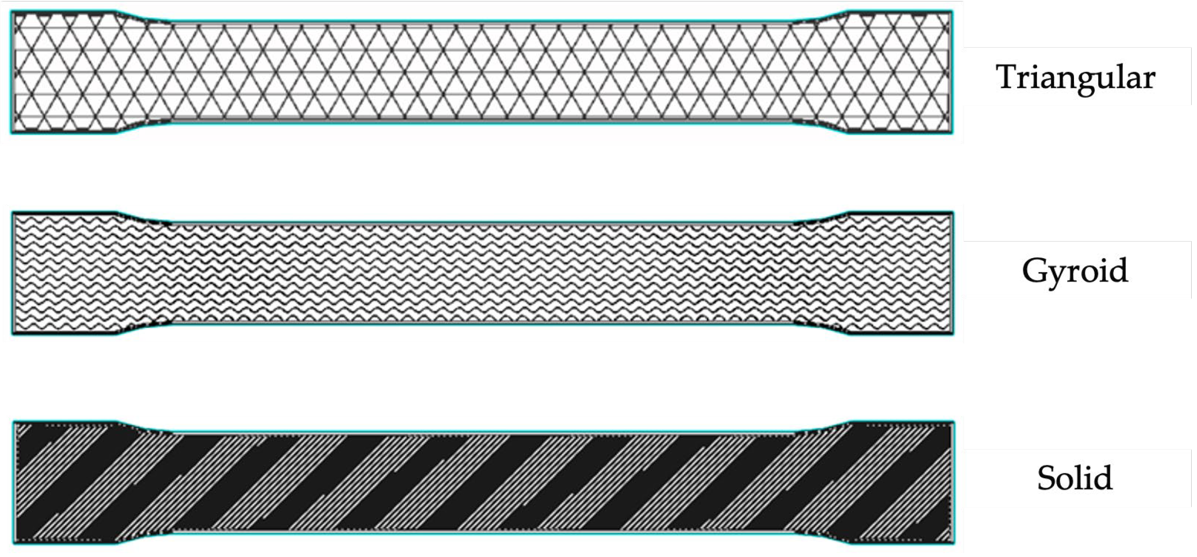
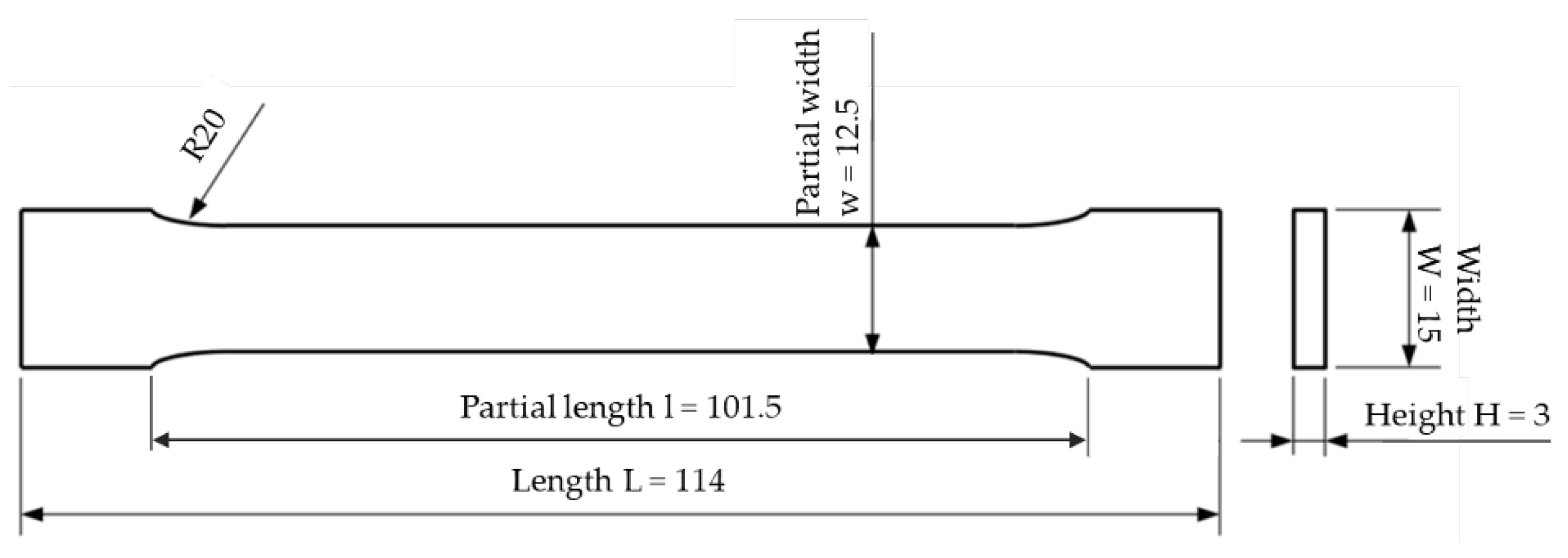


|
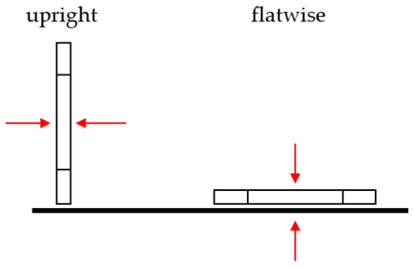
Solid flatwise |
Solid upright |
Gyroid flatwise |
Gyroid upright |
Triangular flatwise |
Triangular upright |
|
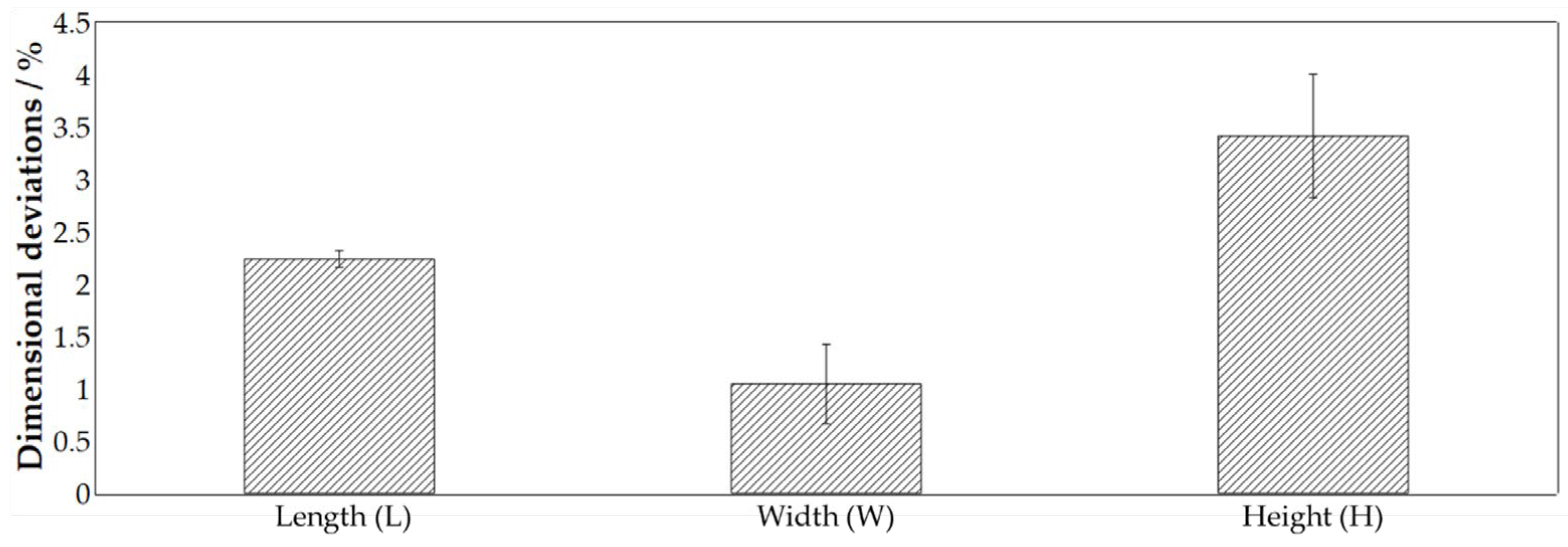
| As printed (mm) | 137.2 x 18.1 x 3.6 | 135.8 x 18.1 x 3.6 | 137.2 x 18.1 x 3.6 | 135.8 x 18.1 x 3.6 | 137.2 x 18.1 x 3.6 | 135.8 x 18.1 x 3.6 |
| As sintered (mm) | 114.0 x 15.0 x 3.0 | 114.0 x 15.0 x 3.0 | 114.0 x 15.0 x 3.0 | 114.0 x 15.0 x 3.0 | 114.0 x 15.0 x 3.0 | 114.0 x 15.0 x 3.0 |
| Layer height (mm) | 0.125 | 0.125 | 0.125 | 0.125 | 0.125 | 0.125 |
| Roof and floor layer | - | - | 4 | 4 | 4 | 4 |
| Wall layers | 2 | 2 | 4 | 4 | 4 | 4 |
| Nozzle temperature | 220 °C | 220 °C | 220 °C | 220 °C | 220 °C | 220 °C |
| Bed temperature | 112 °C | 112 °C | 112 °C | 112 °C | 112 °C | 112 °C |
| Chamber temperature | 48 ° | 48 ° | 48 ° | 48 ° | 48 ° | 48 ° |
| Print time | 2h 37 min | 5h 30 min | 2h 22min | 5h 24 min | 2h 5min | 5h 5min |
| Wash time | 12 h | 12 h | 4 h | 4 h | 4 h | 4 h |
| Dry time | 4 h | 4 h | 4 h | 4 h | 1 h | 1 h |
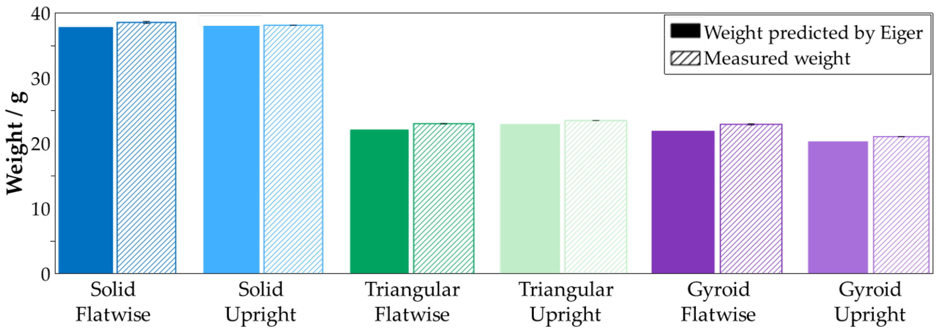
| Printed part mass (g) | 42.47 | 50.28 | 24.61 | 29.74 | 24.82 | 32.74 |
| Final part mass (g) | 37.83 | 38.57 | 21.91 | 20.27 | 22.1 | 22.94 |
| Metal volume (cm3) | 7.74 | 9.15 | 4.48 | 5.41 | 4.52 | 5.96 |
| Configuration | out | Young’s modulus in GPa | Yield strength in MPa | Ultimate tensile strength in MPa | Strain at break in % |
|---|---|---|---|---|---|
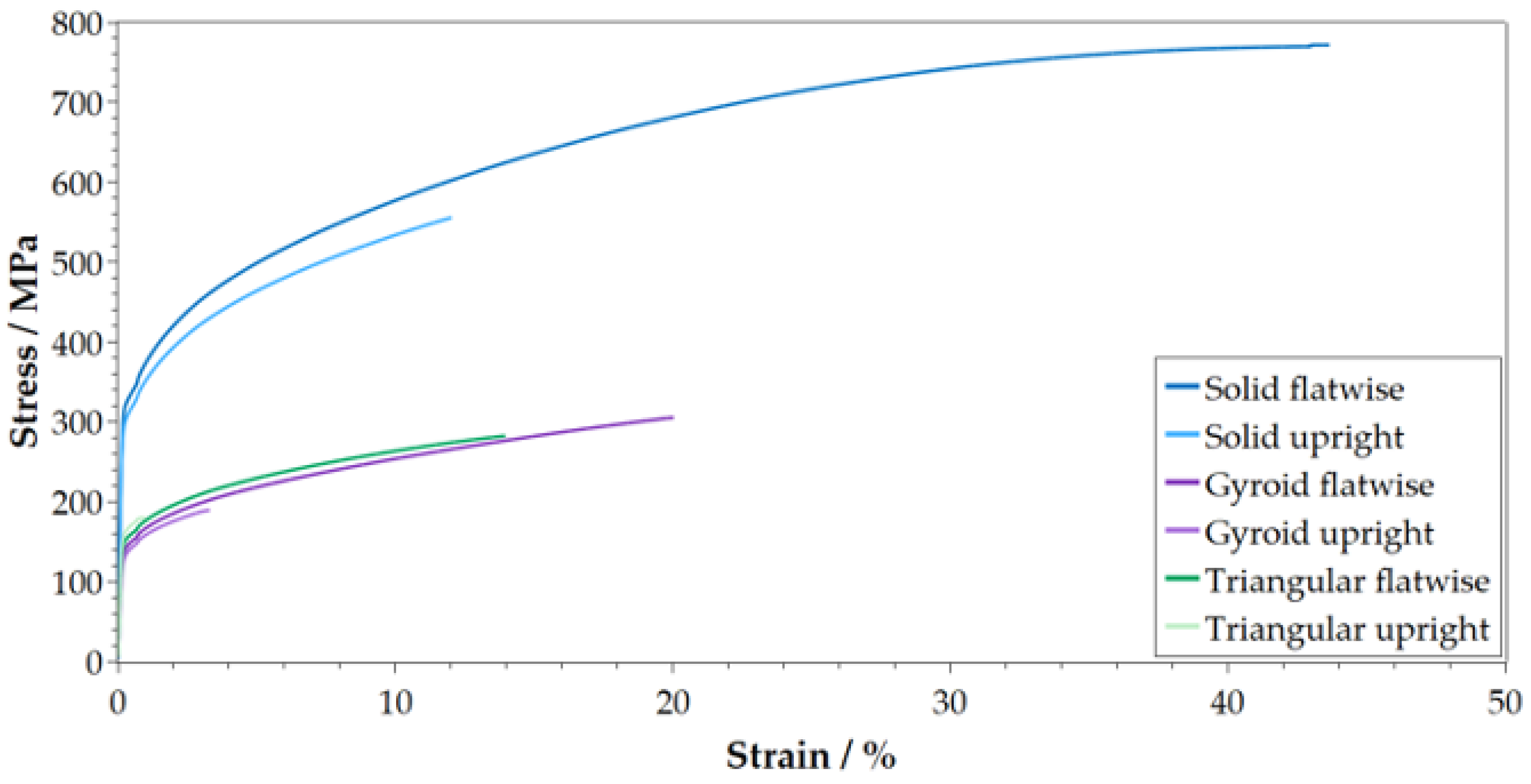
| Solid flatwise | 1 | 194.75 ± 7.01 | 327.5 ± 1.80 | 769.75 ± 1.48 | 46.31 ± 0.82 |
| Solid upright | 1 | 202.25 ± 26.6 | 308.25 ± 1.64 | 572.75 ± 10.69 | 14.06 ± 1.32 |
| Gyroid flatwise | 3 | 87.50 ± 2.50 | 145.5 ± 0.5 | 308.00 ± 2.00 | 20.62 ± 0.50 |
| Gyroid upright | 3 | 77.00 ± 4.00 | 138.00 ± 1.00 | 194.00 ± 5.00 | 4.33 ± 0.70 |
| Triangular flatwise | 0 | 98.6 ± 6.92 | 155.4 ± 1.96 | 284.2 ± 4.17 | 15.11 ± 0.52 |
| Triangular upright | 2 | 101.33 ± 6.65 | 166.67 ± 0.94 | 203.00 ± 21.12 | 2.83 ± 0.90 |
| Datasheet [44] | n.a. | n.a. | 334 | 765 | 42 |
| Configuration | out | MR Young’s modulus in GPa/kg | MR Yield strength in MPa/kg | MR Ultimate tensile strength in MPa/kg | MR Strain at break in %/kg |
|---|---|---|---|---|---|
| Solid flatwise | 4 | 5148 (100 %) | 8657 (100 %) | 20348 (100 %) | 1224 (100 %) |
| Solid upright | 4 | 5244 (102 %) | 7992 (92 %) | 14850 (73 %) | 365 (30 %) |
| Gyroid flatwise | 2 | 3994 (77 %) | 6640 (77 %) | 14058 (69 %) | 941 (77 %) |
| Gyroid upright | 2 | 3799 (74 %) | 6808 (79 %) | 9571 (47 %) | 214 (18 %) |
| Triangular flatwise | 5 | 4462 (87 %) | 7032 (81 %) | 12860 (63 %) | 684 (56 %) |
| Triangular upright | 3 | 4417 (86 %) | 7266 (84 %) | 8849 (44 %) | 123 (10 %) |
| Configuration | Saved Weight | MR-YM | MR-YS | MR-UTS | MR-Strain |
|---|---|---|---|---|---|
| Gyroid flatwise | 42 % | 22 % | 23 % | 31 % | 23 % |
| Gyroid upright | 46 % | 26 % | 21 % | 53 % | 82 5 % |
| Triangular flatwise | 42 % | 13 % | 19 % | 37 % | 44 % |
| Triangular upright | 40 % | 14 % | 16 % | 56 % | 90 % |
Disclaimer/Publisher’s Note: The statements, opinions and data contained in all publications are solely those of the individual author(s) and contributor(s) and not of MDPI and/or the editor(s). MDPI and/or the editor(s) disclaim responsibility for any injury to people or property resulting from any ideas, methods, instructions or products referred to in the content. |
© 2024 by the authors. Licensee MDPI, Basel, Switzerland. This article is an open access article distributed under the terms and conditions of the Creative Commons Attribution (CC BY) license (http://creativecommons.org/licenses/by/4.0/).


