1. Introduction
The two arms of a tuning fork can be regarded as two symmetrical cantilever beams with one end fixed and the other end free, which can achieve decoupled measurement of fluid density and viscosity. It is widely employed in industrial production. For example, tuning forks are used to measure the density and viscosity of wine in real time, thereby achieving quality monitoring of the wine fermentation process [
1,
2]. Tuning forks are used to measure the density and viscosity of gases, which can monitor the gas polymerization process in high-temperature and high-pressure containers [
3]. The smoke and dust content of engine oil can be monitored by measuring its density and viscosity through tuning forks [
4,
5]. In the process of oil and gas exploitation, using a tuning fork to measure the density and viscosity of downhole fluid can identify fluid, determine fluid composition and divide oil-water interface, which is of great significance for optimizing oil and gas reservoir management and intelligent oil field exploitation [
6,
7,
8,
9,
10,
11].
In-depth study of the relationship between tuning fork resonance characteristics and fluid characteristic parameters is helpful to optimize design of the tuning fork sensor, thereby enhancing the accuracy of fluid density and viscosity measurements using tuning forks. In 1998, John Elie Sader et al. established an explicit analytical model based on Euler-Bernoulli cantilever beam theory, which relates the resonant frequency and quality factor of a cantilever beam vibrating in a fluid to fluid density and viscosity. The model can express the quantitative relationship among the resonant frequency and quality factor of the tuning fork, the size of the tuning fork, the material parameters, and the fluid density and viscosity, but only for fluid with small viscous effects, such as air [
12]. In 2011, Waszczuk K. et al. developed an implicit analytical model using an equivalent circuit approach, relating tuning fork resonant frequency and quality factor to fluid density and viscosity. The model contains undetermined coefficients related to the material and size of the tuning fork, and the accuracy of the model is affected by the parasitic capacitance of the tuning fork [
13]. In 2014, Henisch M. et al. compared the vibration of a tuning fork in a fluid to the damped vibration of a pendulum-spring system. Based on the forces exerted on the tuning fork in the fluid, they derived an implicit analytical model relating tuning fork resonant frequency and quality factor to fluid density and viscosity, with the effective area of interaction between the tuning fork and fluid being an undetermined coefficient [
14]. In 2015, Henisch M. et al. studied the feasibility of using an electromagnetic driven metal tuning fork to measure fluid density and viscosity, and analyzed the sensitivity of tuning fork characteristic parameters to fluid density and viscosity. However, due to the limitation of experimental fluid samples, only the sensitivity of tuning fork was studied when density and viscosity changed in a small range [
15]. In 2020, Zhang M. et al. used sobol global sensitivity analysis method instead of commonly used finite difference method to analyze the sensitivity of tuning fork to fluid density and viscosity, but did not further study the relationship between the sensitivity of tuning forks and the large-scale variation of fluid density and viscosity [
16].
In order to overcome the limitation of existing explicit analytical models, which are only applicable when the viscous effects of the fluid are small, this paper utilizes finite element analysis to simulate the coupling vibration law between tuning forks and fluids. It compares the results of finite element numerical simulations, analytical model predictions, and experimental measurements. Building upon this comparison, the finite element method is employed to simulate the relationship between tuning fork resonance characteristics and fluid characteristic parameters. Furthermore, the sensitivity of tuning forks to large-scale variations in fluid density and viscosity is analyzed based on the finite element simulations.
2. Materials and Methods
2.1. Analytical Model
Assuming that the cross section of the tuning fork arm is uniform along the length, and the length of the tuning fork arm is much larger than the width and thickness, according to the Euler-Bernoulli cantilever beam theory, the flexural vibration equation of the tuning fork arm during vibration in an incompressible fluid is as follows [
12]:
In the formula,
represents Young’s modulus,
represents the moment of inertia,
represents the resonant angular frequency of the tuning fork when it vibrates in the fluid,
represents the density of the tuning fork material,
represents the width of the tuning fork arm,
represents the thickness of the tuning fork,
represents the displacement function, where
represents the position coordinate along the length direction of the tuning fork arm.
represents the external driving force of the tuning fork, and
represents the force of the fluid on the tuning fork.
is obtained by solving the linear Navier-Stokes equation, and
represents hydrodynamic function. When the tuning fork is immersed in the fluid with a small viscous effect, formula (1) is solved to obtain the resonant frequency of the tuning fork when it is performing first-order in-plane anti-phase flexural vibration [
12],
represents the resonant angular frequency of the tuning fork when it vibrates in vacuum,
,
is the first positive root of the equation
,
represents the real part of the hydrodynamic function[
16],
represents the Reynolds number.
By substituting Formula (2) into Formula (1), the fluid viscosity quality factor of the tuning fork during the first order flexural vibration can be obtained,
Research manuscripts reporting large datasets that are deposited in a publicly available database should specify where the data have been deposited and provide the relevant accession numbers. If the accession numbers have not yet been obtained at the time of submission, please state that they will be provided during review. They must be provided prior to publication.
represents the imaginary part of the hydrodynamic function [
16]. The quality factor of the tuning fork in Formula (3) is related to the resonant frequency of the tuning fork in Formula (2), and Formula (2) is derived under the assumption of small viscous effects of the fluid, which implies that the resonant frequency and quality factor in Formulas (2) and (3) are only applicable when the viscous effect of the fluid is small [
17,
18].
2.2. Finite Element Method
2.2.1. Coupling Relationship between the Tuning Fork and Fluid
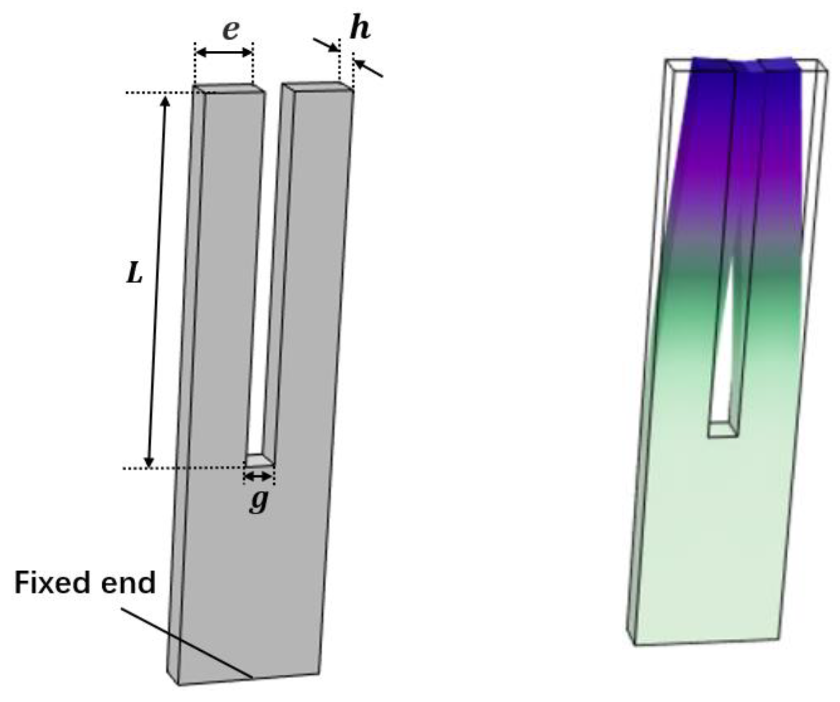
The structure of the tuning fork is shown in the left picture in
Figure 1. The length of the tuning fork arm is
, the width of the tuning fork arm is
, the thickness of the tuning fork arm is
, and the spacing between the tuning fork arms is
. The bottom of the tuning fork is fixed, thus the displacement is zero. The right picture in
Figure 1 is a schematic diagram of the tuning fork performing first-order in-plane anti-phase flexural vibration. This paper mainly studies the relationship between the resonant frequency and quality factor of this vibration mode with respect to fluid density and viscosity. The material of the tuning fork is quartz, with a density of
, and other material property parameters of quartz are defined by the elastic matrix (the conversion matrix between stress and strain, related to material parameters such as Young’s modulus and Poisson’s ratio), the coupling matrix (the conversion matrix between charge and stress) and the relative dielectric constant.
The governing equations for fluid motion in the finite element method are defined by the linear Navier-Stokes equations, including the momentum equation, the continuity equation and the constitutive relation equation:
represents the initial density of the fluid in the absence of disturbance. represents the total acoustic velocity field, represents the initial background acoustic velocity field, and represents the acoustic velocity field generated by tuning fork’s vibration. indicates the total temperature, indicates the initial background temperature, and indicates the temperature change caused by the tuning fork’s vibration. represents the total acoustic pressure, represents the initial background pressure, and represents the acoustic pressure caused by the tuning fork’s vibration. represents the density of the fluid during the propagation of the acoustic wave, represents the coefficient of thermal expansion at constant pressure, represents the dynamic viscosity, and represents the volume viscosity, which is related to the momentum loss caused by the expansion and compression of the fluid. represents the isothermal compression rate, represents the stress, and represents the unit diagonal matrix, .
Fluid in finite element method is compressible fluid, density and dynamic viscosity are related to temperature and pressure. and are set to constants in simulation, so that, and are not affected by temperature and pressure.
When the tuning fork and the fluid are in coupled vibration, their displacements are continuous, satisfying the following relationship:
and represents the displacement of the tuning fork and the velocity of the fluid respectively, and their relationship in the frequency domain is . This coupling relationship shows that the normal stress on the boundary between the tuning fork and the fluid is also continuous.
To sum up, the equations of fluid motion in analytical method and finite element method are both linear Navier-Stokes equations. However, in order to obtain an explicit expression for the resonant frequency and quality factor of the tuning fork with respect to fluid density and viscosity in the process of solving Equation (1), assuming that the viscous effect of the fluid is small, providing only an approximate solution. This approximation does not hold well when the fluid viscosity is large. The finite element method obtain the relationship between tuning fork resonance parameters and fluid characteristic parameters by solving Equation (4) to Equation (8), without approximation. Therefore, the finite element method is more in line with the actual situation than the analytical method, and the simulation results are closer to the actual situation.
2.2.2. Comparison between Finite Element Method and Analytical Method
In the finite element simulation, the material and size of the tuning fork are consistent with those of the laboratory quartz tuning fork in literature [
19]. The length of the tuning fork arm
is 4.05mm, the width
is 0.66mm, the thickness
is 0.4mm, and the spacing
is 0.24mm. The resonant frequency and quality factor of tuning forks in 19 groups of fluids with different densities and viscosities are measured by experiments in reference [
19]. In this paper, finite element method and analytical method are used to simulate the model with parameters identical to those in the experiments. Equations (2) and (3) are used for the analytical method, the value of Young’s modulus
is
, and the value of the material density
of the tuning fork is
. The comparison among numerical simulation results, analytical results and experimental measurement results is shown in
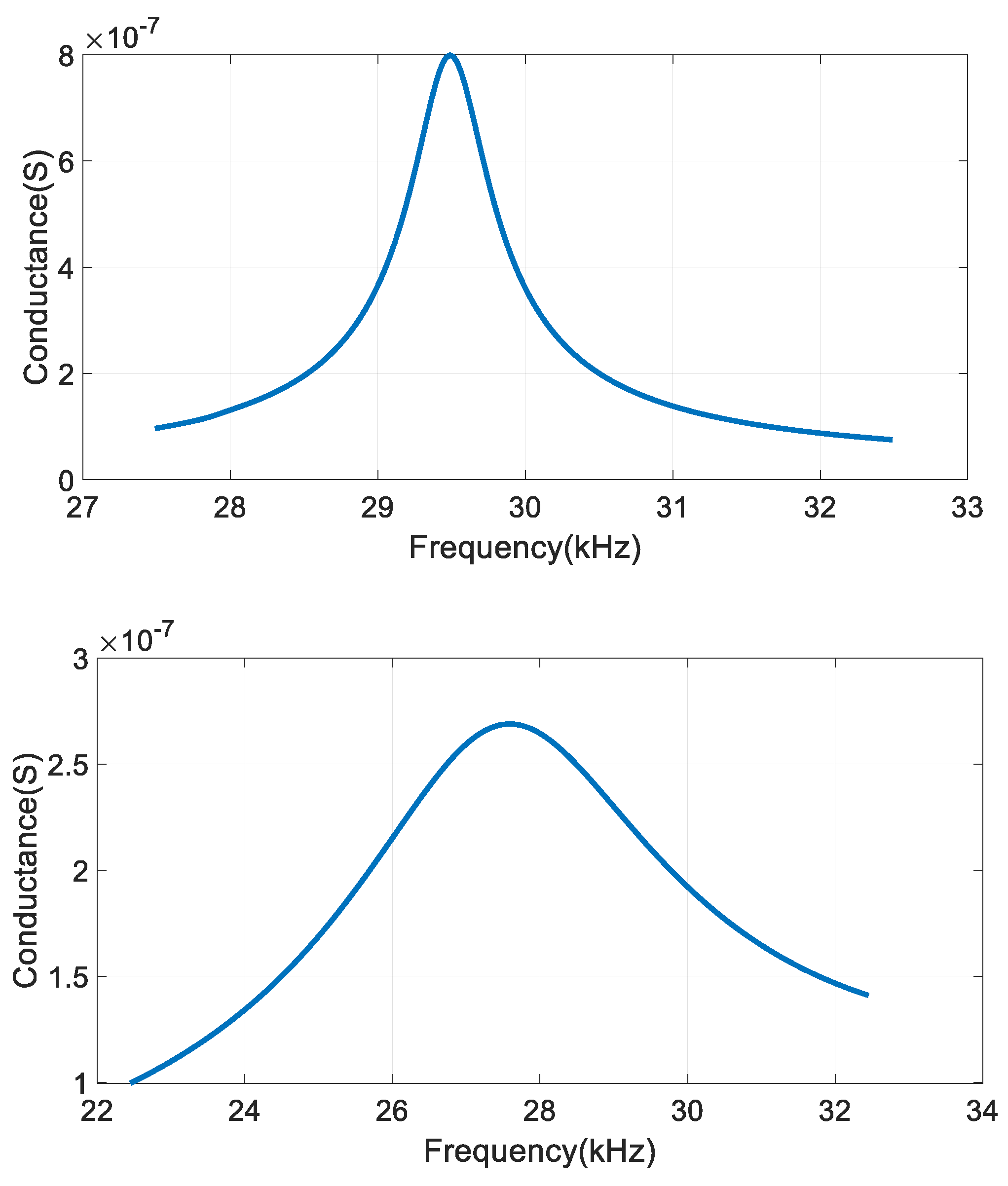
Table 1, where fluids of groups 1-19 are arranged in order of viscosity from small to large. The finite element simulation results are obtained through the conductance diagram, with peak value corresponding to the resonant frequency
of the tuning fork, quality factor
,
is
bandwidth. As shown in
Figure 2, in which the results of group 1 and group 19 are given. The resonant frequency of the tuning fork in fluid of group 1 is
and the quality factor is
. In fluid of group 19, the resonant frequency of the tuning fork is
and the quality factor is
.
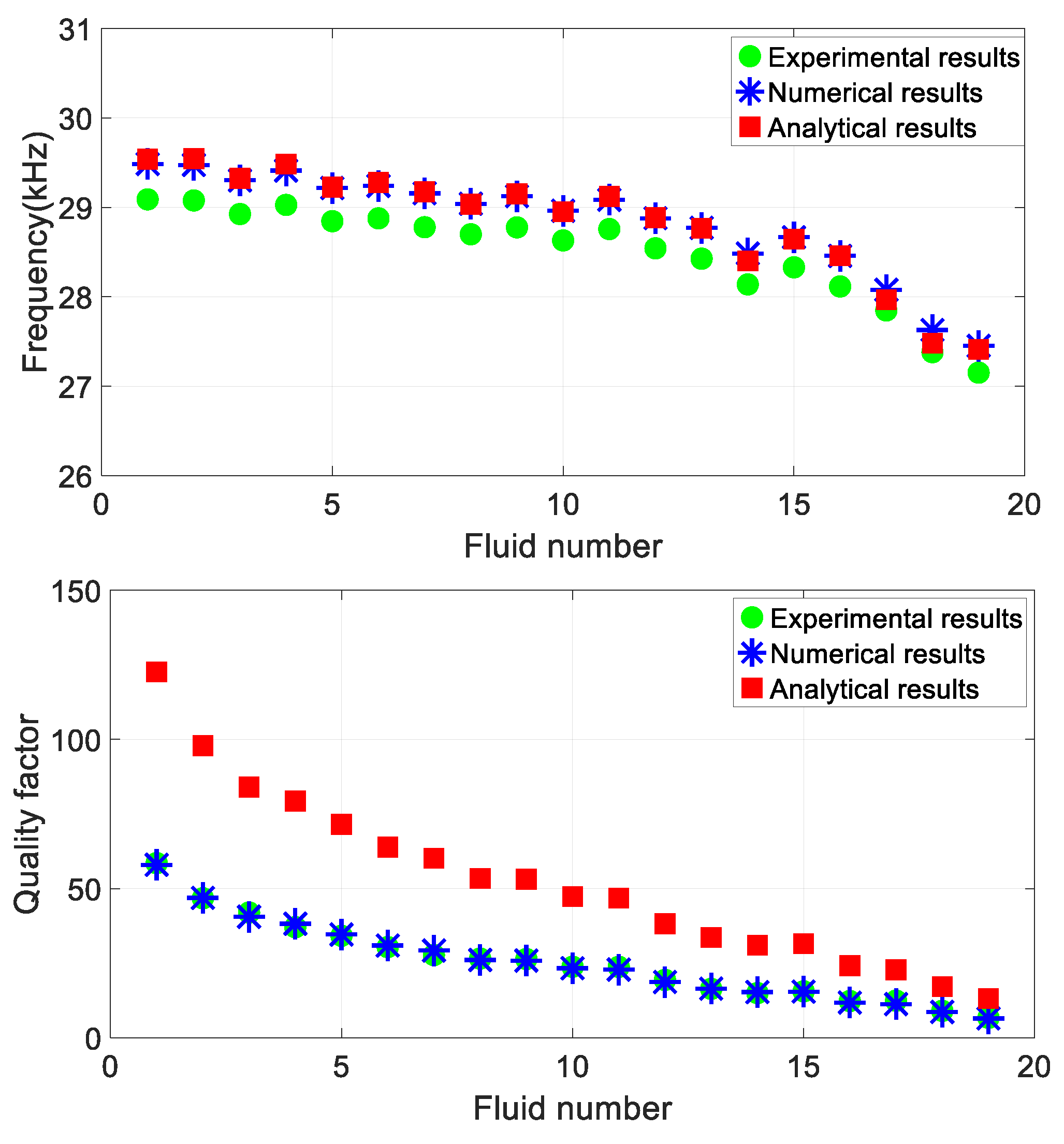
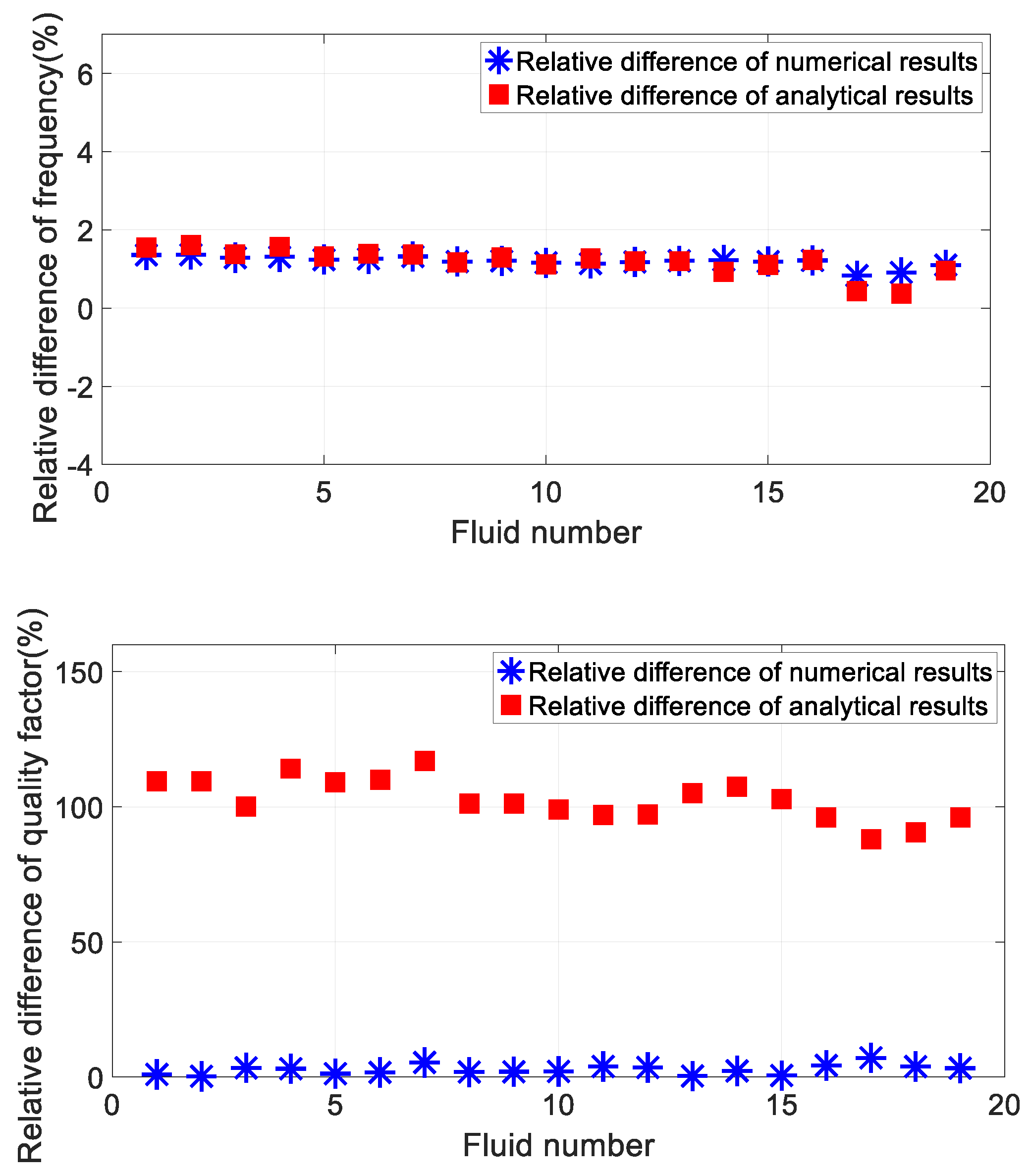
Figure 3 shows the comparison of numerical, analytical and experimental results of resonant frequency and quality factor. Figure. 4 shows the relative differences between numerical results and experimental results, and the relative differences between analytical results and experimental results respectively. Where, the relative difference of numerical results is
, the relative difference of analytical results is
.
From
Figure 3 and
Figure 4, it can be seen that the numerical results and analytical results of the resonant frequency are highly consistent, with a relative difference of less than 2% from the experimental measurement results. The difference between the numerical results and the analytical results of the quality factor is large, the relative difference between the numerical results and the experimental results is less than 4%, and the relative difference between the analytical results and the experimental results can even exceed 110%. This shows that the finite element method includes the influence of fluid viscous effect on tuning fork resonance parameters, which is closer to the actual situation than the approximate analytical method, and the simulation results are more accurate.
3. Results
3.1. Relationship between Tuning Fork Resonance Characteristics and Fluid Characteristic Parameters
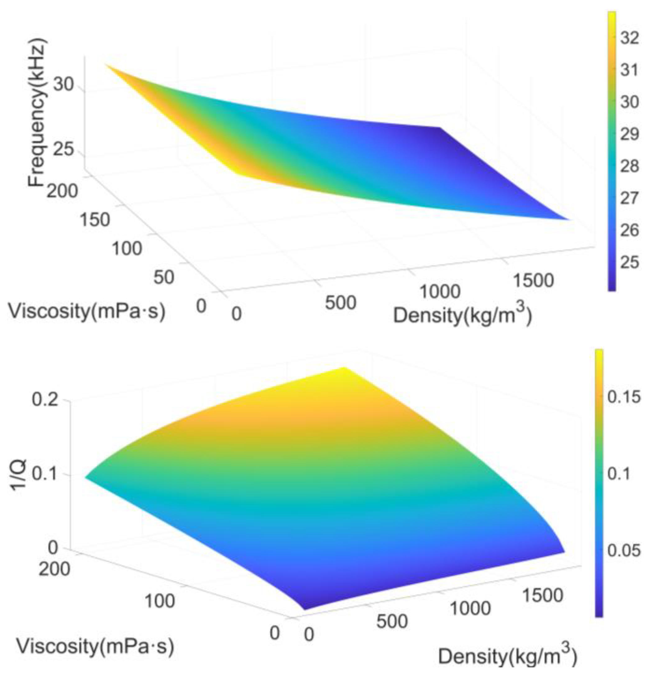
Based on the above conclusions, the finite element method is used in this paper to simulate the relationship between the tuning fork resonance characteristics (resonant frequency and quality factor) and the fluid characteristic parameters (density and viscosity) when the fluid density varies from
to
and the viscosity varies from
to
. The numerical simulation results are shown in
Figure 5.
It can be seen from
Figure 5 that both the resonant frequency and quality factor of the tuning fork decrease with the increase of fluid density and viscosity. The vibration of the tuning fork in the fluid can be regarded as the damped vibration of a oscillator spring system [
20], so the resonant frequency and quality factor can be written as [
14,
21]
represents the elastic coefficient of the spring, represents the mass of the oscillator, represents the spring damping, represents the additional mass of the fluid, and represents the fluid damping. When the tuning fork vibrates in the fluid, the additional mass , where is the effective area of the tuning fork, so the resonant frequency of the tuning fork decreases when the density and viscosity increase, with damping coefficient and . Because as the increasing of and , the increasing trend of is greater than , Therefore, with the increase of and , the quality factor gradually decreases, which can also be understood as and increase, the fluid damping force on the tuning fork increases, leading to greater energy loss in the tuning fork vibration, hence reducing its quality factor.
3.2. Sensitivity Analysis
In finite element numerical simulation, the calculation formula of relative sensitivity is
represents or , represents or , and Formula (11) represents the relative change of resonant frequency or quality factor corresponding to a relative change of unit density or viscosity. The higher the sensitivity, the more sensitive the tuning fork resonance parameters are to the changes of fluid characteristic parameters, resulting in higher measurement accuracy.
The tuning fork size is set to be consistent with that used in the laboratory in the finite element method. Fluid density increases from
to
,
is
, viscosity increases from
to
,
is
,
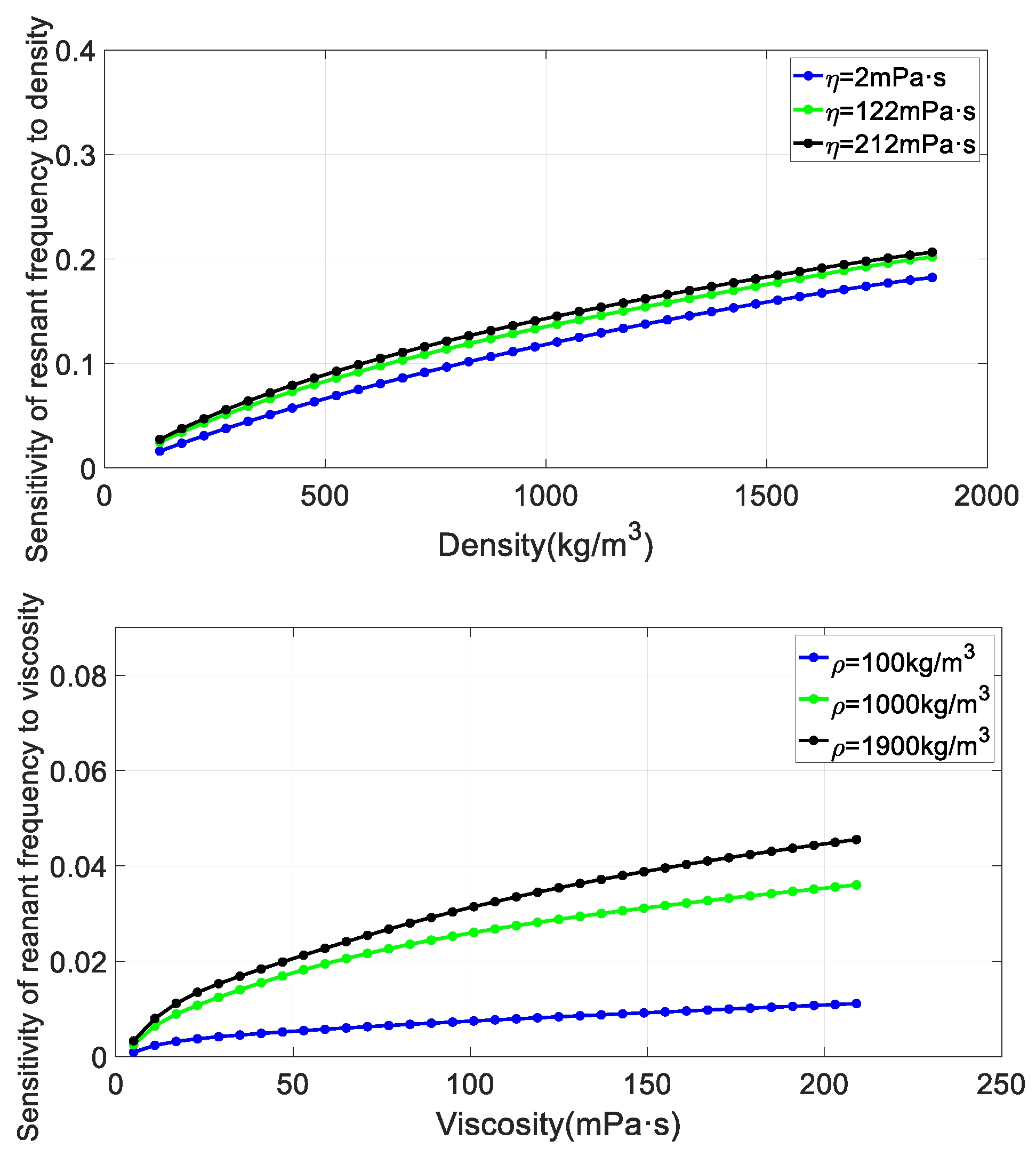
Figure 6 shows the sensitivity of resonant frequency to density and viscosity,
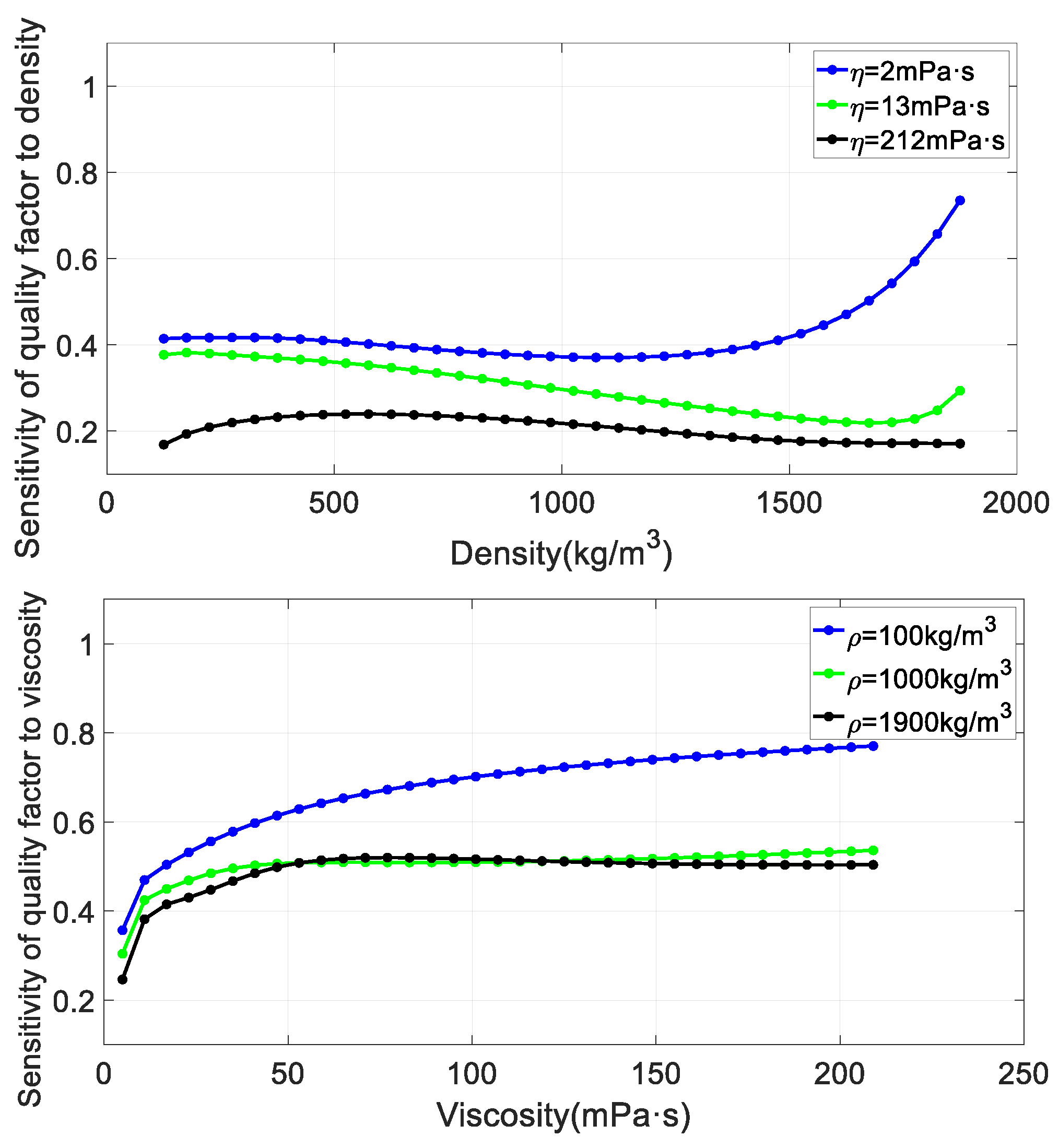
Figure 7 shows the sensitivity of quality factor to density and viscosity.
It can be seen from
Figure 6 that the sensitivity of tuning fork resonant frequency to fluid density and viscosity increases with the increase of fluid density and viscosity, and the sensitivity of tuning fork resonant frequency to fluid density is greater than that to viscosity. It can be seen from the right picture of
Figure 7 that the sensitivity of tuning fork quality factor to fluid viscosity generally increases with the increase of fluid viscosity. The sensitivity value of tuning fork quality factor to fluid density is comparable to that of viscosity. But the sensitivity of quality factor to fluid density does not vary monotonically.
Henisch M. et al. [
15] analyzed the sensitivity of the metal tuning fork driven by electromagnetic means through experiments. However, this approach required setting up experimental platforms and extensive data processing work. Moreover, the analysis results were limited by experimental samples and only the sensitivity of the tuning fork within a small range of density and viscosity variations was analyzed. In contrast, the finite element method does not require the construction of experimental platforms and experiments, and can analyze the sensitivity of the tuning fork when the density and viscosity change in a wide range, which can greatly save time and economic costs.
4. Discussion
Firstly, the existing analytical model of the relationship between tuning fork resonance characteristics and fluid characteristics based on Euler-Bernoulli’s cantilever beam theory is analyzed, which has the limitation being applicable to the small viscous effects of fluid. In this paper, the finite element method is used to simulate the coupling vibration law of the tuning fork and fluid, and the influence of fluid viscous effect on the resonant characteristics of tuning fork is considered. The comparison among the finite element numerical results, analytical results and experimental measurement results shows that the finite element simulation results and experimental measurement results have a higher agreement, and the relative difference rate of resonant frequency between the two is less than 2%, and the relative difference rate of quality factor is less than 4%. It indicates that compared with the approximate analytical method, the finite element method can consider the influence of fluid viscous effect, so it is more in line with the actual situation than the analytical method. Finally, based on the finite element method, the sensitivity of tuning fork resonance characteristics to fluid characteristic parameters (density and viscosity) is calculated. The results show that the sensitivity of tuning fork resonant frequency to fluid density and viscosity increases with the increase of fluid density and viscosity, and the sensitivity of tuning fork quality factor to fluid viscosity generally increases with the increase of fluid viscosity. However, the sensitivity of quality factor to fluid density does not change monotonically. Compared with experiments, this numerical simulation method can be used conveniently to analyze the sensitivity change of tuning fork to fluid density and viscosity when the fluid density and viscosity change in a large range, which can greatly save time and economic cost. It provides a theoretical reference for further optimizing the design of tuning fork sensor to improve the accuracy of measuring fluid characteristic parameters.
Author Contributions
Conceptualization, Feng Jiang, Dehua Chen and Xiao He; methodology, Feng Jiang, Yuyu Dai, Man Tang; software, Feng Jiang; validation, Feng Jiang; formal analysis, Feng Jiang, Dehua Chen, and Xiao He; investigation, Feng Jiang, Mi Zhang.; data curation, Feng Jiang; writing—original draft preparation, Feng Jiang; writing—review and editing, Dehua Chen, Yinqiu Zhou; visualization, Feng Jiang. supervision, Dehua Chen; project administration, Dehua Chen. All authors have read and agreed to the published version of the manuscript.
Funding
This research was funded by the National Natural Science Foundation of China, grant number 42074174, and funded by Chongqing Natural Science Foundation, grant number: CSTB2023NSCQ-MSX0968.
Data Availability Statement
Data can be provided upon request.
Conflicts of Interest
The authors declare no conflict of interest.
References
- Toledo, J.; Ruiz-Díez, V.; Pfusterschmied, G.; Schmid, U.; Sánchez-Rojas, J.L. Flow-through sensor based on piezoelectric MEMS resonator for the in-line monitoring of wine fermentation. Sensors and Actuators, B. Chemical 2018, 54, 291–298. [Google Scholar] [CrossRef]
- Toledo, J.; Jiménez-Márquez, F.; Úbeda, J.; Ruiz-Díez, V.; Pfusterschmied, G.; Schmid, U.; Sánchez-Rojas, J.L. Piezoelectric MEMS resonators for monitoring grape must fermentation. In Proceedings of the Micromechanics Europe 2016: 27th Micromechanics and Microsystems Europe Workshop, Cork, Ireland, 28–30 August 2016. [Google Scholar]
- Sell, J.K.; Niedermayer, A.O.; Babik, S.; Jakoby, B. Gas density sensor for real-time monitoring in a high pressure reactor. Procedia Chemistry 2009, 1, 108–111. [Google Scholar] [CrossRef]
- Voglhuber-Brunnmaier, T.; Niedermayer, A.O.; Feichtinger, F.; Jakoby, B. Fluid sensing using quartz tuning forks—Measurement technology and applications. Sensors 2019, 19, 2336. [Google Scholar] [CrossRef] [PubMed]
- Toledo, J.; Manzaneque, T.; Ruiz-Díez, V.; Jiménez-Márquez, F.; Kucera, M.; Pfusterschmied, G.; Wistrela, E.; Schmid, U.; Sánchez-Rojas, J.L. Comparison of in-plane and out-of-plane piezoelectric microresonators for real- time monitoring of engine oil contamination with diesel. Microsystem Technologies 2016, 22, 1781–1790. [Google Scholar] [CrossRef]
- Xin, Y.; Zeng, J.B.; Cai, D.Y.; Zhang, C.G.; Fan, W.T. The research of tight gas reservoir fluid identification in Kuche. Chinese Journal of Engineering Geophysics 2014, 11, 137–141. [Google Scholar]
- Zhang, H.X.; Zhai, L.S.; Yan, C.; Wang, H.M.; Jin, N.D. Capacitive phase shift detection for measuring water holdup in horizontal oil–water two-phase flow. Sensors 2018, 18, 2234. [Google Scholar] [CrossRef] [PubMed]
- González, M.; Ham, G. Downhole viscosity measurement platform using tuning fork oscillators. In Proceedings of the IEEE SENSORS 2015, Busan, Korea, 13–15 November 2015; pp. 1–4. [Google Scholar]
- González, M.; Seren, H.; Buzi, E.; Deffenbaugh, M. Fast downhole fluid viscosity and density measurements using a self-oscillating tuning fork device. In Proceedings of the 2017 IEEE Sensors Applications Symposium, Glassboro, NJ, USA, 13–15 March 2017. [Google Scholar]
- Rocco, D.; Difoggio, R.; Walkow, A.; Bergren, P.; Reittinger, P.W. Downhole Tool for Drilling or Wire Line Operations, Has Flexural Mechanical Resonator Which is Actuated in Response to Sonde Output to Determine Fluid Parameters. EP Patent 1397661 B1, 10 September 2008.
- Matsiev, L.F.; Bennett, J.; Kolosov, O. High precision tuning fork sensor for liquid property measurements. In Proceedings of the 2005 IEEE Ultrasonics Symposium, Rotterdam, The Netherlands, 18–21 September 2005; pp. 1492–1495. [Google Scholar]
- Sader, J.E. Frequency response of cantilever beams immersed in viscous fluids with applications to the atomic force microscope. Journal of Applied Physics 1998, 84, 64–76. [Google Scholar] [CrossRef]
- Waszczuk, K.; Piasecki, T.; Nitsch, K. , Gotszalk, T. Application of piezoelectric tuning forks in liquid viscosity and density measurements. Sensors and Actuators B: Chemical 2011, 160, 517–523. [Google Scholar] [CrossRef]
- Heinisch, M.; Voglhuber-Brunnmaier, T.; Reichel, E. K. Reduced order models for resonant viscosity and mass density sensors. Sensors and Actuators A: Physical 2014, 220, 76–84. [Google Scholar] [CrossRef]
- Heinisch, M.; Voglhuber-Brunnmaier, T.; Reichel, E. Electromagnetically driven torsional resonators for viscosity and mass density sensing applications. Sensors and Actuators A: Physical 2015, 229, 182–191. [Google Scholar] [CrossRef]
- Zhang, M.; Chen, D.H.; He, X.; Wang, X.M. A Hydrodynamic Model for Measuring Fluid Density and Viscosity by Using Quartz Tuning Forks. Sensors 2020, 20, 198. [Google Scholar] [CrossRef] [PubMed]
- Chon, J.W.M.; Mulvaney, P.; Sader, J.E. Experimental validation of theoretical models for the frequency response of atomic force microscope cantilever beams immersed in fluids. Journal of Applied Physics 2000, 87, 3978–3988. [Google Scholar] [CrossRef]
- Eysden, C.A.V.; Sader, J.E. Frequency response of cantilever beams immersed in viscous fluids with applications to the atomic force microscope: Arbitrary mode order. Journal of Applied Physics 2004, 101, 044908. [Google Scholar] [CrossRef]
- Zhang, M. A study of the method of measuring the density and viscosity of high temperature fluids using a tuning fork. Doctoral thesis, University of Chinese Academy of Sciences, 2021.
- Du, G.H.; Zhu, Z.M.; Gong, X.F. Fundamentals of Acoustics 2rd ed, Nanjing University Press: Nanjing, China, 2012, 9-17.
- Aoust, G.; Levy, R.; Verlhac, B. Optimal quality factor for tuning forks in a fluid medium. Sensors and Actuators A: Physical 2016, 243, 134–138. [Google Scholar] [CrossRef]
|
Disclaimer/Publisher’s Note: The statements, opinions and data contained in all publications are solely those of the individual author(s) and contributor(s) and not of MDPI and/or the editor(s). MDPI and/or the editor(s) disclaim responsibility for any injury to people or property resulting from any ideas, methods, instructions or products referred to in the content. |
© 2024 by the authors. Licensee MDPI, Basel, Switzerland. This article is an open access article distributed under the terms and conditions of the Creative Commons Attribution (CC BY) license (http://creativecommons.org/licenses/by/4.0/).
