Submitted:
19 May 2024
Posted:
23 May 2024
You are already at the latest version
Abstract
Keywords:
1. Introduction
2. Models and Methods
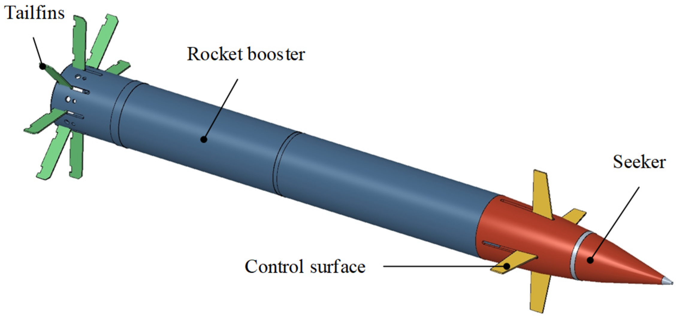
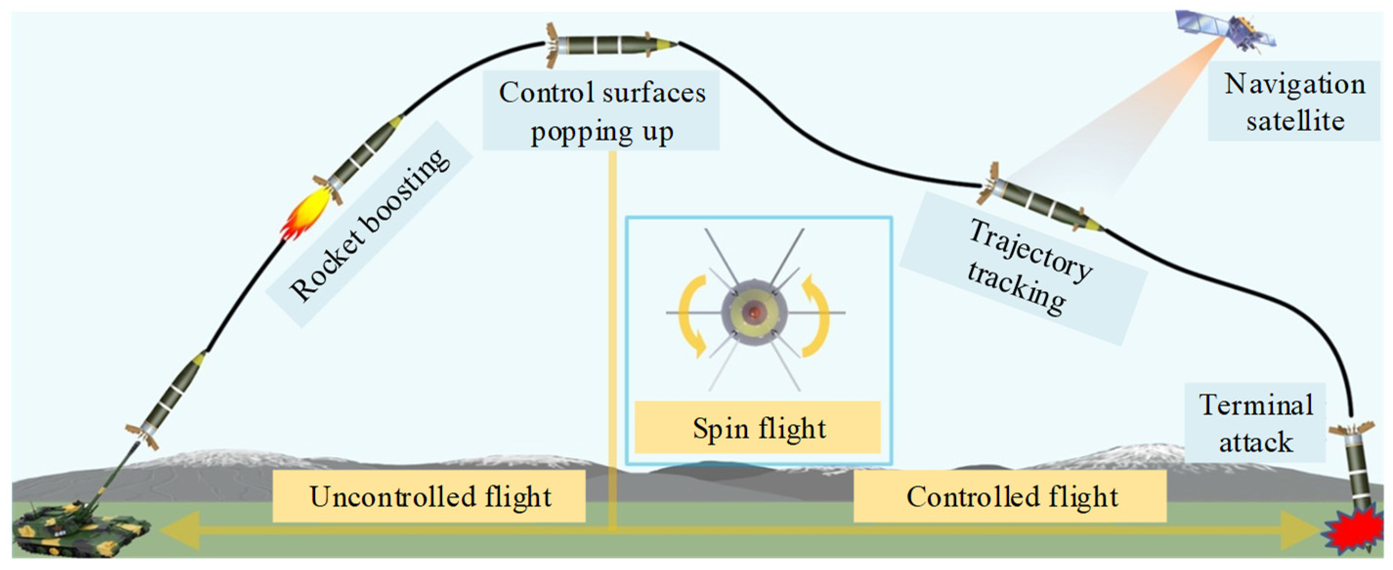
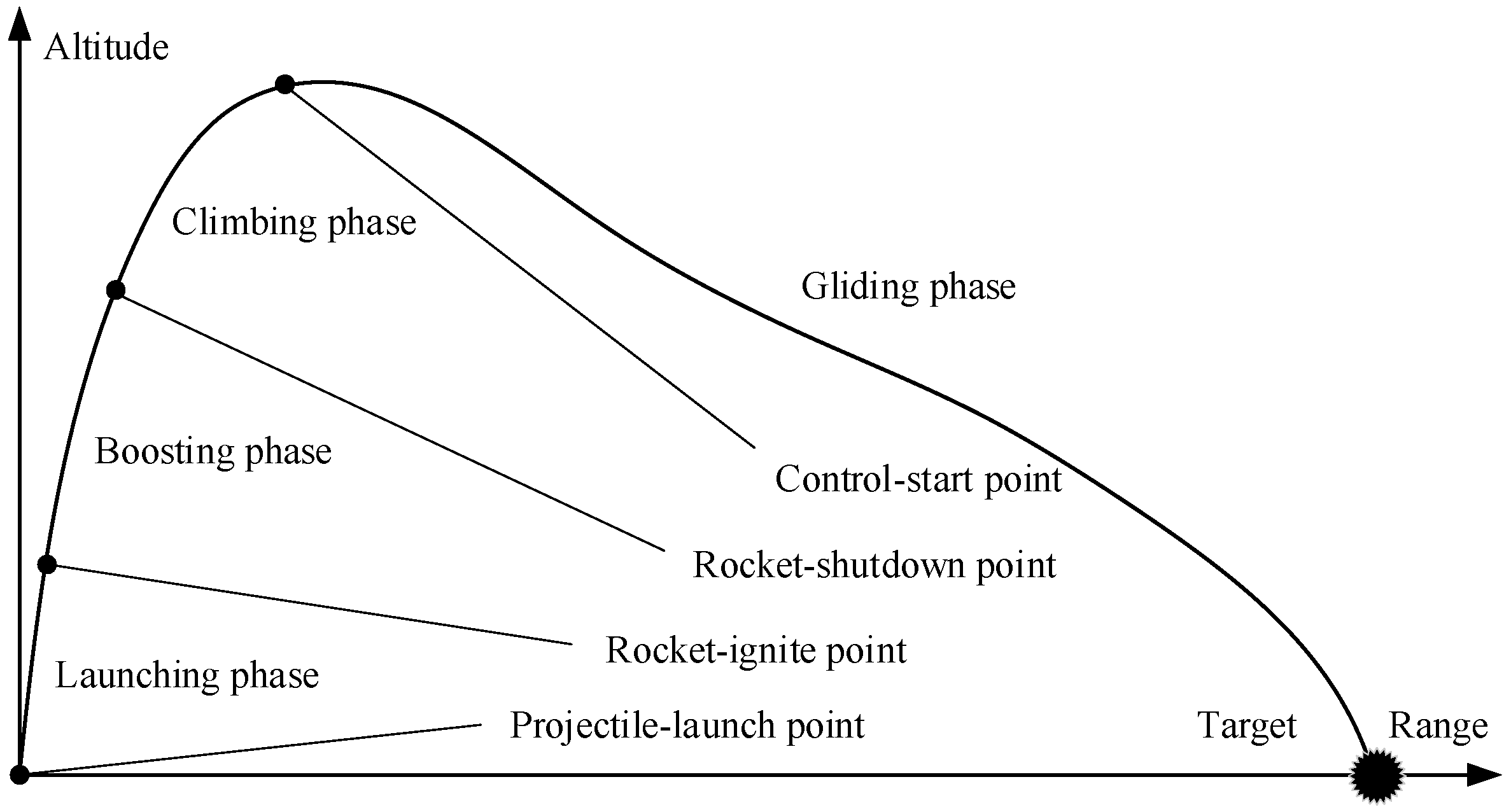
2.1. Structural Composition and Flight Trajectory Principle of Gliding-Guided Projectiles
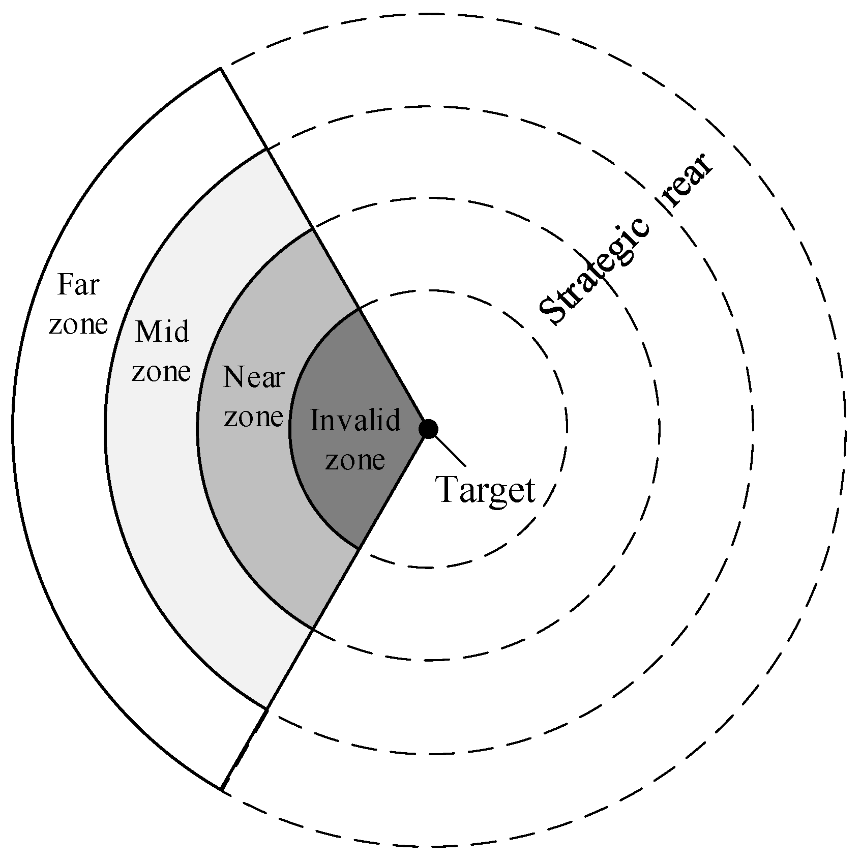
2.2. Division of Battlefield Areas of Gliding Guided Projectiles for Cooperative Attack
- Invalid zone: this zone has a very short range, limited flight time, and minimal adjustability, making cooperative attacks inadvisable.
- Near zone: beyond the invalid zone, this zone lies between the minimum controlled flight range and the maximum unguided flight range. There is no need for range extension in this zone, with flight schemes primarily focusing on increasing terminal velocity to enhance destructive effects.
- Mid zone: beyond the near zone, this zone falls within the maximum controlled flight range with a 50% limit on control surface deflection. There is a certain requirement for range extension in this zone, but with sufficient control margin, flight schemes should balance between enhancing destructive effects and reducing control effort consumption.
- Far zone: beyond the mid zone, this zone falls within the maximum controlled flight range (within a certain distance from the boundary). There is an urgent need for range extension in this zone, shifting the emphasis of flight schemes to minimizing control effort consumption while ensuring the minimum terminal velocity of the projectiles.
2.3. Cooperative Trajectory Planning Model of Gliding-Guided Projectiles
2.3.1. The Artillery-Target Coordinate System
2.3.2. The Cooperation Flight Dynamics Model of Gliding Projectiles
2.3.3. Constraints
- Boundary constraints
- 2.
- Path constraints
- 3.
- Continuity constraints
- 4.
- Cooperation constraint
2.3.4. Performance Indicators
- Near zone: maximize overall terminal velocity.
- Mid zone: taking into account both terminal velocity and control effort consumption.
- Far zone: minimize overall control effort consumption.
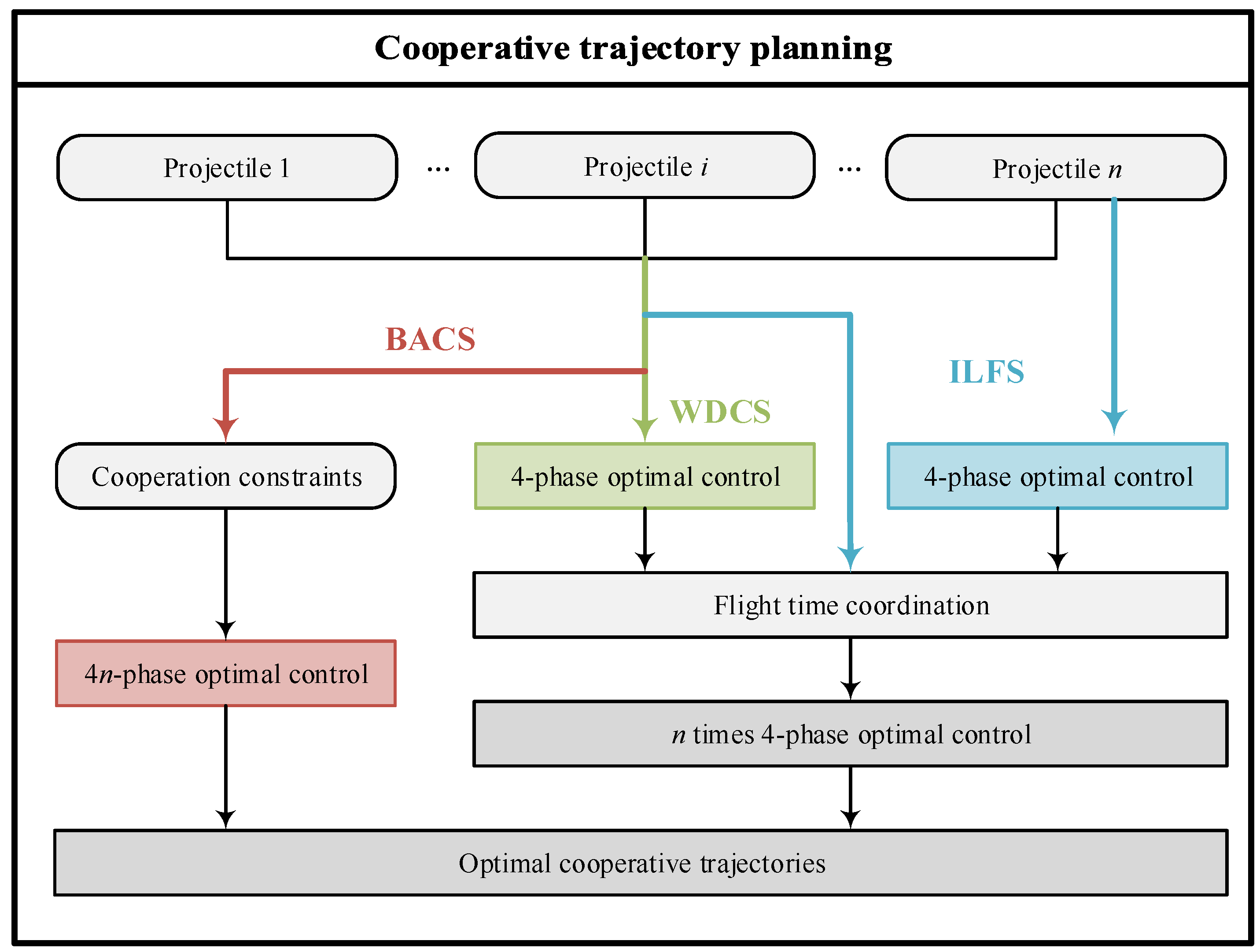
2.3.5. Cooperative Trajectory Planning Flow of Gliding Projectiles
2.4. Flight Time Coordination Strategy of Gliding Guided Projectiles
2.4.1. Improved Leader-Follower Strategy
2.4.2. Weighted Distributed Cooperation Strategy
2.4.3. Bi-Level Adaptive Cooperation Strategy
2.5. Cooperation Capability Range of the Gliding-Guided Projectile
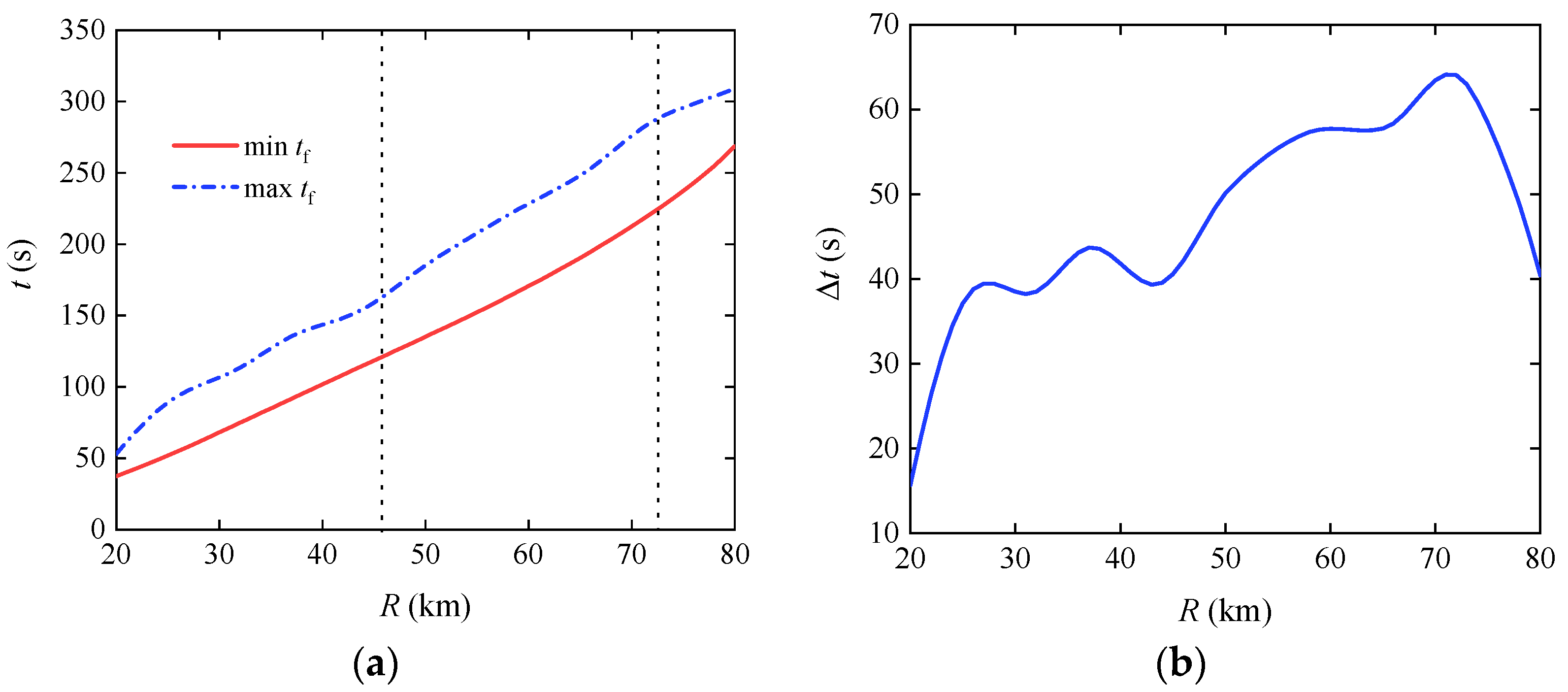
2.5.1. Flight Time Range of the Gliding Projectile at Different Ranges
2.5.2. Cooperation Capability Range of the Gliding Projectile at Different Ranges
- 1.
- The number of cooperation projectiles in single-artillery-multiple-shot scenarios
- 2.
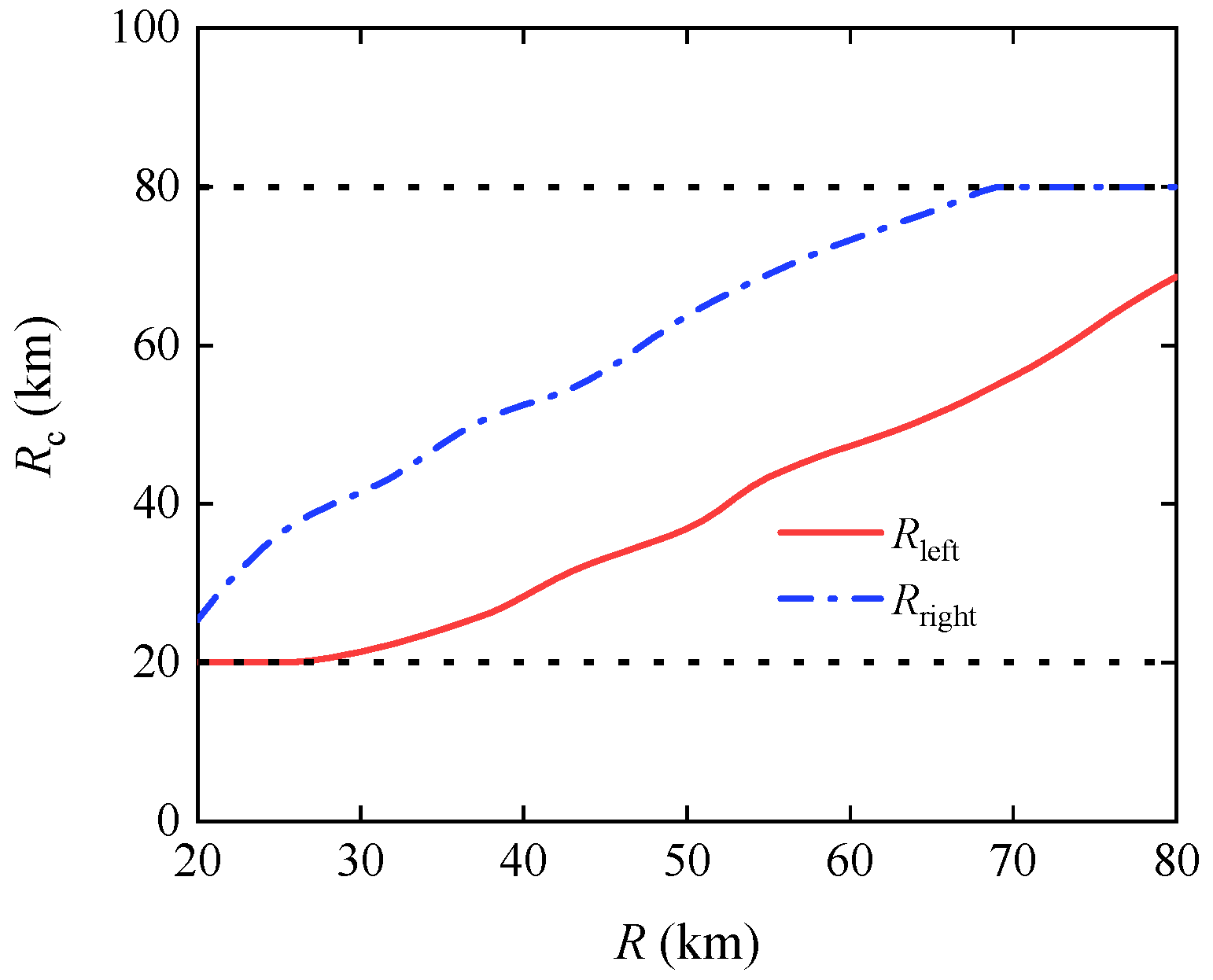
- Feasible cooperative range extents in multi-artillery-simultaneous-launch scenarios
3. Simulation and Analysis
3.1. Division of Battlefield Areas of Gliding Guided Projectiles for Cooperative Attack
3.2. Cooperation Capability Range of the Gliding-Guided Projectile
3.2.1. Flight Time Range of the Gliding Projectile at Different Ranges
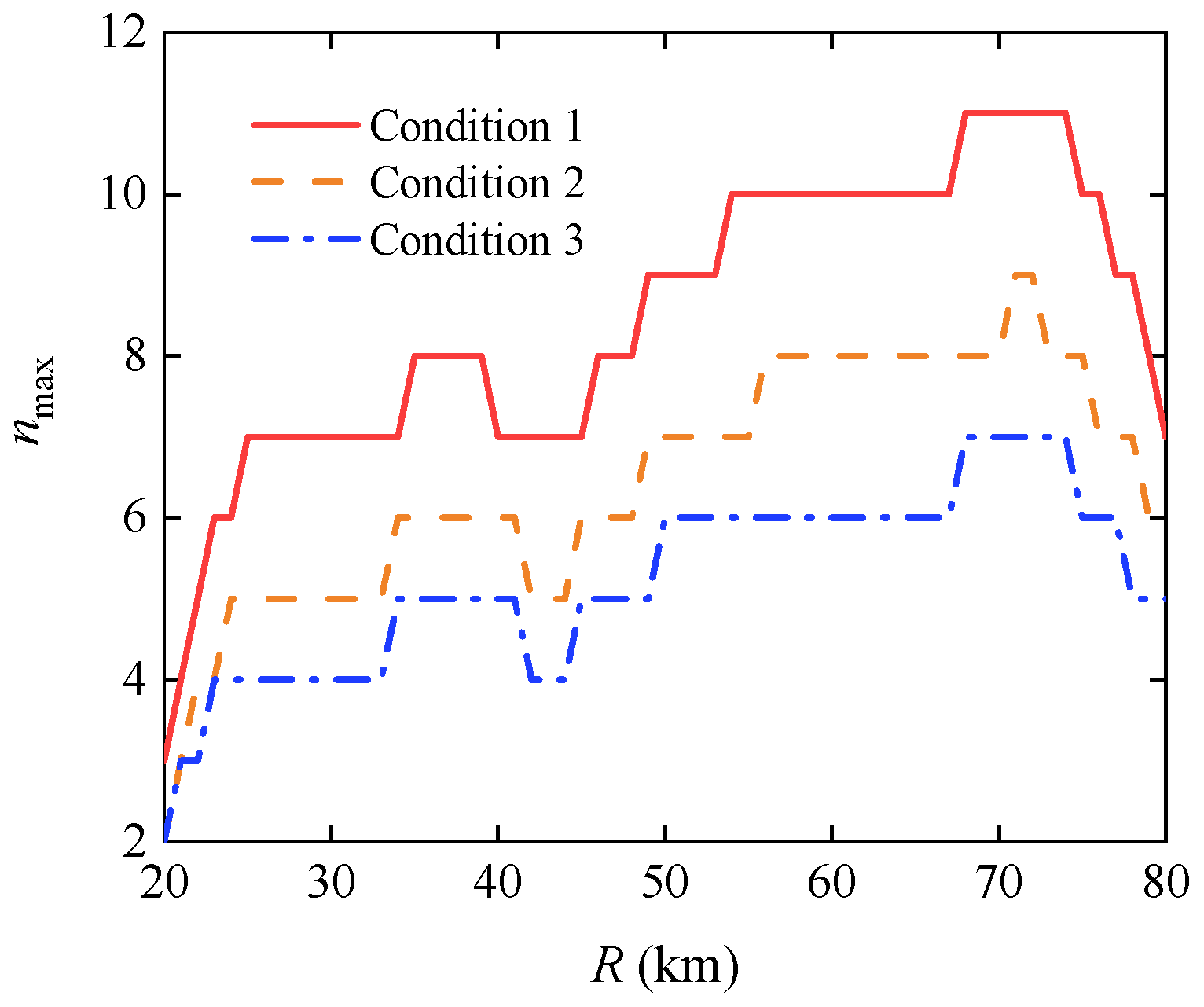
3.2.2. The Number of Cooperation Projectiles in Single-Artillery-Multiple-Shot Scenarios
- Condition 1:
- Condition 2:
- Condition 3:
3.2.3. Feasible Cooperative Range Extents in Multi-Artillery-Simultaneous-Launch Scenarios
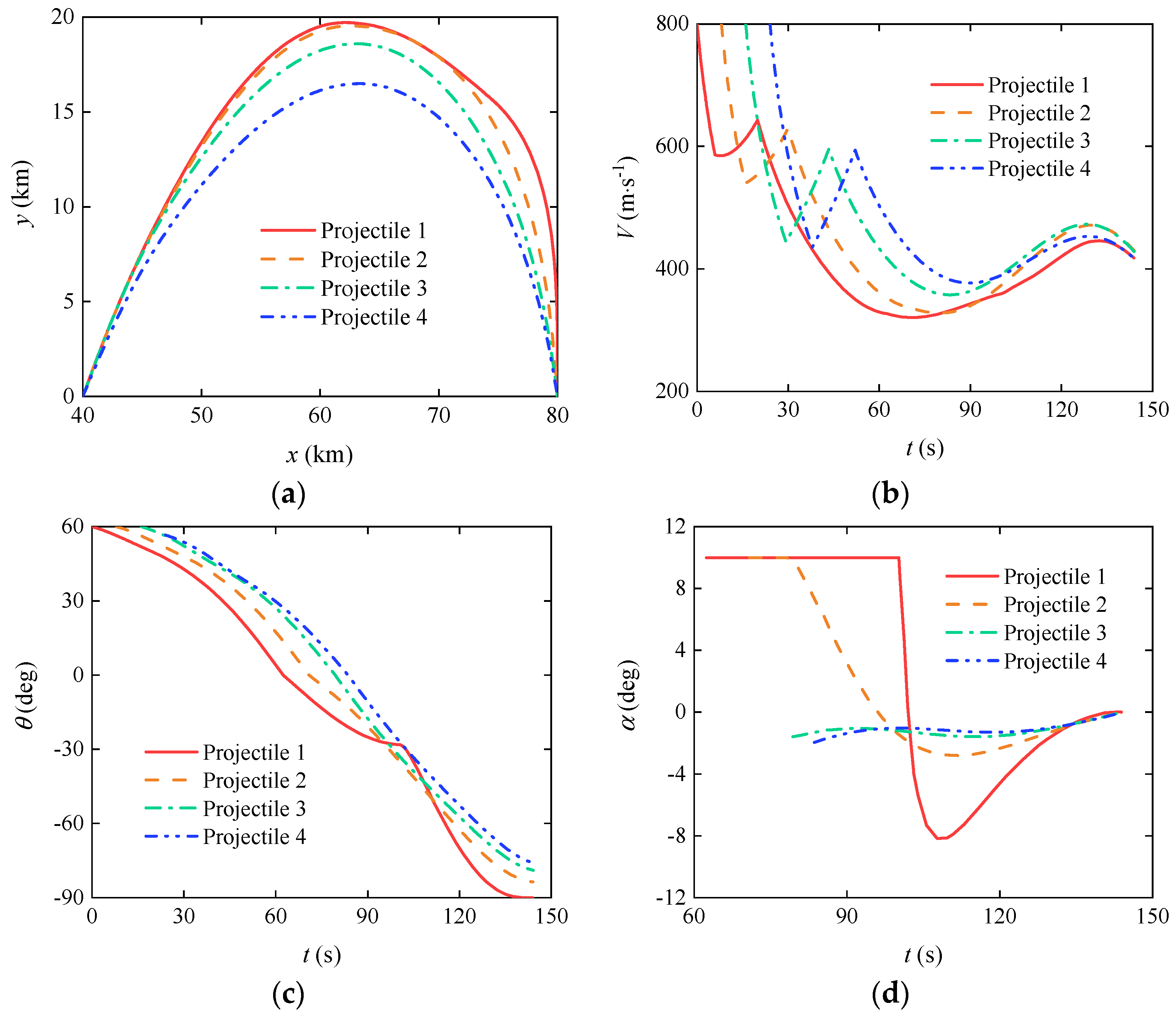
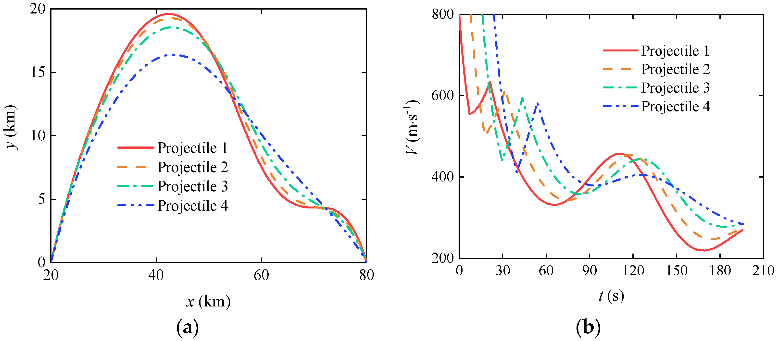
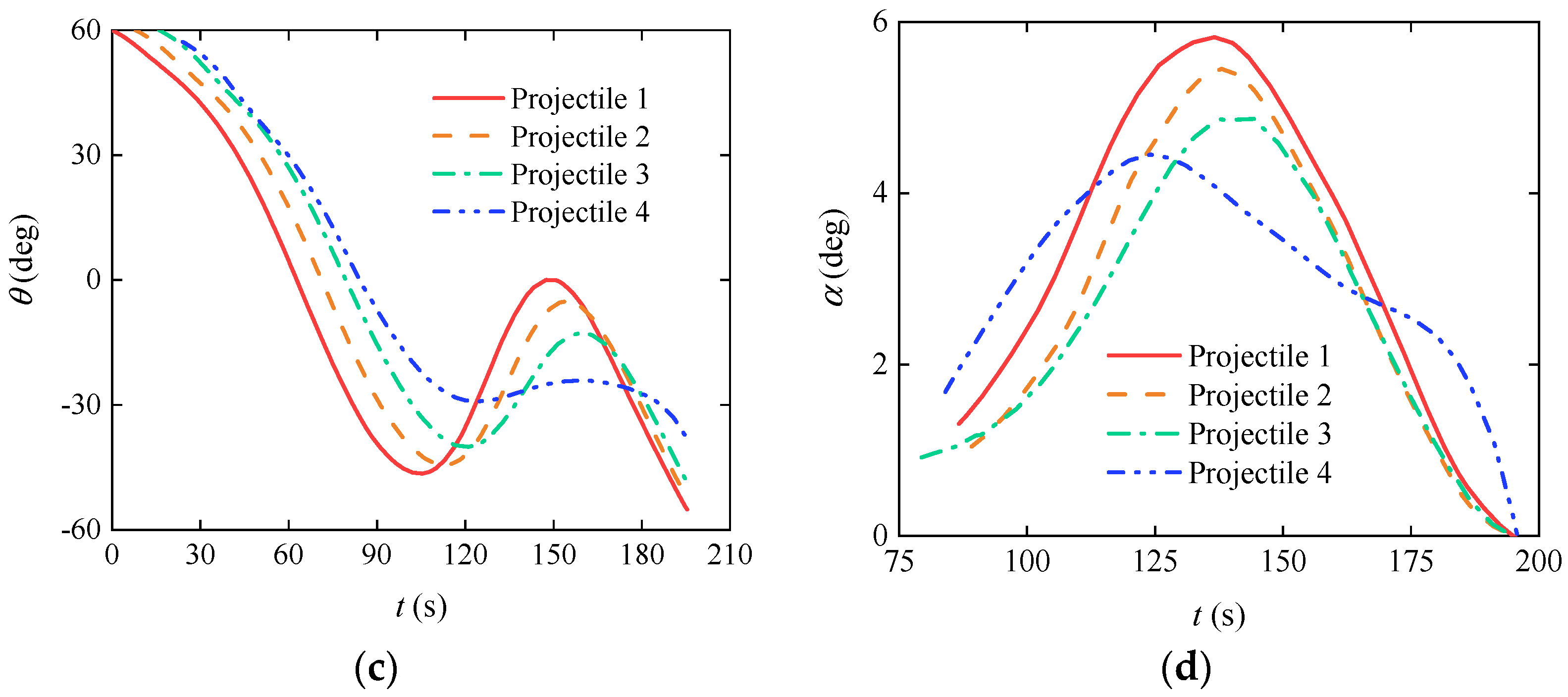
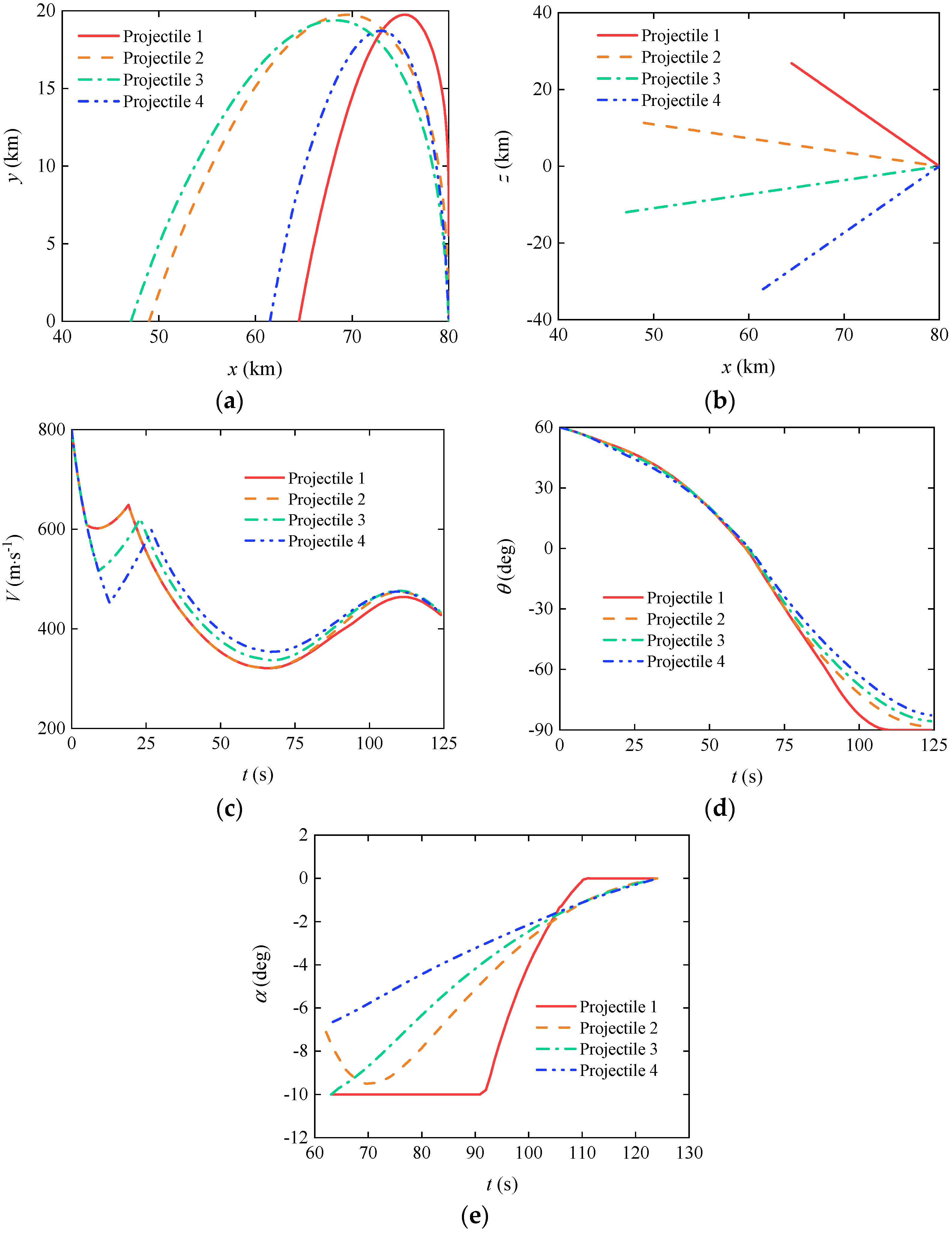
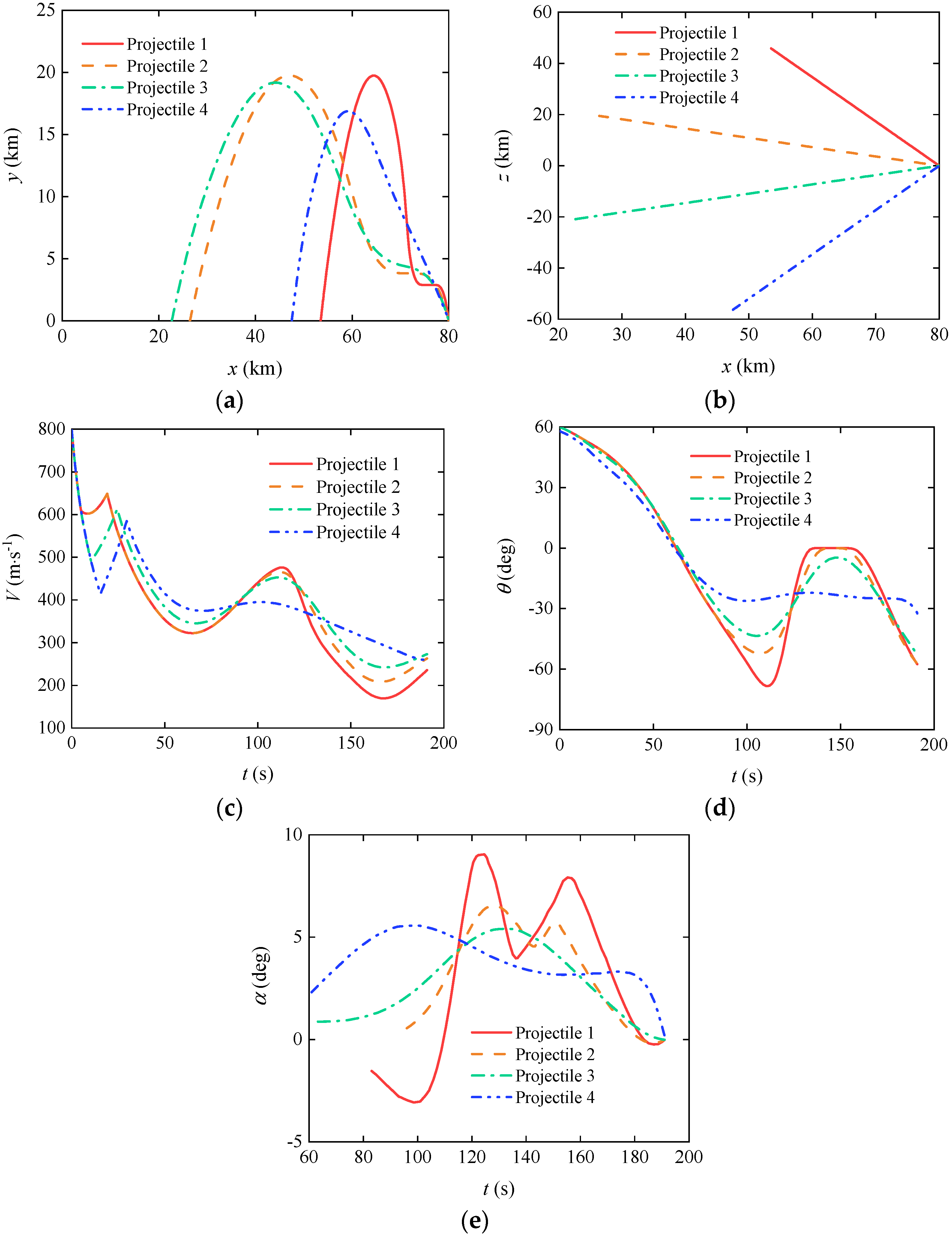
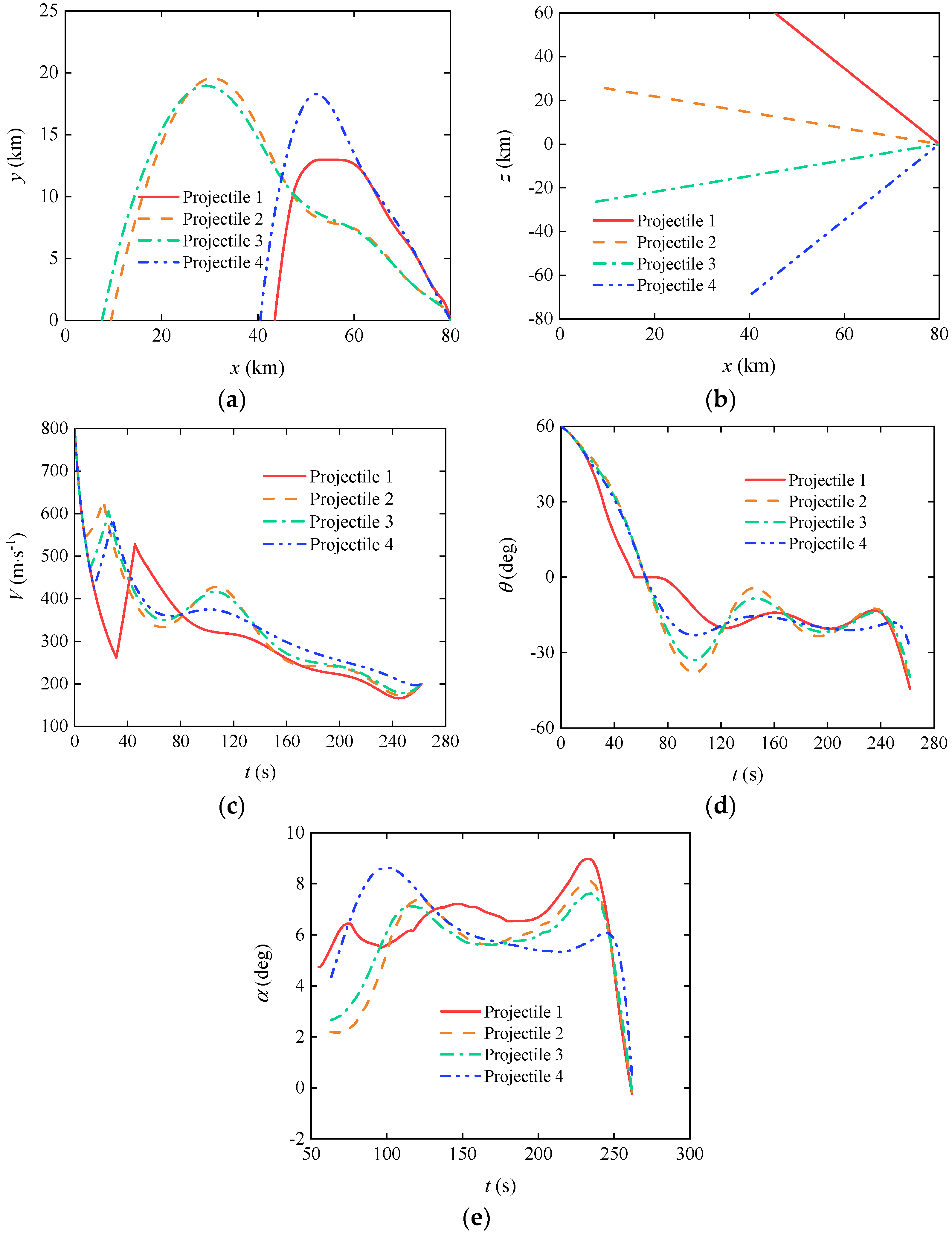
3.3. Cooperative Trajectory Planning of Gliding-Guided Projectiles in Single-Artillery-Multiple-Shot Scenarios
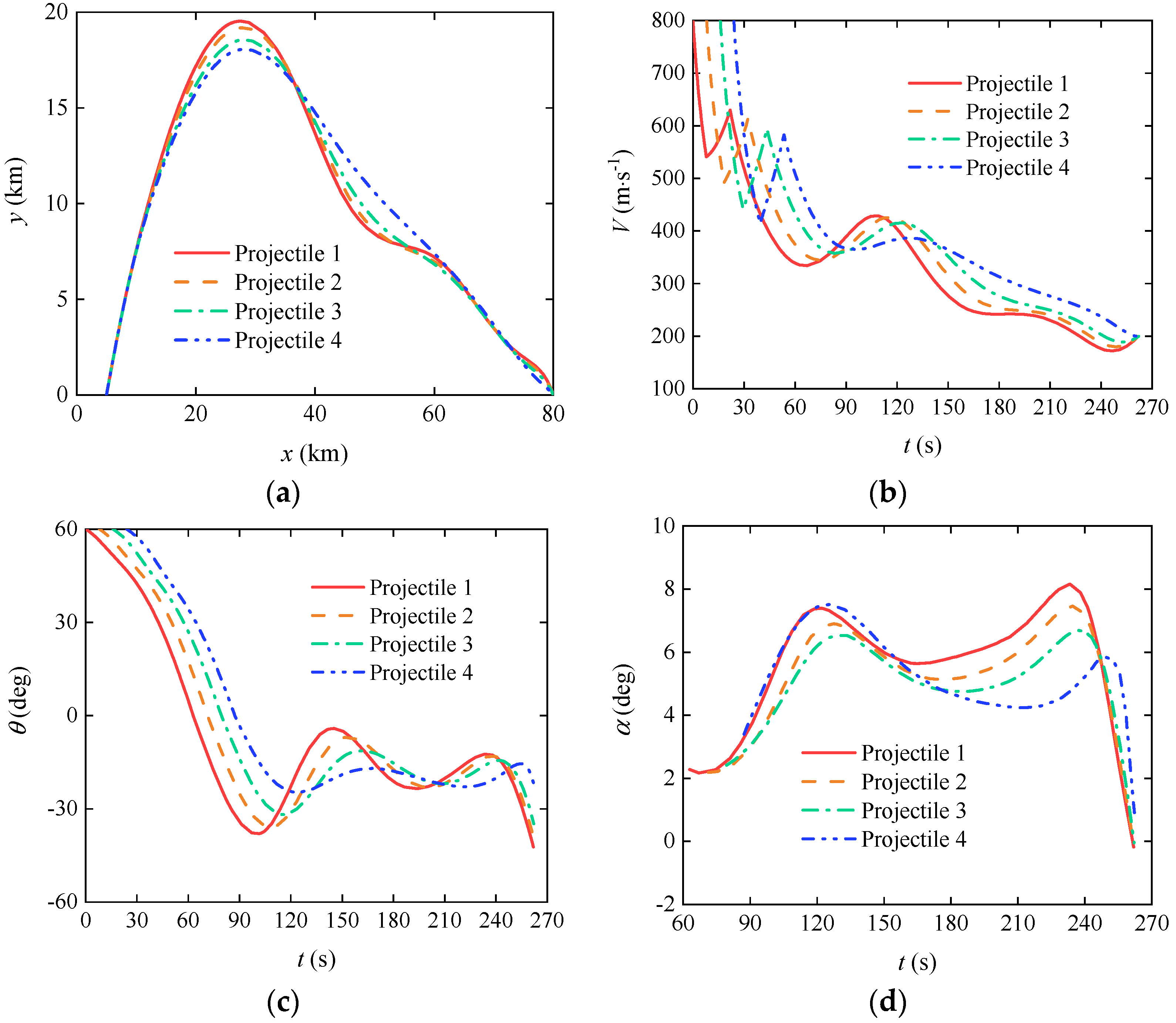
3.4. Cooperative Trajectory Planning of Gliding-Guided Projectiles in Multi-Artillery-Simultaneous-Launch Scenarios
4. Conclusions
- Based on the proposed method for determining the range of projectile cooperative capabilities, feasible working conditions in different cooperation scenarios can be conveniently and effectively obtained, providing references for engineering applications.
- Compared to LFS and DCS in existing literatures, the flight times coordinated by the proposed ILFS and WDCS are within the capability range of most projectiles, offering higher compatibility to the problem. Therefore, ILFS and WDCS can ensure a high success rate even under stringent conditions, but due to the presence of manually designed coordination functions in the algorithms, optimality cannot be guaranteed.
- Under the influence of the proposed BACS, the cooperative flight times of projectiles are adaptively coordinated without manual intervention, ensuring optimality. Moreover, the flight phases of each projectile are independent of each other, enhancing flexibility and aiding in fully exploiting the control potential of the projectile group to achieve maximum efficiency. Consequently, BACS matches well with the study of weakly-maneuverable gliding-guided projectiles and the cooperative trajectory planning issues involving groups of projectiles.
- Increasing the impact angle helps to improve the terminal velocity of the projectiles, but also increases the consumption of control effort. In engineering applications, a trade-off should be made between terminal velocity and control effort consumption, with the pursuit of terminal velocity often coming at a higher cost.
Author Contributions
Funding
Data Availability Statement
Conflicts of Interest
References
- Wang, Z.; Shi, J.; Chang, S.; Wang, X.; Chen, Q. Modern external ballistics; China Science Publishing & Media Ltd.(CSPM): Beijing, China, 2024. [Google Scholar]
- Yi, W.; Wang, Z.; Li, Y.; Zhou, W. Research on ballistic trajectory of glide extended-range projectile with canard configuration in flight. Journal of Projectiles, Rockets, Missiles and Guidance. 2007, 27, 150–153. [Google Scholar]
- Chen, Q. Investigation on trajectory optimization and guidance and control scheme for a type of gliding guided projectiles. PhD, Nanjing University of Science and Technology, Nanjing, China, 2017. [Google Scholar]
- Xu, Q.; Chang, S.; Wang, Z. Composite-efficiency-factor-based trajectory optimization for gliding guided projectiles. J. Spacecr. Rockets. 2018, 55, 66–76. [Google Scholar] [CrossRef]
- Zhao, J.; Yang, S. Review of multi-missile cooperative guidance. Acta Aeronautica et Astronautica Sinica. 2017, 38, 22–34. [Google Scholar]
- Cevher, F.Y.; Leblebicioğlu, M.K. Cooperative guidance law for high-speed and high-maneuverability air targets. Aerospace. 2023, 10, 155. [Google Scholar] [CrossRef]
- Chen, W.; Shao, L.; Lei, H. On-line trajectory generation of midcourse cooperative guidance for multiple interceptors. Journal of Systems Engineering and Electronics. 2022, 33, 197–209. [Google Scholar] [CrossRef]
- Chen, Z.; Zhao, Z.; Xu, J.; Wang, X.; Lu, Y.; Yu, J. A cooperative hunting method for multi-USV based on the A* algorithm in an environment with obstacles. Sensors. 2023, 23, 7058. [Google Scholar] [CrossRef] [PubMed]
- Ma, X.; Dai, K.; Li, M.; Yu, H.; Shang, W.; Ding, L.; Zhang, H.; Wang, X. Optimal-damage-effectiveness cooperative-control strategy for the pursuit–evasion problem with multiple guided missiles. Sensors. 2022, 22, 9342. [Google Scholar] [CrossRef] [PubMed]
- Wang, Z.; Xu, J.; Feng, Y.; Wang, Y.; Xie, G.; Hou, X.; Men, W.; Ren, Y. Fisher-information-matrix-based USBL cooperative location in USV–AUV networks. Sensors. 2023, 23, 7429. [Google Scholar] [CrossRef] [PubMed]
- Song, J.; Zhao, K.; Liu, Y. Survey on mission planning of multiple unmanned aerial vehicles. Aerospace. 2023, 10, 208. [Google Scholar] [CrossRef]
- Huang, T.; Chen, Z.; Gao, W.; Xue, Z.; Liu, Y. A USV-UAV cooperative trajectory planning algorithm with hull dynamic constraints. Sensors. 2023, 23, 1845. [Google Scholar] [CrossRef]
- Liu, N.; Luo, C.; Cao, J.; Hong, Y.; Chen, Z. Trajectory optimization of laser-charged UAVs for charging wireless rechargeable sensor networks. Sensors. 2022, 22, 9215. [Google Scholar] [CrossRef]
- Fevgas, G.; Lagkas, T.; Argyriou, V.; Sarigiannidis, P. Coverage path planning methods focusing on energy efficient and cooperative strategies for unmanned aerial vehicles. Sensors. 2022, 22, 1235. [Google Scholar] [CrossRef] [PubMed]
- Yi, K.; She, S.; Zhang, S.; Hu, B.; Liu, M. Research on cooperative strategy of multiple rockets. In MATEC Web of Conferences, full virtual style(due to COVID-19), 14-16 June 2020, pp. 4009.
- Wei, D.; Qiuqiu, W.; Qunli, X.; Shengjiang, Y. Multiple-constraint cooperative guidance based on two-phase sequential convex programming. Chin. J. Aeronaut. 2020, 33, 296–307. [Google Scholar]
- Chen, Q.; Wang, Z. Optimal trajectory for time-on-target of a guided projectile using direct collocation method. In Proceedings 2013 International Conference on Mechatronic Sciences, Electric Engineering and Computer (MEC), Shenyang, China, 20-22 December 2013; pp. 2803–2806. [Google Scholar]
- Cong, M.; Cheng, X.; Zhao, Z.; Li, Z. Studies on multi-constraints cooperative guidance method based on distributed MPC for multi-missiles. Applied Sciences. 2021, 11, 10857. [Google Scholar] [CrossRef]
- Shen, J.; Wang, X.; Liu, Q.; Yu, J.; Chen, G.; Tian, X. Analysis of time coordinated guidance control for leader-follower smart ammunition formation. In 2020 3rd International Conference on Unmanned Systems (ICUS), Harbin, China, 27-28 November 2020; pp. 214–219. [Google Scholar]
- Xu, Q.; Ge, J.; Yang, T.; Sun, X.; Li, G. Cooperative trajectory planning for penetration of multiple missiles. Journal of Chinese Inertial Technology. 2018, 26, 524–530. [Google Scholar]
- Cui, Z.; Wei, M.; Li, Y. Cooperate trajectory planning method in later part of midcourse based on velocity estimation. Systems Engineering and Electronics. 2023, 45, 1–11. [Google Scholar]
- Chen, Z.; Li, J.; Liu, C.; Li, J.; Liu, X. Task planning method for coordinated attacks on ground targets under time constraints. Systems Engineering and Electronics. 2023, 45, 2353–2360. [Google Scholar]
- Li, Z.; Peng, B.; Chen, H.; Chen, J. Time-coordination reentry trajectory design for reusable launch vehicle. Computer Simulation. 2020, 37, 40–45. [Google Scholar]
- Liu, C.; Zhang, C.; Xiong, F. Multiphase cooperative trajectory planning for multi-missile formation via bi-level sequential convex programming. IEEE Access. 2020, 8, 22834–22853. [Google Scholar] [CrossRef]
- Liu, S.; Li, S.; Liu, Y.; Lv, R.; Ju, M. Research on anti-ship missile cooperative trajectory planning based on Gauss pseudo-spectral method. In Proceedings of 2021 5th Chinese Conference on Swarm Intelligence and Cooperative Control, Shenzhen, China, 19-22 January 2022; pp. 1163–1176. [Google Scholar]
- Yin, Q.; Chen, Q.; Wang, Z.; Wang, Q. Rapid trajectory planning for glide-guided projectiles in single-gun multi-shot scenarios considering time-spatial coordination. Acta Armamentarii. 2024, 45, 798–809. [Google Scholar]
- Liu, C.; Yan, D.; Ge, Y.; Wang, J. Multi-phase cooperative trajectory optimization of dual-pulse aircraft based on decentralized parallel pseudo-spectral algorithm. In 2023 9th International Conference on Control Science and Systems Engineering (ICCSSE), Shenzhen, China, 16-18 June 2023; pp. 214–220. [Google Scholar]
- Yuan, X.; Hu, X.; Qian, H.; Ran, J.; Wei, P.; Li, A. Task allocation and trajectory planning for collaborative adversarial multi-UAV systems. In 2023 IEEE International Conference on Unmanned Systems (ICUS), Hefei, China, 13-15 October 2023; pp. 600–605. [Google Scholar]
- Wang, Z.; Chen, K.; Zheng, H.; Guo, J. Design of a trajectory planning method oriented to generalized simulation. In 3rd International Conference on Autonomous Unmanned Systems(ICAUS), Nanjing, China, 8-11 September 2023; pp. 422–431. [Google Scholar]
- Shi, H.; Lu, F.; Wu, L. Cooperative trajectory optimization of UAVs in approaching phase using feedback guidance methods. Defence Technology. 2023, 24, 361–381. [Google Scholar] [CrossRef]

| Parameter | Value | Parameter | Value | Parameter | Value |
|---|---|---|---|---|---|
| 800 | 7.23 | 35 | |||
| 15 | 1219.2 | 200 | |||
| 60 | 14.068 | 10 | |||
| 44.5 | 0.0133 |
| Battlefield Area | Lower Bound (km) | Upper Bound (km) |
|---|---|---|
| Near zone (including Invalid zone) |
15.93 | 43.27 |
| Mid zone | 43.27 | 72.49 |
| Far zone | 72.49 | 83.72 |
| Node | Range (km) | Lower Bound (s) | Upper Bound (s) |
| 1 | 20 | 37.34 | 53.12 |
| 2 | 25.82 | 54.41 | 93.06 |
| 3 | 31.64 | 73.67 | 112.21 |
| 4 | 37.45 | 93.25 | 136.95 |
| 5 | 43.27 | 112.68 | 152.06 |
| 6 | 50.58 | 137.09 | 187.84 |
| 7 | 57.88 | 162.71 | 220.13 |
| 8 | 65.19 | 191.18 | 249.15 |
| 9 | 72.49 | 224.31 | 287.89 |
| 10 | 74.37 | 233.93 | 293.91 |
| 11 | 76.25 | 244.25 | 299.06 |
| 12 | 78.12 | 255.58 | 303.87 |
| 13 | 80 | 268.57 | 309.22 |
| Battlefield Area | Cooperative Flight Time (s) | Performance Indicator Value | ||||
| LFS | ILFS | BACS | LFS | ILFS | BACS | |
| Near zone | 146.23 | 125.83 | 143.97 | × | -1517.70 | -1690.80 |
| Mid zone | 198.35 | 193.60 | 195.50 | -1.2568 | -1.1635 | -1.4442 |
| Far zone | 261.68 | 261.29 | 261.97 | 7.6308 | 7.6307 | 7.6309 |
| Battlefield Area | Cooperative Flight Time (s) | Performance Indicator Value | ||||
| DCS | WDCS | BACS | DCS | WDCS | BACS | |
| Near zone | 109.76 | 116.00 | 123.98 | -1652.48 | -1691.36 | -1725.38 |
| Mid zone | 173.49 | 195.01 | 191.00 | × | 2.16 | 0.33 |
| Far zone | 247.90 | 274.00 | 261.88 | × | 12.69 | 9.48 |
Disclaimer/Publisher’s Note: The statements, opinions and data contained in all publications are solely those of the individual author(s) and contributor(s) and not of MDPI and/or the editor(s). MDPI and/or the editor(s) disclaim responsibility for any injury to people or property resulting from any ideas, methods, instructions or products referred to in the content. |
© 2024 by the authors. Licensee MDPI, Basel, Switzerland. This article is an open access article distributed under the terms and conditions of the Creative Commons Attribution (CC BY) license (http://creativecommons.org/licenses/by/4.0/).


