Submitted:
23 May 2024
Posted:
24 May 2024
You are already at the latest version
Abstract
Keywords:
1. Introduction
2. Materials and Methods
- forget steel;
- ceramics with fibres;
- cementitious composites.
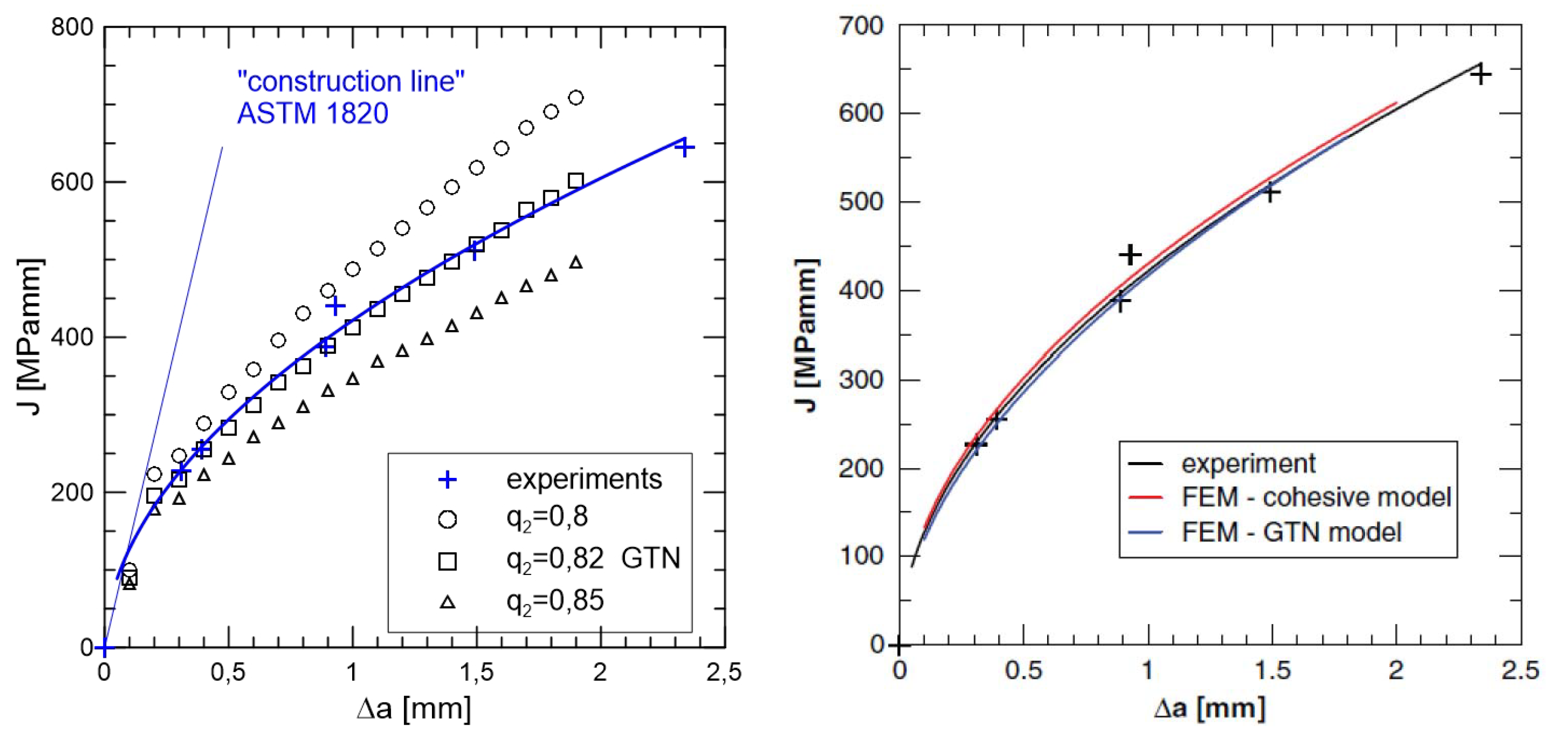
2.1. Forget Steel
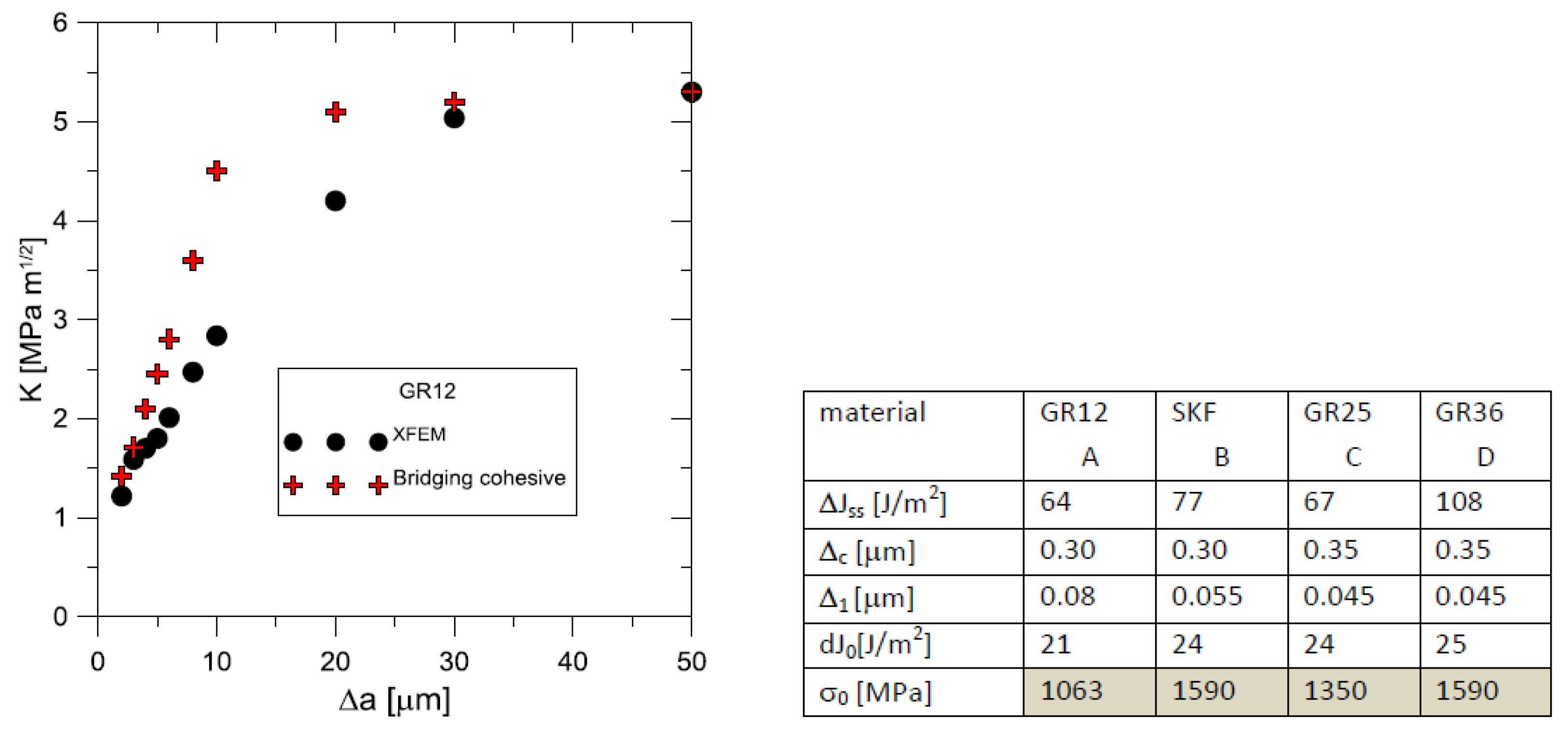
2.2. Ceramics with Fibres
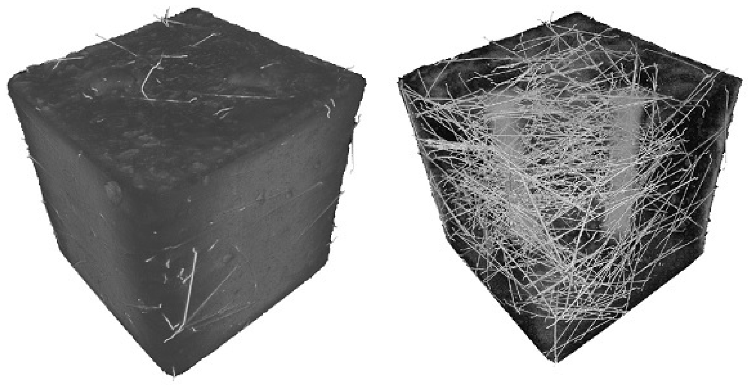
2.3. Cementitious Composites
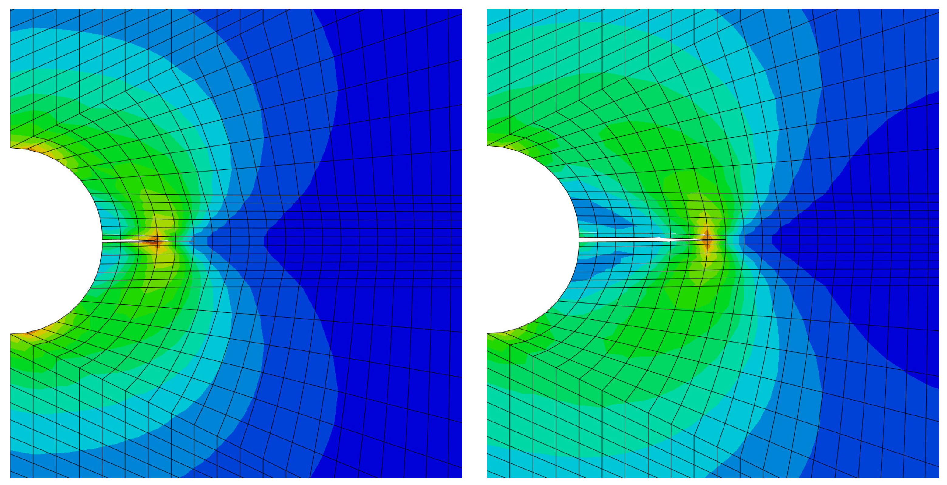
2.4. Numerical Adjustment
2.5. Computational Algorithms and their Convergence Properties
3. Results and Discussion
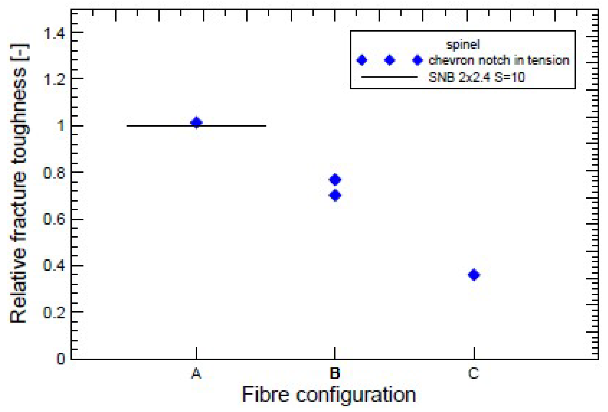
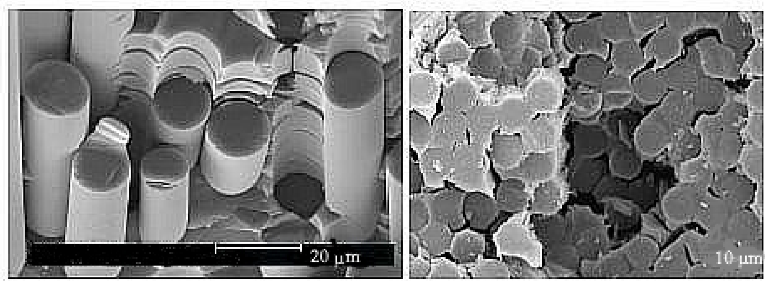
- Fibre bridging in crack growth realizes an increase in fracture toughness associated with an increased level of strength in ceramics, similar to the interaction of grains in ductile materials.
- When modelling behaviour commercial ceramic as is SiN, see Figure 12, the onset and initiation of the crack length is slower when we introduce the effect of bridging into the model.
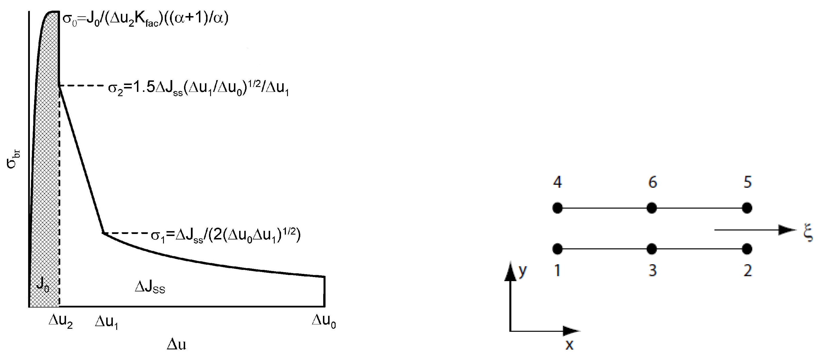
- It is very likely that early real bridging starts due to numerical oscillation and the obtained values of displacements after the crack initiation are smaller, see the shape of the traction separation law in Figure 6.
- Real determination of the shape of the separation curve generates J – R prediction, at least maximum stress must be determined on the base of careful experimental procedures.
4. Conclusions
- The procedure for implementing the cohesion element into the FEM system was indicated.
- With the advent of fibre composites in technical practice, it is essential to be able to predict or model the behaviour of these materials. Numerical methods solve not only new or modified procedures, including the existence of solutions, but the modelling result must clearly approach reality. The problem is that many of the input data are estimated, which increases the risk of a possible wrong prediction.
- An example of introduced numerical problems is the form of the traction separation law in cohesion models.
- Talking about the fineness of the FEM network can be counterproductive, it is necessary to start from the size of the RVE (representative volume element).
- Small modifications of XFEM with a focus on the applicability of these procedures were also tested on practical examples.
- For the modeling of microstructural behaviour using XFEM, it is often necessary to use, or rather to introduce, a real traction separation law.
- Careful determination of the traction separation law representing all phases of fibre reinforced composite behaviour enables a more accurate prediction of crack propagation predominantly in the initial phase of failure.
- In the case of cement composites, it is reasonable to use models that in a certain way average the stress field in front of the crack front.
- The combination of traction separation law and XFEM is a promising approach for crack propagation modelling, as a strong motivation for further research.
Author Contributions
Data Availability Statement
Acknowledgments
Conflicts of Interest
References
- Yu, W. A review of modeling of composite structures. Materials 2024, 17, 446 / 1–23.
- Slatcher, S.; Evandt, Ø. Practical application of the weakest link model to fracture toughness problems. Eng. Fract. Mech. 1986, 24, 495–508.
- Cui, W. A state-of-the-art review on fatigue life prediction methods for metal structures. J. Mar. Sci. Technol. 2002, 7, 43–56.
- Krejsa, M.; Seitl, S.; Brožovslý, J.; Lehner, P. Fatigue damage prediction of short edge crack under various load: direct optimized probabilistic calculation. Procedia Struct. Integrity 2017, 5, 1283–1290.
- Hun, D.-A.; Guilleminot, J.; Yvonnet, J., Bornert, M. Stochastic multiscale modeling of crack propagation in random heterogeneous media. Int. J. Numer. Methods Eng. 2019, 119, 1325–1344.
- Kotrechko, S.; Kozák, V.; Zatsarna, O.; Zimina, G.; Stetsenko, N.; Dlouhý, I. Incorporation of temperature and plastic strain effects into local approach to fracture. Materials 2021, 14, 6224 / 1–11.
- Mieczkowski, G.; Szymczak, T.; Szpica, D.; Borawski, A. Probabilistic modelling of fracture toughness of composites with discontinuous reinforcement. Materials 2023, 16, 2962 / 1–15.
- Le, B. D.; Koval, G.; Chazallon, C. Discrete element approach in brittle fracture mechanics. Eng. Comput. 2013, 30, 263–276.
- Guan, J.; Zhang, L.; Li, L.; Yao, X.; He, S.; Niu, L.; Cao, H. Three-dimensional discrete element model of crack evolution on the crack tip with consideration of random aggregate shape. Theor. Appl. Fract. Mech. 2023, 127, 104022 / 1–16.
- Xu, G.; Yue, Q.; Liu, X. Deep learning algorithm for real-time automatic crack detection, segmentation, qualification. Eng. Appl. Artif. Intell. 2023, 126, 1070852 / 1–22.
- Griffith, A. A. The phenomena of rupture and flow in solids. Philos. Trans. R. Soc. A 1920, 221, 163–198.
- Sih, G. C. Strain-energy density factor applied to mixed mode crack problems. Int. J. Fract. 1974, 10, 304–321.
- Sun, C. T.; Jin, Z. H. A comparison of cohesive zone modelling and classical fracture mechanics based on near tip stress field. Int. J. Solids Struct. 2006, 43, 1047–1060.
- Rice, J. R. A path independent integral and the approximate analysis of strain concentration by notches and cracks. J. Appl. Mech. 1968, 35, 379–386.
- Goutianos, S. Derivation of path independent coupled mix mode cohesive laws from fracture resistance curves. Appl. Comp. Mater. 2017, 24, 983–997.
- Barenblatt, G. I. The mathematical theory of equilibrium of cracks in brittle fracture. Adv. Appl. Mech. 1962, 7, 55–129.
- Erdogan, F.; Sih, G. C. On the crack extension in plates under plane loading and transverse shear. J. Basic Eng. 1963, 85, 519–527.
- Enescu, I. Some researches regarding stress intensity factors in crack closure problems. WSEAS Trans. Appl. Theor. Mech. 2018, 13, 187–192.
- Tabiei, A.; Zhang, W. Cohesive element approach for dynamic crack propagation: Artificial compliance and mesh dependency. Eng. Fract. Mech. 2017, 180, 23–42.
- Papenfuß, Ch. Continuum Thermodynamics and Constitutive Theory; Springer: Berlin, 2020.
- Hashiguchi, K. Elastoplasticity Theory; Springer: Berlin, 2014.
- Morandotti, M. Structured deformation of continua: theory and applications. In: Mathematical Analysis of Continuum Mechanics and Industrial Applications II – Proc. CoMFoS16 (Continuum Mechanics Focusing on Singularities) in Kyushu (2016); Springer: Singapore, 2018, 125–136.
- Del Piero G.; Owen D. R. Structured deformations of continua. Arch. Ration. Mech. Anal. 1993, 124, 99–155.
- Ogawa, K.; Ichitsubo, T.; Ishioka, S.; Ahuja, R. Irreversible thermodynamics of ideal plastic deformation. Cogent Phys. 2018, 5, 1496613 / 1–7.
- Taira, S.; Ohtani, R.; Kitamura, T. Application of J-integral to high-temperature crack propagation, Part I – Creep crack propagation. J. Eng. Mater. Technol. 1979, 101, 154–161.
- Landes, J. D.; Begley, J. A. Mechanics of Crack Growth; ASTM International: West Conshohocken (Pennsylvania, US), 1976.
- Riedel, H. Fracture at High Temperatures; Springer: Berlin, 1987.
- Kolednik, O.; Schöngrundner, F.; Fischer, D. A new view on J-integrals in elastic–plastic materials. Int. J. Fract. 2014, 187, 77–107.
- Scheel, J.; Schlosser, A.; Ricoeur, A. The J-integral for mixed-mode loaded cracks with cohesive zones. Int. J. Fract. 2021, 227, 79–94.
- Healy B.; Gullerund, A.; Koppenhoefer, K.; et al. WARP3D Release 18.3.6. User Manual, 3-D Dynamic Nonlinear Fracture Analysis of Solids; University of Illinois: Chicago, 2023.
- Betegón, C.; Hancock, J. W. Two-parameters characterization of elastic-plastic crack tip field. J. Appl. Mech. 1991, 58, 104–110.
- Gupta, M.; Anderliesten, R. C.; Benedictus, R. A review of T-stress and its effects in fracture mechanics. Eng. Fract. Mech. 2015, 134, 218–241.
- Cedolin, L.; Bažant, Z. P. Effect of finite element choice in blunt crack band analysis. Comput. Methods Appl. Mech. Eng. 1980, 24, 205–316.
- Beissel, S. R.; Johnson, G. R.; Popelar, C. H. An element-failure algorithm for dynamic crack propagation in general direction. Eng. Fract. Mech. 1998, 61, 407–425.
- Hermosillo-Arteaga, A.; Romo, M. P.; Magaña, R.; Carrera, J. Automatic remeshing algorithm of triangular elements during finite element analyses. Rev. Int. Metodos Numer. Calc. Diseno Ing. 2018, 34, 26 / 1–7.
- Kachanov, L. M. Introduction to Continuum Damage Mechanics; Martinus Nijhoff: Dordrecht, 1986.
- Gurson, A. L. Continuum theory of ductile rupture by void nucleation and growth: Part I – Yield criteria and flow rules for porous ductile media. J. Eng. Mater. Technol. 1977, 99, 2–15.
- Tvergaard, V.; Needleman, A. Analysis of the cup-cone fracture in a round tensile bar. Acta Metall. 1984, 32, 157–169.
- Vlček, L. Numerical Analysis of the Bodies with Cracks. Ph.D. thesis, Brno University of Technology, 2004.
- Brocks, W.; Klingbeil, D.; Künecke, G.; Sun, D. Z. Application of the Gurson model to ductile tearing resistance. In: Constraint Effects in Fracture: Theory and Applications (Kirk, M., Bakker, A., Eds.); ASTM: Dallas (US), 1995, pp. 232–252.
- Zhan, Z. L. A complete Gurson model. In: Nonlinear Fracture and Damage Mechanics (Alibadi, M. H., Ed.); WIT Press: Southampton (UK), 2001, pp. 223–248.
- Khoei, A. R. Extended Finite Element Method: Theory and Applications; J. Wiley & Sons: Hoboken (New Jersey, US), 2015.
- Hansbo, A.; Hansbo, P. A finite element method for simulation of strong and weak discontinuities in solid mechanics. Comput. Methods Appl. Mech. Eng. 2006, 193, 3523–3540.
- Areias, P. M. A.; Belytschko, T. Two-scale shear band evolution by local partition of unity. Int. J. Numer. Methods Eng. 2006, 66, 878–910.
- Shen, Y.; Lew, A. Stability and convergence proofs for a discontinuous Galerkin-based extended finite element method for fracture mechanics. Comput. Methods Appl. Mech. Eng. 2010, 199, 2360–2382.
- Stolarska, M.; Chopp, D. L; Moës N, N.; Belytschko, T. Modelling of crack growth by level sets in the extended finite element method. Int. J. Numer. Methods Eng. 2001, 51, 943–960.
- Xiao, Q. Z.; Karihaloo, B. L. Improving the accuracy of XFEM crack tip fields using higher order quadrature and statically admissible stress recovery. Int. J. Numer. Methods Eng. 2006, 66, 1378–1410.
- Moës, N.; Dolbow, J.; Belytchko, T. A finite element method for crack growth without remeshing. Int. J. Numer. Methods Eng. 1999, 46, 131–150.
- Cui, C.; Zhang, G.; Banerjee, U.; Babuška, I. Stable generalized finite element method (SGFEM) for three-dimensional crack problems. Num. Math. 2022, 152, 475–509.
- Babuška, I.; Melenk, J. M. The partition of unity method. Int. J. Numer. Methods Eng. 1997, 40, 727–758.
- Fries, T. P.; Belytschko, T. The intrinsic XFEM: a method for arbitrary discontinuities without additional unknowns. Int. J. Numer. Methods Eng. 2006, 68, 1358–1385.
- Fries, T. P.; Belytschko, T. The extended / generalized finite element method: an overview of the method and its applications. Int. J. Numer. Methods Eng. 2010, 84, 253–304.
- Fries, T. P.; Baydoun, M. Crack propagation with the extended finite element method and a hybrid explicit-implicit crack description. Int. J. Numer. Methods Eng. 2012, 89, 1527–1558.
- Shi, F.; Wang, D.; Yang, Q. An XFEM-based numerical strategy to model three-dimensional fracture propagation regarding crack front segmentation. Theor. Appl. Fract. Mech. 2022, 118, 103250 / 1–17.
- Panday, V. B.; Singh, I. V.; Mishra, B. K. A new creep-fatigue interaction damage model and CDM-XFEM framework for creep-fatigue crack growth simulations. Theor. Appl. Fract. Mech. 2023, 124, 103740 / 1–13.
- Liu, G.; Guo, J.; Bao, Y. Convergence investigation of XFEM enrichment schemes for modeling cohesive cracks. Mathematics 2022, 10, 383 / 1–17.
- Xiao, G,; Wen, L.; Tian, R. Arbitrary 3D crack propagation with improved XFEM: accurate and efficient crack geometries. Comput. Methods Appl. Mech. Engrg. 2021, 377, 113659 / 1–32.
- Jirásek, M. Damage and smeared crack models. In: Numerical Modelling of Concrete Cracking (G. Hofstetter, G. Meschke, Eds.); Springer: Vienna, 2011, pp. 1–49.
- Mazars, J. A description of micro- and macroscale damage of concrete structures. Eng. Fract. Mech. 1986, 25, 729–737.
- Comi, C. A non-local model with tension and compression damage mechanisms. Eur. J. Mech. A. Solids 2001, 20, 1–22.
- Arruda, M. R. T.; Pacheco, J.; Castro, L. M. S.; Julio, E. A modified Mazars damage model with energy regularization. Theor. Appl. Fract. Mech. 2023, 124, 108129 / 1–22.
- Zhou, X.; Feng, B. A smeared-crack-based field-enriched finite element method for simulating cracking in quasi-brittle materials. Theor. Appl. Fract. Mech. 2023, 124, 103817 / 1–13.
- Wu, B.; Li, Z.; Tang, K. Numerical modeling on micro-to-macro evolution of crack network for concrete materials. Teor. Appl. Fract. Mech. 2020, 107, 102525 / 1–10.
- Giffin, B. D.; Zywicz, E. A smeared crack modeling framework accommodating multi-directional fracture at finite strains. Int. J. Fract. 2023, 239, 87–109.
- Xie, M.; Gerstle, W. H. Energy based cohesive crack propagation modelling. J. Eng. Mech. 1995, 121, 1349–1358.
- Blal, N.; Daridon, L.; Monerie, Y.; Pagano, S. Micromechanical-based criteria for the calibration of cohesive zone parameters. J. Comput. Appl. Math. 2013, 246, 206–214.
- Sørensen, B. F.; Jacobsen, T. K. Determination of cohesive laws by the J integral approach. Eng. Fract. Mech. 2003, 70, 1841–1858.
- Jin, Z. H.; Sun, C. T. Cohesive fracture model based on necking. Int. J. Fract. 2005, 134, 91–108.
- Cuvilliez, S.; Feyel, F.; Lorentz, E.; Michel-Ponnelle, S. A finite element approach coupling a continuous gradient damage model and a cohesive zone model within the framework of quasi-brittle failure. Comput. Methods Appl. Mech. Eng. 2012, 237, 244–253.
- Bouhala, L.; Makradi, A.; Belouettar, S.; Kiefer-Kamal, H.; Fréres, P. Modelling of failure in long fibres reinforced composites by X-FEM and cohesive zone model. Composites, Part B 2013, 55, 352–361.
- Brighenti, R.; Scorza, D. Numerical modelling of the fracture behaviour of brittle materials reinforced with unidirectional or randomly distributed fibres. Mech. Mater. 2012, 52, 12–27.
- Afshar, A.; Daneshyar, A.; Mohammadi, S. XFEM analysis of fiber bridging in mixed-mode crack propagation in composites. Compos. Struct. 2015, 125, 314–327.
- Marfia, S.; Sacco, E. Numerical techniques for the analysis of crack propagation in cohesive materials. Int. J. Numer. Methods Eng. 2003, 57, 1577–1602.
- Naghdinasab, M.; Farrokhabadi, A.; Madadi, H. A numerical method to evaluate the material properties degradation in composite RVEs due to fiber-matrix debonding and induced matrix cracking. Finite Elem. Anal. Des. 2018, 146, 84–95.
- Gong, Y.; Zhang, H.; Jiang, L.; Ding, Z.; Hu, N. Determination of mixed-mode I/II fracture toughness and bridging law of composite laminates. Theor. Appl. Fract. Mech. 2023, 127, 104060 / 1–10.
- Cunha, V. M. C. F.; Barros, J. A. O.; Sena-Cruz, J. M. An integrated approach for modelling the tensile behaviour of steel fibre reinforced self-compacting concrete. Cement and Concrete Research 2011, 41, 64–76.
- Kormaníková, E.; Kotrasová, K. Mixed-mode delamination in laminate plate with crack. Adv. Mater. Proc. 2018, 3, 512–516.
- Lusis, V.; Krasnikovs, A.; Kononova, O.; Lapsa, V.-A.; Stonys, C.; Macanovskis, A.; Lukasnoks, A. Effect of short fibers orientation on mechanical properties of composite material – fiber reinforced concrete. J. Civ. Eng. Manag. 2017, 23, 1091–1099.
- Abadel, A.; Abbas, H.; Alrshoudi, F.; Altheeb, A.; Albidah, A.; Almusallam, T. Experimental and analytical investigation of fiber alignment on fracture properties of concrete. Structures 2020, 28, 2572–2581.
- Chen, H.; Zhang, Y. X.; Zhu, L.; Xiong, F.; Liu, J.; Gao, W. A particle-based cohesive crack model for brittle fracture problems. Materials 2020, 13, 3573 / 1–35.
- Vala, J.; Hobst, L.; Kozák, V. Detection of metal fibres in cementitious composites based on signal and image processing approaches. WSEAS Trans. Appl. Theor. Mech. 2015, 10, 39–46.
- Kozák, V.; Vala, J. Crack growth modelling in cementitious composites using XFEM. Procedia Struct. Integrity 2023, 43, 47–52.
- Rabinowitch, O. Debonding analysis of fiber-reinforced-polymer strengthened beams: Cohesive zone modelling versus a linear elastic fracture mechanics approach. Eng. Fract. Mech. 2008, 75, 2842–2859.
- Barani, Q. R.; Khoei, A. R.; Mofid, M. Modelling of cohesive crack growth in partially saturated porous media: A study on the permeability of cohesive fracture. Int. J. Fract. 2011, 167, 15–31.
- Hillerborg, A.; Modéer; M.; Peterson, P.-E. Analysis of crack formation and crack growth in concrete by means of fracture mechanics and finite elements. Cem. Concr. Res. 1976, 6, 773–781.
- Kozák, V. Ductile crack growth modelling using cohesive zone approach. In: Composites with Micro- and Nano-Structure ((Kompiš, V., Ed.)); Springer: Berlin, 2008, pp. 191–208.
- Kozák, V.; Chlup, Z.; Padělek, P.; Dlouhý, I. Prediction of traction separation law of ceramics using iterative finite element method. Solid State Phenom. 2017, 258, 186–189.
- Moës, N.; Belytschko, T. Extended finite element method for cohesive crack growth. Eng. Fract. Mech. 2002, 69, 813–833.
- Airoldi, A.; Davila, C. G. Identification of material parameters for modelling delamination in the presence of fibre bridging. Comp. Struct. 2012, 94, 3240–3249.
- Coq, A.; Diani, J.; Brach, S. Comparison of the phase-field approach and cohesive element modelling to analyse the double cleavage drilled compression fracture test of an elastoplastic material. Int. J. Fract. 2024, 245, first online / 1–14.
- Yuan, Z.; Fish, J. Are the cohesive zone models necessary for delamination analysis ? Comput. Methods Appl. Mech. Engrg. 2016, 310, 567–604.
- Aliabadi, M. H.; Saleh A. L. Fracture mechanics analysis of cracking in plain and reinforced concrete using the boundary element method. Eng. Fract. Mech. 2002, 69, 267–280.
- Belytschko, T.; Gracie, R.; Ventura, G. A review of extended / generalized finite element methods for material modelling. Modeling Simul. Mater. Sci. Eng. 2009, 17, 043001 / 1–24.
- Yu, T. T.; Gong, Z. W. Numerical simulation of temperature field in heterogeneous material with the XFEM. Arch. Civ. Mech. Eng. 2013, 13, 199–208.
- Park, K.; Paulino, G. H.; Roesler, J. R. Cohesive fracture model for functionally graded fibre reinforced concrete. Cem. Concr. Res. 2010, 40, 956–965.
- Ye, C.; Shi, J.; Cheng, G. J. An extended finite element method (XFEM) study on the effect of reinforcing particles on the crack propagation behaviour in a metal-matrix composite. Int. J. Fatigue 2012, 44, 151–156.
- Eringen, C. A. Nonlocal Continuum Field Theories; Springer: New York, 2002.
- Pike, M. G.; Oskay, C. XFEM modelling of short microfibre reinforced composites with cohesive interfaces. Finite Elem. Anal. Des. 2005, 106, 16–31.
- Li, X.; Chen, J. An extensive cohesive damage model for simulation arbitrary damage propagation in engineering materials. Comput. Methods Appl. Mech. Eng. 2017, 315, 744–759.
- Vala, J.; Kozák, V. Computational analysis of quasi-brittle fracture in fibre reinforced cementitious composites. Theor. Appl. Fract. Mech. 2020, 107, 102486 / 1–8.
- Ebrahimi, S. H. Singularity analysis of cracks in hybrid CNT reinforced carbon fiber composites using finite element asymptotic expansion and XFEM. Int. J. Solids Struct. 2021, 14-15, 1–17.
- Vala, J. Numerical approaches to the modelling of quasi-brittle crack propagation. Arch. Math. 2023, 59, 295–303.
- Langenfeld, K.; Kurzeja, P.; Mosler, J. How regularization concepts interfere with (quasi-)brittle damage: a comparison based on a unified variational framework. Continuum Mech. Thermodyn. 2022, 34, 1517–1544.
- Lu, X.; Guo, X. M.; Tan, V. B. C.; Tay, T. E. From diffuse damage to discrete crack: A coupled failure model for multi-stage progressive damage of composites. Comput. Methods Appl. Mech. Engrg. 2021, 379, 113760 / 1–23.
- Vilppo, J.; Kouhia, R.; Hartikainen, J.; Kolari, K.; Fedoroff, A.; Calonius, K. Anisotropic damage model for concrete and other quasi-brittle materials. Int. J. Solids Struct. 2021, 225, 111048 / 1–13.
- Ottosen, N. A failure criterion for concrete. J. Eng. Mech. 1977, 103, 527–535.
- Kachanov, I. Effective elastic properties of cracked solids: critical review of some basic concepts. Appl. Mech. Rev. 1992, 45, 304–335.
- Frémond, M.; Nejdar, B. Damage, gradient of damage and principle of virtual power. Int. J. Solids Struct. 1996, 33, 1083–1103.
- Akagi, G.; Schimperna, G. Local well-posedness for Frémond’s model of complete damage in elastic solids. Eur. J. Appl. Math. 2020, 33, 309–327.
- Bui, T. Q.; Tran, H. T.; Hu, X.; Wu, Ch.-T. Simulation of dynamic brittle and quasi-brittle fracture: a revisited local damage approach. Int. J. Fract. 2022, 236, 59–85.
- Zhu, X. J-integral resistance curve testing and evaluation. J. Zhejiang Univ. Sci. A 2009, 10, 1541–1560.
- Kumar, M.; Mukhopadhyay, S. Efficient modelling of progressive damage due to quasi-static indentation on multidirectional laminates by a mesh orientation independent kinematically enriched continuum damage model. Composites, Part A 2024, 178, 108002 / 1–13.
- Wang, Y. A 3D stochastic damage model for concrete under monotonic and cyclic loadings. Cem. Concr. Res. 2023, 171, 107208 / 1–20.
- Michael, N. E.; Bansal, R. C.; Ismail, A. A. A.; Elnady, A.; Hasan, S. A cohesive structure of Bi-directional long-short-term memory (BiLSTM)-GRU for predicting hourly solar radiation. Renewable Energy 2024, 222, 119943 / 1–13.
- Oldfield, M.; Dini, D.; Giordano, G.; Rodriguez y Baena, F. Detailed finite element modelling of deep needle insertions into a soft tissue phantom using a cohesive approach. Comput. Methods Biomech. Biomed. Eng. 2013, 16, 530–543.
- Vellwock, A. E.; Libonati, F. XFEM for composites, biological, and bioinspired materials: a review. Materials 2024, 17, 745 / 1–21.


Disclaimer/Publisher’s Note: The statements, opinions and data contained in all publications are solely those of the individual author(s) and contributor(s) and not of MDPI and/or the editor(s). MDPI and/or the editor(s) disclaim responsibility for any injury to people or property resulting from any ideas, methods, instructions or products referred to in the content. |
© 2024 by the authors. Licensee MDPI, Basel, Switzerland. This article is an open access article distributed under the terms and conditions of the Creative Commons Attribution (CC BY) license (http://creativecommons.org/licenses/by/4.0/).


