1. Introduction
With rapidly increasing number of internet users, there is a growing demand for higher bandwidth in wireless communications. Therefore, future wireless communication systems must be able to offer a higher capacity to support various wireless broadband services. As LEDs are becoming popular for energy-efficient illumination in homes, offices, and streets, therefore, the visible light from the LEDs can be utilized as a data carrier for high-speed wireless communication systems [
1]. Both the lighting and communication industries can benefit by integrating energy efficient lighting and wireless communication systems. Therefore, VLC commonly termed as Li-Fi can become a prospective complementary technology in short distance wireless communications. However, the RF wireless standards are moving fast. The 802.11ac protocol released in 2013 has a capacity of up to 3.4 Gbits/s utilizing 160 MHz bandwidth in the 5 GHz band [
2]. The 802.11ax protocol has a capacity of up to 10.5 Gbits/s [
2]. The 802.11ad, 802.11aj, and other upcoming protocols in millimeter wave communication will be a paradigm shift. So, there is no urgent need for VLC in general purpose wireless communication systems. In spite of its unique offerings, deployment of VLC technology in the real world is very limited, due to various reasons such as (a) The current RF communication technology is coping with increasing demand by utilizing higher bandwidths and dense network deployments; (b) The lighting and network industry are waiting for more clients (smartphones) with an optical receiver and the smartphone industry is waiting for more VLC access points; (c) VLC systems are still not practical due to small coverage, bulky form factors, line-of-sight technology, etc. Unless the consumer electronics industries and the end users see added benefits, it is hard for VLC to be adopted in mass market products. Therefore, the VLC community can target specific applications where VLC can offer some advantages over RF-based systems and one industry can implement it entirely without dependency on another industry [
3]. Mobile to mobile (M2M) high speed data transfer using VLC can be a promising application as the currently available popular peer-to-peer (P2P) file transfer applications use either Bluetooth or a WiFi network to communicate. For implementing this particular application, there is no need for two different industries to be involved. Smartphone manufacturers can add this functionality by integrating a few extra off-the-shelf optical components into the phone. In most phones today the LED used for camera flash and torch can act as the transmitter front end. A low-cost photo-diode (PD) can work as a receiver. Indoor localization is another specific application where VLC has an edge over RF-based solutions due to its higher accuracy and reliability. Indoor localization has numerous applications in retail, parking industries, warehouses, resource tracking, and in commercial buildings. VLC also has prospective applications in intelligent transport systems (ITS), especially for autonomous cars, vehicle-to-infrastructure communication, and vehicle-to-vehicle communications using traffic signal lights, cars’ head-lights and tail-lights. These specific applications can help VLC to penetrate the market faster and the VLC technology can gradually improve further in the process to be accepted in broader applications.
In this article, these three specific applications have been discussed highlighting the issues and potential research directions to solve those issues. Section II presents M2M file transfer using commercially available components, Section III considers indoor localization and Section IV discusses ITS. Finally, conclusions are drawn in Section V.
2. Mobile to Mobile File Transfer
P2P communication is a system where two electronic devices such as smartphones can communicate directly without accessing the internet or a third party network. It is most useful for sending large files such as multimedia content to friends and families within a short distance without wasting broadband bandwidth. Other than the hardware, P2P communication must be free of cost as a service. Bluetooth has been the most popular P2P tool for a long time widely available to most electronic devices including smartphones. Bluetooth (version 5.0 onwards) supports up to 2 Mbps data rate [
4]. On the other hand, software enabled access point (SoftAP) based file sharing technology works by creating a personal network using an existing Wi-Fi network acting as a hub. This technology does not need any additional hardware but speed varies depending on the load on the network and security is an issue when sharing a public network [
5]. Wi-Fi Direct, another P2P communication protocol, is becoming standard in smartphones and other consumer electronic devices [
5]. As the name suggests, it allows two or more devices to establish a direct Wi-Fi network among themselves without a Wi-Fi router. Wi-Fi Direct supports communication speeds up to 250 Mbps depending on whether the devices support 802.11a, g, or n. Understandably, the real world speed would be less than that.
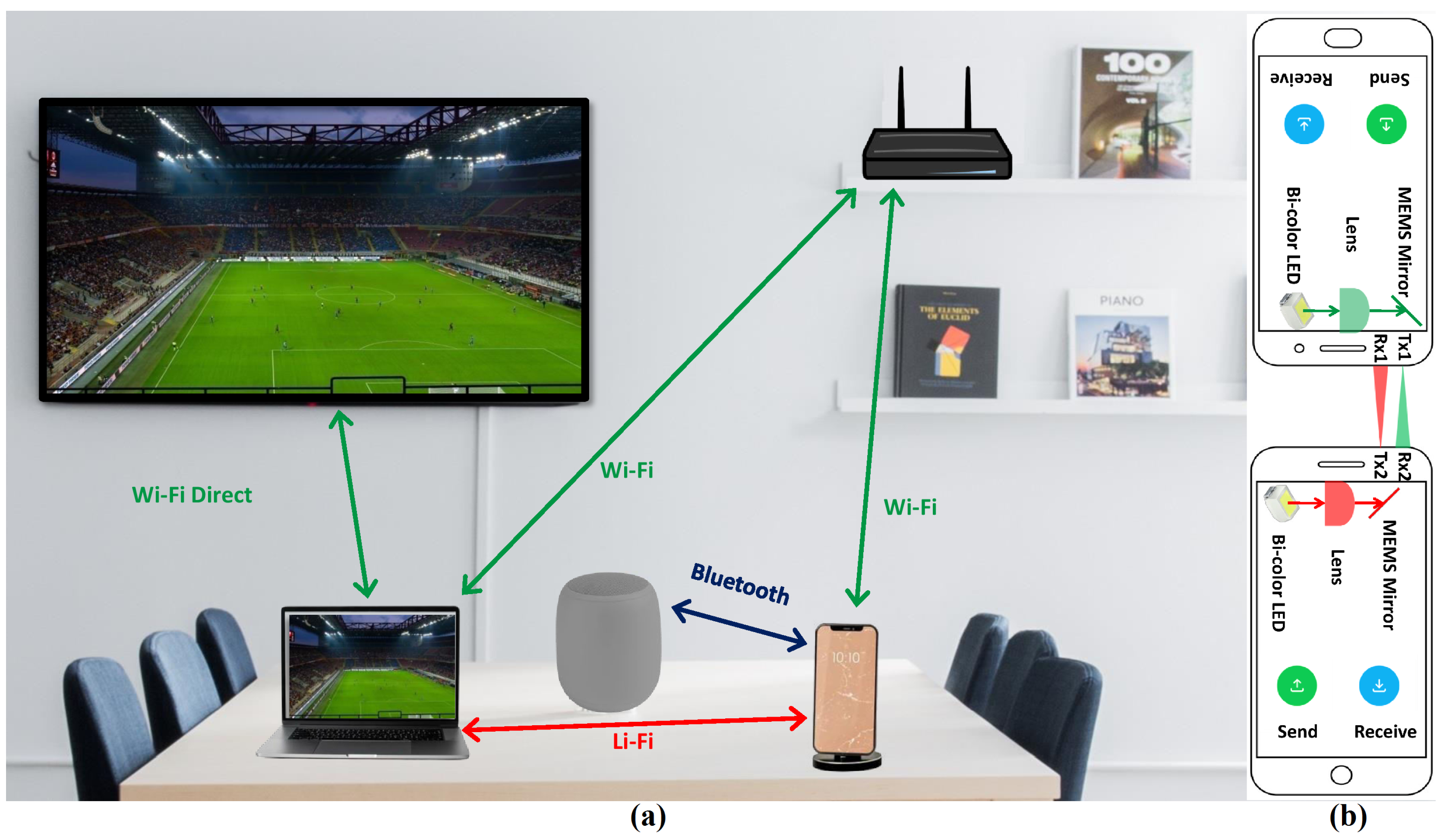
A new technology for high speed P2P communication can be an excellent additional feature for many consumer electronic products, especially for smartphones with use cases such as taking data backup and sending large files in a P2P communication ecosystem as shown in
Figure 1(a). VLC has the potential to support secure high-speed short distance M2M communication. Being dominantly a line of sight (LOS) technology, VLC offers a physical layer security and an eavesdropping attack would be almost impossible. Communication speeds beyond a few Gbits/s have already been achieved using off-the-shelf LEDs and laser diodes (LDs) as transmitters [
6]. In spite of these advantages and potential, the Gbits/s class VLC systems are too bulky due to the dependence of performance on lenses. In addition, small range and coverage are still important issues that need attention.
2.1. Coverage
Though VLC based M2M can offer higher transfer speed, the most important drawback of VLC is its LOS nature and small coverage as a result of that. With the current technology, the two devices must be within a few centimeter distance and properly aligned thus reducing the coverage area. As M2M communication must be a low power solution, the use of high power LED or LD to increase the coverage or range is not an option. A focused beam from a low power LED or LD along with a beam steering mechanism using a micro-electro-mechanical-system (MEMS) mirror can solve the small coverage problem as depicted in
Figure 1(b). In applications where Gbps class speed is not necessary, the current Wi-Fi direct technology is more practical. However, for large multimedia file transfer between smartphones and for taking data backup from old devices, VLC based M2M communication can be an attractive solution, especially for smartphone manufacturers to create a differentiator in their products. A hybrid VLC-RF communication ecosystem can also be a practical solution for seamless handover between WiFi direct and VLC depending on the speed demand and positions of the devices as shown in
Figure 1(a).
2.2. Form Factor
The high speed photo-diodes used as the receiver in VLC systems, have very small active areas, thus, being unable to collect a large amount of light without lenses. The sensitivity and noise performance of the state-of-art photo-diodes are also poor. Thus, researchers have used large lenses to focus as much light as possible onto the photo-diode’s active area. This improves the signal to noise ratio (SNR) and makes Gbits/s class VLC possible. However, a reduced form factor is a must for VLC implementation in portable devices.
The bulky lenses can be avoided if the distance between the transmitter and receiver is reduced. A Gbps class VLC system with a distance of a few centimeters along with the existing Wi-Fi direct can provide a robust M2M communication solution. When two devices are placed in close proximity and in line of sight, the VLC can support file transfers at Gbps speeds. When the VLC link is out of range, the M2M can switch to Wi-Fi direct supporting up to 250 Mbps data transfer.
A small form factor VLC transceiver without using bulky lenses is possible. A low power surface mounted red LED (Vishay VLMS1500-GS08) and a vertical-cavity surface-emitting laser (VCSEL Thorlabs L670VH1) have been tested as transmitters for comparison. The LED has a half power beam width of whereas the VCSEL has a circular Gaussian beam with a beam divergence of . The LED needs an aspheric lens for concentrating the diverging beam whereas the VCSEL does not need it. The receiver side should have an aspheric lens in front of the photo-diode for accumulating more light to improve the SNR. The diameter of the aspheric lens should be chosen keeping in mind the form factor of the device it aims to be adopted into. For a smartphone, for example, the lens diameter should not exceed the thickness of the smartphone which is typically below 10 mm. The modulation bandwidth of the selected LED is 300 MHz at dB and that of the VCSEL is 1000 MHz at dB. So, a speed in the order of a few Gbps is achievable using the VCSEL and the more cost effective LED can also attain the Gbps speed.
3. Indoor Localization
Indoor localization or positioning can be the most promising application of VLC. Visible light positioning (VLP) systems have applications both in consumer electronics and in the industrial sector. It may take time for consumer electronics industries to adopt VLP receivers in electronic gadgets. However, industrial warehouses and factories can implement and utilize VLP systems for automation without any dependency on any other shareholders. VLP systems do not require high speed (Gbits/s class) communications. More importantly, due to the line of sight nature of VLC, it can offer more reliable and accurate positioning information than other RF communication based alternatives available in the market. The indoor positioning systems based on RF technologies such as Zigbee, WiFi, Bluetooth, radio frequency identification (RFID), ultra-wideband (UWB), and 802.11az can not provide centimeter level accuracy [
7]. Moreover, they need extra hardware dedicated to positioning systems and suffer from multipath reflections. Whereas, the VLP transmitters are modified LED lights that serve the purpose of lighting as well. Performances of different indoor positioning technologies are compared in
Table 1. The popular positioning algorithms can be categorized in time of arrival (TOA), time difference of arrival (TDOA), received signal strength (RSS), and angle of arrival (AOA). The advantages of AOA-based systems over TOA, TDOA, and RSS are as follow: i) no need for complex time synchronization and ii) less susceptible to path loss, background noise, and multipath reflections.
VLP systems mainly use two types of receiver hardware: photo-diodes and cameras. Photo-diode offers higher bandwidth but it can provide reliable location information only when multiple photodiodes or multiple VLP transmitters are used. As multiple LOS connections may not be possible at all times, multiple photodiodes in a suitable arrangement can be the most practical receiver configuration. A single camera receiver on the other hand can provide location information from a single VLP transmitter but it is slow due to the small available bandwidth of camera hardware. However, the biggest advantage of using a camera as a VLP receiver is that cameras are already available in popular consumer electronics.
Hundreds of works on VLP systems have been published and many have achieved centimeter scale accuracy in location estimation [
8]. However, the less discussed issues in the available literature that need to be properly addressed to implement VLP systems in real-world situations are (i) Speed of position estimation (ii) Line of sight blockage and (iii) Height ambiguity.
3.1. Speed of Position Estimation
As the frame rate of commercial smartphone cameras is low, the camera-based VLP systems have utilized the rolling shutter effect of smartphone cameras to decode the transmitted information [
9]. The unique IDs of individual LED lights are decoded from the captured images. The method works well when the receiver is stationary. But, when the receiver is in the hand of a moving user, the image taken through the smartphone camera can be blurred due to the slow auto focus of budget CMOS sensors. The image processing can be slower for a fast moving user even in an indoor environment [
10]. The front facing camera in an average smartphone today has at least a few million pixels with each pixel commonly represented by 24 bits of color (RGB) information. The continuous processing of large size images consumes a lot of power and time. For VLP applications, black and white images of
resolution can be enough to estimate AOA if the transmitted signal is decoded with a high frame rate camera. The camera resolution and frame rate can not be increased together as it is limited by the image processing capability and DRAM buffer memory size of the sensor. A full HD (
) 30p video recording which is possible even in entry level smartphones today has a raw data rate of more than 186 MB/s. Large time delays to process this huge rate of information in real time may ruin the performance and user experience. Moreover, the rolling shutter effect cannot decode a large number of bits from a single frame when the LED transmitter is far away from the camera because only a small part of the frame captures the LED transmitter. On the other hand, a black and white,
resolution video at 5000 frames per second (fps) has a raw data rate of 25.9 MBytes/s. Low resolution high frame rate video can be generated from commercial CMOS camera sensors using the pixel skipping technique without any additional memory buffer. Pixel skipping is an effective and computationally less intensive technique to increase the frame rate by reducing image resolution. Pixel skipping is used to reduce the image resolution while maintaining the field of view by keeping one pixel in every
n pixel and discarding the rest
pixels where n can be any integer greater than 1.
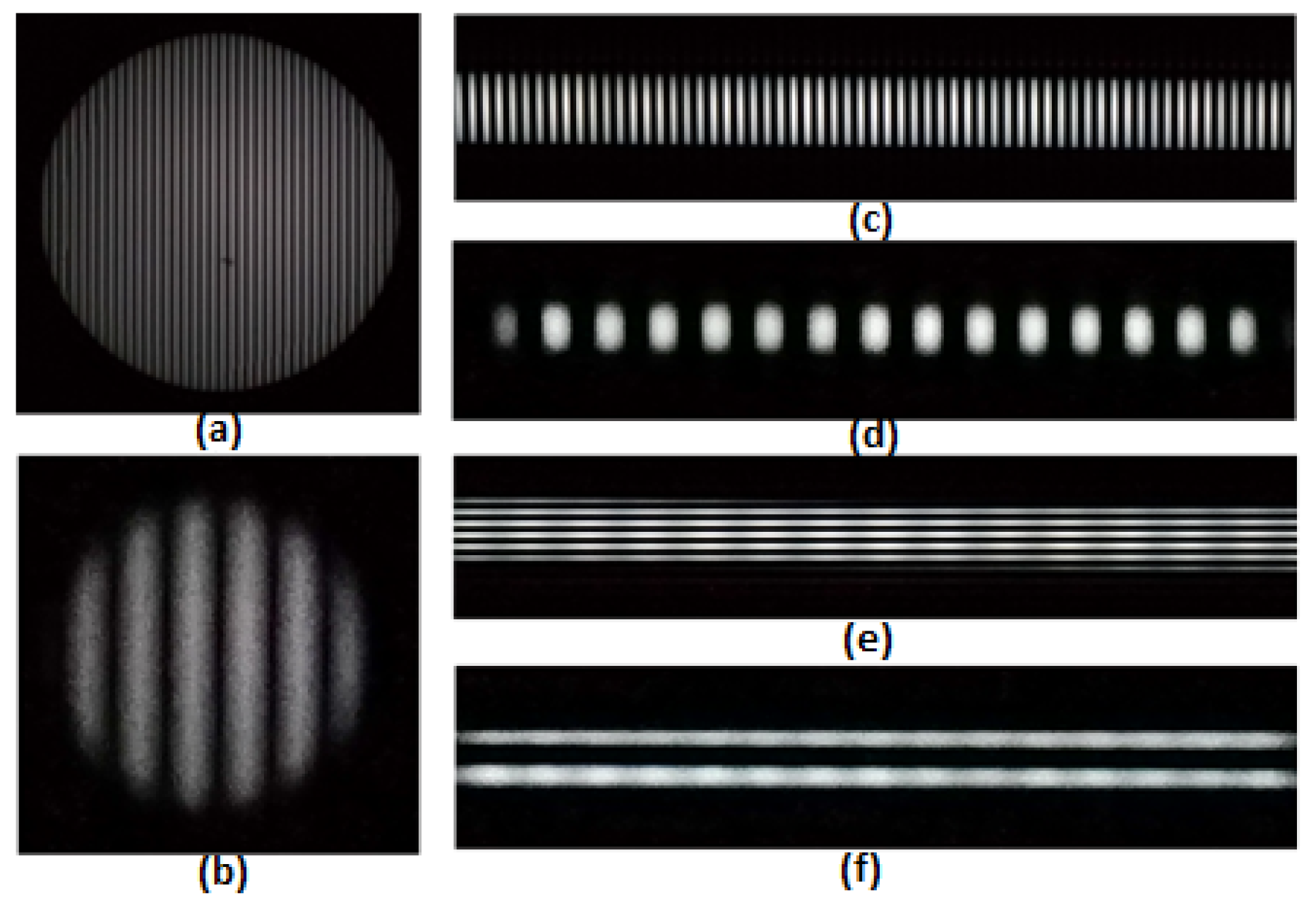
To bypass the limited frames per second of the low cost smartphone camera, most of the works have utilized the rolling shutter effect to capture the image and decode the transmitter IDs (TxID). The LED fringe images of a round and a linear panel LED light have been shown in
Figure 2(a). Though commercial smartphone camera has improved a lot with higher resolution over the last decade, the total number of pixels representing the LED light may not be enough to encode a long TxID, for example, tens of bits in a single frame. This scenario has been shown in
Figure 2(b) and
Figure 2(d). The problem becomes more serious when the camera is far away from the light and the size of the light fixture is small like a conventional light bulb. This is not a problem for a long LED light panel as presented in
Figure 2(c). However, the orthogonal alignment of the camera with the light will bring back the same issue as seen in
Figure 2(e) and
Figure 2(f). The only solution to these issues is to install a light panel with a larger length and width. However, that is an imposition on the lighting infrastructure as different indoor environments demand different shapes and sizes of lighting solutions. Moreover, when the user moves with the receiver (smartphone) in hand, proper focusing of the camera is hampered and the image can be ’shaky’ if the camera auto-focus is not fast enough. The inbuilt CMOS cameras of commercial smartphones do not allow taking photos or videos in very low resolution as there is no use of low resolution images in photography. However, for positioning applications, a future smartphone camera can be modified to allow very low resolution video recording at a higher frame rate with some software modification in the CMOS sensor image processor. In this article, an in-built camera of a commercial smartphone is used in slow motion HD (
) video mode (960 fps) to capture video of the two transmitter LEDs transmitting On-Off-Keying (OOK) modulated signal at 240 Hz and 192 Hz respectively to avoid any visible flicker. Then the captured video is converted into a low resolution (
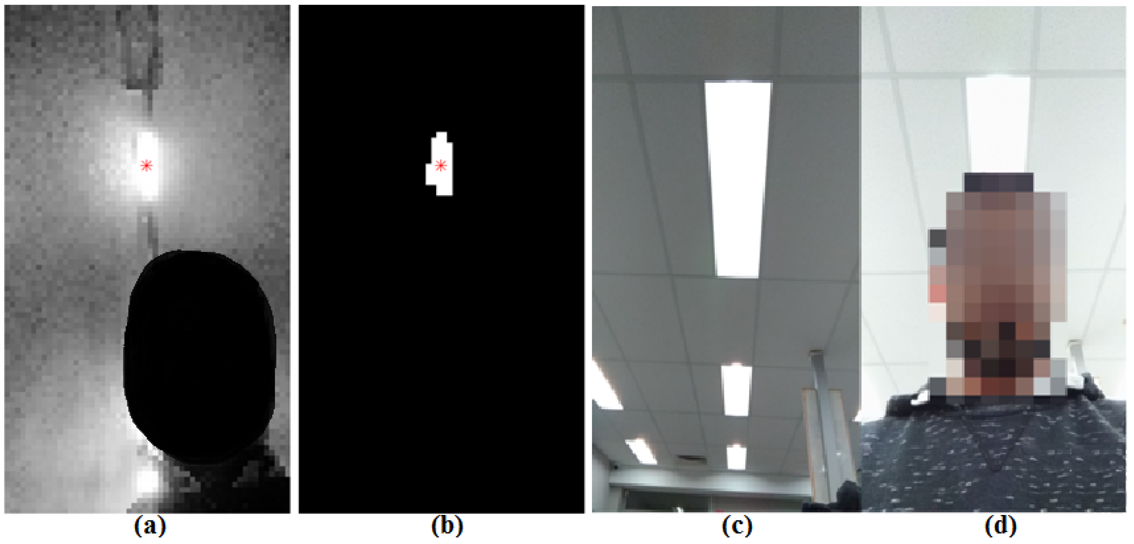
) video by pixel skipping (keeping one pixel and discarding the next nine pixels) and processed to extract the transmitter’s identification (TxID) and AOA information by finding the centroid of the light spot as shown in
Figure 3(a) and
Figure 3(b). The pixel skipping is performed to prove that a low resolution high frame rate information is useful for position estimation. It should be noted that a higher frame rate is possible if the inbuilt camera itself records the low resolution video in black and white format with lower bits per pixel depth. In this approach, it is also not necessary to have the entire light fixture in the image frame captured by the camera. Therefore, a low resolution high frame rate camera can be a practical solution for fast position estimation necessary for a moving person or an autonomous robot in indoor conditions.
3.2. Line of Sight Blockage
In most of the works on VLP systems, the VLP receiver has been placed on a robotic car to measure the experimental data. Other than autonomous robots in warehouses, even human beings can use the VLP system through a smartphone held in their hands. Part or the entire area of the light fixtures is generally blocked by the human body as a smartphone is held tilted towards the user. Such instances in an office cubicle environment are shown in
Figure 3(c) and
Figure 3(d). Only a part of one light fixture has been captured in this case with the user holding the tilted device. In addition, in practical scenarios, there can be many objects blocking the LOS signals from the VLP transmitters. In these cases, the TxID cannot be extracted from the image if a rolling shutter mechanism is utilized to receive the information. The problem of partial LED light blocking can be solved using low resolution high frame rate video because the entire light panel is not necessary to directly decode the transmitted signal.
3.3. Height Ambiguity
The majority of the VLP literature has considered two-dimensional (2D) position estimation assuming the height of the ceiling is known or fixed. However, in practical applications, the height of the ceiling from the receiver will vary for different buildings and with the user’s height and movements. To estimate the location in three-dimensional space, the height of the ceiling where the LED transmitter is installed must be measured in real time. Alternatively, LOS connections with multiple transmitters are necessary for 3D positioning which may not always be fulfilled especially in places where lights are sparsely installed or when LOS signals are blocked.
A low cost commercially available LIDAR sensor can be used to calculate the height of the transmitter LED from the VLP receiver to make the VLP system truly three-dimensional [
11]. In [
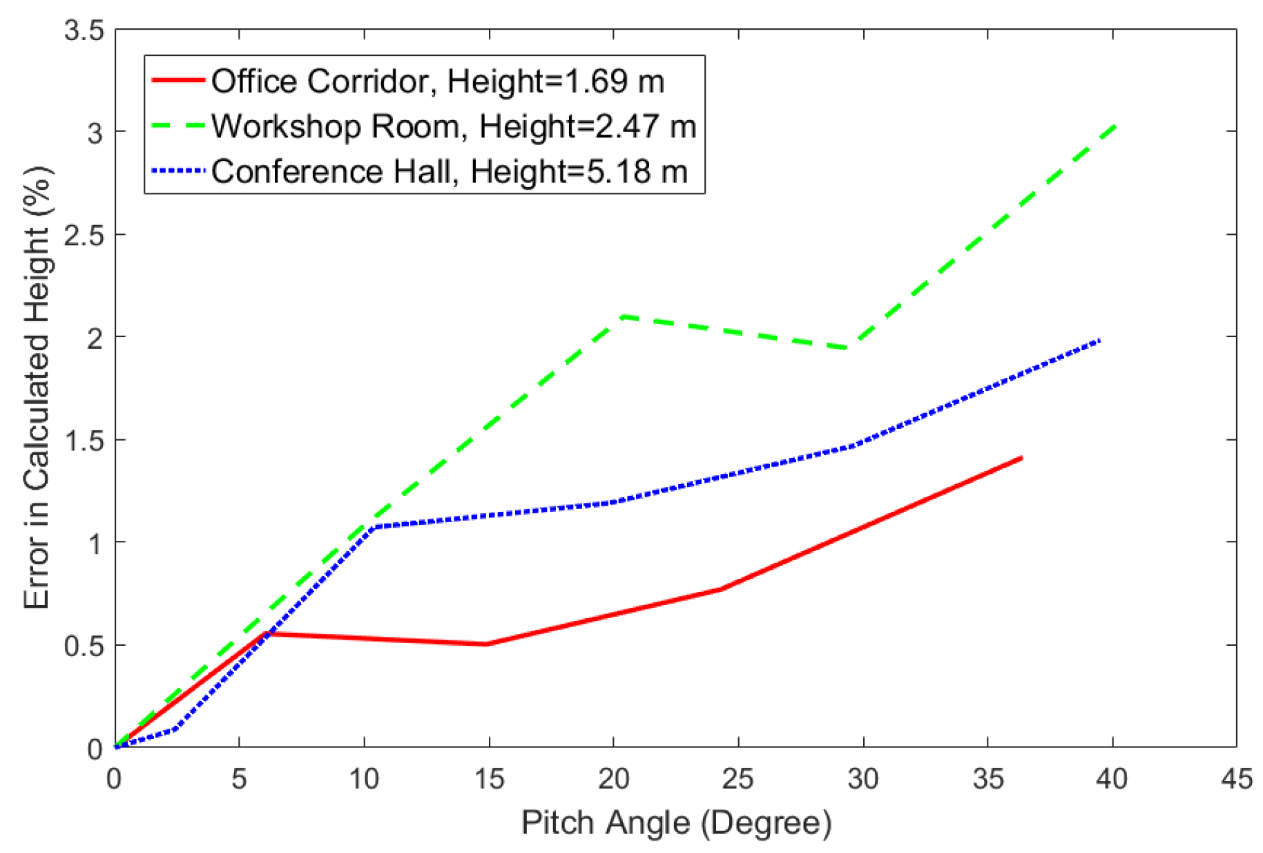
11], it has been shown that a low-cost LIDAR sensor can be very useful and accurate for 3D indoor positioning. It is assumed that the transmitter LED is installed at the ceiling. As the height of the ceiling in an area of a building does not change too abruptly, the LIDAR can be turned on at certain intervals to reduce the average power consumption. The LIDAR in this testing is based on the time of flight (TOF) principle and has an accuracy of up to 1 cm. As the LIDAR is proposed to be placed on the receiver, the tilt of the receiver must be considered while calculating the height of the ceiling. The height measurement is most accurate when it is placed horizontally. However, in the general case, the orientation changes with the user’s hand movement. The LIDAR sensor has been tested at different tilt angles in different indoor places. The height has been measured and the measurement error increases as the tilt angle increases as shown in
Figure 4. It is observed that the tilt angle varies from person to person and it also varies with time for the same person while walking. The pitch angle varies mainly between 10º to 45º. Though the error in height measurement at higher tilt angles is not serious, the results are unreliable in practical cases due to blockage by the user’s body at higher tilt angles. Therefore, the height corresponding to the minimum tilt angle should be taken into consideration while estimating the position as it is the most accurate height estimation.
4. Intelligent Transport Systems
VLC has promising applications in ITS including vehicle-to-vehicle (V2V) and vehicle-to-infrastructure (V2I) communications that are vital for improved road safety and autonomous cars [
12]. VLC-based ITS has the potential to improve traffic conditions and reduce road accidents through forward collision warnings, pre-crash sensing, emergency electronic brake lights, lane change warnings, stop sign movement assistance, turn assistant, traffic signal violation warnings, broadcasting, etc. As energy efficient LEDs are already being adopted both in most cars and in road infrastructure, VLC-based ITS has the advantage of lower implementation cost and faster market penetration. The LOS nature of VLC can be more beneficial for V2V communication due to reduced interference. However, the LOS nature of VLC dictates that the transmitter has to be in the field of view (FOV) of the receiver. Two critical aspects of VLC based V2V and V2I communications are: (a) choosing the right FOV and (b) preventing photo-diode saturation caused by unwanted light sources such as the sun and other artificial light sources on the road.
4.1. Field of View
In ITS, two types of receivers can be used for VLC: PD and Camera. PD can detect high bandwidth transmitted signals supporting high speed communications. As outdoor environments have more noise and interference in the system, the FOV of the PD is a very critical factor in ITS. While larger FOV covers more area and detects more information, it also adds more noise to the received signal thus degrading the communication performance. Smaller FOV on the other hand allows long distance communication but may miss out on transmitted signals from nearby sources that are out of FOV [
13]. Multiple PDs with different FOVs can be used as receivers to solve this issue [
14]. As PDs are not costly components, the added costs can be manageable for high value products like cars. Alternatively, liquid based, electronically variable focus lenses along with an artificial intelligence (AI) enabled camera can be used to receive signals for different FOVs from a single PD when required depending on the situation. The camera can be used to continuously scan the scene using AI to understand if there are interfering light sources or unwanted bright lights. The transmitter sends a signal multiple times and the PD receives the transmitted signal for different FOVs as shown in
Figure 5. The AI-enabled camera then can decide which signal has the minimum interference and maximum information and is to be processed for the best result. A camera based receiver can solve the FOV issue as the cameras have generally large FOV but cameras come with the inherent problem of low frame rate. A typical camera has frame rates below 100 fps and the rolling shutter property is not useful in long distance outdoor communication. Commercially available high frame rate cameras are costly and bulky and thus not practical for ITS. A photo-diode and camera hybrid sensor integrated into the same camera sensor has been tested by researchers for tracking car LED lights using the camera and receiving more than 50 Mbits/s data using photo-diodes [
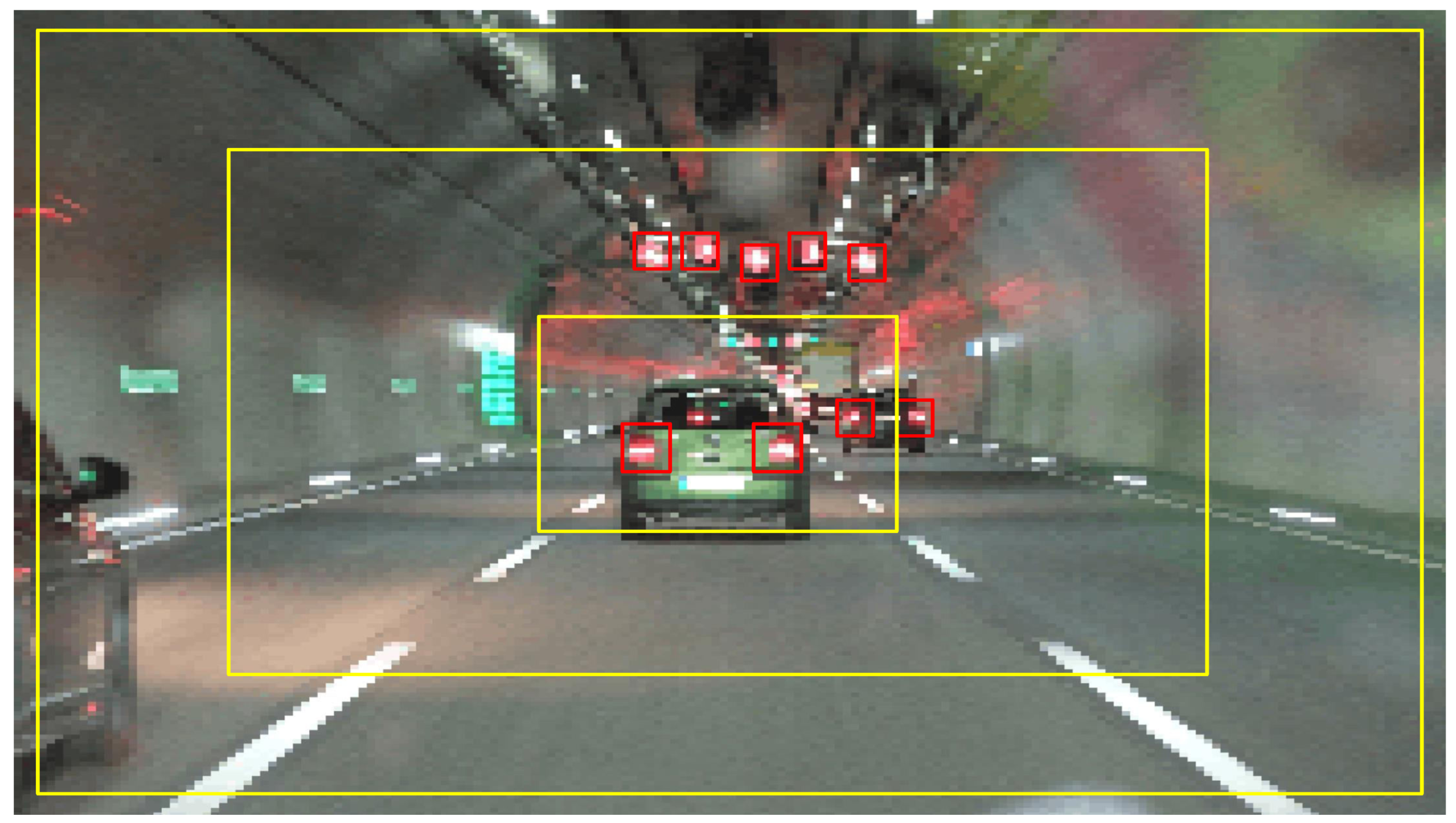
15]. However, the effectiveness of the system when the two cars are moving at different speeds and not aligned has to be tested. Low resolution high fps cameras can potentially solve the issue if the required data rate is not high. Lowering the camera resolution by a factor of 100 can allow a 100 times higher frame rate without increasing the computational complexity and still, the transmitted signal can be decoded from the low resolution video as seen in
Figure 5. As most modern cars are integrating multiple cameras in different positions, this also comes with the benefit of adding minimum hardware cost. The data from the cameras are also generally analyzed with computer vision. So, the received data both active and passive through VLC and computer vision respectively can improve the safety features of cars. As a result, cars with camera based-VLC systems do not need to wait for all the cars on the roads to be equipped with VLC systems which are not possible in a very short period of time.
4.2. Photo-Diode Saturation
In outdoor conditions, for PD based receivers, photo-diode saturation is another issue that degrades the received signal quality. Within the photo-diode FOV, if there is any unwanted bright light source such as the Sun, or headlights from other cars then the photo-diode gets saturated. Optical filters, to some extent, can prevent saturation by blocking unwanted wavelengths of incident light. A variable optical attenuator along with an automatic gain controller can potentially solve the issue [
16]. A variable FOV using a variable focus lens at the receiver can also help avoid PD saturation by dynamically adjusting the FOV depending on the outdoor conditions.
5. Conclusions
Current Gbps class VLC systems are bulky and offer LOS only, very short range, and small coverage communication. High speed alone cannot provide enough incentive to the consumers over the already matured yet fast evolving, ubiquitous, non-LOS, longer range Wi-Fi technology. However, the LOS nature, high spatial density and physical layer security of VLC systems can offer unique advantages in many applications. Indoor localization, ITS, and M2M communication are among the most suited commercial applications that can be implemented by the industries without any ’chicken and egg’ problem. The technical issues of these VLC applications have been highlighted and their best known and potential solutions are suggested. VLC can also be utilized in military wireless communications for higher security, and in underwater communications for lower attenuation compared to RF communication systems. More focus on commercializing VLC applications by the academic and industrial research community can pave the path for faster and deeper market penetration of VLC in the future.
References
- S. Rajagopal, R. D. Roberts, and S.-K. Lim, “Ieee 802.15. 7 visible light communication: modulation schemes and dimming support,” IEEE Communications Magazine, vol. 50, no. 3, pp. 72–82, 2012.
- E. Khorov, I. Levitsky, and I. F. Akyildiz, “Current status and directions of ieee 802.11 be, the future wi-fi 7,” IEEE access, vol. 8, pp. 88 664–88 688, 2020.
- A. Jovicic, J. Li, and T. Richardson, “Visible light communication: opportunities, challenges and the path to market,” IEEE communications magazine, vol. 51, no. 12, pp. 26–32, 2013.
- M. Collotta, G. Pau, T. Talty, and O. K. Tonguz, “Bluetooth 5: A concrete step forward toward the iot,” IEEE Communications Magazine, vol. 56, no. 7, pp. 125–131, 2018.
- W. Shen, B. Yin, X. Cao, L. X. Cai, and Y. Cheng, “Secure device-to-device communications over wifi direct,” IEEE Network, vol. 30, no. 5, pp. 4–9, 2016.
- L. Issaoui, S. Cho, and H. Chun, “High cri rgb laser lighting with 11-gb/s wdm link using off-the-shelf phosphor plate,” IEEE Photonics Technology Letters, vol. 34, no. 2, pp. 97–100, 2022.
- J. Luo, L. Fan, and H. Li, “Indoor positioning systems based on visible light communication: State of the art,” IEEE Communications Surveys & Tutorials, vol. 19, no. 4, pp. 2871–2893, 2017.
- B. Hussain, Y. Wang, R. Chen, and C. P. Yue, “Camera pose estimation using a vlc-modulated single rectangular led for indoor positioning,” IEEE Transactions on Instrumentation and Measurement, vol. 71, pp. 1–11, 2022.
- Y.-S. Kuo, P. Pannuto, K.-J. Hsiao, and P. Dutta, “Luxapose: Indoor positioning with mobile phones and visible light,” in Proceedings of the 20th annual international conference on Mobile computing and networking, 2014, pp. 447–458.
- P. Lin, X. Hu, Y. Ruan, H. Li, J. Fang, Y. Zhong, H. Zheng, J. Fang, Z. L. Jiang, and Z. Chen, “Real-time visible light positioning supporting fast moving speed,” Optics Express, vol. 28, no. 10, pp. 14 503–14 510, 2020.
- K. Bera, R. Parthiban, and N. Karmakar, “A truly 3d visible light positioning system using low resolution high speed camera, lidar, and imu sensors,” IEEE Access, 2023.
- S. A. Avătămăniței, A.-M. Căilean, A. Done, M. Dimian, and M. Prelipceanu, “Noise resilient outdoor traffic light visible light communications system based on logarithmic transimpedance circuit: experimental demonstration of a 50 m reliable link in direct sun exposure,” Sensors, vol. 20, no. 3, p. 909, 2020.
- S.-A. Avătămăniței, C. Beguni, A.-M. Căilean, M. Dimian, and V. Popa, “Evaluation of misalignment effect in vehicle-to-vehicle visible light communications: Experimental demonstration of a 75 meters link,” Sensors, vol. 21, no. 11, p. 3577, 2021.
- B. Aly, M. Elamassie, and M. Uysal, “Vehicular vlc system with selection combining,” IEEE Transactions on Vehicular Technology, vol. 71, no. 11, pp. 12 350–12 355, 2022.
- Y. Goto, I. Takai, T. Yamazato, H. Okada, T. Fujii, S. Kawahito, S. Arai, T. Yendo, and K. Kamakura, “A new automotive vlc system using optical communication image sensor,” IEEE photonics journal, vol. 8, no. 3, pp. 1–17, 2016.
- W. Liu, Z. Xu, and X. Jin, “Saturation compensation for visible light communication with off-the-shelf detectors,” Optics Express, vol. 29, no. 6, pp. 9670–9684, 2021.
|
Disclaimer/Publisher’s Note: The statements, opinions and data contained in all publications are solely those of the individual author(s) and contributor(s) and not of MDPI and/or the editor(s). MDPI and/or the editor(s) disclaim responsibility for any injury to people or property resulting from any ideas, methods, instructions or products referred to in the content. |
© 2024 by the authors. Licensee MDPI, Basel, Switzerland. This article is an open access article distributed under the terms and conditions of the Creative Commons Attribution (CC BY) license (https://creativecommons.org/licenses/by/4.0/).
