Submitted:
29 May 2024
Posted:
30 May 2024
You are already at the latest version
Abstract
Keywords:
1. Introduction
2. Materials and Methods
2.1. Mechanical Design of the Manipulator
2.1.1. Manipulator Technical Specification, Functional Design
- Number of DOF: 3 without wrist and gripper;
- overall dimensions, including actuators, contained in a cylinder with a diameter of 45 mm and a height of 140 mm;
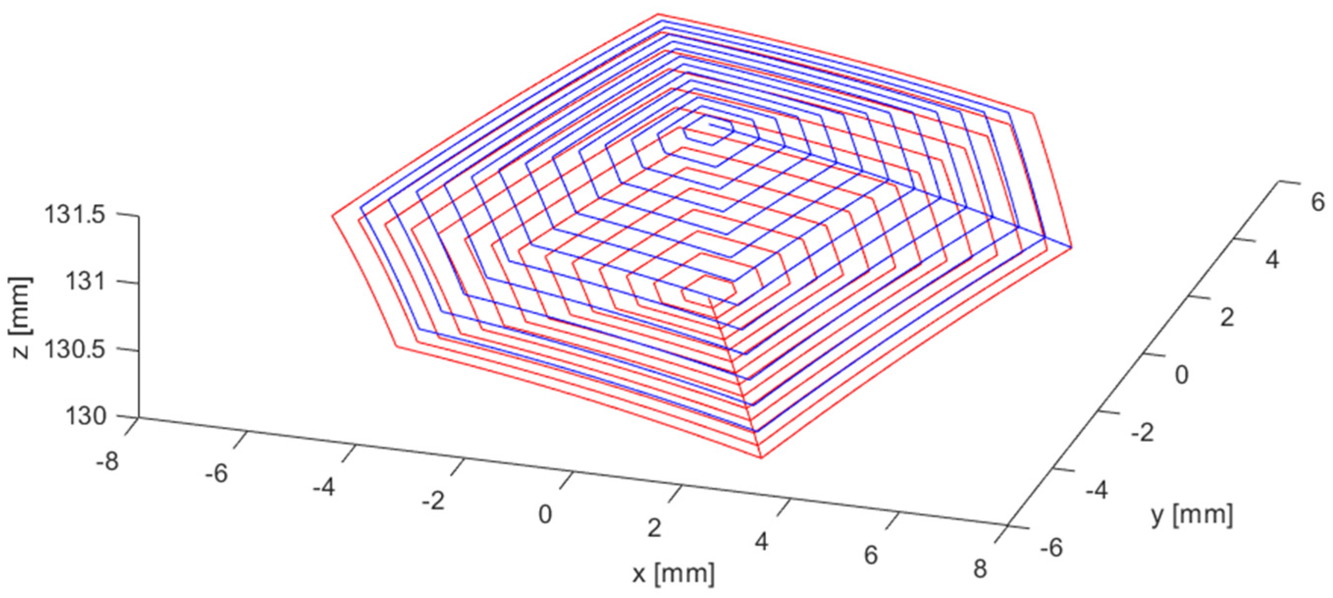
- diameter of the circle circumscribed to the plan projection of the working volume by height, in the range of 10 mm × 2 mm;
- actuator’s block control volume not more than 20000 mm3;
- overall mass without the electronics for control of not more than 0.05 kg;
- the manipulator is intended to manipulate tiny mass objects. So, the considered load capability is 0.05 N.
2.1.2. Characterization of Actuators Using Self-Sensing Effect
2.1.3. Direct Kinematic Model - Domain Analysis
2.1.4. Inverse Kinematic Model
2.1.5. Jacobian and Singularity Analysis
2.1.6. Dynamic Analysis - Actuators Dimensioning
2.1.7. Detailed Design
2.2. Control System
2.2.1. Hardware
2.2.2. Control Strategy
3. Results
3.1. Analysis of the Influence of Actuator Errors on Working Volume Errors
3.2. Manipulator Prototype
3.3. Experimental Tests
4. Discussion and Conclusion
Author Contributions
Funding
Data Availability Statement
Acknowledgments
Conflicts of Interest
References
- Kittinanthapanya, R.; Sugahara, Y.; Matsuura, D.; Takeda, Y. Development of a Novel SMA-Driven Compliant Rotary Actuator Based on a Double Helical Structure. Robotics 2019, 8, 12. [Google Scholar] [CrossRef]
- Britz, R.; Motzki, P.; Seelecke, S. Scalable Bi-Directional SMA-Based Rotational Actuator. Actuators 2019, 8, 60. [Google Scholar] [CrossRef]
- Copaci, D.; Blanco, D.; Moreno, L. Flexible Shape-Memory Alloy-Based Actuator: Mechanical Design Optimization According to Application. Actuators 2019, 8, 63. [Google Scholar] [CrossRef]
- Schmelter, T.; Theren, B.; Fuchs, S.; Kuhlenkötter, B. Development of an Actuator for Translatory Movement by Means of a Detented Switching Shaft Based on a Shape Memory Alloy Wire for Repeatable Mechanical Positioning. Crystals 2021, 11, 163. [Google Scholar] [CrossRef]
- Ballester, C.; Copaci, D.; Arias, J.; Moreno, L.; Blanco, D. Hoist-Based Shape Memory Alloy Actuator with Multiple Wires for High-Displacement Applications. Actuators 2023, 12, 159. [Google Scholar] [CrossRef]
- Durante, F.; Beomonte Zobel, P.; Raparelli, T. The experience at University of L’Aquila on shape memory alloys actuators. In Advances in Service and Industrial Robotics; Mechanisms and Machine Science; Springer, Cham, Switzerland, 2018, Volume 49, pp. 638–645. [CrossRef]
- Dauksher, R.; Patterson, Z.; Majidi, C. Characterization and Analysis of a Flexural Shape Memory Alloy Actuator. Actuators 2021, 10, 202. [Google Scholar] [CrossRef]
- Ameduri, S.; Concilio, A.; Favaloro, N.; Pellone, L. A Shape Memory Alloy Application for Compact Unmanned Aerial Vehicles. Aerospace 2016, 3, 16. [Google Scholar] [CrossRef]
- Bovesecchi, G.; Corasaniti, S.; Costanza, G.; Tata, M. A Novel Self-Deployable Solar Sail System Activated by Shape Memory Alloys. Aerospace 2019, 6, 78. [Google Scholar] [CrossRef]
- Liu, M.; Wang, Z.; Ikeuchi, D.; Fu, J.; Wu, X. Design and Simulation of a Flexible Bending Actuator for Solar Sail Attitude Control. Aerospace 2021, 8, 372. [Google Scholar] [CrossRef]
- Costanza, G.; Delle Monache, G.; Tata, M.; Filosi, S. Development of SMA Spring Linear Actuator for an Autonomous Lock and Release Mechanism: Application for the Gravity-Assisted Pointing System in Moon to Earth Alignment of Directional Devices. Aerospace 2022, 9, 735. [Google Scholar] [CrossRef]
- Dimino, I.; Vendittozzi, C.; Reis Silva, W.; Ameduri, S.; Concilio, A. A Morphing Deployable Mechanism for Re-Entry Capsule Aeroshell. Appl. Sci. 2023, 13, 2783. [Google Scholar] [CrossRef]
- Braun, D.; Weik, D.; Elsner, S.; Hunger, S.; Werner, M.; Drossel, W. Position Control and Force Estimation Method for Surgical Forceps Using SMA Actuators and Sensors. Materials 2021, 14, 5111. [Google Scholar] [CrossRef] [PubMed]
- Kim, H.; Jang, S.; Do, P.; Lee, C.; Ahn, B.; Kwon, S.; Chang, H.; Kim, Y. Development of Wearable Finger Prosthesis with Pneumatic Actuator for Patients with Partial Amputations. Actuators 2023, 12, 434. [Google Scholar] [CrossRef]
- Deng, E.; Tadesse, Y. A Soft 3D-Printed Robotic Hand Actuated by Coiled SMA. Actuators 2021, 10, 6. [Google Scholar] [CrossRef]
- Kotb, Y.; Elgamal, I.; Serry, M. Shape Memory Alloy Capsule Micropump for Drug Delivery Applications. Micromachines 2021, 12, 520. [Google Scholar] [CrossRef] [PubMed]
- Shen, J.; Chen, Y.; Sawada, H. A Wearable Assistive Device for Blind Pedestrians Using Real-Time Object Detection and Tactile Presentation. Sensors 2022, 22, 4537. [Google Scholar] [CrossRef] [PubMed]
- Copaci, D.; Serrano, D.; Moreno, L.; Blanco, D. A High-Level Control Algorithm Based on sEMG Signalling for an Elbow Joint SMA Exoskeleton. Sensors 2018, 18, 2522. [Google Scholar] [CrossRef] [PubMed]
- He, J.; Lu, Y.; Wang, L.; Ma, N. On the Improvement of Thermal Protection for Temperature-Responsive Protective Clothing Incorporated with Shape Memory Alloy. Materials 2018, 11, 1932. [Google Scholar] [CrossRef] [PubMed]
- Srivastava, R.; Alsamhi, S.; Murray, N.; Devine, D. Shape Memory Alloy-Based Wearables: A Review, and Conceptual Frameworks on HCI and HRI in Industry 4.0. Sensors 2022, 22, 6802. [Google Scholar] [CrossRef] [PubMed]
- Lee, J.; Han, M. Design and Evaluation of Smart Textile Actuator with Chain Structure. Materials 2023, 16, 5517. [Google Scholar] [CrossRef]
- Helps, T.; Vivek, A.; Rossiter, J. Characterization and Lubrication of Tube-Guided Shape-Memory Alloy Actuators for Smart Textiles. Robotics 2019, 8, 94. [Google Scholar] [CrossRef]
- Raparelli, T.; Zobel, P.B.; Durante, F. A proposed methodology for the development of microgrippers: An application to a silicon device actuated by shape memory alloy wires. Int. J. Mech. Eng. Technol. 2018, 9, 235–249. [Google Scholar]
- Zainal, M.; Sahlan, S.; Ali, M. Micromachined Shape-Memory-Alloy Microactuators and Their Application in Biomedical Devices. Micromachines 2015, 6, 879–901. [Google Scholar] [CrossRef]
- Garcés-Schröder, M.; Hecht, L.; Vierheller, A.; Leester-Schädel, M.; Böl, M.; Dietzel, A. Micro-Grippers with Femtosecond-Laser Machined In-Plane Agonist-Antagonist SMA Actuators Integrated on Wafer-Level by Galvanic Riveting. Proceedings 2017, 1, 385. [Google Scholar] [CrossRef]
- Subendran, S.; Kang, C.; Chen, C. Comprehensive Hydrodynamic Investigation of Zebrafish Tail Beats in a Microfluidic Device with a Shape Memory Alloy. Micromachines 2021, 12, 68. [Google Scholar] [CrossRef]
- Maffiodo, D.; Raparelli, T. Flexible Fingers Based on Shape Memory Alloy Actuated Modules. Machines 2019, 7, 40. [Google Scholar] [CrossRef]
- Zeng, X.; Wu, Y.; Han, S.; Liu, Y.; Xiu, H.; Tian, F.; Ren, L. Theoretical and Experimental Investigations into a Crawling Robot Propelled by Piezoelectric Material. Micromachines 2021, 12, 1577. [Google Scholar] [CrossRef]
- Perez-Sanchez, V.; Garcia-Rubiales, F.; Nekoo, S.; Arrue, B.; Ollero, A. Modeling and Application of an SMA-Actuated Lightweight Human-Inspired Gripper for Aerial Manipulation. Machines 2023, 11, 859. [Google Scholar] [CrossRef]
- Raparelli T., Beomonte Zobel P., Durante F. Mechanical design of a 3-dof parallel robot actuated by smart wires. (2009) Proceedings of EUCOMES 2008 - The 2nd European Conference on Mechanism Science, pp. 271 - 278. [CrossRef]
- Shin, J.; Han, Y.; Lee, J.; Han, M. Shape Memory Alloys in Textile Platform: Smart Textile-Composite Actuator and Its Application to Soft Grippers. Sensors 2023, 23, 1518. [Google Scholar] [CrossRef]
- Shi, L.; Guo, S.; Li, M.; Mao, S.; Xiao, N.; Gao, B.; Song, Z.; Asaka, K. A Novel Soft Biomimetic Microrobot with Two Motion Attitudes. Sensors 2012, 12, 16732–16758. [Google Scholar] [CrossRef]
- Rajagopalan, R.; Petruska, A.; Howard, D. A Bi-State Shape Memory Material Composite Soft Actuator. Actuators 2022, 11, 86. [Google Scholar] [CrossRef]
- Maffiodo, D.; Raparelli, T. Three-fingered gripper with flexure hinges actuated by shape memory alloy wires. Int. J. Autom. Technol. 2017, 11, 355–360. [Google Scholar] [CrossRef]
- Sreekumar M., Singaperumal M., Nagarajan T., Zoppi M., Molfino R. A compliant miniature parallel manipulator with shape memory alloy actuators (2006) Proceedings of the IEEE International Conference on Industrial Technology, art. no. 4237692, pp. 848 - 853. [CrossRef]
- Elwaleed A.K., Mohamed N.A., Nor M.J.M., Mustafa M.M. A new method for actuating parallel manipulators (2008) Sensors and Actuators, A: Physical, 147 (2), pp. 593 - 599. [CrossRef]
- Giuseppe C. Experimental characterization of a binary actuated parallel manipulator (2016) Chinese Journal of Mechanical Engineering (English Edition), 29 (3), pp. 445 - 453. [CrossRef]
- AbuZaiter A., Ng E.L., Kazi S., Mohamed Ali M.S. Development of Miniature Stewart Platform Using TiNiCu Shape-Memory-Alloy Actuators (2015) Advances in Materials Science and Engineering, 2015, art. no. 928139. [CrossRef]
- Ranjith Pillai, R. , Ganesan M. Mechatronics Design and Kinematic Analysis of SMA Spring Actuated Parallel Manipulator (2021) Journal of Physics: Conference Series, 1969 (1), art. no. 012011. [CrossRef]
- Raparelli T., Zobel P.B., Durante F. Design of a parallel robot actuated by shape memory alloy wires. (2002) Materials Transactions, 43 (5), pp. 1015 - 1022. [CrossRef]
- Raparelli, T.; Beomonte Zobel, P.; Durante, F. A robot actuated by shape memory alloy wires. In Industrial Electronics, 2002. ISIE 2002, Proceedings of the 2002 IEEE International Symposium on, L’Aquila, Italy, 8–11 July 2002; IEEE: Piscataway, NJ, USA, 2002; Volume 2, pp. 420–423. [Google Scholar] [CrossRef]
- Durante F., Raparelli T., Beomonte Zobel P. Resistance Feedback of a Ni-Ti Alloy Actuator at Room Temperature in Still Air (2024) Micromachines, 15 (4), art. no. 545. [CrossRef]
- Gosselin C., Angeles J. Singularity Analysis of Closed-Loop Kinematic Chains (1990) IEEE Transactions on Robotics and Automation, 6 (3), pp. 281 - 290. [CrossRef]



| Flexinol 150HT |
|---|
| Wire diameter: 150 µm |
| Linear resistance: 50 Ω/m |
| Maximum recovery force: 10.4 N |
| Recommended deformation ratio: 3-5 % |
| Austenite start temperature: 68°C |
| Austenite finish temperature: 78°C |
| Martensite start temperature: 52°C |
| Martensite finish temperature: 42°C |
| b (mm) | aM (°) | am (°) | OPM (mm) | OPm (mm) | D(OP) (mm) |
|---|---|---|---|---|---|
| 10.00 | 60.00 | 58.79 | 17.32 | 16.51 | 0.81 |
| 11.00 | 56.63 | 55.25 | 16.70 | 15.86 | 0.84 |
| 12.00 | 53.13 | 51.56 | 16.00 | 15.12 | 0.88 |
| 13.00 | 49.46 | 47.66 | 15.20 | 14.26 | 0.93 |
| 14.00 | 45.57 | 43.50 | 14.28 | 13.28 | 1.00 |
| 15.00 | 41.41 | 38.99 | 13.23 | 12.14 | 1.08 |
| 16.00 | 36.87 | 34.00 | 12.00 | 10.79 | 1.21 |
| 16.50 | 34.41 | 31.25 | 11.30 | 10.01 | 1.29 |
| 17.00 | 31.79 | 28.26 | 10.54 | 9.14 | 1.40 |
| 18.00 | 25.84 | 21.15 | 8.72 | 6.96 | 1.75 |
| 19.00 | 18.19 | 10.12 | 6.24 | 3.39 | 2.86 |
| Device | DOF | WV | PA | OD | ABV | M |
|---|---|---|---|---|---|---|
| (a) | 3 | 12 × 2 | 0.3 | 82 × 207 | 138600 | 0.245 |
| (b) | 3 | 12 × 1.3 | 1/0.3 | 40.8 × 120 | 7844 | 0.012 |
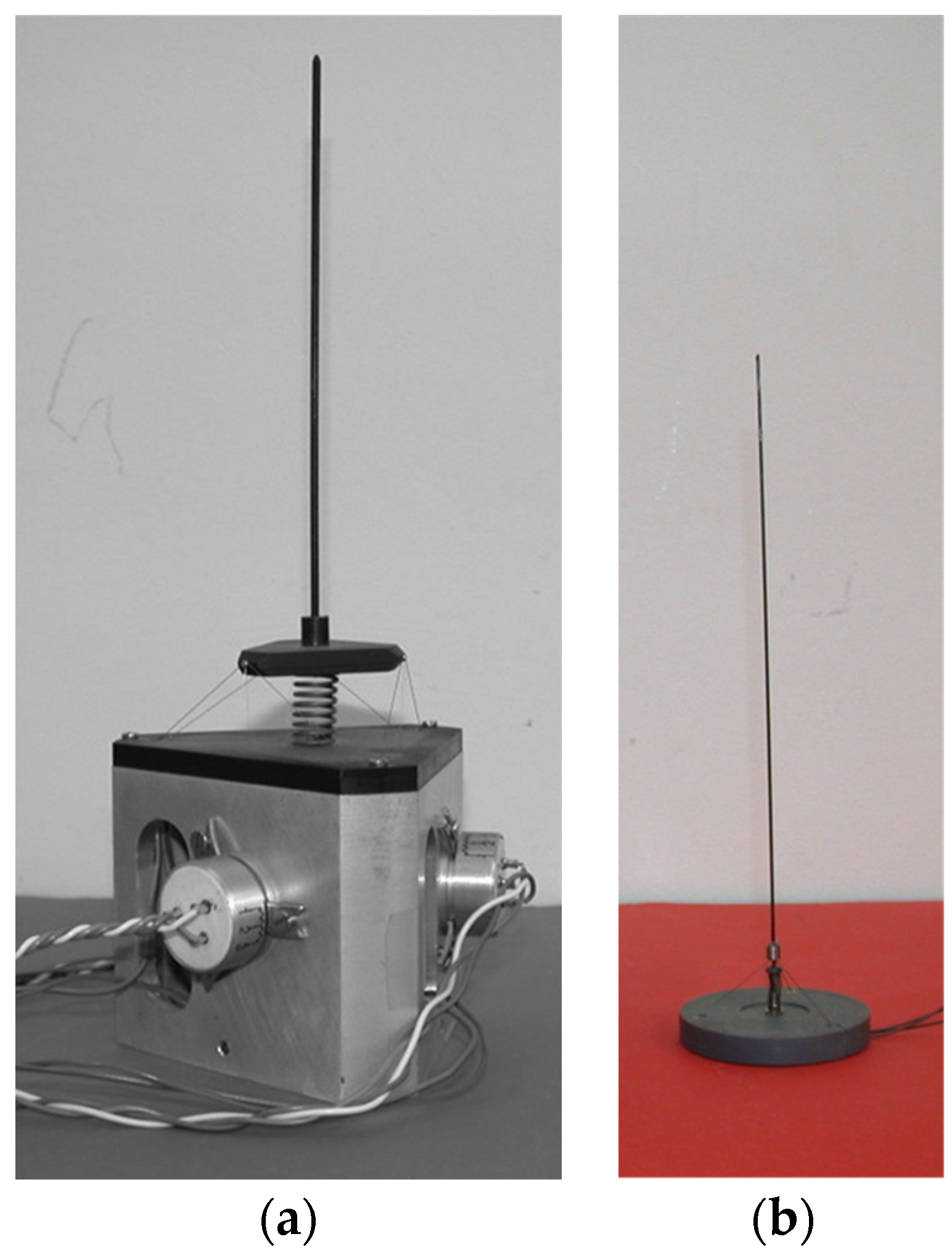
| (c) | 3 | 10 × 2 | 0.1 | 45 × 140 | 20000 | 0.050 |
Disclaimer/Publisher’s Note: The statements, opinions and data contained in all publications are solely those of the individual author(s) and contributor(s) and not of MDPI and/or the editor(s). MDPI and/or the editor(s) disclaim responsibility for any injury to people or property resulting from any ideas, methods, instructions or products referred to in the content. |
© 2024 by the authors. Licensee MDPI, Basel, Switzerland. This article is an open access article distributed under the terms and conditions of the Creative Commons Attribution (CC BY) license (http://creativecommons.org/licenses/by/4.0/).


