1. Introduction
Development of digital microprocessors (µP) started in the 1970s; since then a growth rate in performance of about one order of magnitude every 4 to 5 years has been observed. Volume and power needed for a computer system stayed about the same so that the system could fit into a (road) vehicle. When the author in 1975 received a call to a newly founded university in Munich he decided around 1980 to build a ‘Hardware-In-the-Loop’ (HIL) simulation laboratory for developing the sense of vision for vehicles. This unusual step has paid off in the next decades. The first PhD-thesis on vision for a road vehicle with this simulation loop appeared in 1982 [
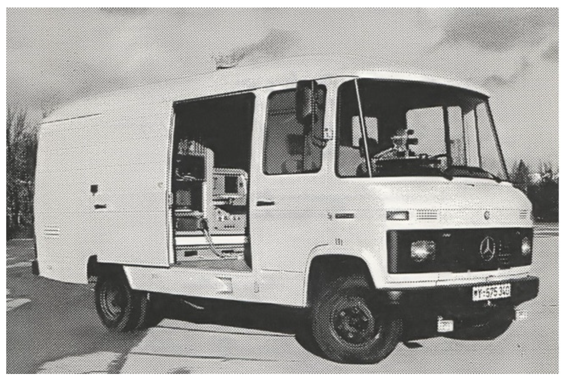
1]. In 1984 the first real test vehicle, a 5-ton van was purchased and equipped as test vehicle for autonomous mobility and computer vision: VaMoRs (
Figure 1). In 1987 it drove fully autonomously on a free stretch of the new Autobahn A94 near Dingolfing with speeds up to the maximum speed of the vehicle: 96 km/h. After this demonstration, computer vision was accepted for both longitudinal and lateral control in the EUREKA-project PROMETHEUS from 1987 till 1994 replacing electromagnetic fields from buried cables for lateral guidance.
After the successful midterm demo 1991 in Torino with van-type vehicles, the up to then skeptical top management level of the car manufacturing company Daimler-Benz AG (DBAG) asked for a system in a passenger car for the final demo in 1994 near Paris with the request to have passengers onboard the vehicle. We promised to try this if twenty researchers could be funded by the project. To our surprise the project was granted, and two Mercedes 500-SEL were selected as test vehicles, one each for DBAG and UniBwM. DBAG took care of all mechanical changes necessary in both vehicles, and UniBwM developed the vision system and all software necessary for autonomous driving with the new ‘Transputer’-system consisting of up to sixty processors.
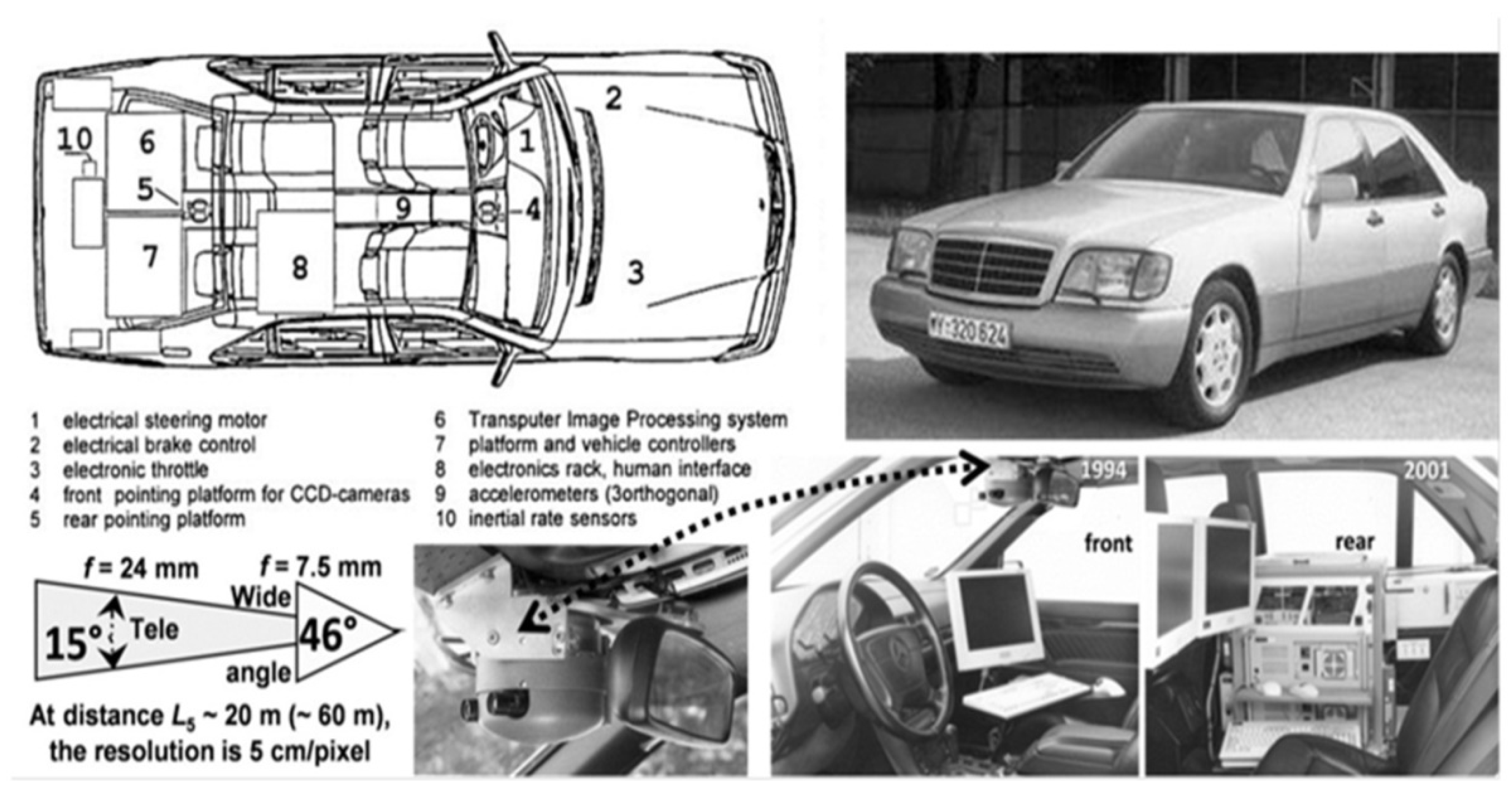
Figure 2 shows a survey on the UniBwM-system VaMP (short for VaMoRs-PKW). Both vehicles were the only ones capable of driving autonomously in public three-lane traffic at speeds up to the maximum speed allowed in France of 130 km/h. Free driving, lane changing and convoy-driving have been demonstrated [2a) to 2e)].
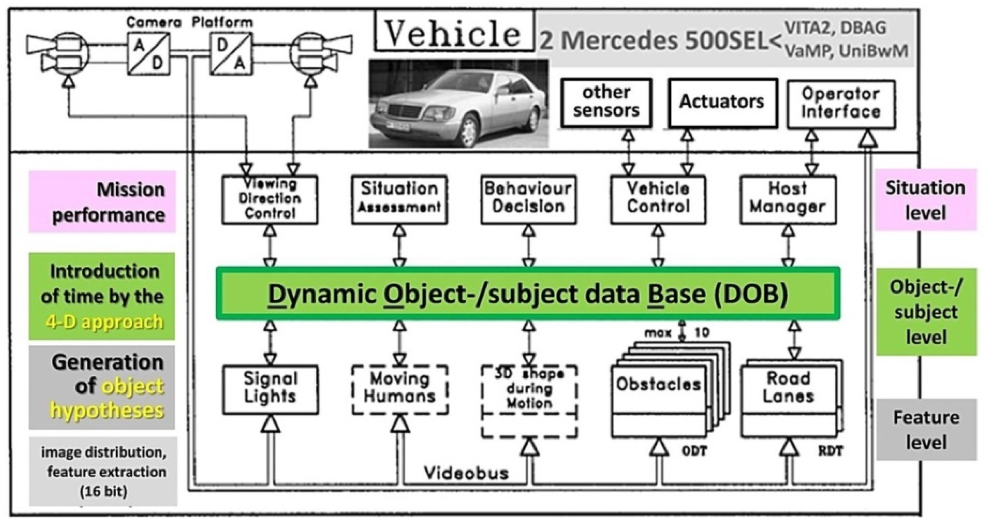
The structure of the second-generation vision system is shown in
Figure 3. On the right-hand side it shows the three levels with separate knowledge bases. Gray at the bottom for feature extraction and the generation of 3-D object hypotheses; green: for objects and subjects with the introduction of time by the 4-D approach, and red: for situation assessment and mission performance. Up to ten other vehicles could be detected and tracked in the own and the two neighboring lanes [
3]. In total, more than 1000 km have been driven autonomously.
In the following year 1995 the transputer system has been replaced by more modern PC-processors with ten times the computing power. This then allowed running the system at full video speed (40 ms cycle time instead of 80 before) on only 1/5 the number of processors. With forward-looking cameras only, the fully autonomous long-distance test drive Munich – Odense – Munich has been performed in Nov. 1995 [4; 5 (sect. 9.4.2.5)]
At the end of 1996 the cooperation with DBAG was ended since a new project in cooperation with US-American partners in the framework of an existing Memorandum of Understanding between the Departments of Defense was launched. The goal of the joint project AutoNav was to develop a next-generation vision system based on the 4-D approach capable of driving in networks of minor roads with sequences off-road; in addition to obstacles above the driving plane, also negative obstacles (ditches) should be detected and avoided autonomously.
The development of the PC-market had advanced in the meantime so that standard systems allowed building real-time vision systems by creating new software systems only. What should be the essential characteristics of our third-generation vision system?
2. Three Characteristics on Which the Name EMS-Vision is Based
2.1. Extension of the 4-D Approach to Covering Maneuvers and Missions: Expectations
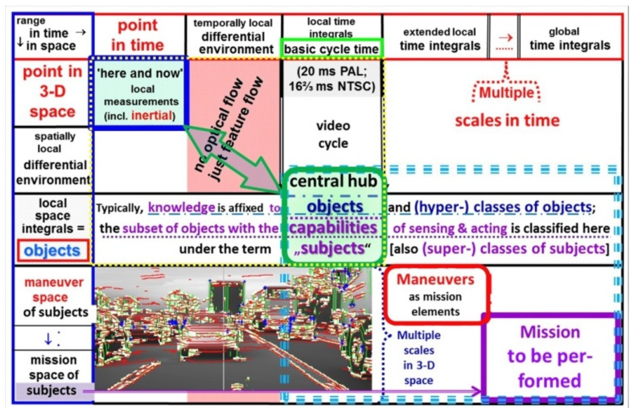
Systematic exploitation of characteristics over time as fourth dimension was the first goal: The local relations within the dotted yellow rectangle (upper left corner in
Figure 4) are exploited in the 4-D approach through spatiotemporal models (differential equations) for feedback of prediction errors in order to adjust both state variables of the objects observed and parameters in the models used. The mission to be performed (in the lower right corner) is considered as sequence of maneuvers, each consisting maybe of several maneuver elements. Capabilities for executing these maneuvers and missions can only be achieved by special time histories of control variables available in the real system. As far as the own body of the acting subject is concerned, these relations are part of a special knowledge base the subject has to learn. Since this action for control of motion is quite separate from perception, a special knowledge base for control of motion has been selected. It does not have to store the full trajectories of state variables but may be confined to just the time histories of the control variables involved leading to the desired final state.
In
Figure 4 the dotted blue rectangle in the lower right shows this extension in space and time by the diagonal from the center to bottom right. In the lower left corner a road scene with dense traffic is depicted not by an image consisting of pixels but by just five types of features yielding the same impression: White: image regions with nonlinear intensity changes in orthogonal directions; inclined edges found by vertical (red) and horizontal (green) search with special edge models according to [6; 5 (chapter 5.2)]; blue crosses: intensity corners; and in gray: linearly changing image intensity values [
7]. For a human observer of this artificial image of a scene, a correct interpretation is immediate. Even the number of several relevant objects on the three-lane road with their approximate distances will be recognized starting from nearby in the lowest row.
2.2. Why Multi-Focal Sets of Cameras
Due to perspective projection and the gaze direction almost parallel to the ground, a pair of parallel lines on a planar ground (representing an idealized road) with the camera at the center of the near end is mapped into a triangle in the image with the tip at the far end (above the ground line nearby). The field of view of a sequence of single rows in the image of a camera also is a triangle, but with the tip in the camera. Since light rays are straight, a pixel in the image that transversally covers 1 cm at a distance of 10 m will cover 0.2 m at 200 m and even 2 m at 2 km range. A vehicle of 2 m width will be covered by 200 pixels in one line at a range of 10 m and by ten pixels at 200 m; at a distance of 2 km, the width of such a vehicle is covered by a single pixel so that the features of one vehicle are averaged away. This clearly shows that for understanding images of extended outdoor scenes, different resolutions should be used for imaging parts of the scene depending on the distance imaged and analyzed. This fact calls for multi-focal sets of cameras, at best with active control of gaze direction (see [
8]).
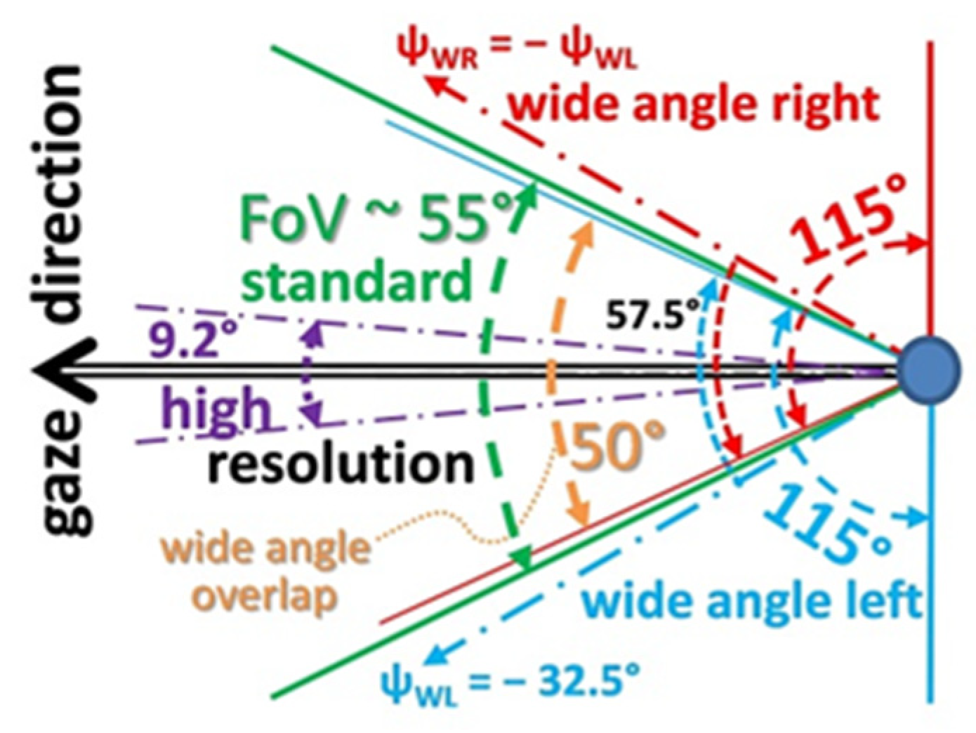
Experience in the past with a bifocal set of cameras has shown that in order to find the same region in the two images efficiently, the ratio in focal lengths should not exceed one order of magnitude. A factor of six to seven has been found a good compromise, but the smaller the ratio is, the easier it is to find the precise correspondence between image points. A ‘vehicle-eye’ with four cameras according to
Figure 5 has been proposed in [
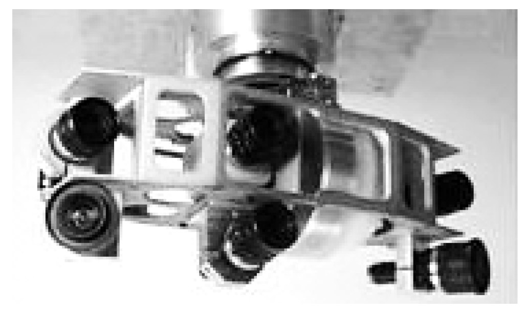
8]. Since one American partner in the AutoNav project contributed a new stereo vision system with two parallel-looking cameras, the configuration tested earlier looked like shown in
Figure 6 with the stereo pair above the divergent-looking wide-angle cameras. At the center are the cameras with a standard field of view (FoV) and with high resolution.
The size of a modern ‘vehicle eye’ would be one to two orders of magnitude smaller than the test set shown here (see e.g., handy-cameras available actually). The request in resolution for the high-resolution camera of such an eye is: It should be able to make printed text readable with acuity of edge localization of about 0.2 mrad/pixel (slightly better than human performance). With 800 pixels per row, the image then covers an angle of about 9.2° laterally. At 10 m distance the lateral range covered by the camera is ~ 2.6 m with coverage of ~3.3 mm/pixel; at 200 m distance the lateral range covered in the image will be ~ 50 m with 2 pixel/0.13 m. This is sufficient for recognizing the lane boundaries or the road limits marked by bright lines of say 0.12 m width. A divided highway with two lanes in each direction and one parking lane to the side may have a width of 20 to 30 m. So, at 200 m distance just about twice the width of the highway is covered with high resolution. According to
Table 1 (row 3) the total spread in resolution is twelve; the lateral fields of view in degrees are 9.2 for high, 55 for medium, and 115 for low resolution selected.
| Table 1 |
| Type (resolution) |
Low |
medium |
high |
remark |
| Fields of view (in °) |
115 × 62 |
55 × 31 |
9.2 × 9.2 |
Left (-) and right (+) for ‘low’ |
| Imaging characteristics (resolution) |
2.4
¼ of med. |
0.6
⅓ of high |
0.2 |
mrad/pixel,
acuity of edge localization |
| Pixels / line |
800 |
1600 |
800 |
These are rough estimates according to a pinhole model |
| Number of lines |
450 |
900 |
800 |
| Data volume/frame |
2.16 MB |
4.32 MB |
1.92 MB |
3 Bytes/pixel; sum = 8.4 MB/cycle |
At a road crossing, the wide-angle camera should yield information on both roads intersecting at an approximately right angle. In [
8] also a vision sensor covering the entire environment at different resolutions but mounted fix onto the body of the vehicle has been discussed.
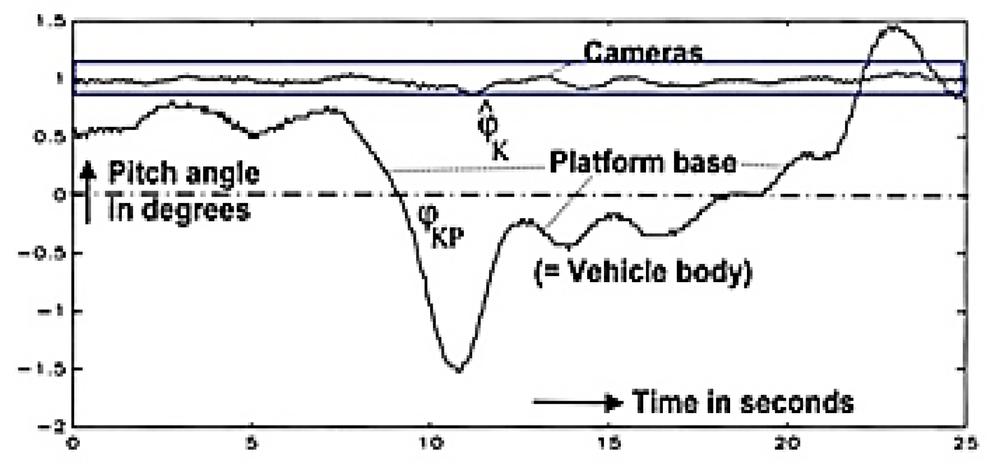
For vehicles experiencing strong angular perturbations like by driving on rough ground, the images will be blurred under poor lighting conditions. Active control of gaze direction allows stabilizing gaze by feedback of rotational rates measured by a set of inexpensive inertial sensors directly on the platform of the eye.
Figure 7 shows experimental results with VaMoRs for a standard braking maneuver. The reduction in amplitude for gaze direction of the cameras (top curve) is more than one order of magnitude relative to the vehicle body (lower curve). Especially for interpreting the images of the high-resolution camera this is an enormous alleviation when tracking a vehicle far away.
2.3. Efficiency Calls for Saccadic Gaze Control
A factor of twelve in resolution in both coordinates of the image leads to an increase in the number of pixels of 144 times that for the high-resolution image (as compared to low resolution). If the high-resolution cameras would be able to simultaneously deliver images of two pyramid stages (each yielding a reduction of one-fourth additional pixels), that is (1 + 1/4 + 1/16) = 1.3125 times 144, this yields 189 times the number of low-resolution pixels in total on three image levels. For a total field of view of 360° x 45° this result in ~212 Giga-pixel per video-cycle. Beside the large number of high-resolution cameras needed for covering a 360° x 45° field of view (about 32 with ~2400 pixel per row and column) the total number of images per video cycle would increase to 52 {32 of 5.76 Giga-pixels plus (8 x 2 = 16) on the first pyramid level (with 1200 x 600 = 0.72 Giga-pixel for medium resolution) and 4 on the second pyramid level (with 600 x 600 = 0,36 Giga-pixel for low resolution)}; so the total number of image points would be (32 x 5.76 + 16 x 0.72 + 4 x 0.36) = 196,96 Giga-pixel, where on the second pyramid level two images in the same azimuth direction have been merged.
With two gaze controllable eyes according to
Figure 5 and Table 1, the number of cameras is reduced to eight (= 25 %), each with much smaller image sizes and only one image per video cycle and camera (a reduction to 15 %). The total number of image points is 2.8 Giga-pixels, corresponding to 1.4 % of the sensor data from the high-resolution cameras mounted fix onto the vehicle body. The factor of about 70 in data volume strongly favors the gaze-controlled vehicle-eye in addition to the reduced locations needed for mounting them all around the vehicle. In [
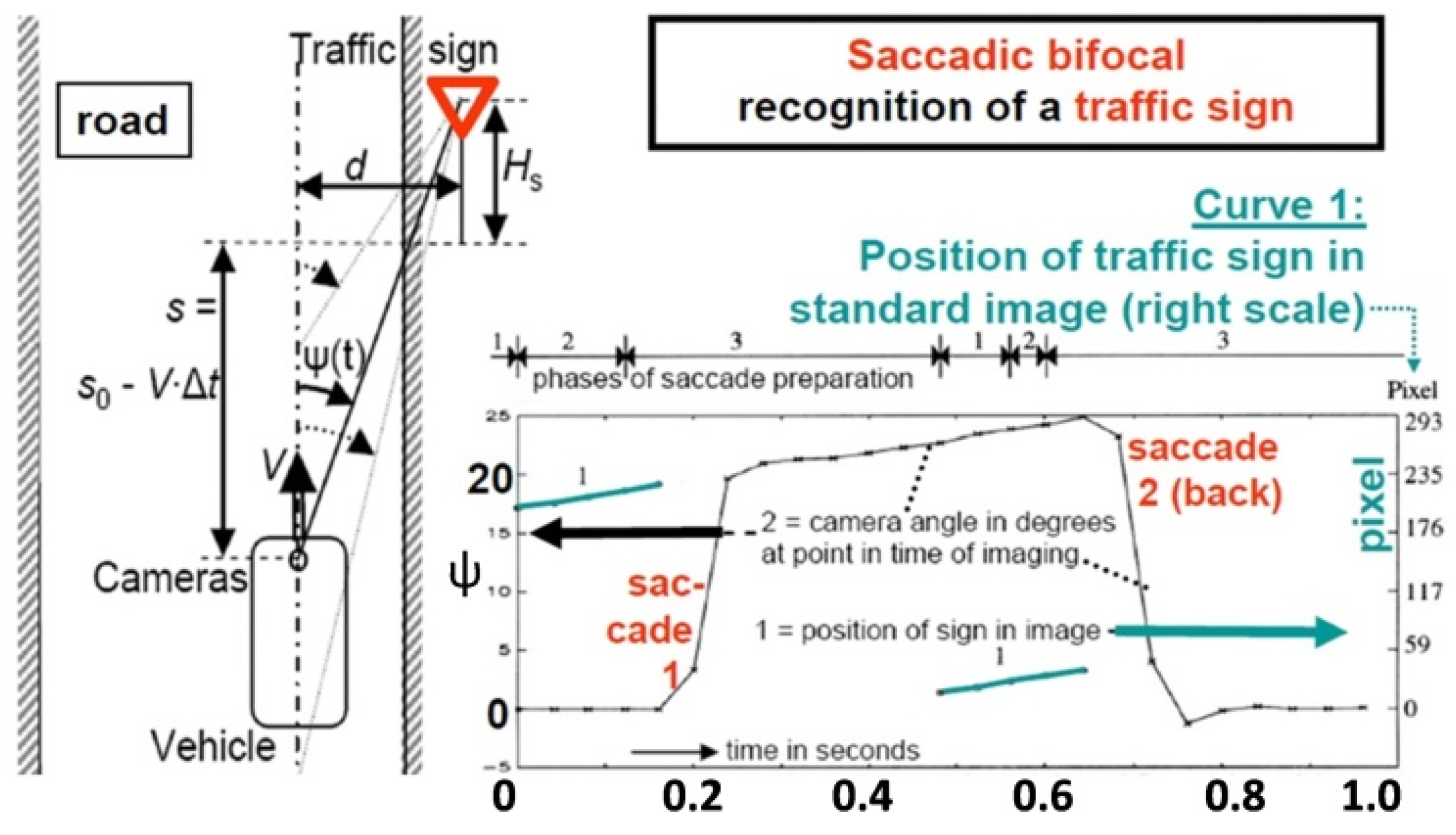
8] the two locations at the top end of the A-frame have been proposed as promising compromise from several points of view. Especially the tracking of traffic signs even up to a close approach in the second or third lane is easily handled. Experience has shown that tracking traffic lights and traffic signs at the side of the road and about 2 m above the ground clearly favors gaze control during approach. Curve 2 in
Figure 8 shows two saccades of about 20° amplitude realized within 0.04 seconds each. Nowadays, the gaze direction could easily be controlled by locking in onto features of the sign, so that the green curve around 0.6 seconds would cover the ψ = 0 line. As can be seen from the video during the saccades, the blurred images of the scene cannot be used; during this short period the vehicle has to live with the dynamical model and the predictions resulting. It takes about eight video cycles (20 to 30 ms) until the images can be interpreted correctly again. This corresponds to the delay time we humans also notice in our biological vision system [
9].
Once gaze control is available in the ‘vehicle eye’ it also allows precise tracking of special objects so that the high-resolution images are easier to interpret. With two independently gaze controllable eyes, two single objects may be tracked and analyzed in parallel.
3. Three Levels of Scene Interpretation
3.1. Structuring the Task Domain on Temporal and Spatial Scales
An experienced human looking at the image in the lower left corner of
Figure 4 cannot but recognize a road scene with at least three lanes; several types of vehicles drive in these lanes (represented in the rounded green square at the center of
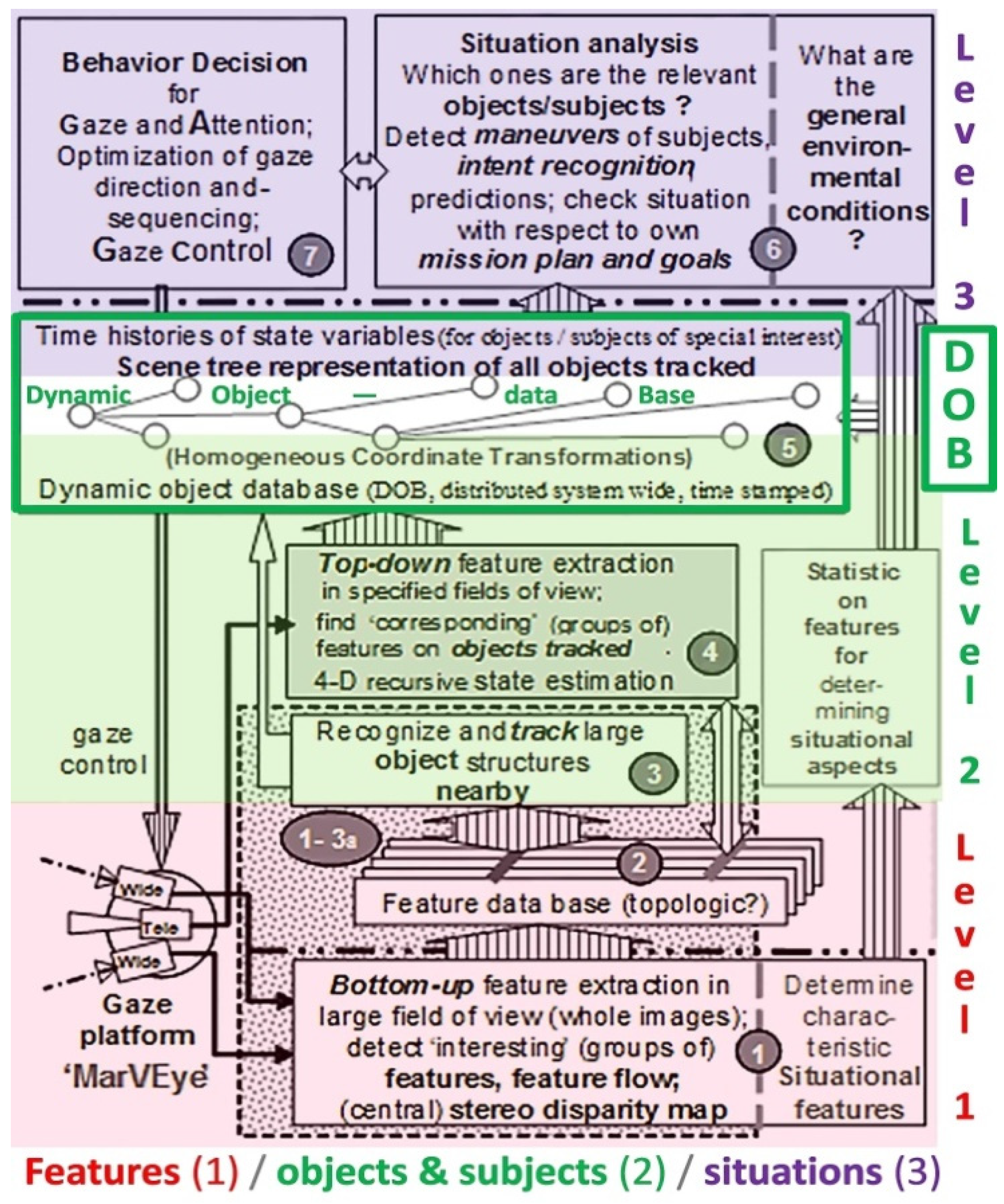
Figure 4). Bottom-up feature extraction and data evaluation ‘here and now’ are done for the entire last image (upper left corner). The results are communicated to the central box in
Figure 4 running at video rate; this central unit tracks the hypotheses for objects and subjects in 3-D space over time. The results are stored in a dynamic object data base (DOB) using a scene tree (see
Figure 9, white field within the green rectangle) as communication device to the situation level-3. On level-2, time is introduced allowing temporally deeper scene understanding with respect to maneuvers and to the overall mission.
Three levels have been implemented for visual cognition and task performance:
Figure 4 and
Figure 9 indicate that an organization of the overall process of performing a mission autonomously should be structured according to three levels:
Image features and other sensor data (bottom-up in each cycle)
Objects (objects proper and subjects as separate classes) in 3-D space and time (4-D), shown in green color.
Mission performance with a special knowledge base on maneuvers: Missions consist of a consecutive list of mission elements which are built by a sequence of maneuvers and their elements (top, magenta).
Level-1 is mainly bottom-up and has to deal with large amounts of sensor data. Levels-2 and -3 may interact every now and then with level-1 with respect to looking for special features derived from knowledge on classes of objects and on mission elements. Level-3 represents the best adaptations of the internal mental imaginations to the external real world by 3-D spatial models of objects and of temporal processes (4-D); this is the knowledge base for perceiving the semantics of the outside world (derived from the sensor data from levels-1 and -2) and for efficient performance of the mission.
The result is a
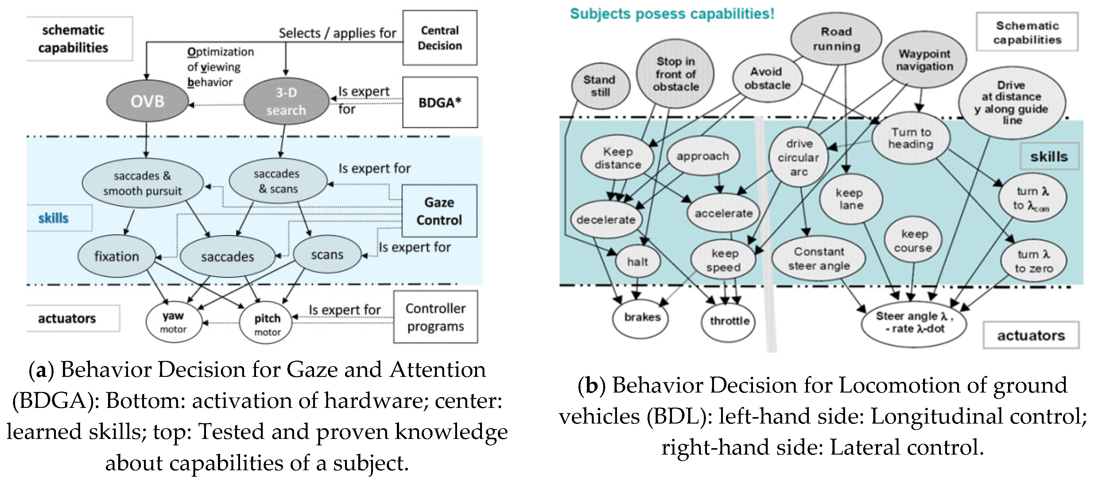
set of capabilities both for perception and for mission performance. Each of these capabilities achieved by a subject is called a skill it has. There are capabilities for behavior decision in gaze and attention (top row in
Figure 10a), which link the mental decisions for gaze control to the actual hardware for realizing them in the subject (bottom row). This shows the capability network for Behavior Decision for Gaze and Attention (BDGA): The group of software that leads to certain skills for realizing the capabilities is marked by a blue background. The arrows indicate which subsystems are involved in realizing the behavior.
Figure 10b shows the capability networks for Behavior Decision in Locomotion of ground vehicles (BDL). Again, the capabilities are shown in the top row, the actuators available for realizing them are seen at the bottom. Before activation of a skill, all subsystems needed are checked whether they are actually available; this is important for autonomous detection of errors that might have occurred in the meantime.
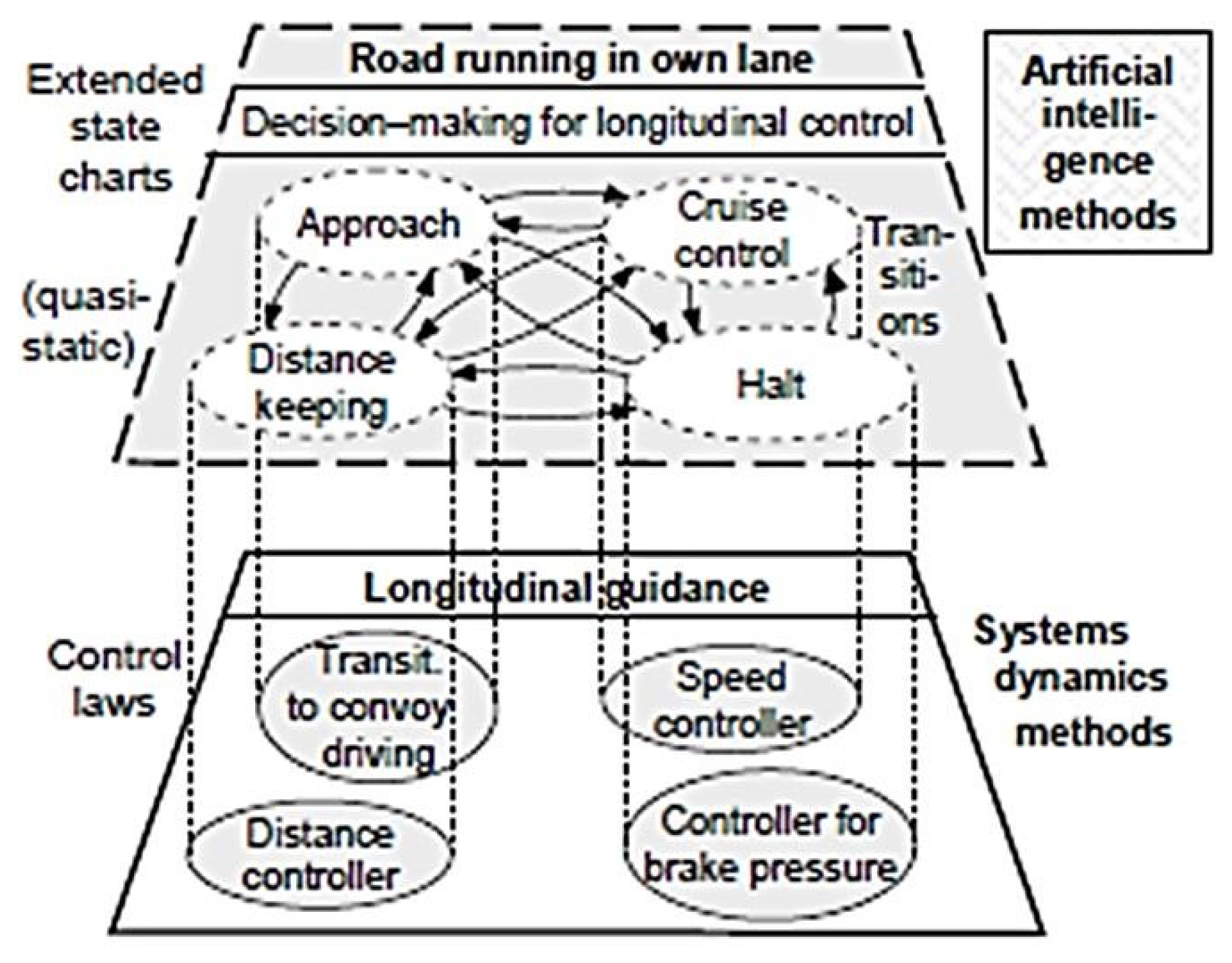
The transition from mental decisions in the main computer system to their realization in the real world with the actuators of the subject is done by a dual representation: 1. with AI-methods on the mental side with extended state charts containing the conditions for transition between the modes [10a) to 10g)], and: 2. with methods from systems dynamics for realization on (embedded, distributed) processors close to the actuators by feed-forward and feedback control laws [10f) and 10g), 11] (see
Figure 11). Details on the realization may be found in [
10] summarizing the results of the AutoNav project till that year, and in [
12,
13,
14,
15].
3.2. Multiple Parallel Feedback Loops in Perception and in Control of Behavior
Many parallel feedback loops result in an overall system for perception of the actual situation and for autonomous execution of a mission.
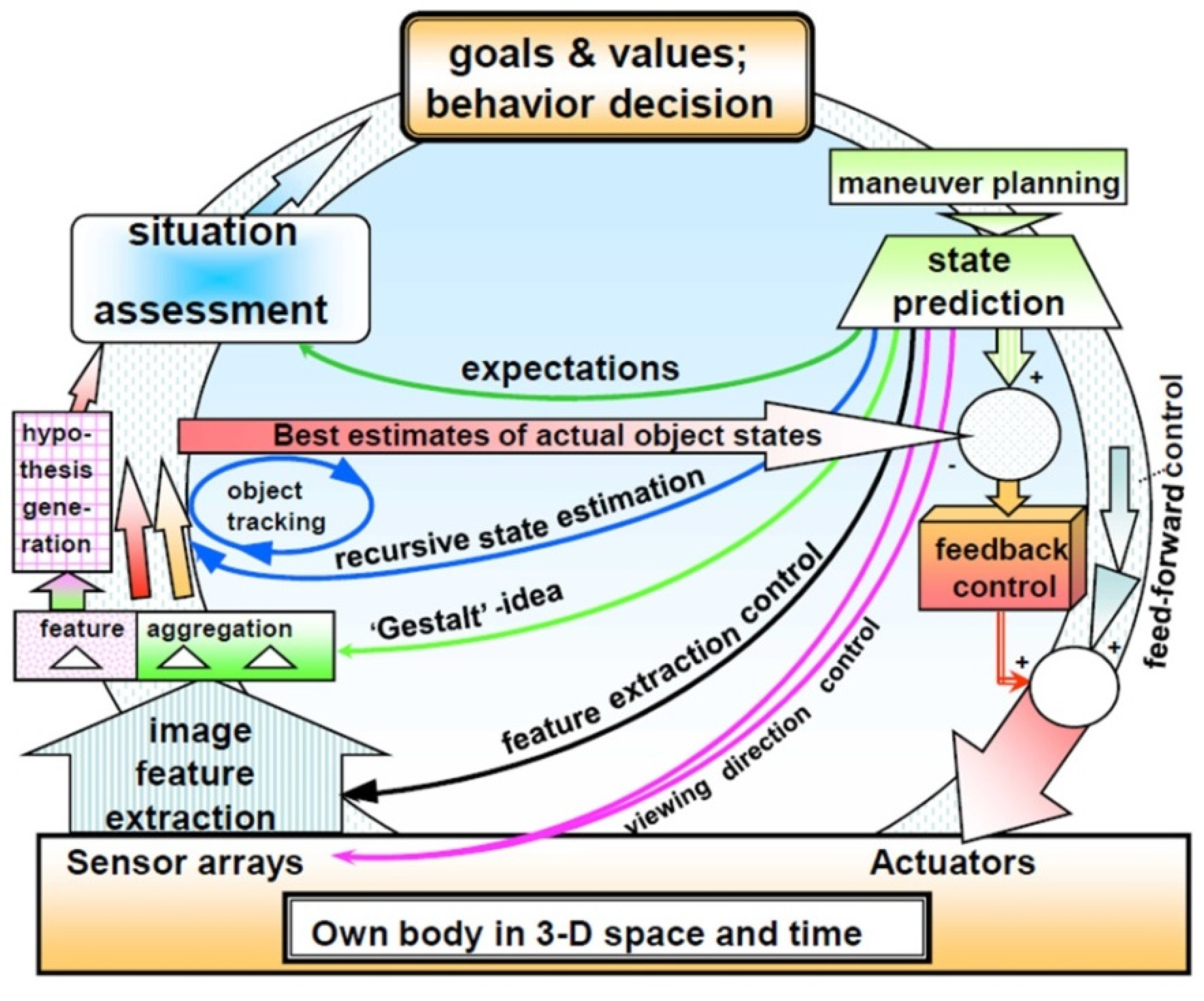
Figure 12 gives a survey on the third-generation system of UniBwM for perception and control of a mission. The mental part encompassing values and goals in decision making has become dominant (see top of the figure). The subject now is no more just part of the material evolution but starts understanding at least part of the processes of evolution observed. Beside its own mental model for the processes observed it has its own values and goals, and in general it will try to move towards an improved state with respect to its individual feelings and its thoughts about the mission. Note that the individual and the cultural value systems of the group may diverge in several points of view, yielding potential conflicts in decision making.
At the bottom of
Figure 12 is the material body of the subject with all its sensors and actuators. State prediction to the next point of evaluation of sensor data and control output is the central activity of the mind (upper right corner of the figure). This triggers both the feed-forward control for maneuvers performed and feedback components for minimizing prediction errors due to unforeseen perturbations from the environment (wide downward-arrow on the right-hand side). From the assessment of the actual situation (in upper left corner) the best direction for visual perception by multi-focal vision is derived and communicated to the corresponding actuators for the control of viewing direction (pink arrow). Another set of feedback loops is included for tracking the features of all objects of interest (black arrow).
The ‘Gestalt’-idea of spatial objects mapped from 3-D to 2-D by perspective projection assists in deriving hypotheses for objects discovered from collections of features in the images (green arrow). For validated hypotheses of objects the blue arrows support efficient tracking of objects over time. The broad horizontal arrow forms the basis for detecting effects of perturbations on the vehicle carrying the sensors. Finally, temporal predictions allow expecting changes in the situation given (dark green arrow). The mental aspects of all these loops have thus become predominant in control of perception and behavior. Note that the knowledge bases for the three levels:
feature extraction and grouping for the step following,
generation of object hypotheses and their tracking over time, and
situation assessment including derivation of control actions for mission performance have to be supported by special interconnected software systems representing the foundation of skills that link the mental world to applications in the real world.
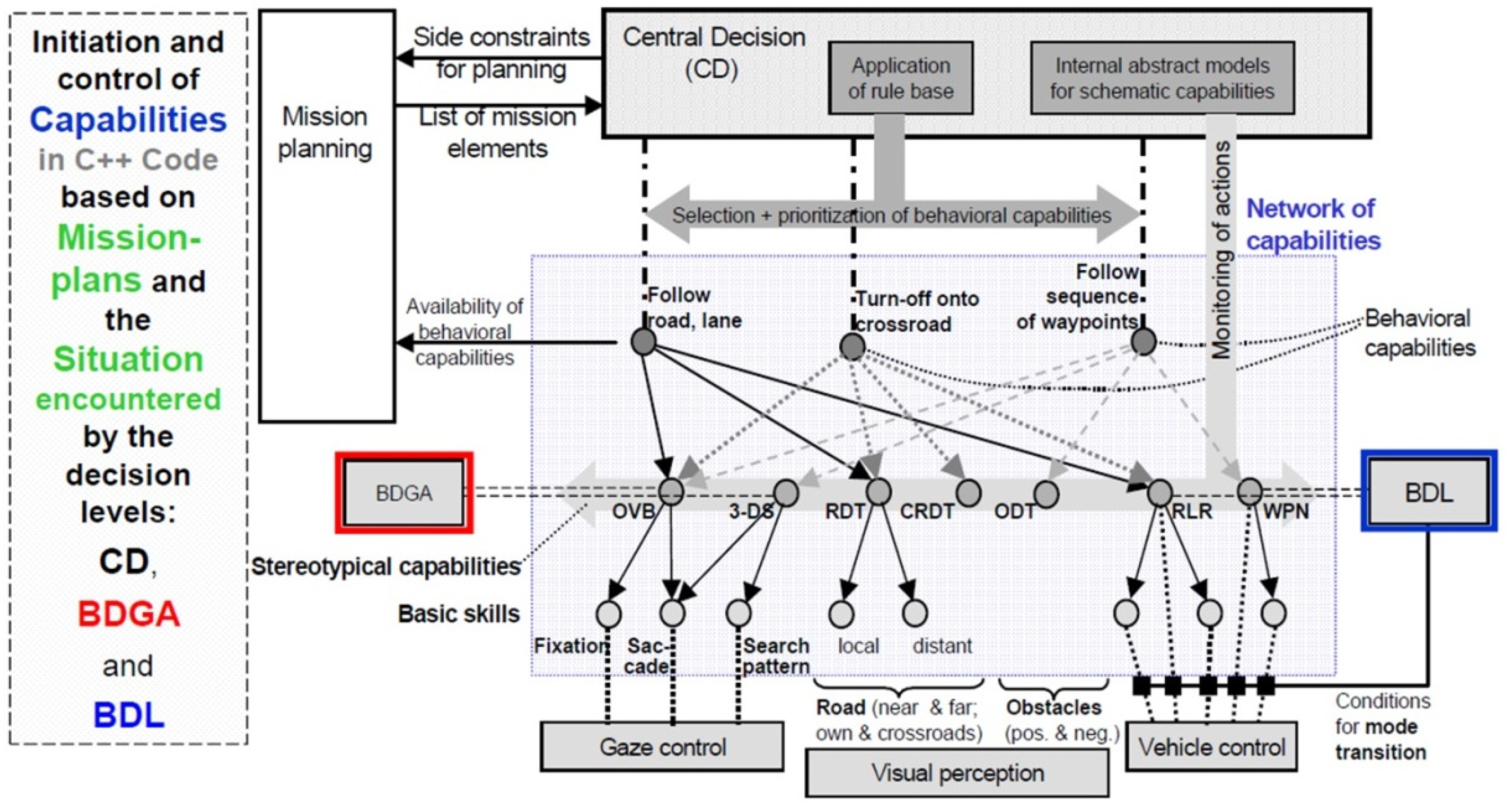
Figure 13 sketches the overall system resulting. The stereotypical capabilities shown on the horizontal connection between BDGA (red rectangle on the left side) and BDL (blue rectangle on the right) in the vertical center of the gray-shaded region now constitute the core of the autonomous system. The upper part shows by the arrows which capabilities are needed for which task (road/lane-following, turning-off onto a crossroad, following a sequence of waypoints). The lower part indicates which basic skills are needed for which capabilities.
The dashed block at the left-hand side in
Figure 13 indicates that the mission to be performed (mission plans, lower right corner in
Figure 4) and the behavioral capabilities actually available have to be provided by the human initiator of the mission. More details may be found in the set of publications at the International Symposium on Intelligent Vehicles [
10] in Dearborn USA. The large rectangle shaded in gray contains all behavioral capabilities available, the stereotypical capabilities to realize them (between BDGA and BDL) in the center, and the skills realized with the subsystems (small circles in lower part). The lower small rectangles group these skills into three behavioral fields: Gaze control (left), visual perception (center), and vehicle control (bottom right). Depending on the sensor systems and the control systems available in the subject, the set of capabilities and skills may be extended to perform other types of missions.
4. What Are the Advantages of EMS-Vision?
The 4-D approach at the core of EMS-vision allows generating by feedback of prediction errors around the point ‘here and now’ some kind of consciousness grounded on the internal knowledge bases and the adaptation of spatiotemporal models available in them. The strict distinction between state- and control variables in these models helps reducing storage requirements for extended maneuvers and missions. Time histories of control variables specify maneuver elements and maneuvers for achieving desired final values of the state variables. Unforeseeable perturbations during per-formance of maneuvers can immediately be counter-acted by feedback of errors between the desired and the actually developing trajectory (see right-hand side of
Figure 12).
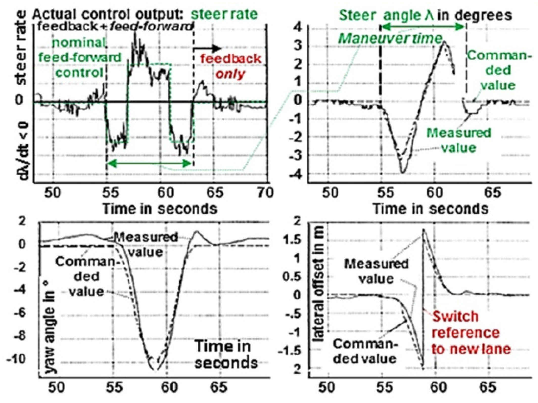
Figure 14 shows a typical result for a lane-change maneuver with the test vehicle VaMP. The green straight lines in the upper left sub-image show the commanded constant steer rates between seconds 55 and 63. It can be seen that the actual steer rates (black curve) deviate quite a bit from the nominal green one. The other sub-images show the corresponding state variables; top right: the steer angle λ; bottom left: the yaw angle of the vehicle, and bottom right: the lateral offset with the switch to the new lane as reference at the center of the maneuver.
With this structure the entire lane change maneuver over ten seconds consists of just five numbers: (1) Time of initiation, (2) magnitude of steer rate for (3) its duration. This results in a linearly changing steer angle and an increasing yaw angle. The immediate (4) opposite pulse from 57 to 59 seconds would lead to a constant yaw angle; however, by directly (5) starting the opposite double impulse in the steer rate (from 59 to 63 seconds with the same maneuver elements) the final yaw angle should be zero again, and the lateral offset just one lane-width if all parameters have been computed correctly. If a feedback component is superimposed after the switch to the new reference lane, the vehicle will always end in the center of the new lane, also for slightly incorrect parameters of the maneuver.
Since beside the state variables in the models for the dynamic behavior of objects observed, also parameters in the structure of these models may be adapted, the overall system will look like shown in the sketch in
Figure 15. Here in parallel to the real world (at left) an internally represented imaginary world is constructed by feedback of prediction errors exploiting spatiotemporal (4-D) models (lower right part, ‘tracking’). Groups of features are assigned to hypothesized objects mapped by the laws of perspective projection. A number of n objects (including subjects) are tracked in parallel (upper left part of the ‘tracking’-circle in the lower right). Unassigned features lead to hypotheses of new objects (‘detection’, center upward) which are tested for a few cycles before a new object is added to the list for tracking. Parameters of the models used may be adapted also for reducing prediction errors (‘learning’ in center top). By storing new successful sets of parameters, the background knowledge is increased from experience (center top). The results of analyzing all observations together with the mission to be performed lead to the control output onto the real vehicle (top loop); these control variables are also fed into the models used for object recognition and their adaptation. This may be a first small step in the direction of a robot mind (see area shaded in gray in
Figure 15).
5. What Would Be a Robot Mind?
In the long run when several subjects observe the same scene by using similar dynamic models, these subjects may exchange their results in order to agree on the models best suited for the actual situation. The availability of a language including common terms for objects, subjects, values and different actions is a prerequisite for developing a robot mind. A robot-subject with a mind should be able to distinguish between itself (the “I”) and the rest of the world (summarized in
Figure 16 within the dash-dotted ellipse). The five words (
I think, therefore I am) printed in large bold letters in
Figure 16 are the once famous statement of Descartes who claimed the mind to be a separate substance; that has become obsolete in the meantime [
16].
Today the mind even is often considered not to be a separate subject but a new quality in the material world that emerged after biological subjects had developed the capabilities of sensing, storing, retrieving and processing of data and knowledge as well as decision making and acting towards certain goals. Mind emerged when these capabilities had reached a higher level of evolution [
17,
18,
19,
20]. In the meantime, also very advanced robotic vehicles may have these capabilities. Will they have a mind?
Humans tend to talk of an object (subject) having a mind if it can make decisions increasing the value of a system observed or of improving its own state. A system realizing all feedback loops in
Figure 12 certainly may be considered having a mind. If goals and values for all potential points in the 4-D matrix of
Figure 4 are essential for decision making, this inarching concept may be called a mind. Of course, there will be many different levels of mind depending on the knowledge bases and the capabilities for both perception and for action of the subject. At present, many of the capabilities for communication and for adaptation of the dynamic models used are with the human operators of the systems; however, there is no reason why this could not be implemented in robotic vehicles also. An exception is the fear sometimes mentioned that these capabilities could make humans superfluous. ─ Another approach to mind generated by technology may be found in [
21] from our American partners in the project AutoNav.
6. Conclusion and Outlook
The 4-D approach to dynamic vision [
22] at the core of EMS-vision allows an immediate realization of the central part of consciousness for a robotic vehicle. It knows where it is relative to the road and what type of objects and other subjects are relative to its own position. Including the capabilities of performing maneuvers based on sequences of simple maneuver elements and of counteracting perturbations experienced by feedback of prediction errors makes the method very efficient also for environments hard to predict correctly.
It is interesting to note that feedback of prediction errors has become a topic in cognition lately in the fields of psychology and philosophy [
23,
24,
25,
26,
27]. It would be interesting to check whether EMS-vision combined with neural net methods could merge the positive aspects of both approaches.
References
- Meissner A. Steuerung dynamischer Systeme aufgrund bildhafter Informationen. PhD-thesis UniBwM, LRT, 1982.
- IV’94 Five papers in: Masaki (ed): Proc. of Int. Symp. on Intelligent Vehicles ‘94, Paris, Oct. 1994:.
- Dickmanns E.D.; Behringer R.; Dickmanns D.; Hildebrandt T.; Maurer M.; Thomanek F.; Schiehlen J. The Seeing Passenger Car ‘VaMoRs-P’, pp 68-73. [CrossRef]
- Schiehlen J.; Dickmanns E.D.: A Camera Platform for Intelligent Vehicles. pp 393-398. [CrossRef]
- Thomanek F.; Dickmanns ED; Dickmanns D. Multiple Object Recognition and Scene Interpretation for Autonomous Road Vehicle Guidance. pp 231-236. [CrossRef]
- von Holt V. Tracking and Classification of Overtaking Vehicles on Autobahnen, pp 314-319. [CrossRef]
- Behringer R. Road recognition from Multifocal Vision. [CrossRef]
- Thomanek F. Visuelle Erkennung und Zustandsschätzung von mehreren Straßenfahrzeugen zur autonomen Fahrzeugführung. PhD-thesis UniBwM, LRT, 1996.
- Behringer R. Visuelle Erkennung und Interpretation des Fahrspurverlaufes durch Rechnersehen für ein autonomes Straßenfahrzeug. PhD-thesis UniBwM, LRT, 1996.
- Dickmanns E.D. Dynamic Vision for Perception and Control of Motion. Springer-Verlag, April 2007, (474 pages, sect. 9.4.2). [CrossRef]
- Hubel D.H.; Wiesel T. Receptive fields, binocular interaction, and functional architecture in the cat’s visual cortex. Journal of Physiology, 160: 1962, pp 106-154,. [CrossRef]
- Dickmanns E.D.; Wuensche H.-J. Nonplanarity and efficient multiple feature extraction. Proc. Int. Conf. on Vision and Applications (Visapp), Setubal, Febr. 2006.
- Dickmanns E.D. May a pair of ‘Eyes’ be optimal for vehicles too? Electronics 2020, 9(5), 759; (This article belongs to the Special Issue ‘Autonomous Vehicles Technology’). [CrossRef]
- Pöppel E.; Chen L.; Glünder H.; Mitzdorf U.; Ruhnau E.; Schill K.; von Steinbüchel N. Temporal and spatial constraints for mental modelling. In: Bhatkar, Rege K (eds): Frontiers in knowledge-based computing, Narosa, New Dehli, 1991, pp 57–69.
- Proceedings of Symposium on ‘Intelligent Vehicles’00’ (IV‘2000). Dearborn, MI, USA, Oct. 2000, with the following contributions on EMS-Vision:.
- Gregor R.; Lützeler M.; Pellkofer M.; Siedersberger K.H.; Dickmanns E. D. EMS-Vision: A Perceptual System for Autonomous Vehicles. pp. 52 – 57. [CrossRef]
- Gregor R.; Dickmanns E.D. EMS-Vision: Mission Performance on Road Networks. pp. 140 – 145. [CrossRef]
- Hofmann U.; Rieder A.; Dickmanns E.D. EMS-Vision: An Application to Intelligent Cruise Control for High Speed Roads. pp. 468 – 473. [CrossRef]
- Lützeler M.; Dickmanns E.D. EMS-Vision: Recognition of Intersections on Unmarked Road Networks. pp 302 – 307. [CrossRef]
- Maurer: M. Knowledge Representation for Flexible Automation of Land Vehicles. pp. 575 – 580. [CrossRef]
- Pellkofer M.; Dickmanns E.D. EMS-Vision: Gaze Control in Autonomous Vehicles. pp. 296 – 301. [CrossRef]
- Siedersberger K-H.; Dickmanns E.D. EMS-Vision: Enhanced Abilities for Locomotion. pp. 146-151.
- Siedersberger K-H. Komponenten zur automatischen Fahrzeugführung in sehenden (semi-) autonomen Fahrzeugen. PhD-thesis UniBwM, LRT, 2004.
- Pellkofer M.; Lützeler M.; Dickmanns E.D. Interaction of Perception and Gaze Control in Autonomous Vehicles. Proc. SPIE: Intelligent Robots and Computer Vision XX; Oct. 2001, Newton, USA, pp 1-12.
- Siedersberger K.-H.; Pellkofer M.; Lützeler M.; Dickmanns E.D.; Rieder A.; Mandelbaum R.; Bogoni I. Combining EMS-Vision and Horopter Stereo for Obstacle Avoidance of Autonomous Vehicles. Proc. ICVS, Vancouver, July 2001. [CrossRef]
- Pellkofer M.; Dickmanns E.D. Behavior Decision in Autonomous Vehicles. Proc. of the Int. Symp. on ‚Intell. Veh.‘02‘, Versailles, June 2003.
- Gregor R.; Lützeler M.; Pellkofer M.; Siedersberger K.H.; Dickmanns E.D. EMS-Vision: A Perceptual System for Autonomous Vehicles. IEEE Trans. on Intelligent Transportation Systems, Vol.3, No.1, March 2002, pp. 48-59. [CrossRef]
- Damasio AR. Descartes’ Irrtum. Fühlen, Denken und das menschliche Gehirn. Paul List Verlag 1995 (384 Seiten).
- von Holst E.; Mittelstaedt M. Das Reafferenzprinzip. Naturwissenschaften. Vol. 37,1950, pp 464-476.
- Singer W. Neurobiology of Human Values. Springer, 2005, ISBN 978-3-540-26253-4. [CrossRef]
- Singer W. Dynamic coordination in the brain: from neurons to mind. MIT Press, 2010, ISBN 978-3-642-11667-4.
- von Heiseler T. N. Language evolved for storytelling in a super-fast evolution. In: R. L. C. Cartmill, Hrsg. Evolution of Language. London: World Scientific,2014 pp. 114-121.
- Albus J. S.; Meystel A. M. Engineering of Mind. – An introduction to the science of intelligent systems. J. Wiley & Sons Publication, New York, 2001, 411 pages.
- Dickmanns E.D.; Graefe V.: a) Dynamic monocular machine vision. Machine Vision and Appl., Springer International, Vol. 1, 1988, pp 223-240. b) Applications of dynamic monocular machine vision. (ibid), pp. 241-261. [CrossRef]
- Friston K. The free-energy princip. In T. K. Metzinger & J. M. Windt (Eds.) Open MIND. 2010. [CrossRef]
- Menary R. Cognitive integration, enculturated cognition and the socially extended mind. Cognitive Systems Research, 2013, pp 25-26, 26–34. [CrossRef]
- Hohwy J. The predictive mind. Oxford: Oxford University Press. 2013. [CrossRef]
- Hohwy J. The self-evidencing brain. Noûs, 50 (2), 259–285. 2016. [CrossRef]
- Fabry R. E. Predictive processing and cognitive development. In T. Metzinger & W. Wiese (Eds.) Philosophy and predictive processing. le: A unified brain theory? Nature Reviews Neuroscience, 11(2), 2017, 127–138. [CrossRef]
Figure 1.
Test vehicle 5-t van VaMoRs 1986.
Figure 1.
Test vehicle 5-t van VaMoRs 1986.
Figure 2.
VaMP 1994: (top left) components for autonomous driving; (right) VaMP and view into the passenger cabin (bottom); (lower left) bifocal camera arrangement (front) on a yaw platform.
Figure 2.
VaMP 1994: (top left) components for autonomous driving; (right) VaMP and view into the passenger cabin (bottom); (lower left) bifocal camera arrangement (front) on a yaw platform.
Figure 3.
Second-generation vision system with up to 60 ‘transputers’: Real-time processing of four video-fields (top left) according to the 4-D approach on three levels: The Dynamic Object data Base (DOB in green) reduces the data volume on the feature level for the upper level (Situation Assessment and Behavior Decision and control) by two to three orders of magnitude without loss of essential information.
Figure 4.
Spatial (vertical) and temporal (horizontal) structuring of the 4-D action space for multiple parallel visual / inertial perception.
Figure 4.
Spatial (vertical) and temporal (horizontal) structuring of the 4-D action space for multiple parallel visual / inertial perception.
Figure 5.
‘Vehicle-eye’ with three different focal lengths and two wide-angle cameras with diver-gent gaze direction [
8].
Figure 5.
‘Vehicle-eye’ with three different focal lengths and two wide-angle cameras with diver-gent gaze direction [
8].
Figure 6.
Camera set used in VaMoRs in the AutoNav-project 1997 – 2003.
Figure 6.
Camera set used in VaMoRs in the AutoNav-project 1997 – 2003.
Figure 7.
Gaze stabilization during a braking maneuver of VaMoRs.
Figure 7.
Gaze stabilization during a braking maneuver of VaMoRs.
Figure 8.
Detection and tracking of a traffic sign by saccadic vision 1994 with VaMoRs. During approach both pan and tilt angles may become rather large. Curve 2 shows the gaze angle in degrees relative to the vehicle. (see video “GazeControlTraffic-SignSaccade1994“).
Figure 8.
Detection and tracking of a traffic sign by saccadic vision 1994 with VaMoRs. During approach both pan and tilt angles may become rather large. Curve 2 shows the gaze angle in degrees relative to the vehicle. (see video “GazeControlTraffic-SignSaccade1994“).
Figure 9.
Three levels for dynamic scene understanding in the 4-D approach.
Figure 9.
Three levels for dynamic scene understanding in the 4-D approach.
Figure 10.
Capabilities as flexible concept for linking the mental world to real-world hardware for performing maneuvers and missions.
Figure 10.
Capabilities as flexible concept for linking the mental world to real-world hardware for performing maneuvers and missions.
Figure 11.
Dual representation of behavioral modes with methods from Artificial Intelligence (top, dashed) and systems dynamics (bottom).
Figure 11.
Dual representation of behavioral modes with methods from Artificial Intelligence (top, dashed) and systems dynamics (bottom).
Figure 12.
Multiple feedback loops of the 4-D approach for autonomous performance of a mission.
Figure 12.
Multiple feedback loops of the 4-D approach for autonomous performance of a mission.
Figure 13.
Behavior Decision for Gaze and Attention (BDGA in red) and for Locomotion (BDL in blue); abbreviations: OVB = Optimization of Viewing Behavior, 3-DS = 3-D Search, RDT = Road Detection and Tracking, CRDT = Cross Road Detection and Tracking, ODT = Object Detection and Tracking, RLR = Road and Lane Recognition, WPN = Way-Point Navigation.
Figure 14.
Maneuvers as Knowledge Elements for Vision and Control: Lane change with VaMP.
Figure 14.
Maneuvers as Knowledge Elements for Vision and Control: Lane change with VaMP.
Figure 15.
Generation of a mental world in parallel to the real outside world (rectangle at left) based on measurement values and the 4-D approach by feedback of prediction errors ‘here and now’.
Figure 15.
Generation of a mental world in parallel to the real outside world (rectangle at left) based on measurement values and the 4-D approach by feedback of prediction errors ‘here and now’.
Figure 16.
Visualization of closed loops needed between several subjects for the development of a common mind.
Figure 16.
Visualization of closed loops needed between several subjects for the development of a common mind.
|
Disclaimer/Publisher’s Note: The statements, opinions and data contained in all publications are solely those of the individual author(s) and contributor(s) and not of MDPI and/or the editor(s). MDPI and/or the editor(s) disclaim responsibility for any injury to people or property resulting from any ideas, methods, instructions or products referred to in the content. |
© 2024 by the authors. Licensee MDPI, Basel, Switzerland. This article is an open access article distributed under the terms and conditions of the Creative Commons Attribution (CC BY) license (http://creativecommons.org/licenses/by/4.0/).
