Submitted:
31 May 2024
Posted:
01 June 2024
You are already at the latest version
Abstract
Keywords:
1. Introduction
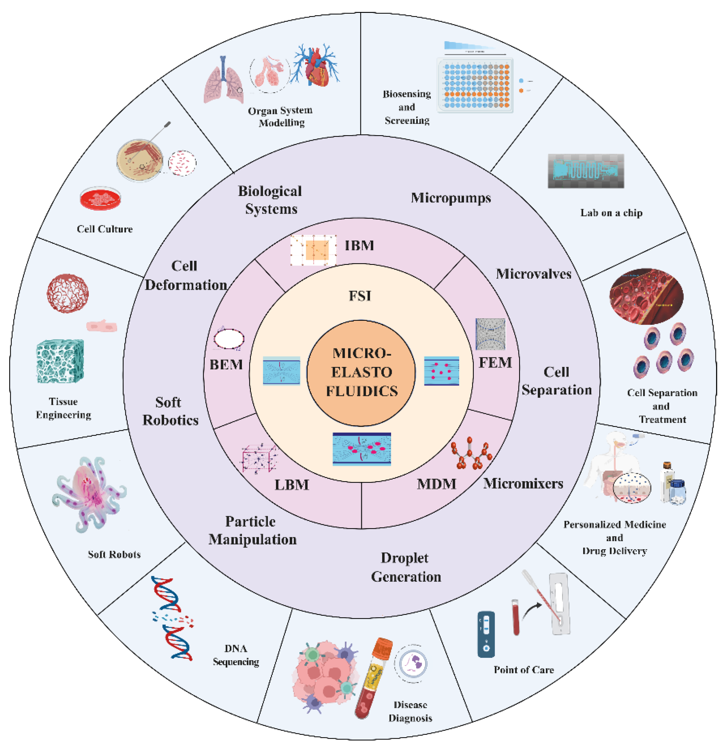
2. Fundamentals of Fluid-Structure Interaction in Micro Elastofluidics
2.1. Fundamentals of Fluid-Structure Interaction
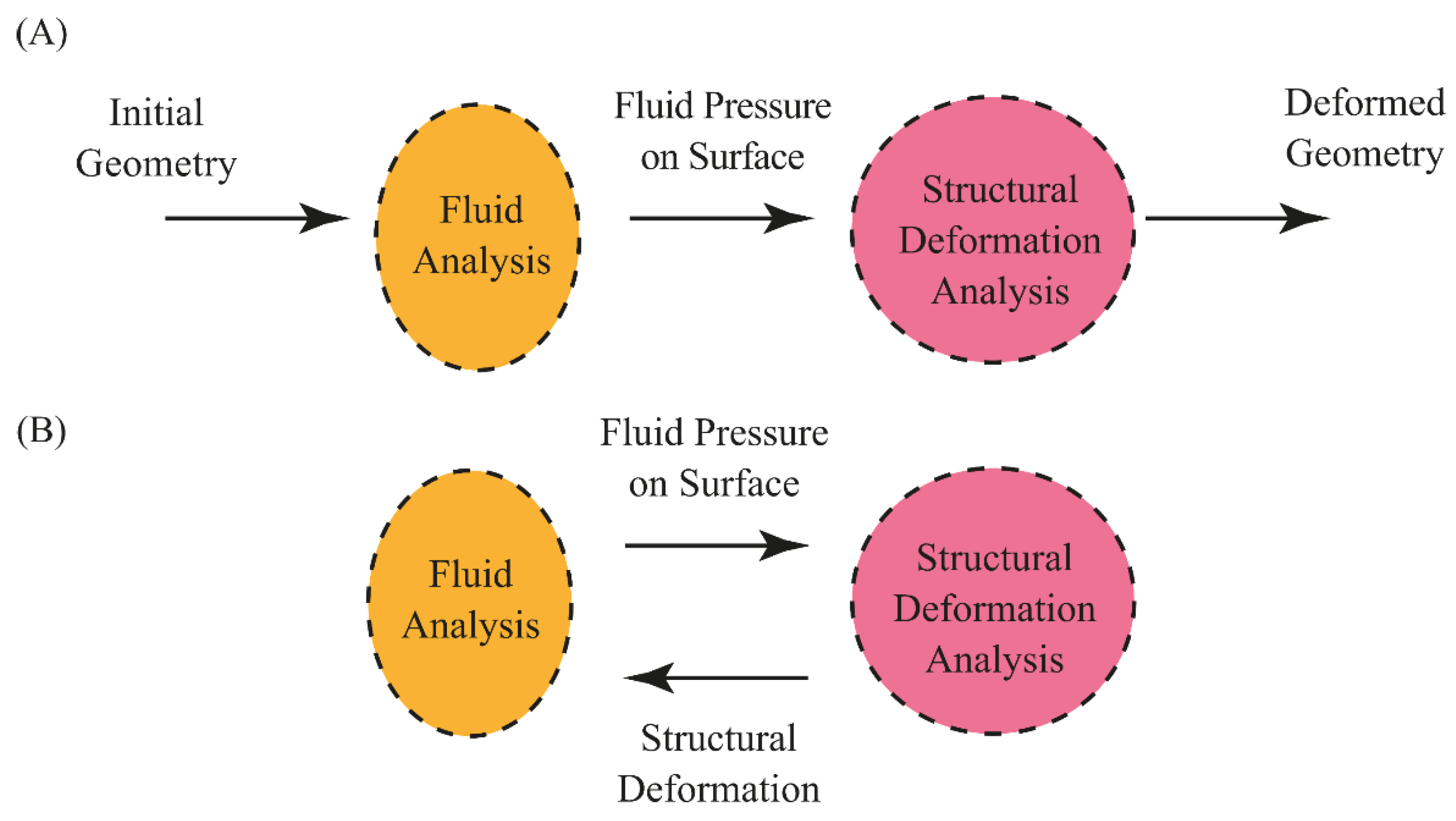

2.2. Fluid Dynamics and Solid Mechanics of FSI
2.3. Boundary Conditions
2.4. Coupling Approaches
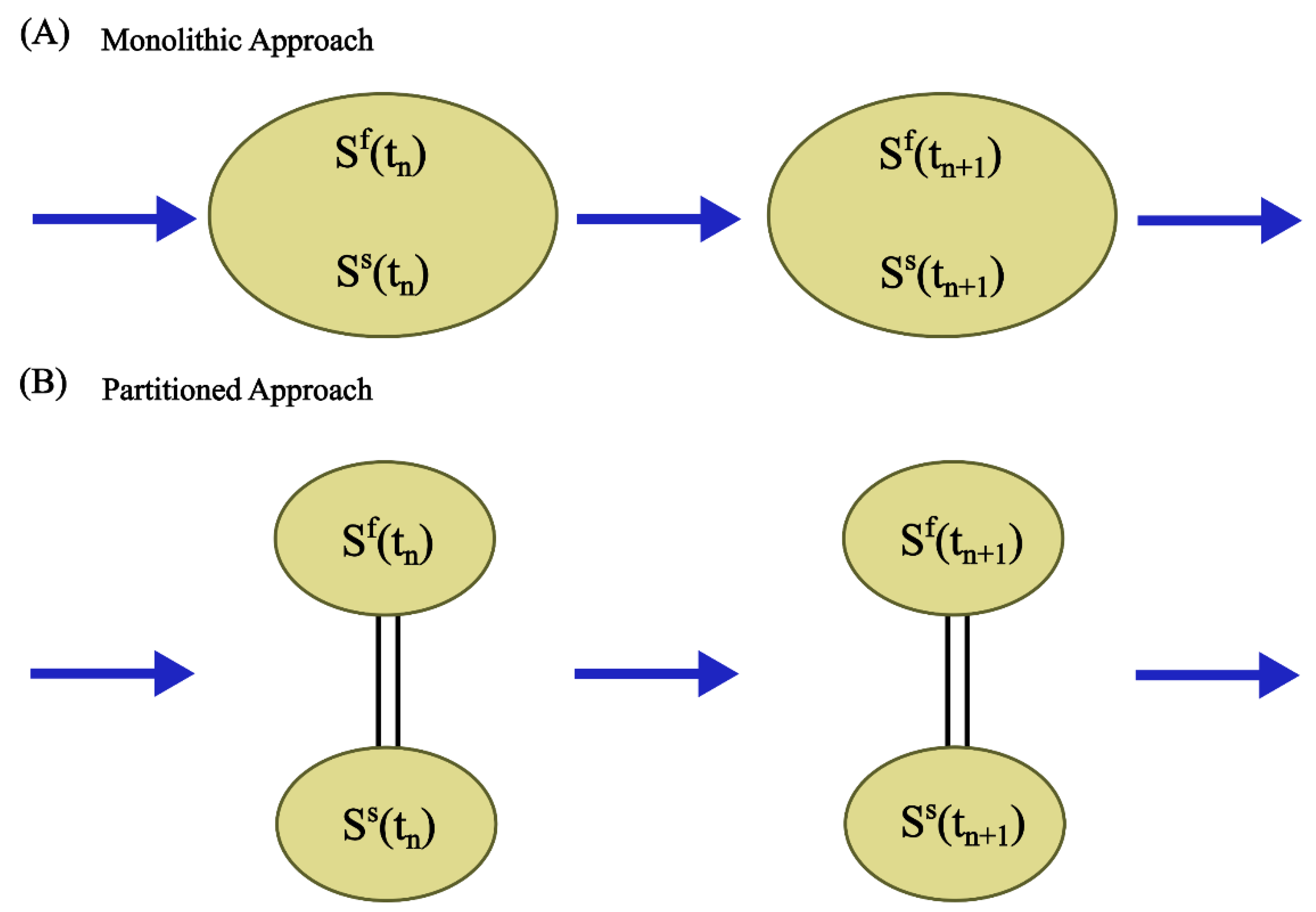
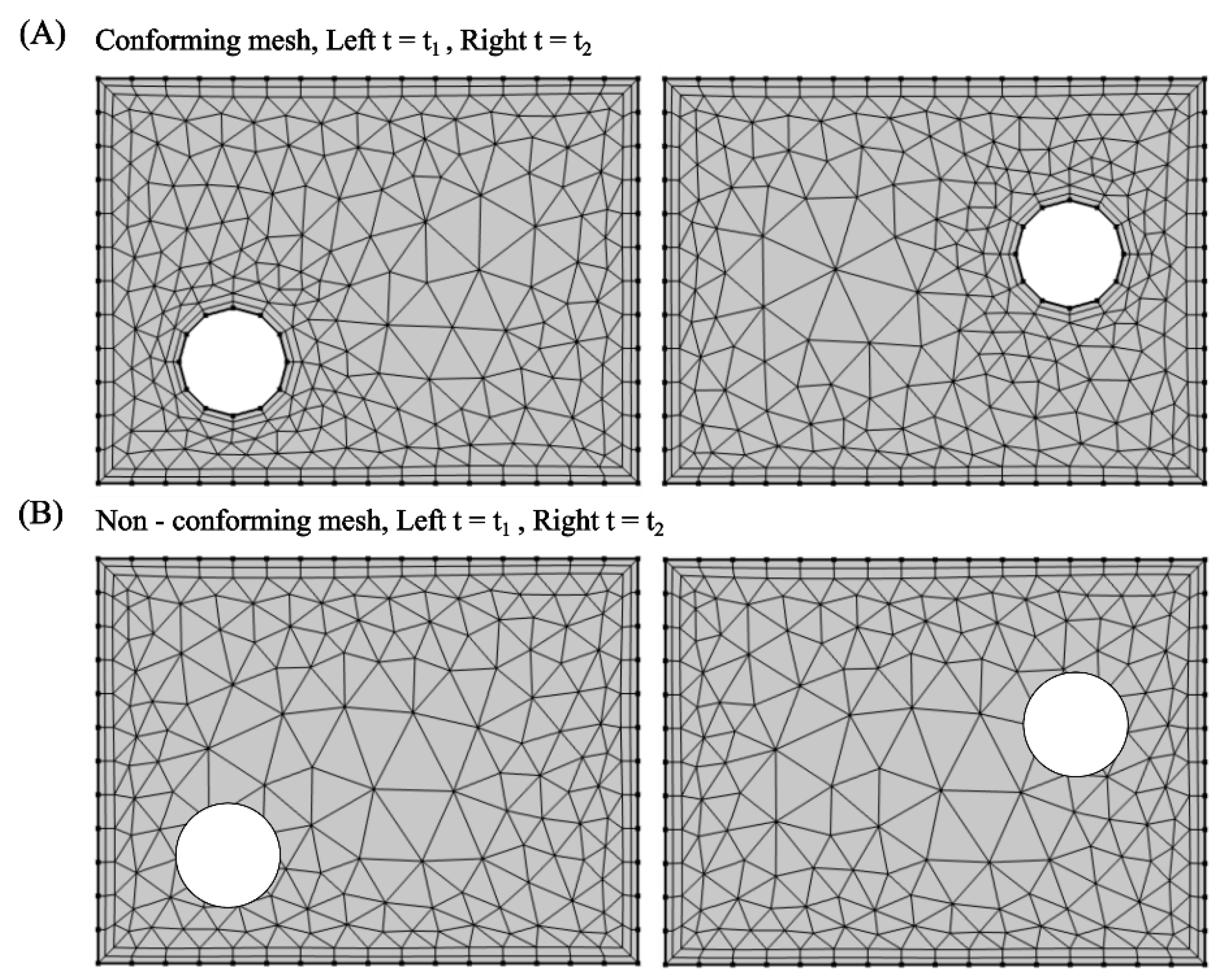
3. Computational Methods for Studying Fluid-Structure Interactions
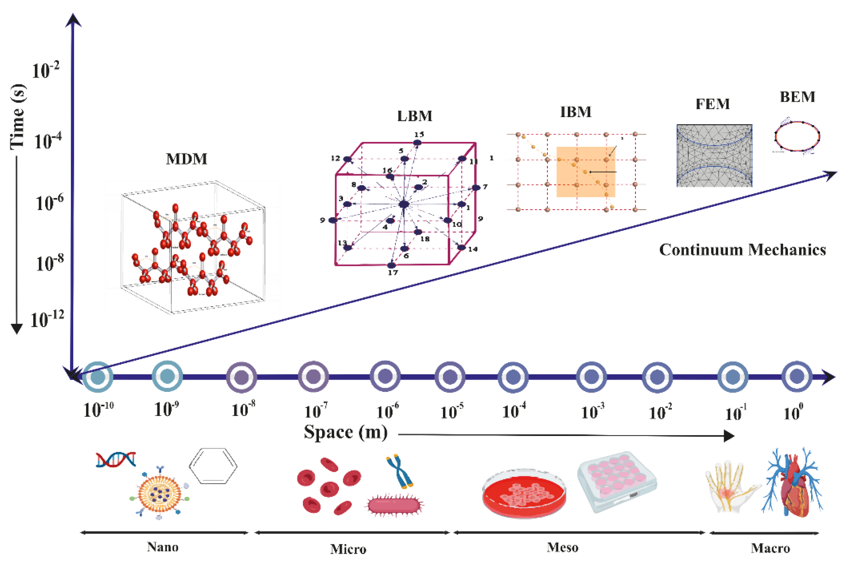
3.1. Finite Element Method
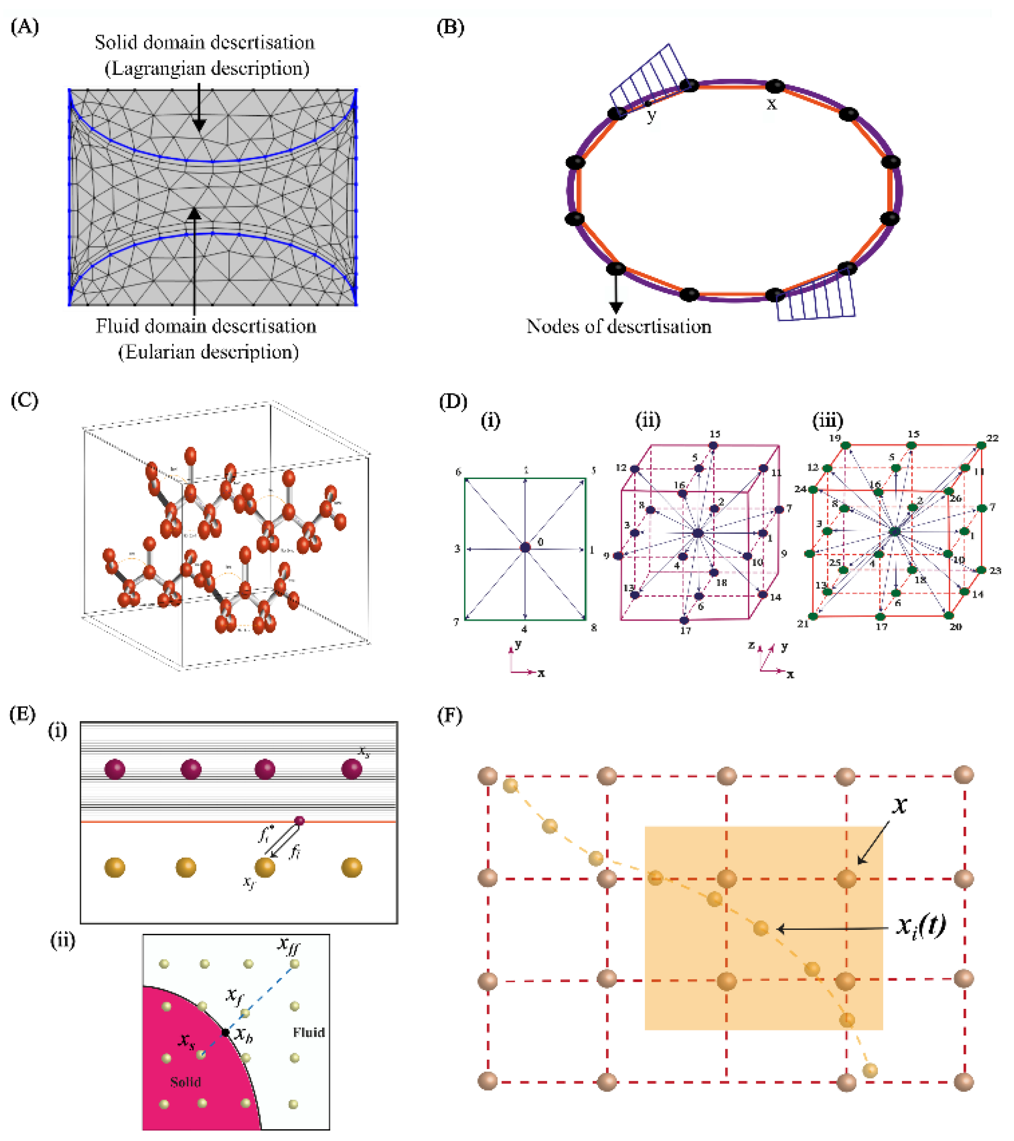
3.1.1. Modelling of Fluid Domain
3.1.2. Modelling of Deformable Structure
3.2. Boundary Element Method
3.3. Molecular Dynamics Method
3.4. Lattice Boltzmann Method
3.4.1. Force Application in FSI
3.4.2. Boundary Conditions
3.5. Immersed Body Method in FSI
| Feature | FEM |
BEM |
MD | LBM | IBM | ||
|
Basic Principle |
Divides problem domain into discrete elements. Solves for field variables. | Reduces dimensionality by focusing on boundaries only. Solves integral equations. | Simulates behaviour of atoms and molecules using Newton's laws of motion. | Simulates fluid dynamics using discrete particle distribution functions on a lattice. | Simulates fluid and structure interaction by embedding the structure in a fluid mesh. | ||
| Primary Applications | Structural analysis, micropumps and microvalves. | Acoustic streaming in microfluidics, fluid flow in infinite domains | Biophysics, chemistry, biosensors, and drug delivery systems. | Droplet Generation, fluid flow in complex geometries, multiphase and multicomponent flows | Complex fluid-structure interactions, cardiovascular simulations, biological flows. | ||
| Computational Domain | Volumetric domain requires discretization of the entire region. | Surface-based, requires discretization of the boundary only. | Atomic or molecular scale simulates each particle individually. | Volumetric, based on a fixed grid of discrete points. | Hybrid approach combines a fluid mesh with structures that do not conform to the mesh. | ||
| Strengths | Flexible, can handle complex geometries and multiphysics problems. | Less discretization is needed, faster for problems with small boundaries. | Provides detailed molecular-level information. | Efficient for complex boundary conditions and scalable for large systems. | Efficiently handles interaction between fluid and immersed structures without requiring mesh conformity. | ||
| Weaknesses | Can be computationally intensive, especially for large or complex domains. | Limited to problems where boundary definition is clear and sufficient. | Computationally intensive, limited to relatively small system sizes or short time scales. | Accuracy depends on lattice resolution, and handling complex physics can be challenging. | Can suffer from accuracy issues near the boundary between the fluid and the structure. | ||
| Mesh Dependency | Highly mesh-dependent, solution accuracy increases with finer mesh. | Only boundary needs meshing, reducing overall mesh dependency. | No traditional mesh, but particle density and interaction range are crucial. | Mesh (lattice) dependent, though generally less sensitive than FEM. | Mesh of the fluid needs to be fine enough to accurately capture boundary layer phenomena. | ||
| Typical Solvers | Direct solvers, iterative solvers. | Boundary integral methods, direct solvers. | Verlet integration, velocity Verlet, leapfrog methods. | Collision and streaming operators, often using BGK approximation. | Direct forcing methods, Lagrangian-Eulerian solvers. | ||
| Software Examples | ANSYS, Abaqus, COMSOL Multiphysics. | ANSYS, BEASY, Altair AcuSolve. | LAMMPS, GROMACS, NAMD. | Palabos, OpenLB, LBMflow.). | IBAMR, immersed boundary (MATLAB) | ||
4. Applications
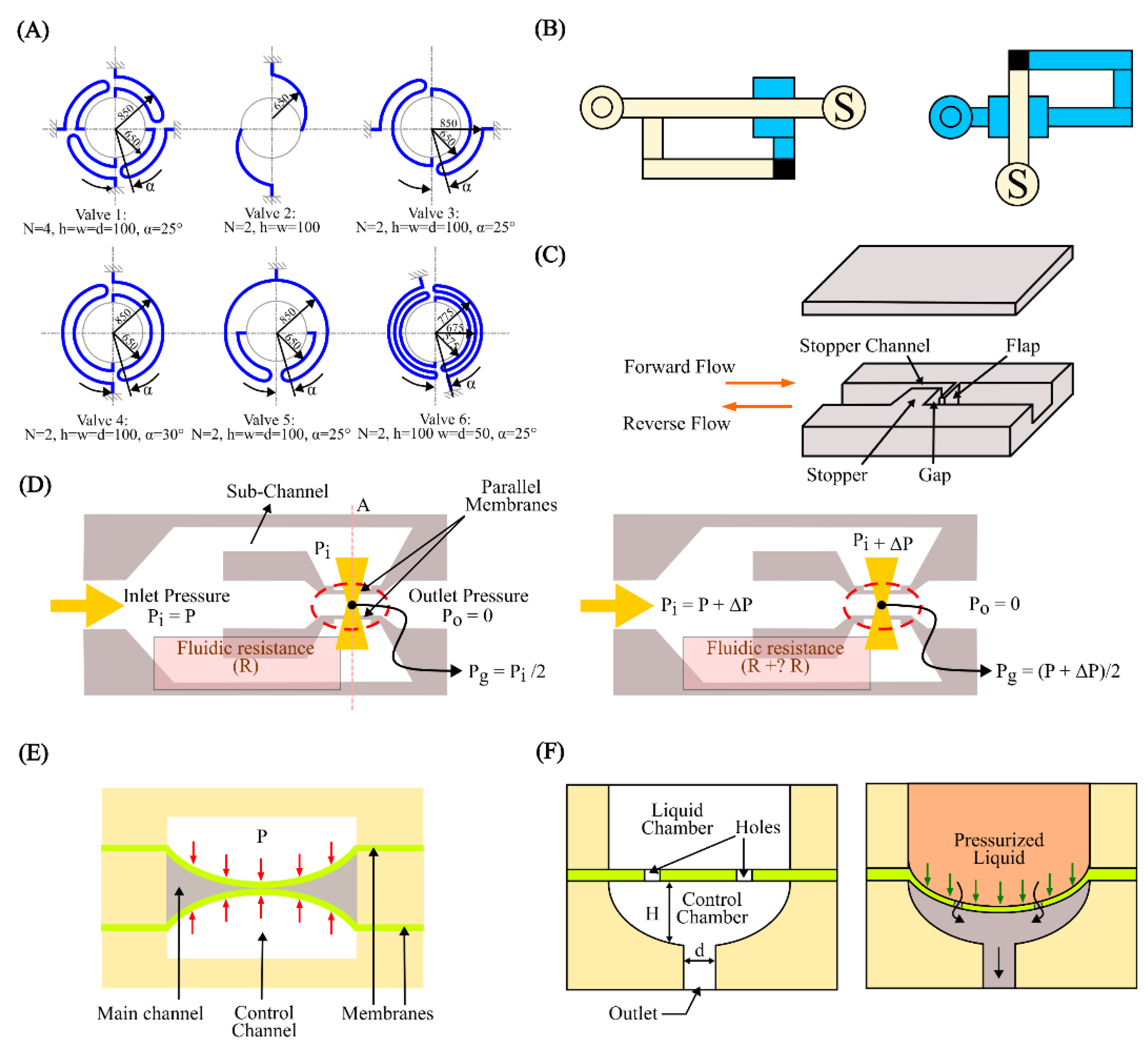
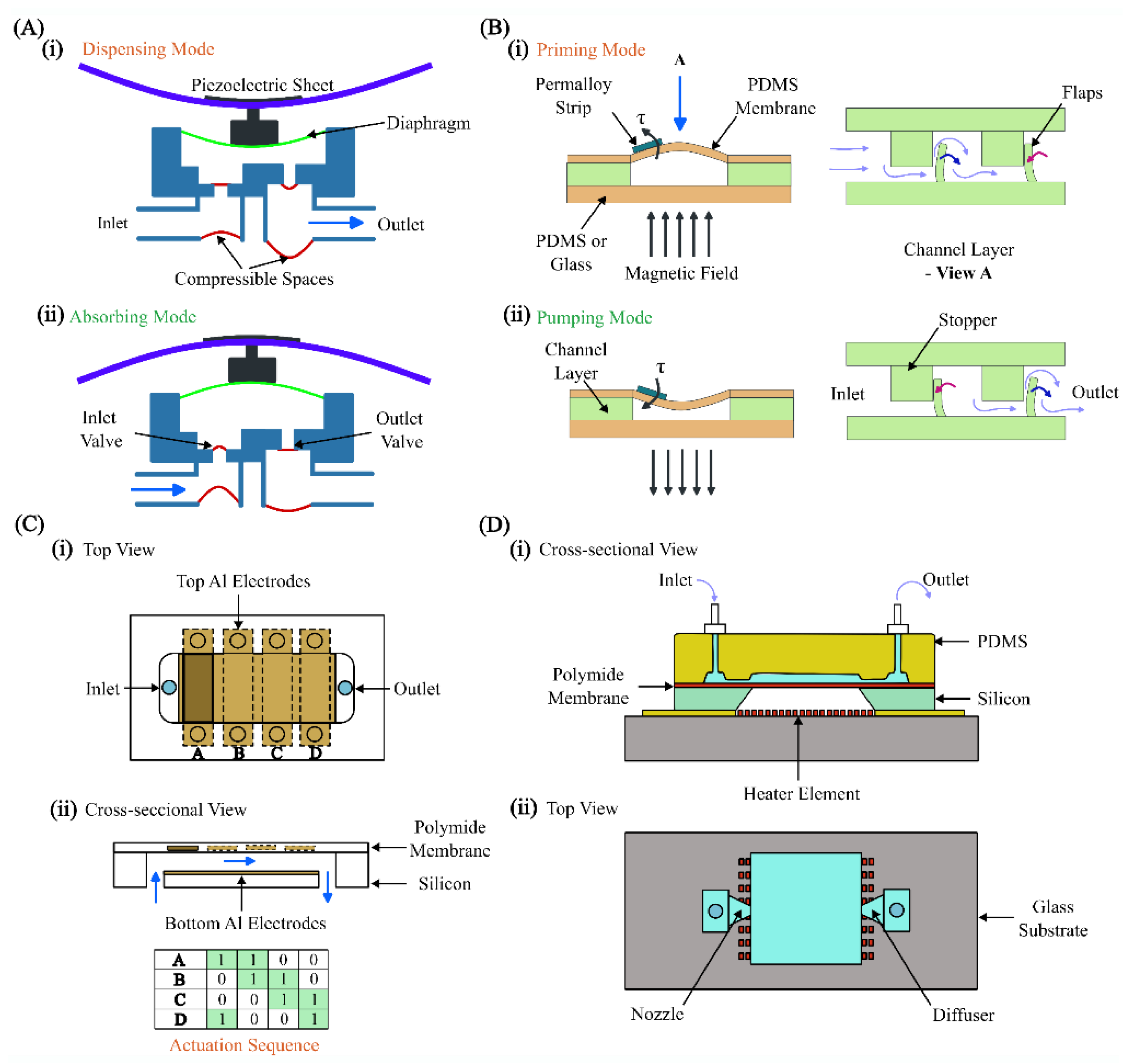
4.1. Microvalves and Micropumps
4.2. Cell and Particle Manipulation
4.3. Micromixers
4.4. Modelling Cardiovascular Systems
5. Discussion and Future Perspectives
Author Contributions
Conflicts of Interests
Acknowledgments
Abbreviations
| 2D | Two-dimensional |
| 3D | Three-dimensional |
| AI | Artificial Intelligence |
| ATAA | Ascending Thoracic Aortic Aneurysm |
| BEM | Boundary Element Method |
| BGK | Bhathagar–Gross–Krook |
| CFD | Computational Fluid Dynamics |
| CS-FEM | Cell-based Smoothed Finite Element Method |
| CSM | Computational Structural Mechanics |
| CT | Computed Tomography |
| CTCs | Circulating Tumor Cells |
| DLD | Deterministic Lateral Displacement |
| EM | Electromagnetic |
| FEM | Finite Element Method |
| FSI | Fluid-Structure Interaction |
| IBM | Immersed Boundary Method |
| IPMF | Inertial Particle Microfluidics |
| LBE | Lattice Boltzmann Equation |
| LBGK | Lattice Bhathagar–Gross–Krook |
| LBM | Lattice Boltzmann Method |
| LSM | Lattice Spring Model |
| MD | Molecular Dynamics |
| MEMS | Micro-electromechanical Systems |
| PDEs | Partial Differential Equations |
| PDMS | Polydimethylsiloxane |
| PMMA | Polymethyl Methacrylate |
| PZT | Piezoelectric |
| RBCs | Red Blood Cells |
| SBB | Simple Bounce Back |
| S-FEM | Smoothed Finite Element Methods |
| SPHs | Smoothed Particle Hydrodynamics |
| WBCs | White Blood Cells |
References
- Nagrath, S.; Sequist, L.V.; Maheswaran, S.; Bell, D.W.; Irimia, D.; Ulkus, L.; Smith, M.R.; Kwak, E.L.; Digumarthy, S.; Muzikansky, A. Isolation of rare circulating tumour cells in cancer patients by microchip technology. Nature 2007, 450, 1235–1239. [Google Scholar] [CrossRef]
- Adams, A.A.; Okagbare, P.I.; Feng, J.; Hupert, M.L.; Patterson, D.; Göttert, J.; McCarley, R.L.; Nikitopoulos, D.; Murphy, M.C.; Soper, S.A. Highly efficient circulating tumor cell isolation from whole blood and label-free enumeration using polymer-based microfluidics with an integrated conductivity sensor. Journal of the American Chemical Society 2008, 130, 8633–8641. [Google Scholar] [CrossRef] [PubMed]
- Jiang, J.; Zhao, H.; Shu, W.; Tian, J.; Huang, Y.; Song, Y.; Wang, R.; Li, E.; Slamon, D.; Hou, D. An integrated microfluidic device for rapid and high-sensitivity analysis of circulating tumor cells. Scientific reports 2017, 7, 42612. [Google Scholar] [CrossRef] [PubMed]
- Yeo, L.Y.; Chang, H.C.; Chan, P.P.; Friend, J.R. Microfluidic devices for bioapplications. small 2011, 7, 12–48. [Google Scholar] [CrossRef]
- Nguyen, N.-T. Micro elastofluidics: elasticity and flexibility for efficient microscale liquid handling. 2020, 11, 1004.
- Kim, H.; Kim, J. A microfluidic-based dynamic microarray system with single-layer pneumatic valves for immobilization and selective retrieval of single microbeads. Microfluidics and nanofluidics 2014, 16, 623–633. [Google Scholar] [CrossRef]
- Cha, H.; Fallahi, H.; Dai, Y.; Yuan, D.; An, H.; Nguyen, N.-T.; Zhang, J. Multiphysics microfluidics for cell manipulation and separation: a review. Lab on a Chip 2022, 22, 423–444. [Google Scholar] [CrossRef] [PubMed]
- Fallahi, H.; Zhang, J.; Nicholls, J.; Phan, H.-P.; Nguyen, N.-T. Stretchable inertial microfluidic device for tunable particle separation. Analytical Chemistry 2020, 92, 12473–12480. [Google Scholar] [CrossRef]
- Kim, B.; Yoo, S.; Kim, Y.J.; Park, J.; Kang, B.; Haam, S.; Kang, S.W.; Kang, K.; Jeong, U. A Strain-Regulated, Refillable Elastic Patch for Controlled Release. Advanced Materials Interfaces 2016, 3, 1500803. [Google Scholar] [CrossRef]
- Song, W.; Vasdekis, A.E.; Psaltis, D. Elastomer based tunable optofluidic devices. Lab on a Chip 2012, 12, 3590–3597. [Google Scholar] [CrossRef] [PubMed]
- Raj, A.; Halder, R.; Sajeesh, P.; Sen, A. Droplet generation in a microchannel with a controllable deformable wall. Microfluidics and Nanofluidics 2016, 20, 1–16. [Google Scholar] [CrossRef]
- Anoop, R.; Sen, A. Capillary flow enhancement in rectangular polymer microchannels with a deformable wall. Physical Review E 2015, 92, 013024. [Google Scholar] [CrossRef] [PubMed]
- Li, N.; Hsu, C.H.; Folch, A. Parallel mixing of photolithographically defined nanoliter volumes using elastomeric microvalve arrays. Electrophoresis 2005, 26, 3758–3764. [Google Scholar] [CrossRef] [PubMed]
- Madhumitha, R.; Arunkumar, S.; Karthikeyan, K.; Krishnah, S.; Ravichandran, V.; Venkatesan, M. Computational modeling and analysis of fluid structure interaction in micromixers with deformable baffle. International Journal of Chemical Reactor Engineering 2017, 15, 20160121. [Google Scholar] [CrossRef]
- Leslie, D.C.; Easley, C.J.; Seker, E.; Karlinsey, J.M.; Utz, M.; Begley, M.R.; Landers, J.P. Frequency-specific flow control in microfluidic circuits with passive elastomeric features. Nature Physics 2009, 5, 231–235. [Google Scholar] [CrossRef]
- Lam, E.W.; Cooksey, G.A.; Finlayson, B.A.; Folch, A. Microfluidic circuits with tunable flow resistances. Applied Physics Letters 2006, 89. [Google Scholar] [CrossRef]
- Gan, H.Y.; Lam, Y.C.; Nguyen, N.T.; Tam, K.C.; Yang, C. Efficient mixing of viscoelastic fluids in a microchannel at low Reynolds number. Microfluidics and Nanofluidics 2007, 3, 101–108. [Google Scholar] [CrossRef]
- Yuan, D.; Zhang, J.; Yan, S.; Pan, C.; Alici, G.; Nguyen, N.-T.; Li, W. Dean-flow-coupled elasto-inertial three-dimensional particle focusing under viscoelastic flow in a straight channel with asymmetrical expansion–contraction cavity arrays. Biomicrofluidics 2015, 9. [Google Scholar] [CrossRef] [PubMed]
- Mehboudi, A.; Yeom, J. A one-dimensional model for compressible fluid flows through deformable microchannels. Physics of Fluids 2018, 30. [Google Scholar] [CrossRef]
- Whitesides, G.M. The origins and the future of microfluidics. nature 2006, 442, 368–373. [Google Scholar] [CrossRef]
- Lötters, J.C.; Olthuis, W.; Veltink, P.H.; Bergveld, P. The mechanical properties of the rubber elastic polymer polydimethylsiloxane for sensor applications. Journal of micromechanics and microengineering 1997, 7, 145. [Google Scholar] [CrossRef]
- Xia, Y.; Whitesides, G.M. Soft lithography. Annual review of materials science 1998, 28, 153–184. [Google Scholar] [CrossRef]
- McDonald, J.C.; Whitesides, G.M. Poly (dimethylsiloxane) as a material for fabricating microfluidic devices. Accounts of chemical research 2002, 35, 491–499. [Google Scholar] [CrossRef] [PubMed]
- Sia, S.K.; Whitesides, G.M. Microfluidic devices fabricated in poly (dimethylsiloxane) for biological studies. Electrophoresis 2003, 24, 3563–3576. [Google Scholar] [CrossRef] [PubMed]
- Raj, A.; Sen, A. Flow-induced deformation of compliant microchannels and its effect on pressure–flow characteristics. Microfluidics and Nanofluidics 2016, 20, 31. [Google Scholar] [CrossRef]
- Teo, A.J.; Malekpour-galogahi, F.; Sreejith, K.R.; Takei, T.; Nguyen, N.-T. Surfactant-free, UV-curable core–shell microcapsules in a hydrophilic PDMS microfluidic device. Aip Advances 2020, 10. [Google Scholar] [CrossRef]
- Cacucciolo, V.; Shintake, J.; Kuwajima, Y.; Maeda, S.; Floreano, D.; Shea, H. Stretchable pumps for soft machines. Nature 2019, 572, 516–519. [Google Scholar] [CrossRef] [PubMed]
- Zhao, B.; Moore, J.S.; Beebe, D.J. Surface-directed liquid flow inside microchannels. Science 2001, 291, 1023–1026. [Google Scholar] [CrossRef] [PubMed]
- Pollack, M.G.; Fair, R.B.; Shenderov, A.D. Electrowetting-based actuation of liquid droplets for microfluidic applications. Applied physics letters 2000, 77, 1725–1726. [Google Scholar] [CrossRef]
- White, F.M.; Majdalani, J. Viscous fluid flow; McGraw-Hill New York: 2006; Volume 3.
- Kovacs, G.T. Micromachined transducers sourcebook; WCB/McGraw-Hill New York: 1998; Volume 2.
- Duprat, C.; Shore, H.A. Fluid-structure interactions in low-Reynolds-number flows; Royal Society of Chemistry: 2016.
- Mao, W.; Caballero, A.; McKay, R.; Primiano, C.; Sun, W. Fully-coupled fluid-structure interaction simulation of the aortic and mitral valves in a realistic 3D left ventricle model. PloS one 2017, 12, e0184729. [Google Scholar] [CrossRef]
- Ma, T.; Sun, S.; Li, B.; Chu, J. Piezoelectric peristaltic micropump integrated on a microfluidic chip. Sensors and Actuators A: Physical 2019, 292, 90–96. [Google Scholar] [CrossRef]
- Gervais, T.; El-Ali, J.; Günther, A.; Jensen, K.F. Flow-induced deformation of shallow microfluidic channels. Lab on a Chip 2006, 6, 500–507. [Google Scholar] [CrossRef] [PubMed]
- Shidhore, T.C.; Christov, I.C. Static response of deformable microchannels: a comparative modelling study. Journal of Physics: Condensed Matter 2018, 30, 054002. [Google Scholar] [CrossRef] [PubMed]
- Hardy, B.S.; Uechi, K.; Zhen, J.; Kavehpour, H.P. The deformation of flexible PDMS microchannels under a pressure driven flow. Lab on a Chip 2009, 9, 935–938. [Google Scholar] [CrossRef]
- Anand, V.; Christov, I.C. Transient compressible flow in a compliant viscoelastic tube. Physics of Fluids 2020, 32. [Google Scholar] [CrossRef]
- Raj, M.K.; DasGupta, S.; Chakraborty, S. Hydrodynamics in deformable microchannels. Microfluidics and Nanofluidics 2017, 21, 1–12. [Google Scholar] [CrossRef]
- Christov, I.C.; Cognet, V.; Shidhore, T.C.; Stone, H.A. Flow rate–pressure drop relation for deformable shallow microfluidic channels. Journal of Fluid Mechanics 2018, 841, 267–286. [Google Scholar] [CrossRef]
- Ozsun, O.; Yakhot, V.; Ekinci, K.L. Non-invasive measurement of the pressure distribution in a deformable micro-channel. Journal of Fluid Mechanics 2013, 734, R1. [Google Scholar] [CrossRef]
- Cheung, P.; Toda-Peters, K.; Shen, A.Q. In situ pressure measurement within deformable rectangular polydimethylsiloxane microfluidic devices. Biomicrofluidics 2012, 6. [Google Scholar] [CrossRef] [PubMed]
- Chakraborty, D.; Prakash, J.R.; Friend, J.; Yeo, L. Fluid-structure interaction in deformable microchannels. Physics of Fluids 2012, 24. [Google Scholar] [CrossRef]
- Mehboudi, A.; Yeom, J. Experimental and theoretical investigation of a low-Reynolds-number flow through deformable shallow microchannels with ultra-low height-to-width aspect ratios. Microfluidics and Nanofluidics 2019, 23, 1–14. [Google Scholar] [CrossRef]
- Afrasiab, H.; Movahhedy, M.R.; Assempour, A. Fluid–structure interaction analysis in microfluidic devices: A dimensionless finite element approach. International journal for numerical methods in fluids 2012, 68, 1073–1086. [Google Scholar] [CrossRef]
- Bower, A.F. Applied mechanics of solids; CRC press: 2009.
- Vannucci, P. Continuum Mechanics-Solids. 2017.
- Kim, T.K.; Kim, J.K.; Jeong, O.C. Measurement of nonlinear mechanical properties of PDMS elastomer. Microelectronic Engineering 2011, 88, 1982–1985. [Google Scholar] [CrossRef]
- Owen, B.; Kechagidis, K.; Bazaz, S.R.; Enjalbert, R.; Essman, E.; Mallorie, C.; Mirghaderi, F.; Schaaf, C.; Thota, K.; Vernekar, R. Lattice-Boltzmann Modelling for Inertial Particle Microfluidics Applications—A Tutorial Review. bioRxiv 2023, 2023.2004. 2010.536205.
- Bruus, H. Theoretical microfluidics; Oxford university press: 2007; Volume 18.
- Jiang, M.; Qian, S.; Liu, Z. Fully resolved simulation of single-particle dynamics in a microcavity. Microfluidics and Nanofluidics 2018, 22, 1–13. [Google Scholar] [CrossRef]
- Hübner, B.; Walhorn, E.; Dinkler, D. A monolithic approach to fluid–structure interaction using space–time finite elements. Computer methods in applied mechanics and engineering 2004, 193, 2087–2104. [Google Scholar] [CrossRef]
- Michler, C.; Hulshoff, S.; Van Brummelen, E.; De Borst, R. A monolithic approach to fluid–structure interaction. Computers & fluids 2004, 33, 839–848. [Google Scholar]
- Ryzhakov, P.; Rossi, R.; Idelsohn, S.; Onate, E. A monolithic Lagrangian approach for fluid–structure interaction problems. Computational mechanics 2010, 46, 883–899. [Google Scholar] [CrossRef]
- Lin, Z.-h.; Li, X.-j.; Jin, Z.-j.; Qian, J.-y. Fluid-structure interaction analysis on membrane behavior of a microfluidic passive valve. Membranes 2020, 10, 300. [Google Scholar] [CrossRef] [PubMed]
- Przekwas, A.J.; Yang, H.; Athavale, M.M. Computational design of membrane pumps with active/passive valves for microfluidic MEMS. In Proceedings of the Design, Test, and Microfabrication of MEMS and MOEMS; 1999; pp. 266–277. [Google Scholar]
- Jain, S.; Unni, H.N. Numerical modeling and experimental validation of passive microfluidic mixer designs for biological applications. AIP Advances 2020, 10. [Google Scholar] [CrossRef]
- Wen, C.Y.; Liang, K.P.; Chen, H.; Fu, L.M. Numerical analysis of a rapid magnetic microfluidic mixer. Electrophoresis 2011, 32, 3268–3276. [Google Scholar] [CrossRef]
- Hashim, U.; Diyana, P.A.; Adam, T. Numerical simulation of microfluidic devices. In Proceedings of the 2012 10th IEEE International Conference on Semiconductor Electronics (ICSE); 2012; pp. 26–29. [Google Scholar]
- Shahbazi, F.; Jabbari, M.; Esfahani, M.N.; Keshmiri, A. Numerical framework for simulating bio-species transport in microfluidic channels with application to antibody biosensors. MethodsX 2020, 7, 101132. [Google Scholar] [CrossRef]
- Mautner, T.S. Application of synthetic jets to low-Reynolds-number biosensor microfluidic flows for enhanced mixing: a numerical study using the lattice Boltzmann method. In Proceedings of the Biomedical Applications of Micro-and Nanoengineering; 2002; pp. 136–149. [Google Scholar]
- Li, G.; Ye, T.; Wang, S.; Li, X.; UI Haq, R. Numerical design of a highly efficient microfluidic chip for blood plasma separation. Physics of Fluids 2020, 32. [Google Scholar] [CrossRef]
- Hung, P.J.; Lee, P.J.; Sabounchi, P.; Aghdam, N.; Lin, R.; Lee, L.P. A novel high aspect ratio microfluidic design to provide a stable and uniform microenvironment for cell growth in a high throughput mammalian cell culture array. Lab on a Chip 2005, 5, 44–48. [Google Scholar] [CrossRef]
- Erickson, D.; Li, D. Influence of surface heterogeneity on electrokinetically driven microfluidic mixing. Langmuir 2002, 18, 1883–1892. [Google Scholar] [CrossRef]
- Bianchi, F.; Ferrigno, R.; Girault, H. Finite element simulation of an electroosmotic-driven flow division at a T-junction of microscale dimensions. Analytical Chemistry 2000, 72, 1987–1993. [Google Scholar] [CrossRef] [PubMed]
- He, T.; Zhang, H.; Zhang, K. A smoothed finite element approach for computational fluid dynamics: applications to incompressible flows and fluid–structure interaction. Computational Mechanics 2018, 62, 1037–1057. [Google Scholar] [CrossRef]
- Orabona, E.; Rea, I.; Rendina, I.; Stefano, L.D. Numerical Optimization of a Microfluidic Assisted Microarray for the Detection of Biochemical Interactions. Sensors 2011, 11, 9658–9666. [Google Scholar] [CrossRef]
- Brebbia, C.A.; Telles, J.C.F.; Wrobel, L.C. Boundary element techniques: theory and applications in engineering; Springer Science & Business Media: 2012.
- Kundu, P.K.; Cohen, I.M.; Dowling, D.R. Fluid mechanics; Academic press: 2015.
- Martinez, A.W.; Phillips, S.T.; Wiley, B.J.; Gupta, M.; Whitesides, G.M. FLASH: a rapid method for prototyping paper-based microfluidic devices. Lab on a Chip 2008, 8, 2146–2150. [Google Scholar] [CrossRef]
- Li, X.; Tian, J.; Nguyen, T.; Shen, W. based microfluidic devices by plasma treatment. Analytical chemistry 2008, 80, 9131–9134. [Google Scholar] [CrossRef]
- Everstine, G.C.; Henderson, F.M. Coupled finite element/boundary element approach for fluid–structure interaction. The Journal of the Acoustical Society of America 1990, 87, 1938–1947. [Google Scholar] [CrossRef]
- Haile, J.M. Molecular dynamics simulation: elementary methods; John Wiley & Sons, Inc.: 1992.
- Leimkuhler, B.; Reich, S. Simulating hamiltonian dynamics; Cambridge university press: 2004.
- Liu, F.; Hu, N.; Ning, H.; Liu, Y.; Li, Y.; Wu, L. Molecular dynamics simulation on interfacial mechanical properties of polymer nanocomposites with wrinkled graphene. Computational Materials Science 2015, 108, 160–167. [Google Scholar] [CrossRef]
- Xue, C.; Wang, J.; Zhao, Y.; Chen, D.; Yue, W.; Chen, J. Constriction channel based single-cell mechanical property characterization. Micromachines 2015, 6, 1794–1804. [Google Scholar] [CrossRef]
- Zhang, L.T.; Gay, M. Immersed finite element method for fluid-structure interactions. Journal of Fluids and Structures 2007, 23, 839–857. [Google Scholar] [CrossRef]
- Xu, Y.; Liu, Y.; Xu, X.; Huang, G. Lattice Boltzmann simulation on molten carbonate fuel cell performance. Journal of the Electrochemical Society 2006, 153, A607. [Google Scholar] [CrossRef]
- Chen, S.; Chen, H.; Martnez, D.; Matthaeus, W. Lattice Boltzmann model for simulation of magnetohydrodynamics. Physical Review Letters 1991, 67, 3776. [Google Scholar] [CrossRef]
- Varnik, F.; Raabe, D. Lattice Boltzmann simulation of non-ideal fluids. In Proceedings of the RWTH Aachen Winter Semester 2007/2008. [Google Scholar]
- Boghosian, B.M.; Coveney, P.V.; Emerton, A.N. A lattice-gas model of microemulsions. Proceedings of the Royal Society of London. Series A: Mathematical, Physical and Engineering Sciences 1996, 452, 1221–1250. [Google Scholar]
- Hickey, O.A.; Holm, C.; Smiatek, J. Lattice-Boltzmann simulations of the electrophoretic stretching of polyelectrolytes: The importance of hydrodynamic interactions. The Journal of chemical physics 2014, 140. [Google Scholar] [CrossRef]
- Hammack, A.; Chen, Y.-L.; Pearce, J.K. Role of dissolved salts in thermophoresis of DNA: lattice-Boltzmann-based simulations. Physical Review E 2011, 83, 031915. [Google Scholar] [CrossRef] [PubMed]
- Hall, J.; Clarke, N. The mechanics of cilium beating: quantifying the relationship between metachronal wavelength and fluid flow rate. Journal of Fluid Mechanics 2020, 891, A20. [Google Scholar] [CrossRef]
- Lallemand, P.; Luo, L.-S. Lattice Boltzmann equation with Overset method for moving objects in two-dimensional flows. Journal of Computational Physics 2020, 407, 109223. [Google Scholar] [CrossRef]
- Dugast, F.; Favennec, Y.; Josset, C. Reactive fluid flow topology optimization with the multi-relaxation time lattice Boltzmann method and a level-set function. Journal of Computational Physics 2020, 409, 109252. [Google Scholar] [CrossRef]
- Tian, F.-B.; Luo, H.; Zhu, L.; Liao, J.C.; Lu, X.-Y. An efficient immersed boundary-lattice Boltzmann method for the hydrodynamic interaction of elastic filaments. Journal of computational physics 2011, 230, 7266–7283. [Google Scholar] [CrossRef] [PubMed]
- Feng, Z.-G.; Michaelides, E.E. The immersed boundary-lattice Boltzmann method for solving fluid–particles interaction problems. Journal of computational physics 2004, 195, 602–628. [Google Scholar] [CrossRef]
- Melchionna, S. A Model for Red Blood Cells in Simulations of Large-scale Blood Flows. Macromolecular theory and simulations 2011, 20, 548–561. [Google Scholar] [CrossRef]
- Wolf-Gladrow, D.A. Lattice-gas cellular automata and lattice Boltzmann models: an introduction; Springer: 2004.
- Zhang, J. Lattice Boltzmann method for microfluidics: models and applications. Microfluidics and Nanofluidics 2011, 10, 1–28. [Google Scholar] [CrossRef]
- Bhatnagar, P.L.; Gross, E.P.; Krook, M. A model for collision processes in gases. I. Small amplitude processes in charged and neutral one-component systems. Physical review 1954, 94, 511. [Google Scholar] [CrossRef]
- Qian, Y.-H.; d'Humières, D.; Lallemand, P. Lattice BGK models for Navier-Stokes equation. Europhysics letters 1992, 17, 479. [Google Scholar] [CrossRef]
- Buick, J.M. Lattice Boltzmann methods in interfacial wave modelling. University of Edinburgh Edinburgh, 1997.
- Yamaguchi, Y.; Honda, T.; Briones, M.P.; Yamashita, K.; Miyazaki, M.; Nakamura, H.; Maeda, H. Influence of Gravity on Two-Layer Laminar Flow in a Microchannel. Chemical Engineering & Technology: Industrial Chemistry-Plant Equipment-Process Engineering-Biotechnology 2007, 30, 379–382. [Google Scholar]
- Li, D. Electrokinetics in microfluidics; Elsevier: 2004.
- Qian, S.; Bau, H.H. Magneto-hydrodynamics based microfluidics. Mechanics research communications 2009, 36, 10–21. [Google Scholar] [CrossRef] [PubMed]
- Zhang, J.; Liu, Y.; Zhang, J.; Yang, J. Study of force-dependent and time-dependent transition of secondary flow in a rotating straight channel by the lattice Boltzmann method. Physica A: Statistical Mechanics and its Applications 2009, 388, 288–294. [Google Scholar] [CrossRef]
- Kang, Y.; Li, D. Electrokinetic motion of particles and cells in microchannels. Microfluidics and nanofluidics 2009, 6, 431–460. [Google Scholar] [CrossRef]
- He, X.; Zou, Q.; Luo, L.-S.; Dembo, M. Analytic solutions of simple flows and analysis of nonslip boundary conditions for the lattice Boltzmann BGK model. Journal of Statistical Physics 1997, 87, 115–136. [Google Scholar] [CrossRef]
- Abe, T. Derivation of the lattice Boltzmann method by means of the discrete ordinate method for the Boltzmann equation. Journal of Computational Physics 1997, 131. [Google Scholar] [CrossRef]
- Guo, Z.; Zheng, C.; Shi, B. Discrete lattice effects on the forcing term in the lattice Boltzmann method. Physical review E 2002, 65, 046308. [Google Scholar] [CrossRef] [PubMed]
- Shan, X.; Chen, H. Lattice Boltzmann model for simulating flows with multiple phases and components. Physical review E 1993, 47, 1815. [Google Scholar] [CrossRef] [PubMed]
- He, X.; Chen, S.; Doolen, G.D. A novel thermal model for the lattice Boltzmann method in incompressible limit. Journal of computational physics 1998, 146, 282–300. [Google Scholar] [CrossRef]
- Wang, J.; Wang, M.; Li, Z. Lattice Poisson–Boltzmann simulations of electro-osmotic flows in microchannels. Journal of colloid and interface science 2006, 296, 729–736. [Google Scholar] [CrossRef] [PubMed]
- Ladd, A.J.; Verberg, R. Lattice-Boltzmann simulations of particle-fluid suspensions. Journal of statistical physics 2001, 104, 1191–1251. [Google Scholar] [CrossRef]
- Guo, Z.; Zheng, C.; Shi, B. An extrapolation method for boundary conditions in lattice Boltzmann method. Physics of fluids 2002, 14, 2007–2010. [Google Scholar] [CrossRef]
- Le, G.; Zhang, J. Boundary slip from the immersed boundary lattice Boltzmann models. Physical Review E 2009, 79, 026701. [Google Scholar] [CrossRef]
- Zhang, J.; Kwok, D.Y. Pressure boundary condition of the lattice Boltzmann method for fully developed periodic flows. Physical review E 2006, 73, 047702. [Google Scholar] [CrossRef]
- Ladd, A.J. Numerical simulations of particulate suspensions via a discretized Boltzmann equation. Part 1. Theoretical foundation. Journal of fluid mechanics 1994, 271, 285–309. [Google Scholar] [CrossRef]
- Succi, S. The lattice Boltzmann equation: for fluid dynamics and beyond; Oxford university press: 2001.
- Peskin, C.S. Numerical analysis of blood flow in the heart. Journal of computational physics 1977, 25, 220–252. [Google Scholar] [CrossRef]
- Bouzidi, M.h.; d'Humières, D.; Lallemand, P.; Luo, L.-S. Lattice Boltzmann equation on a two-dimensional rectangular grid. Journal of Computational Physics 2001, 172, 704–717. [Google Scholar] [CrossRef]
- Meng, X.; Wang, L.; Zhao, W.; Yang, X. Simulating flow in porous media using the lattice Boltzmann method: Intercomparison of single-node boundary schemes from benchmarking to application. Advances in Water Resources 2020, 141, 103583. [Google Scholar] [CrossRef]
- Filippova, O.; Hänel, D. Grid refinement for lattice-BGK models. Journal of Computational physics 1998, 147, 219–228. [Google Scholar] [CrossRef]
- Peng, C.; Teng, Y.; Hwang, B.; Guo, Z.; Wang, L.-P. Implementation issues and benchmarking of lattice Boltzmann method for moving rigid particle simulations in a viscous flow. Computers & Mathematics with Applications 2016, 72, 349–374. [Google Scholar]
- Krüger, T.; Varnik, F.; Raabe, D. Efficient and accurate simulations of deformable particles immersed in a fluid using a combined immersed boundary lattice Boltzmann finite element method. Computers & Mathematics with Applications 2011, 61, 3485–3505. [Google Scholar]
- Zhang, Y.; Pan, G.; Zhang, Y.; Haeri, S. A relaxed multi-direct-forcing immersed boundary-cascaded lattice Boltzmann method accelerated on GPU. Computer Physics Communications 2020, 248, 106980. [Google Scholar] [CrossRef]
- Inamuro, T. Lattice Boltzmann methods for moving boundary flows. Fluid Dynamics Research 2012, 44, 024001. [Google Scholar] [CrossRef]
- Wu, J.; Shu, C. Implicit velocity correction-based immersed boundary-lattice Boltzmann method and its applications. Journal of Computational Physics 2009, 228, 1963–1979. [Google Scholar] [CrossRef]
- Zhang, J.; Johnson, P.C.; Popel, A.S. Red blood cell aggregation and dissociation in shear flows simulated by lattice Boltzmann method. Journal of biomechanics 2008, 41, 47–55. [Google Scholar] [CrossRef] [PubMed]
- Sui, Y.; Low, H.; Chew, Y.; Roy, P. Tank-treading, swinging, and tumbling of liquid-filled elastic capsules in shear flow. Physical Review E 2008, 77, 016310. [Google Scholar] [CrossRef] [PubMed]
- Niu, X.; Shu, C.; Chew, Y.; Peng, Y. A momentum exchange-based immersed boundary-lattice Boltzmann method for simulating incompressible viscous flows. Physics Letters A 2006, 354, 173–182. [Google Scholar] [CrossRef]
- Dupuis, A.; Chatelain, P.; Koumoutsakos, P. An immersed boundary–lattice-Boltzmann method for the simulation of the flow past an impulsively started cylinder. Journal of Computational Physics 2008, 227, 4486–4498. [Google Scholar] [CrossRef]
- Schaaf, C.; Stark, H. Inertial migration and axial control of deformable capsules. Soft matter 2017, 13, 3544–3555. [Google Scholar] [CrossRef] [PubMed]
- Lashgari, I.; Ardekani, M.N.; Banerjee, I.; Russom, A.; Brandt, L. Inertial migration of spherical and oblate particles in straight ducts. Journal of fluid mechanics 2017, 819, 540–561. [Google Scholar] [CrossRef]
- Au, A.K.; Lai, H.; Utela, B.R.; Folch, A. Microvalves and micropumps for BioMEMS. Micromachines 2011, 2, 179–220. [Google Scholar] [CrossRef]
- Oh, K.W.; Ahn, C.H. A review of microvalves. Journal of micromechanics and microengineering 2006, 16, R13. [Google Scholar] [CrossRef]
- Unger, M.A.; Chou, H.-P.; Thorsen, T.; Scherer, A.; Quake, S.R. Monolithic microfabricated valves and pumps by multilayer soft lithography. science 2000, 288, 113–116. [Google Scholar] [CrossRef]
- Zheng, Y.; Dai, W.; Wu, H. A screw-actuated pneumatic valve for portable, disposable microfluidics. Lab on a Chip 2009, 9, 469–472. [Google Scholar] [CrossRef]
- Anjewierden, D.; Liddiard, G.A.; Gale, B.K. An electrostatic microvalve for pneumatic control of microfluidic systems. Journal of Micromechanics and Microengineering 2012, 22, 025019. [Google Scholar] [CrossRef]
- Bazargan, V.; Stoeber, B. Flow control using a thermally actuated microfluidic relay valve. Journal of microelectromechanical systems 2010, 19, 1079–1087. [Google Scholar] [CrossRef]
- Lv, J.; Jiang, Y.; Zhang, D.; Zhao, Y.; Sun, X. Characterization on the fatigue performance of a piezoelectric microvalve with a microfabricated silicon valve seat. Journal of Micromechanics and Microengineering 2013, 24, 015013. [Google Scholar] [CrossRef]
- Fordyce, P.; Diaz-Botia, C.; DeRisi, J.; Gomez-Sjoberg, R. Systematic characterization of feature dimensions and closing pressures for microfluidic valves produced via photoresist reflow. Lab on a Chip 2012, 12, 4287–4295. [Google Scholar] [CrossRef] [PubMed]
- Chang, H.-J.; Ye, W.; Kartalov, E.P. Quantitative modeling of the behaviour of microfluidic autoregulatory devices. Lab on a Chip 2012, 12, 1890–1896. [Google Scholar] [CrossRef] [PubMed]
- Zhang, X.; Zhu, Z.; Ni, Z.; Xiang, N.; Yi, H. Inexpensive, rapid fabrication of polymer-film microfluidic autoregulatory valve for disposable microfluidics. Biomedical microdevices 2017, 19, 1–9. [Google Scholar] [CrossRef] [PubMed]
- Zhang, X.; Zhang, Z. Microfluidic passive flow regulatory device with an integrated check valve for enhanced flow control. Micromachines 2019, 10, 653. [Google Scholar] [CrossRef]
- Nguyen, N.-T.; Truong, T.-Q.; Wong, K.-K.; Ho, S.-S.; Low, C.L.-N. Micro check valves for integration into polymeric microfluidic devices. Journal of Micromechanics and Microengineering 2003, 14, 69. [Google Scholar] [CrossRef]
- Kartalov, E.P.; Walker, C.; Taylor, C.R.; Anderson, W.F.; Scherer, A. Microfluidic vias enable nested bioarrays and autoregulatory devices in Newtonian fluids. Proceedings of the National Academy of Sciences 2006, 103, 12280–12284. [Google Scholar] [CrossRef] [PubMed]
- Yang, B.; Lin, Q. A planar compliance-based self-adaptive microfluidvariable resistor. Journal of microelectromechanical systems 2007, 16, 411–419. [Google Scholar] [CrossRef]
- Doh, I.; Cho, Y.-H. Passive flow-rate regulators using pressure-dependent autonomous deflection of parallel membrane valves. Lab on a Chip 2009, 9, 2070–2075. [Google Scholar] [CrossRef] [PubMed]
- Zhang, X.; Wang, X.; Chen, K.; Cheng, J.; Xiang, N.; Ni, Z. Passive flow regulator for precise high-throughput flow rate control in microfluidic environments. RSC advances 2016, 6, 31639–31646. [Google Scholar] [CrossRef]
- Chang, H.-T.; Wen, C.-Y.; Lee, C.-Y. Design, analysis and optimization of an electromagnetic actuator for a micro impedance pump. Journal of Micromechanics and Microengineering 2009, 19, 085026. [Google Scholar] [CrossRef]
- Kanakaris, G.; Fatsis-Kavalopoulos, N.; Alexopoulos, L. Laser activated single-use micropumps. Sensors and Actuators B: Chemical 2015, 220, 549–556. [Google Scholar] [CrossRef]
- Turkyilmazoglu, M. Mixed convection flow of magnetohydrodynamic micropolar fluid due to a porous heated/cooled deformable plate: exact solutions. International Journal of Heat and Mass Transfer 2017, 106, 127–134. [Google Scholar] [CrossRef]
- Lin, S.-C.; Lu, J.-C.; Sung, Y.-L.; Lin, C.-T.; Tung, Y.-C. A low sample volume particle separation device with electrokinetic pumping based on circular travelling-wave electroosmosis. Lab on a Chip 2013, 13, 3082–3089. [Google Scholar] [CrossRef] [PubMed]
- Shabani, R.; Cho, H.J. A micropump controlled by EWOD: wetting line energy and velocity effects. Lab on a Chip 2011, 11, 3401–3403. [Google Scholar] [CrossRef] [PubMed]
- Wang, X.Y.; Ma, Y.T.; Yan, G.Y.; Huang, D.; Feng, Z.H. High flow-rate piezoelectric micropump with two fixed ends polydimethylsiloxane valves and compressible spaces. Sensors and Actuators A: Physical 2014, 218, 94–104. [Google Scholar] [CrossRef]
- Ni, J.; Wang, B.; Chang, S.; Lin, Q. An integrated planar magnetic micropump. Microelectronic engineering 2014, 117, 35–40. [Google Scholar] [CrossRef]
- Lee, I.; Hong, P.; Cho, C.; Lee, B.; Chun, K.; Kim, B. Four-electrode micropump with peristaltic motion. Sensors and Actuators A: Physical 2016, 245, 19–25. [Google Scholar] [CrossRef]
- Hamid, N.A.; Majlis, B.Y.; Yunas, J.; Syafeeza, A.; Wong, Y.C.; Ibrahim, M. A stack bonded thermo-pneumatic micro-pump utilizing polyimide based actuator membrane for biomedical applications. Microsystem Technologies 2017, 23, 4037–4043. [Google Scholar] [CrossRef]
- Herzenberg, L.A.; Sweet, R.G.; Herzenberg, L.A. Fluorescence-activated cell sorting. Scientific American 1976, 234, 108–118. [Google Scholar] [CrossRef] [PubMed]
- Shields Iv, C.W.; Reyes, C.D.; López, G.P. Microfluidic cell sorting: a review of the advances in the separation of cells from debulking to rare cell isolation. Lab on a Chip 2015, 15, 1230–1249. [Google Scholar] [CrossRef] [PubMed]
- Sun, C.; Munn, L.L. Lattice-Boltzmann simulation of blood flow in digitized vessel networks. Computers & Mathematics with Applications 2008, 55, 1594–1600. [Google Scholar]
- Mao, W.; Alexeev, A. Hydrodynamic sorting of microparticles by size in ridged microchannels. Physics of Fluids 2011, 23. [Google Scholar] [CrossRef]
- Hosseini, S.M.; Feng, J.J. How malaria parasites reduce the deformability of infected red blood cells. Biophysical journal 2012, 103, 1–10. [Google Scholar] [CrossRef] [PubMed]
- Khodaee, F.; Movahed, S.; Fatouraee, N.; Daneshmand, F. Numerical simulation of separation of circulating tumor cells from blood stream in deterministic lateral displacement (DLD) microfluidic channel. Journal of Mechanics 2016, 32, 463–471. [Google Scholar] [CrossRef]
- Nguyen, N.-T.; Wu, Z. TOPICAL REVIEW: Micromixers—a review. Journal of Micromechanics and Microengineering 2005, 15, R1–R16. [Google Scholar] [CrossRef]
- Ahmed, D.; Mao, X.; Juluri, B.K.; Huang, T.J. A fast microfluidic mixer based on acoustically driven sidewall-trapped microbubbles. Microfluidics and nanofluidics 2009, 7, 727–731. [Google Scholar] [CrossRef]
- Luong, T.-D.; Phan, V.-N.; Nguyen, N.-T. High-throughput micromixers based on acoustic streaming induced by surface acoustic wave. Microfluidics and nanofluidics 2011, 10, 619–625. [Google Scholar] [CrossRef]
- Campisi, M.; Accoto, D.; Damiani, F.; Dario, P. A soft-lithographed chaotic electrokinetic micromixer for efficient chemical reactions in lab-on-chips. Journal of Micro-Nano Mechatronics 2009, 5, 69–76. [Google Scholar] [CrossRef]
- Lim, C.Y.; Lam, Y.C.; Yang, C. Mixing enhancement in microfluidic channel with a constriction under periodic electro-osmotic flow. Biomicrofluidics 2010, 4. [Google Scholar] [CrossRef] [PubMed]
- Xu, B.; Wong, T.N.; Nguyen, N.-T.; Che, Z.; Chai, J.C.K. Thermal mixing of two miscible fluids in a T-shaped microchannel. Biomicrofluidics 2010, 4. [Google Scholar] [CrossRef]
- Wang, Y.; Zhe, J.; Chung, B.T.; Dutta, P. A rapid magnetic particle driven micromixer. Microfluidics and Nanofluidics 2008, 4, 375–389. [Google Scholar] [CrossRef]
- Lam, Y.; Gan, H.; Nguyen, N.-T.; Lie, H. Micromixer based on viscoelastic flow instability at low Reynolds number. Biomicrofluidics 2009, 3. [Google Scholar] [CrossRef] [PubMed]
- Buchegger, W.; Wagner, C.; Lendl, B.; Kraft, M.; Vellekoop, M.J. A highly uniform lamination micromixer with wedge shaped inlet channels for time resolved infrared spectroscopy. Microfluidics and Nanofluidics 2011, 10, 889–897. [Google Scholar] [CrossRef]
- Tofteberg, T.; Skolimowski, M.; Andreassen, E.; Geschke, O. A novel passive micromixer: lamination in a planar channel system. Microfluidics and Nanofluidics 2010, 8, 209–215. [Google Scholar] [CrossRef]
- Kang, T.; Singh, M.; Anderson, P.; Meijer, H. A Chaotic Serpentine Mixer Efficient in th eCreeping Flow Regime From Design Concept to Optimization, Microfluid. 2009.
- Neerincx, P.E.; Denteneer, R.P.; Peelen, S.; Meijer, H.E. Compact mixing using multiple splitting, stretching, and recombining flows. Macromolecular Materials and Engineering 2011, 296, 349–361. [Google Scholar] [CrossRef]
- Lin, C.-H.; Tsai, C.-H.; Fu, L.-M. A rapid three-dimensional vortex micromixer utilizing self-rotation effects under low Reynolds number conditions. Journal of Micromechanics and Microengineering 2005, 15, 935. [Google Scholar] [CrossRef]
- Tsai, R.-T.; Wu, C.-Y. An efficient micromixer based on multidirectional vortices due to baffles and channel curvature. Biomicrofluidics 2011, 5. [Google Scholar] [CrossRef]
- Lin, C.-Y.; Chen, C.-Y.; Hu, Y.-T.; Chen, C.-Y. Fluid dynamics analysis of magnetically actuated ciliated nano/micro structures for flow mixing and propulsion applications. In Proceedings of the The 8th Annual IEEE International Conference on Nano/Micro Engineered and Molecular Systems; 2013; pp. 590–593. [Google Scholar]
- Talebjedi, B.; Ghazi, M.; Tasnim, N.; Janfaza, S.; Hoorfar, M. Performance optimization of a novel passive T-shaped micromixer with deformable baffles. Chemical Engineering and Processing-Process Intensification 2021, 163, 108369. [Google Scholar] [CrossRef]
- Laha, S.; Fourtakas, G.; Das, P.K.; Keshmiri, A. Fluid–structure interaction modeling of bi-leaflet mechanical heart valves using smoothed particle hydrodynamics. Physics of Fluids 2023, 35. [Google Scholar] [CrossRef]
- Sodhani, D.; Reese, S.; Aksenov, A.; Soğanci, S.; Jockenhövel, S.; Mela, P.; Stapleton, S.E. Fluid-structure interaction simulation of artificial textile reinforced aortic heart valve: Validation with an in-vitro test. Journal of biomechanics 2018, 78, 52–69. [Google Scholar] [CrossRef] [PubMed]
- Lee, J.H.; Rygg, A.D.; Kolahdouz, E.M.; Rossi, S.; Retta, S.M.; Duraiswamy, N.; Scotten, L.N.; Craven, B.A.; Griffith, B.E. Fluid–structure interaction models of bioprosthetic heart valve dynamics in an experimental pulse duplicator. Annals of biomedical engineering 2020, 48, 1475–1490. [Google Scholar] [CrossRef] [PubMed]
- Gilmanov, A.; Stolarski, H.; Sotiropoulos, F. Non-linear rotation-free shell finite-element models for aortic heart valves. Journal of biomechanics 2017, 50, 56–62. [Google Scholar] [CrossRef] [PubMed]
- Sigüenza, J.; Pott, D.; Mendez, S.; Sonntag, S.J.; Kaufmann, T.A.; Steinseifer, U.; Nicoud, F. Fluid-structure interaction of a pulsatile flow with an aortic valve model: a combined experimental and numerical study. International journal for numerical methods in biomedical engineering 2018, 34, e2945. [Google Scholar] [CrossRef]
- Pabi, S.; Khan, M.; Jain, S.K.; Sen, A.K.; Raj, A. Effect of stenotic shapes and arterial wall elasticity on the hemodynamics. Physics of Fluids 2023, 35. [Google Scholar] [CrossRef]
- Campobasso, R.; Condemi, F.; Viallon, M.; Croisille, P.; Campisi, S.; Avril, S. Evaluation of peak wall stress in an ascending thoracic aortic aneurysm using FSI simulations: effects of aortic stiffness and peripheral resistance. Cardiovascular engineering and technology 2018, 9, 707–722. [Google Scholar] [CrossRef] [PubMed]
- Guerciotti, B.; Vergara, C.; Ippolito, S.; Quarteroni, A.; Antona, C.; Scrofani, R. Computational study of the risk of restenosis in coronary bypasses. Biomechanics and modeling in mechanobiology 2017, 16, 313–332. [Google Scholar] [CrossRef]
- van Bakel, T.M.; Arthurs, C.J.; Nauta, F.J.; Eagle, K.A.; van Herwaarden, J.A.; Moll, F.L.; Trimarchi, S.; Patel, H.J.; Figueroa, C.A. Cardiac remodelling following thoracic endovascular aortic repair for descending aortic aneurysms. European Journal of Cardio-Thoracic Surgery 2019, 55, 1061–1070. [Google Scholar] [CrossRef]
- Jayendiran, R.; Nour, B.; Ruimi, A. Computational fluid–structure interaction analysis of blood flow on patient-specific reconstructed aortic anatomy and aneurysm treatment with Dacron graft. Journal of Fluids and Structures 2018, 81, 693–711. [Google Scholar] [CrossRef]
- Valente, R.; Mourato, A.; Brito, M.; Xavier, J.; Tomás, A.; Avril, S. Fluid–structure interaction modeling of ascending thoracic aortic aneurysms in simvascular. Biomechanics 2022, 2, 189–204. [Google Scholar] [CrossRef]
Disclaimer/Publisher’s Note: The statements, opinions and data contained in all publications are solely those of the individual author(s) and contributor(s) and not of MDPI and/or the editor(s). MDPI and/or the editor(s) disclaim responsibility for any injury to people or property resulting from any ideas, methods, instructions or products referred to in the content. |
© 2024 by the authors. Licensee MDPI, Basel, Switzerland. This article is an open access article distributed under the terms and conditions of the Creative Commons Attribution (CC BY) license (http://creativecommons.org/licenses/by/4.0/).


