3.1. Simulation Model Creation and Parameter Setting
The hole-forming effect of the crawler dibbler in the working process is affected by the soil discrete particle system and its own multi-body dynamics system, and the soil particles have certain randomness. It is difficult to accurately evaluate the hole-forming effect of the mechanism only by mathematical model. For this reason, software-assisted calculation is used to verify the rationality of the model.
Discrete Element Method (DEM) and Model based definition (MBD) have been widely used in the field of agricultural machinery in recent years [
16,
17,
18,
19,
20,
21,
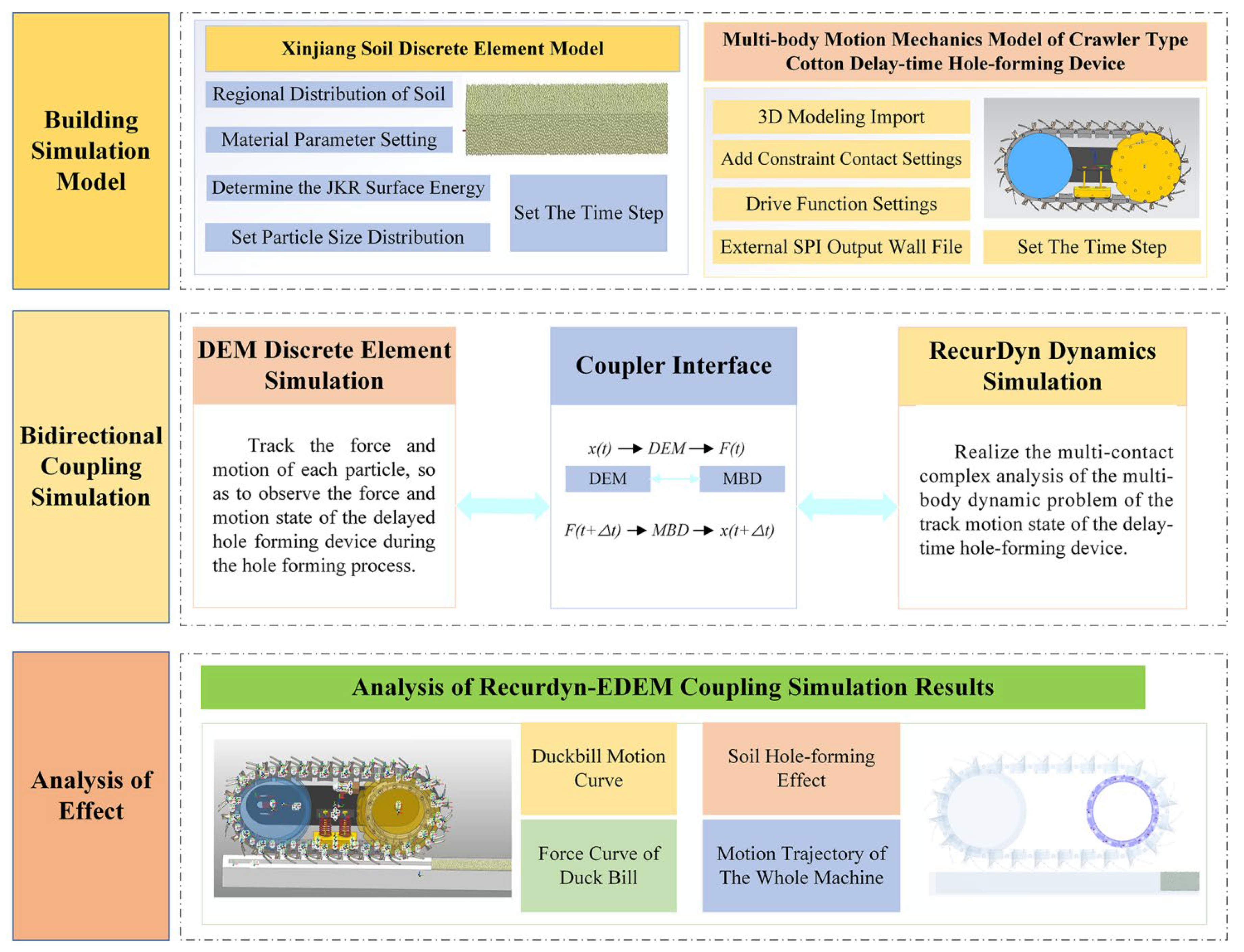
22]. In the process of hole formation, the soil particles are squeezed by the duck bill, and the soil particles collide with each other to form a seed hole, which needs to be analyzed by discrete element method. The duck bill is opened and closed circularly under the action of soil pressure during the working process, and the track block is rotated circularly under the action of sprocket, which needs to be analyzed by multi-body dynamics. The hole-forming effect of the crawler dibbler in the working process is affected by the soil discrete particle system and its own multi-body dynamics system. It is difficult to accurately calculate the hole-forming effect of the mechanism only by mathematical model or single software. In order to observe the movement state of soil in the process of hole formation intuitively and effectively by using DEM-MBD two-way coupling method. In the process of coupling calculation, the multi-body dynamics software initially determines the motion state of the coupling component over time and synchronizes it to the discrete element software. In the discrete element software, the force of the soil particles on the rigid body of the hole-forming mechanism is fed back in real time, and the data is transmitted to the multi-body dynamics model for iterative solution, so as to change the kinematic data of the coupling components and make the simulation results closer to the actual physical behavior. Through this two-way data transmission and in-depth analysis, the interaction mechanism between soil particles and hole formation mechanism can be analyzed more comprehensively. The coupling process and principle are shown in
Figure 6.
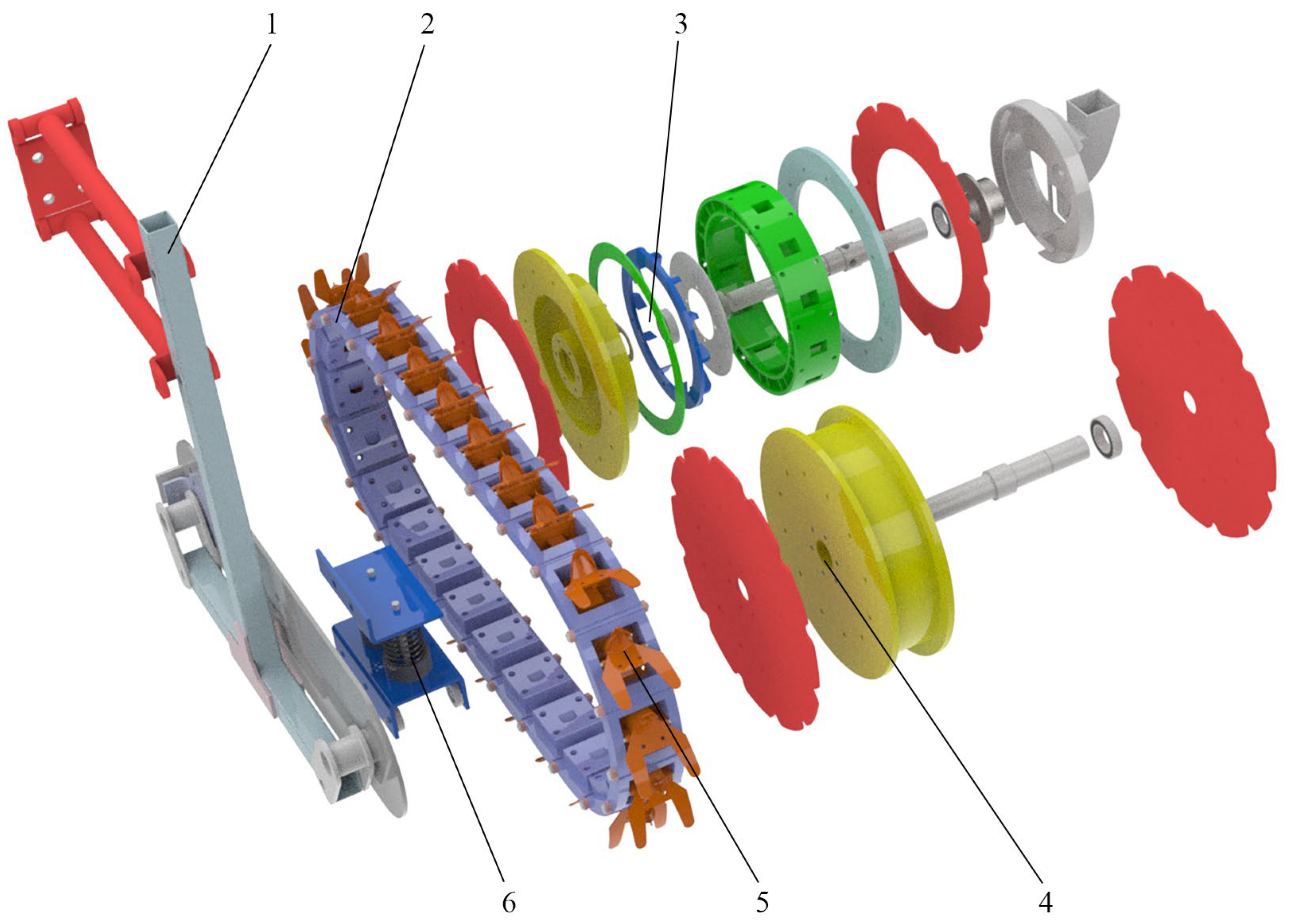
After completing the modeling and assembly of the crawler-type hole-forming mechanism in Soildworks, the assembly is converted into stp format and imported into Recurdyn for dynamic simulation of the whole machine. Simplify the three-dimensional model by retaining only the transmission parts and the parts in contact with the soil, omitting other parts. The properties of the track material are set as resin, the seeding wheel and the auxiliary wheel are aluminum alloy, and the support plate, the tensioning wheel mechanism and the duck bill are steel. Determine the density, Young 's modulus, Poisson 's ratio and other parameters.
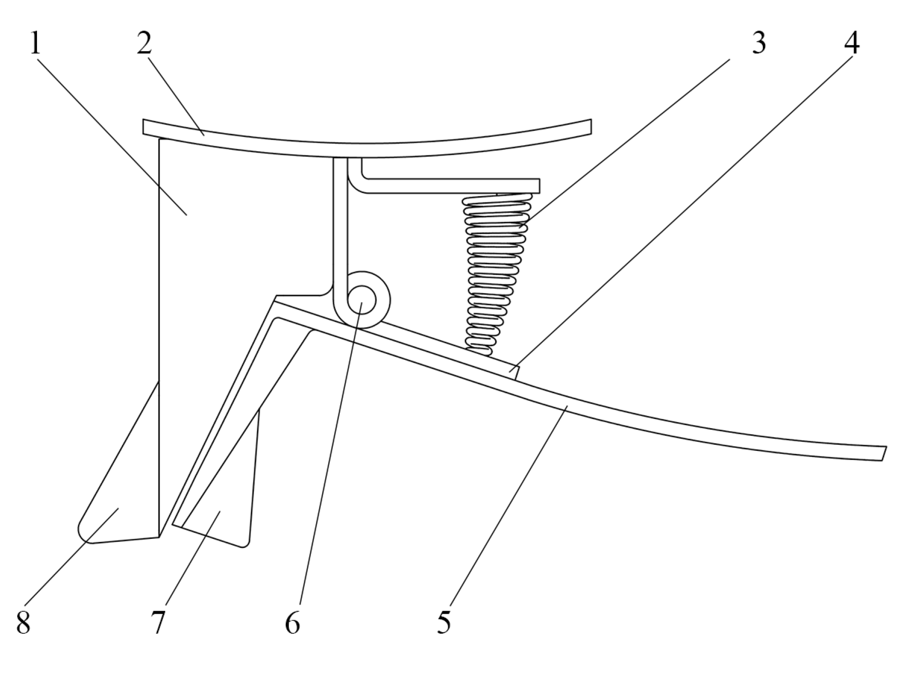
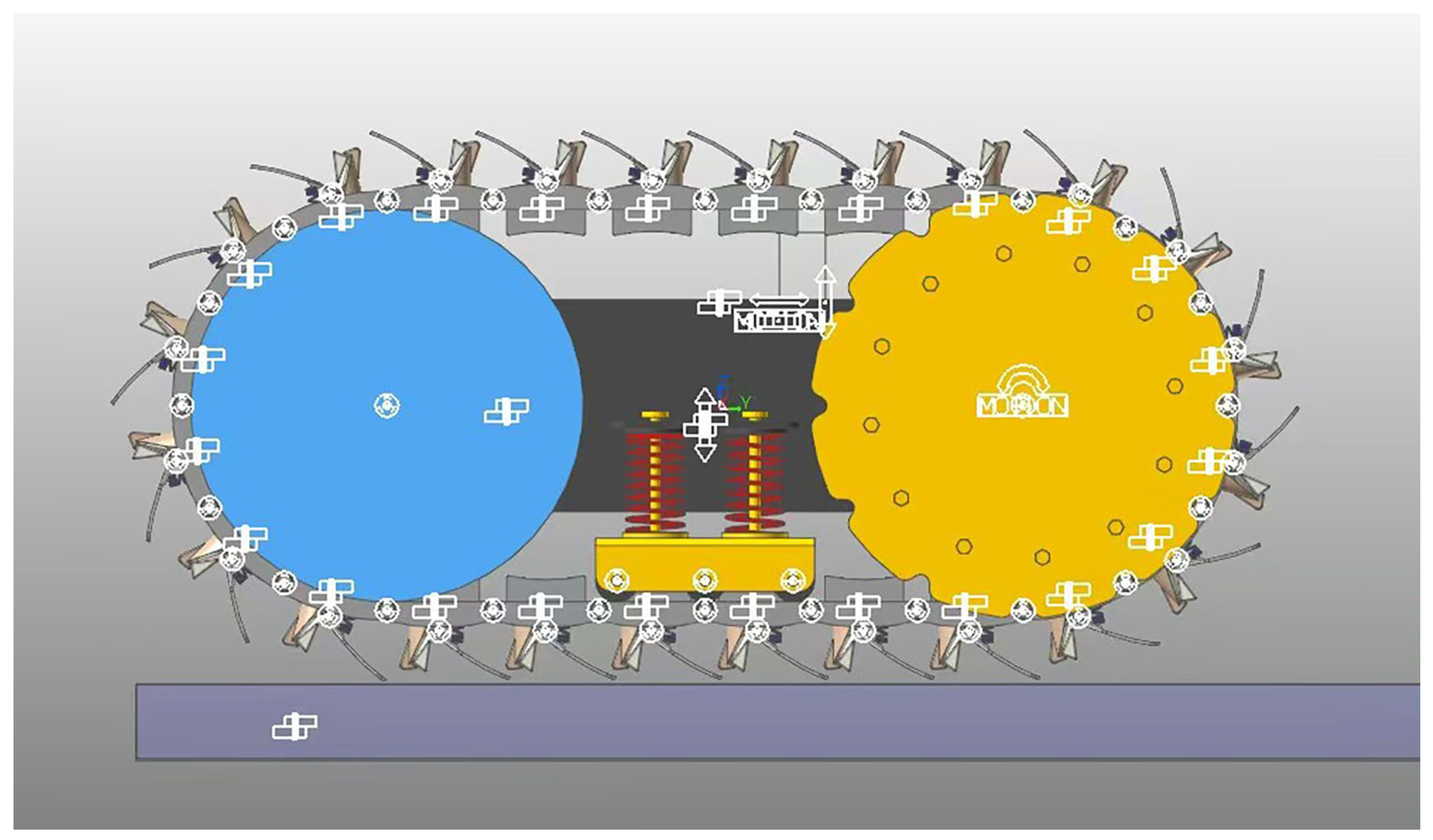
During the working process of the crawler-type hole-forming mechanism, the positioning plate moves horizontally under the action of traction, and the crawler block rotates and engages with the sprocket. When the duck bill in the crawler block contacts with the soil, it opens and closes when it leaves the soil. In order to realize the above motion process, the motion pair is added to the whole machine structure. Rotary pairs are added between each track block, between the track block and the tensioning wheel, between the fixed mouth and the moving mouth of the duck bill, and between the seeding wheel, the auxiliary wheel and the positioning plate. Tension wheel and tension mechanism mounting plate, the road relative to the coordinate system to add a fixed pair. The profiling four-link phase moves vertically with the coordinate system, and the positioning plate adds a moving pair to the road surface. The virtual prototype after constraint is shown in
Figure 7.
Based on the material characteristics, the bearing of the track block and the seeding wheel, the auxiliary wheel and the tensioning mechanism are determined. Moving duck bill and fixed duck bill; the contact between the moving duck beak and the crawler block. The Hertz contact theory formula studies the local stress and strain distribution of two objects after contact, which is determined by the shape and material properties of the contact object. In the numerical simulation, RecurDyn allows a certain degree of penetration when the object is in contact. The contact force between the two objects is simulated by the elastic coefficient
K and the penetration. The elastic coefficient
K is determined by the elastic modulus
E1 and
E2 of the two contact materials, the contact radius
R1 and
R2, and the Poisson's ratio. When the actual contact occurs, the RecurDyn contact force is calculated as follow:
where
fn is formal forc (N),
fns is stiffness forc (N),
fnd is damping force, (N),
δ is penetratio (mm),
C is damping coefficient, N·s/mm.
In order to establish a perfect discrete element contact model of soil particles. The soil physical parameters were measured to determine the soil density of 1.565 g/cm
3, the soil moisture content of 18.3 %, and the soil accumulation angle of 39.6 °. The contact mechanics parameters such as soil JKR surface energy, collision recovery coefficient and dynamic friction are usually unable to be measured directly, and the setting of the above parameters varies greatly in different literatures [
24,
25,
26]. The above parameters directly determine the degree of adhesion between the particles of the soil model and the trajectory of the particles after the mechanical collision. Therefore, the specific values of the above contact mechanical parameters are obtained by the simulation calibration method with the soil accumulation angle as the standard. Finally, the surface energy of soil JKR was determined to be 6.06 J/m
2, the rolling friction coefficient was 0.15, and the collision recovery coefficient was 0.36.
Table 1 shows the design soil parameters.
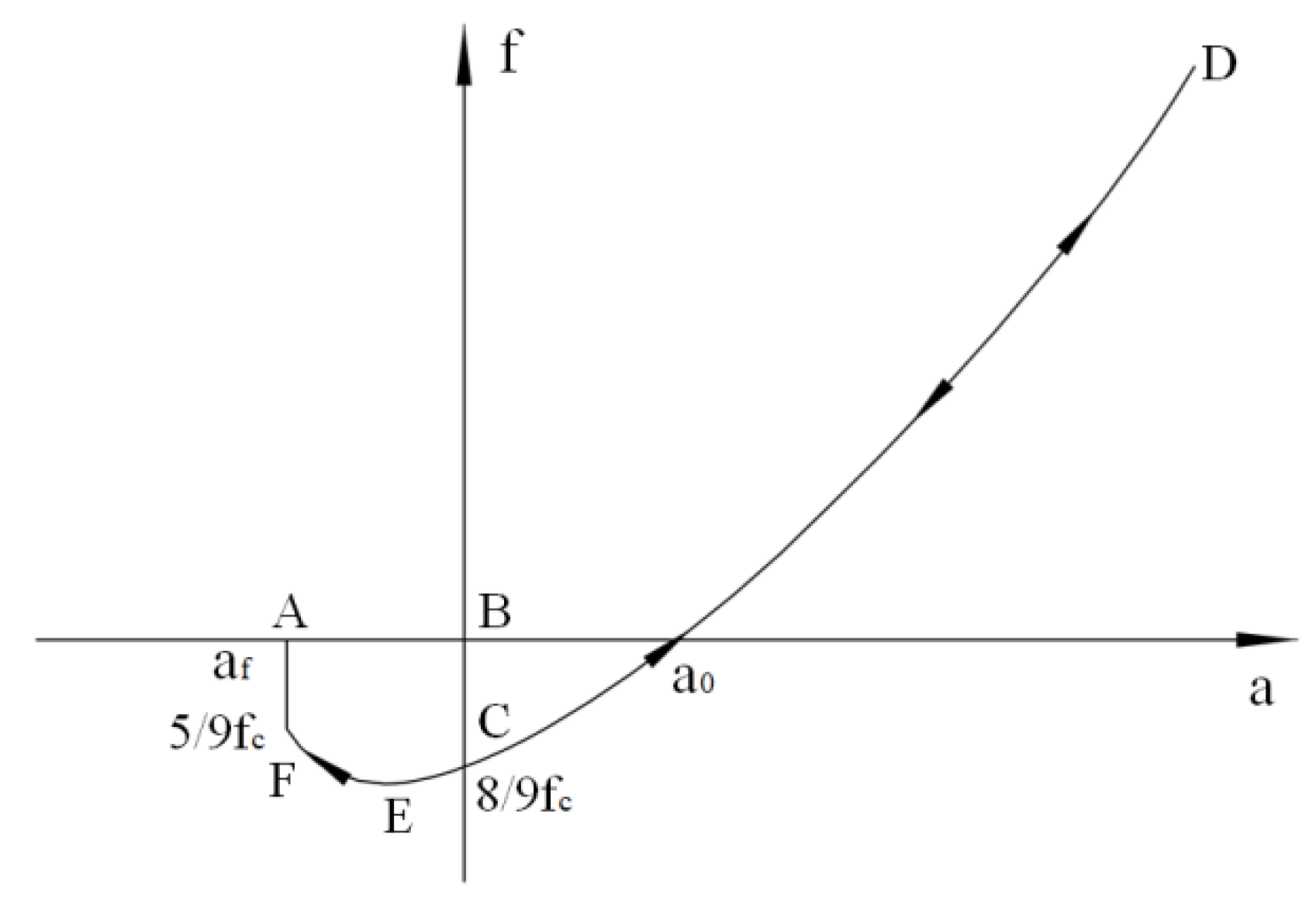
There is an obvious adhesion phenomenon between soil particles in Xinjiang sowing soil. In this study, JKR V2 model is used, which can better reflect the mechanical properties of viscoelastic deformation of adhesive particles. Therefore, compared with the JKR model, it produces a more accurate force calculation. In addition, the study also considers the force effect in the separation process of the adhesion effect between particles. The force-overlap response of the JKR model is shown in
Figure 8. When two elastic and viscous spheres are close to each other, the force acting on the sphere is zero (from A to B). When the two spheres have physical contact (B), the DEM contact between the spheres is established, and the normal contact force decreases immediately (C). In the recovery phase, the stored elastic energy is released and converted into kinetic energy, causing the sphere to move in the opposite direction. When the contact overlap becomes zero (C), all the work done in the loading stage is restored. However, the spheres still adhere to each other, and further work is needed to separate the two spheres. In order to disconnect the contact, a minimum force equal to the breaking force (E) is required, and the contact is disconnected at F.
In order to calculate the adhesion, the
EDEMr needs to be activated and set to be greater than the physical radius of the particle. The calculation formula is as follows:
where
EDEMr is the contact radius of EDEM (mm),
r is the physical radius of particles (mm),
αf is the relative distance of contact fracture, (mm).
The normal contact force in the JKRV2 model is calculated as follows:
where
R is the relative radius (mm),
Γ is the surface energy (J),
γ1 and
γ2 are the surface energy of two spheres (J),
γ12 is the contact surface energy. For the special case of contact between two spheres of the same material,
γ12 is 0, and the interface surface energy becomes
Γ is 2
γ. The maximum normal gap
δc and the maximum adhesion
Fnc of the particles in the calculation interval are as follows:
3.2. Bidirectional Coupling MBD and DEM Simulation Test Scheme and Method
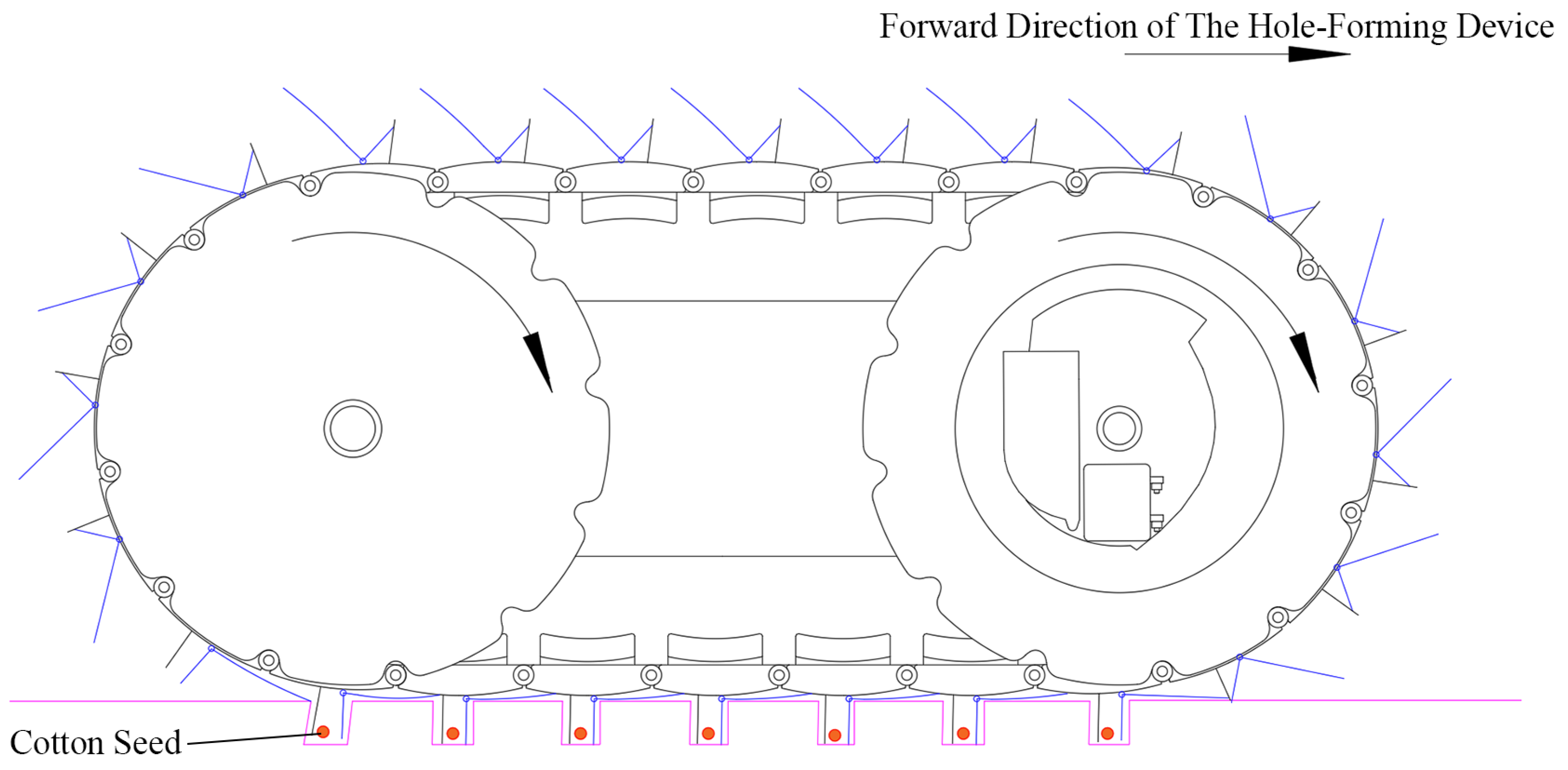
At the initial position of the simulation, the duck bill is in a closed state. A certain gap between the ground and the fixed duck bill is retained to prevent penetration in the initial state model, and the contact force is generated to change the position of the mechanism. In order to make the movement closer to the actual situation, a moving pair moving up and down relative to the Ground is added to the simplified four-bar linkage, and a moving pair moving left and right relative to the four-bar linkage is added to the simplified rear tube, and the square tube is fixed with the positioning plate. Therefore, the whole machine can only move along the plane with four degrees of freedom. The square tube moving pair is defined along the vertical direction, and the displacement Motions function is step (time, 0, 0, 0.1, -50.5). The four-link moving pair is defined along the horizontal direction, and the velocity Motions function is IF (time-0.2 : 0, 0, 1666.7). That is, the moving speed of the whole machine is 0 before 0.2 s, and the displacement of the whole machine along the negative direction of the z-axis is 50.5 mm in the vertical downward direction at 0.1 s. After the displacement, it contacts with the ground, and the duck bill opens and stabilizes for 0.1 s. After 0.2 s, the four-bar linkage moves horizontally to the right along the positive direction of the y-axis at a speed of 1666.7 mm/s or 6.0 km/h. Under the action of friction, the duck bill drives the track block to rotate, and then drives the seeding wheel to rotate synchronously, and the hole-forming mechanism begins to work.
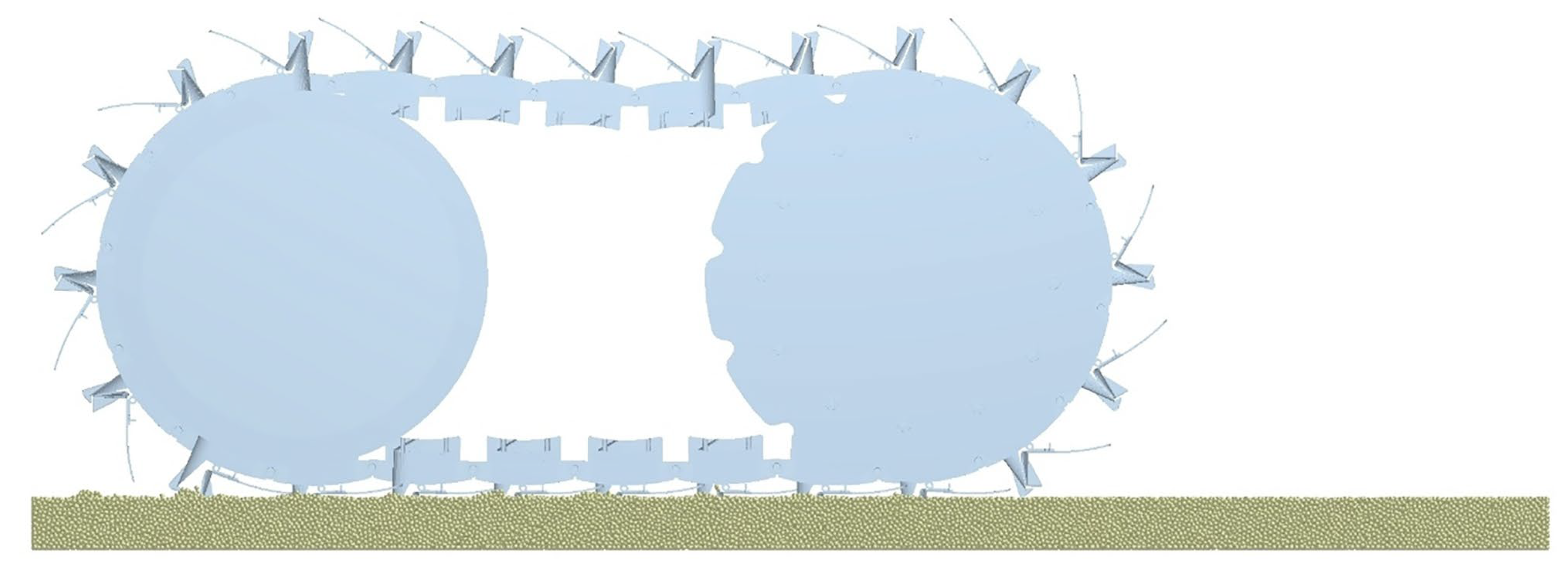
The Geometry imported by the wall file in the EDEM simulation phase is always consistent with the Body motion process in RecurDyn. After the whole machine is stable in contact with the road surface, it gradually moves to the soil trough EDEM particle group. At this time, the duck bill is inserted into the soil in turn, and the spring compresses the duck bill mouth to open to form a seed hole. The contact information, mechanism force and motion trajectory of the whole machine are determined by the parameters set by RecurDyn and EDEM. The process of the whole machine into the soil is shown in
Figure 9.
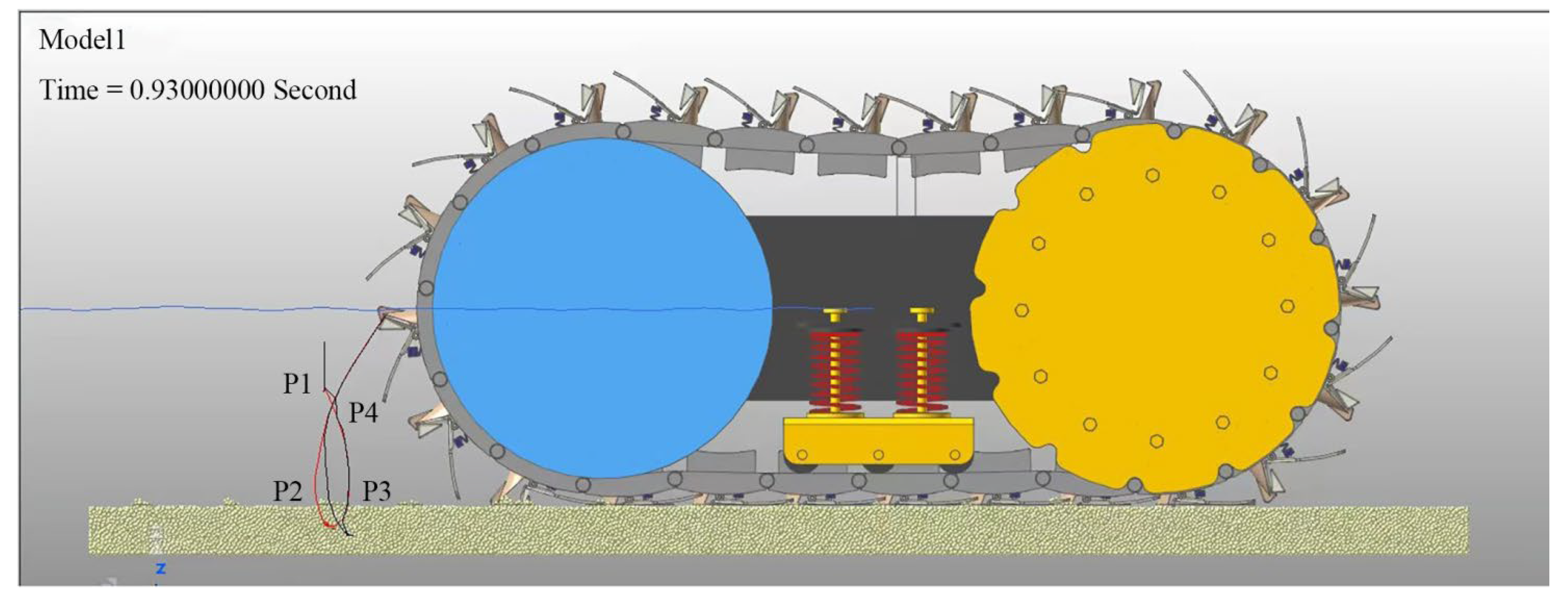
In order to visually display the motion trajectory of the duck bill and the working stability of the whole machine, Marker points are added at the end of the fixed duck bill and the end of the moving duck respectively, and the motion trajectories are displayed with red and black lines respectively. Marker points are added to the centroid of the positioning plate, and the trajectory is displayed in blue lines. It can be seen from
Figure 10 that the trajectory of the duck bill can be divided into three sections.
P1P2 section: Before P1 point, the whole machine advanced vertical decline, static and stable for a period of time after contact with the soil, so the duck bill and the fixed mouth trajectory before P1 point is a vertical downward straight line. The red line coincides with the black line. At this stage, the duck bill rotates to contact with the soil. Before contact, the duck bill closes under the action of spring.
P2P3 section: The red line is separated from the black line and has the maximum distance at the end of the trajectory. At this stage, the duck bill enters the soil, and under the action of soil pressure, the duck bill gradually opens and remains open during the extension period. In the process of duck bill leaving the soil, the moving beak swallow tail is fitted with the track block, and the duck bill remains open.
P3P4 section: The red line and the black line gradually coincide. At this stage, the duck bill gradually leaves the soil, the pressure of the spring is reduced, and the duck bill gradually closes. The overall trajectory is a trochoid, and the trajectory coincides and enters the next motion cycle.
The whole stage of the blue line has been a smooth straight line, indicating that the whole machine is stable.
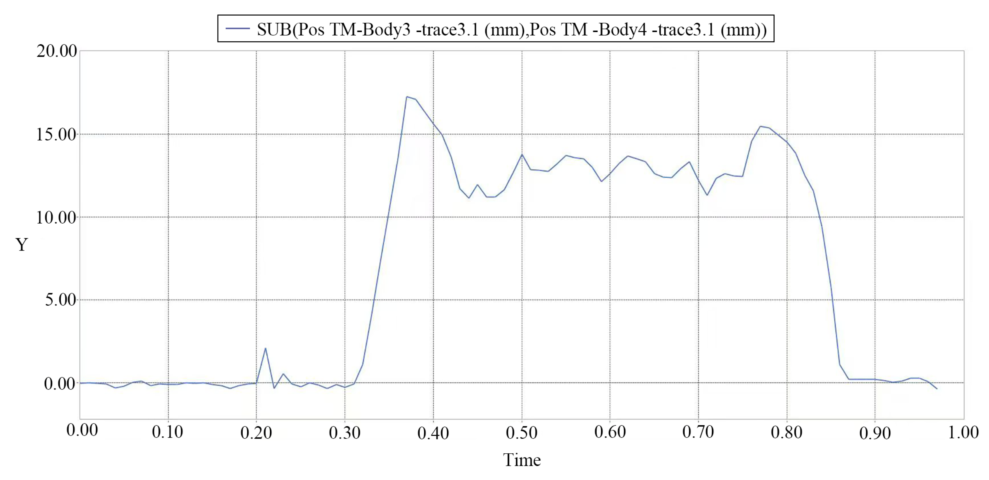
In order to better analyze the trajectory of the duck bill changing with time, the motion curve of the end of the fixed duck bill and the end of the moving duck bill is derived in RecurDyn Plot, and the two are subtracted to obtain the curve of the opening distance of the duck bill changing with time as shown in
Figure 11.
As shown in the diagram, before 0.30 s, the duck bill is closed, and the opening distance of the duck bill is 0 mm. After 0.32 s, the duck bill was gradually opened by soil pressure, reaching a maximum of 15.6 mm at 0.36 s, and then decreased slightly to maintain a fluctuation of about 14 mm. Because the dovetail and the crawler block change from fitting with the crawler block to contacting with the crawler block at the end during the extension period, the opening degree is reduced, and under the action of the spring of the damping mechanism, the dovetail has a certain degree of up and down vibration. At 0.76 s, the opening distance is as large as 15.2 mm, and then gradually decreases to 0 and remains unchanged. It can be seen that the opening time of the duck bill is extended to 0.46 s, which provides sufficient time for the falling of cotton seeds. The opening distance of duck bill was 13.4~15.6 mm, which was consistent with the calculated optimal opening value. The above simulation results show that the hole-forming mechanism has high feasibility in the performance of delaying hole-forming and increasing seed-dropping time.
3.2.1. Single Factor Simulation Test
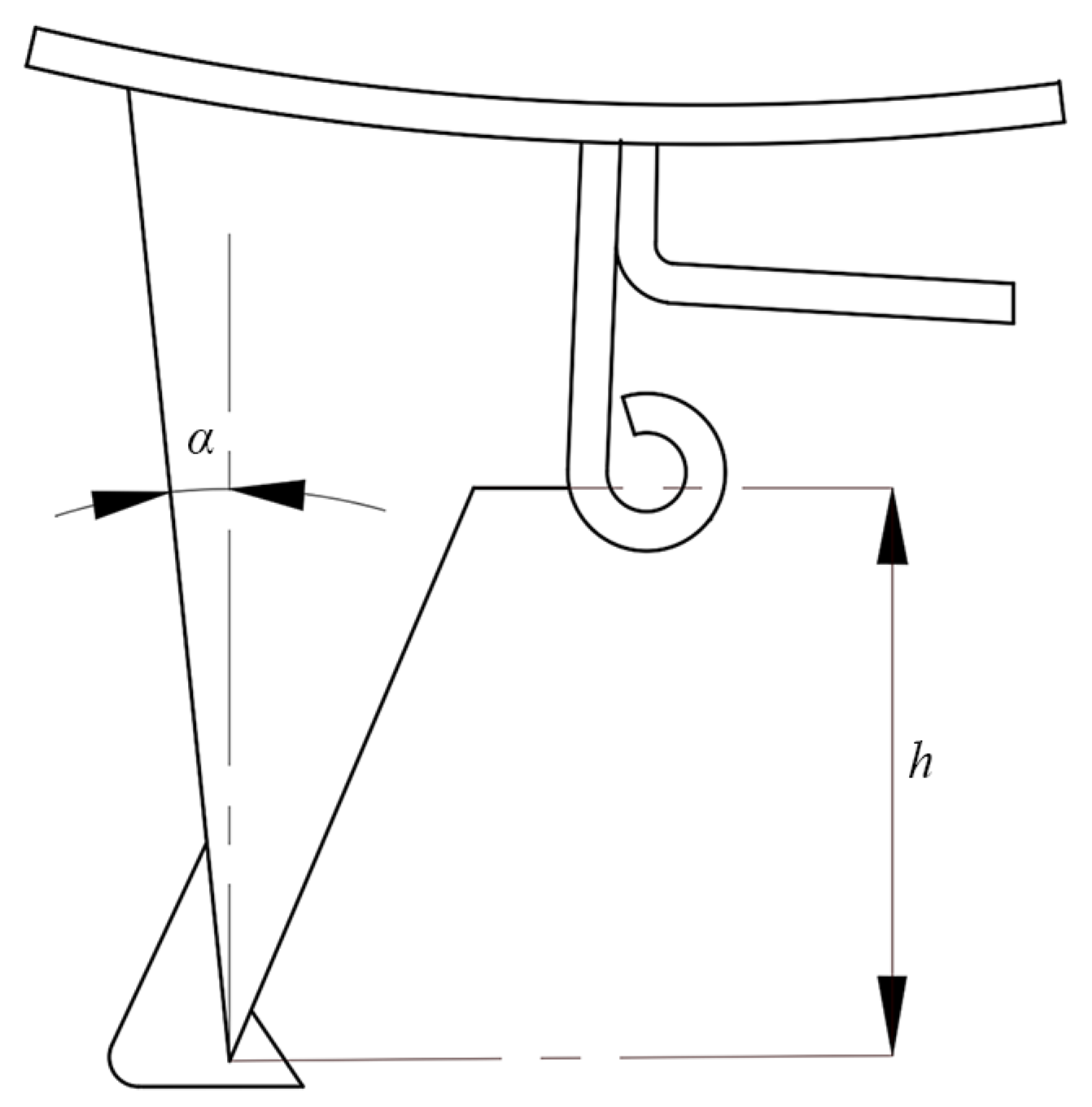
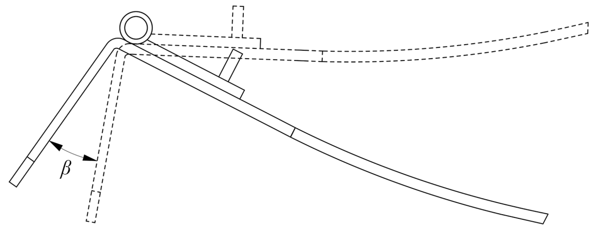
The forward speed of the simulation machine is set to 6 km/h. The soil particles have typical discreteness, and the soil particles change dynamically when they interact with the duck bill, so the quality of the hole changes accordingly after the speed is increased. Therefore, the size of the duck bill structure was adjusted to ensure the quality of the hole-formation. Referring to the structural parameters of the key components and the analysis of the cavitation trajectory of the mechanism, The fixed the tilt angle of the duck bill α, the depth of the duck bill hole-forming into the soil h and the angle of rotation of the moving duck bill β are selected as the experimental factors to carry out the simulation test.
The size of the hole includes the transverse size of the hole, the longitudinal size of the hole and the depth of the hole. The transverse size of the hole is consistent with the width of the duck 's beak, and the value is relatively fixed [
27]. Therefore, the evaluation of the effect of the hole is mainly through the EDEM post-processing to measure the effective depth of the hole and the longitudinal length of the hole. The smaller the size of the hole is, the less the evaporation of water in the soil is, and the smaller the size of the hole is, which is conducive to warming and preserving moisture.
The influence of the inclination angle of the fixed duck bill on the quality of the hole is selected. The depth of the duck bill hole-forming into the soil is
h = 40 mm, the middle value of the angle of rotation of the moving duck bill is
β = 32 °, and the fixed the tilt angle of the duck bill is
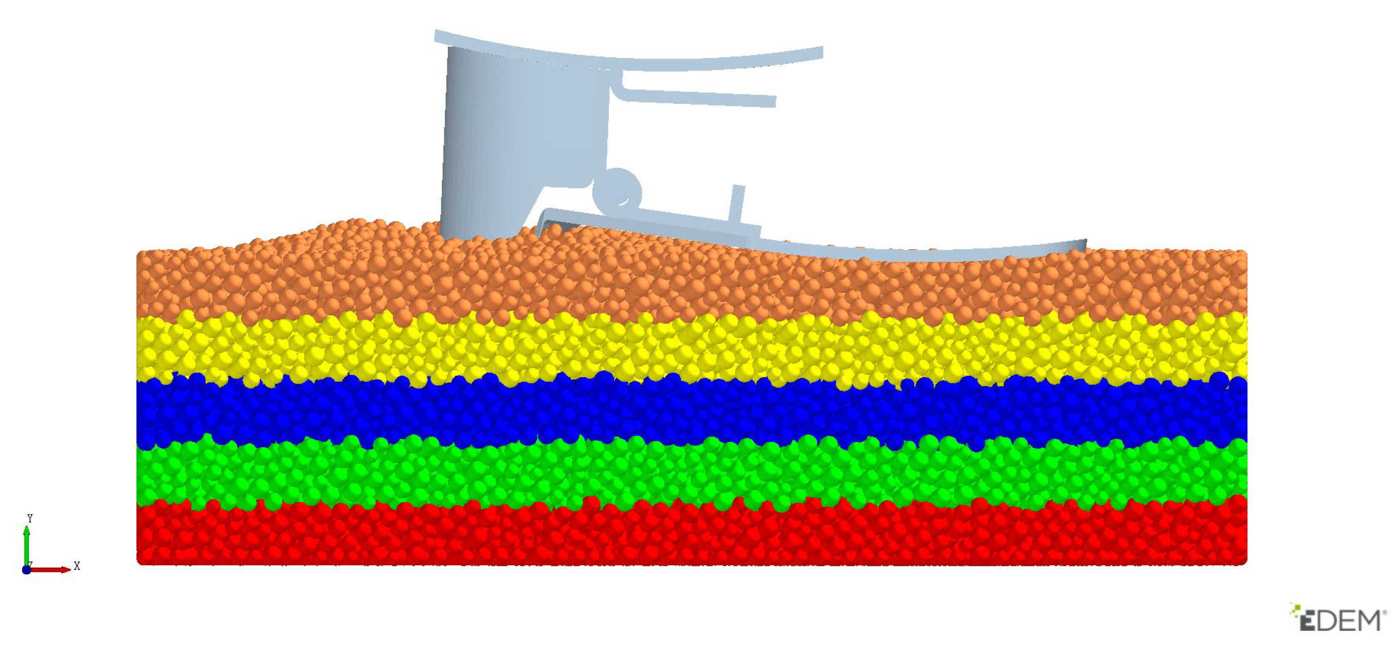
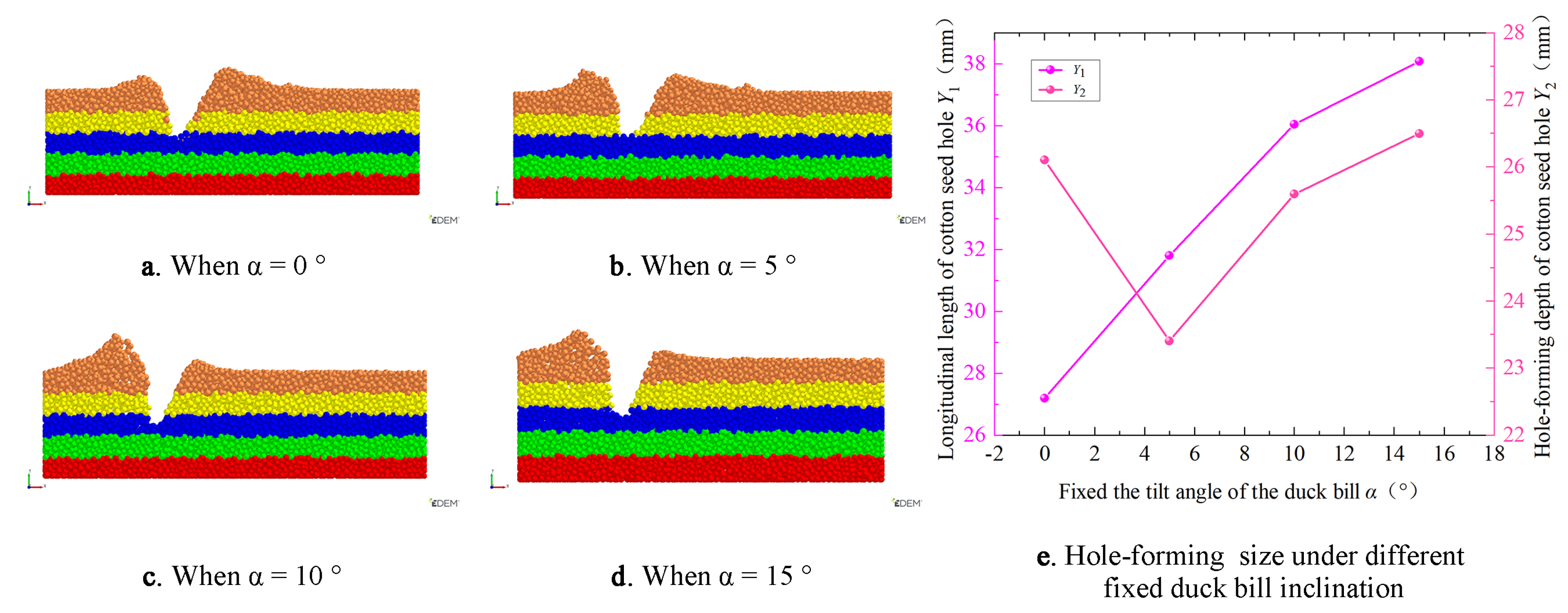
α = 0 °, 5 °, 10 °, 15 °. The position of soil particles changes in real time during the process of hole formation. In order to more intuitively observe the movement law of soil particles after duck bill extrusion, the longitudinal length of the hole and the depth of the hole were recorded, and the soil particles were not refluxed. In the EDEM post-processing interface, the 'Geometry Bin' function is used to divide the soil into five regions along the vertical soil direction. In 'Particle Seletions', different colors were added to soil particles in different regions, and the color remained unchanged after the position of particles in the same region was changed. The results are shown in
Figure 12. The 'Clipping' tool was added to cut the soil from the vertical surface to a 10 mm soil layer along the center line, so as to observe the effect of the hole.
The effect of hole formation under different fixed duck bill inclination angles is shown in
Figure 13. The post-processing 'Ruler' tool was used to measure the longitudinal length of the seed hole and the depth of the seed hole after the duck bill left the soil. From the diagram, it can be seen that the longitudinal length of the seed hole increases with the increase of the fixed duck bill inclination angle, and the depth of the seed hole increases first and then decreases with the increase of the fixed duck bill inclination angle. The reason is that the inclination angle of the duck bill increases, the contact time with the soil during the formation of the duck bill is long, and the amount of soil on the side wall of the duck bill is large, so the longitudinal length of the seed hole increases. When the inclination angle of the fixed duck bill is small or large, the extrusion of the soil by the fixed or moving duck bill is more obvious, the soil particles tend to accumulate to one side, the edge height of the seed hole increases, and the depth of the seed hole increases. Considering the soil disturbance and the effect of hole formation, the duck bill inclination angles of 0 °, 5 °and 10 ° were selected for the subsequent orthogonal test.
The influence of the depth of the duck bill hole-forming into the soil on the quality of the hole was selected, and the intermediate value of the fixed the tilt angle of the duck bill
α = 5 ° was selected. The middle value of the angle of rotation of the moving duck bill is
β = 32 °, the depth of the duck bill hole-forming into the soil is
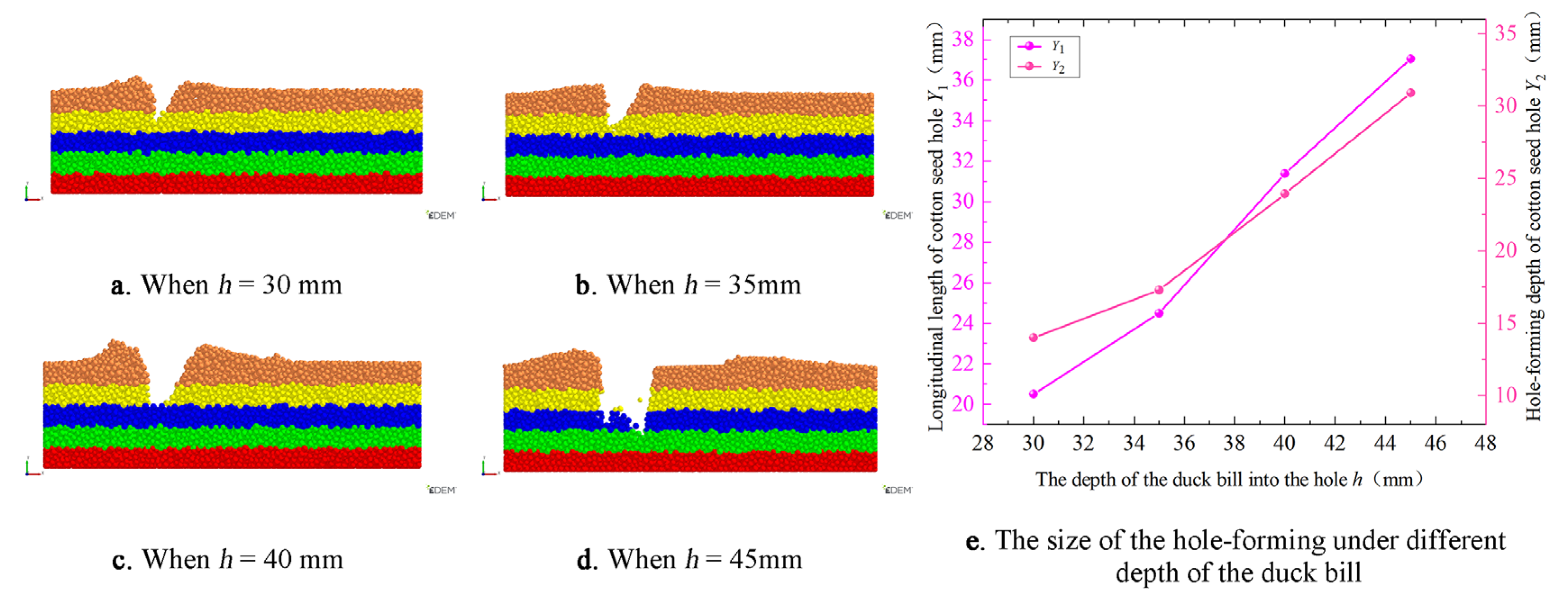
h =30mm, 35mm, 40mm, 45mm. The influence of the depth of the duck bill hole-forming into the soil on the effect of hole formation was analyzed. The longitudinal length and effective depth of the seed hole were measured. The change of the effect of the hole with the depth of the duck bill is shown in
Figure 14.
It can be seen from the figure that as the depth of the duck bill increases, the contact area and contact time between the duck bill wall and the soil particles increase, and the longitudinal length and depth of the hole after the duck bill leaves the soil increase. Considering the soil disturbance and the effect of hole formation, the duck bill depth of 35 mm, 40 mm and 45 mm was selected for the subsequent orthogonal test.
The influence of the rotation angle of the moving duck bill on the quality of the hole is selected, and the median value of the inclination angle of the fixed duck bill is
α = 5 °. The depth of the duck bill hole-forming into the soil is
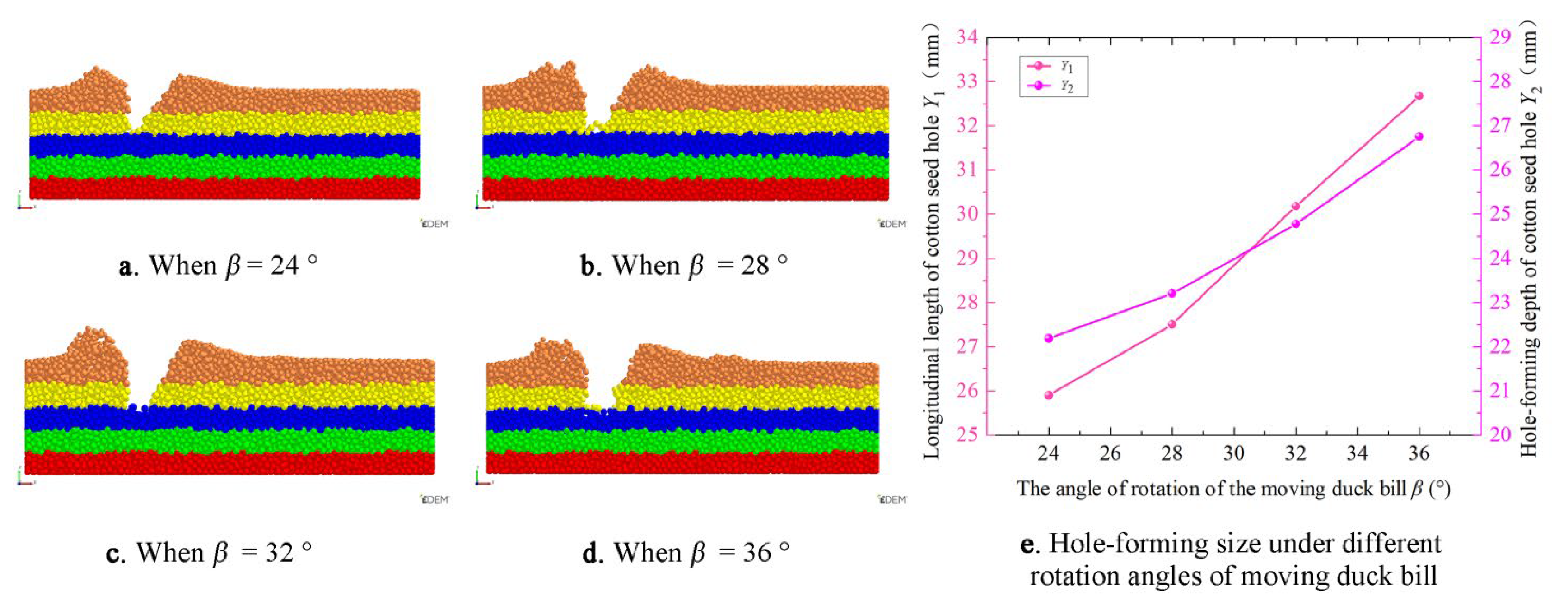
h =40mm., and the angle of rotation of the moving duck bill is β = 24 °, 28 °, 32 °, 36 °. The influence of duck bill rotation angle on soil disturbance was analyzed. The longitudinal length and effective depth of the seed hole were measured. The change of the effect of the hole with the angle of rotation of the moving duck bill is shown in
Figure 15.
From the diagram, it can be seen that with the increase of the turning angle of the moving duck bill, the longitudinal length of the seed hole and the depth of the hole are increased. The reason is that with the increase of the turning angle of the moving duck bill, the range of the fixed duck bill is unchanged, the degree of rotation of the moving duck bill around the duck bill pin increases, the height difference between the end of the fixed duck bill and the end of the fixed duck bill increases, and the depth of the seed hole increases. At the same time, the soil disturbance near the movable duck bill increases, the soil is enhanced by the shearing and squeezing of the duck bill, and the offset of the soil to the movable duck bill side increases during the hole formation process, resulting in an increase in the longitudinal length. Considering the soil disturbance and the effect of hole formation, the duck bill rotation angles of 28 °, 32 ° and 36 ° were selected for subsequent experiments.
3.2.2. Quadratic Regression Orthogonal Rotation Combination Simulation Test Scheme
In order to further study the influence of The fixed the tilt angle of the duck bill
α(
A), the depth of the duck bill hole-forming into the soil
h(
B) and the angle of rotation of the moving duck bill
β(
C) on the working performance of the crawler-type delayed hole formation mechanism. Based on the parameter range determined by the structural parameter design of the key components and the single factor simulation test, the influence of each factor and its interaction on the working performance of the hole formation mechanism is further studied. According to the single factor test of the project team, the value range of each factor is determined, and the experimental design is carried out according to the Box-Benhnken center combination design theory. The level coding of each factor is shown in
Table 2. Through the relevant high-level papers and the above single-factor test, longitudinal length of cotton seed hole
Y1 and hole-forming depth of cotton seed hole
Y2 were selected as the experimental hole formation indexes of the effect of the seed hole, and the specific values were measured by EDEM post-processing.
3.3. Bench Test Conditions and Methods
It is an important step to further improve the sample to verify the actual operation and the performance of the crawler-type delay hole formation mechanism. This experiment was carried out in the soil trough laboratory. The test was carried out according to the test standards required by JB/T7732-2023 'film seeder' [
28] and GB/T6973-2005 'single grain ( precision ) seeder test method' [
29] and high-level papers related to the quality of the hole. The main purpose is to test the working performance of the crawler delay hole-forming mechanism and the quality of the hole formation operation when the forward speed of the machine is increased to 6 km/h. By comparing the simulation results under the optimal conditions of each factor with the results of the soil trough bench test of the machine. The longitudinal length of cotton seed hole
Y1 and hole-forming depth of cotton seed hole
Y2 were used to evaluate and verify the hole-forming performance of the delayed hole-forming device. Taking the hole dislocation rate
Hc and the hole distance qualified rate
Hx of the crawler type delay hole forming device as the evaluation standard of the working quality, to judge whether its working performance meets the national standard. At the same time, according to the results of the soil bin verification test, it provides a reference for the subsequent improvement and optimization of the prototype performance.
where
Ch is the number of misaligned membrane pores,
Xh is the qualified number of hole distance,
f is the total determination of membrane pore number.
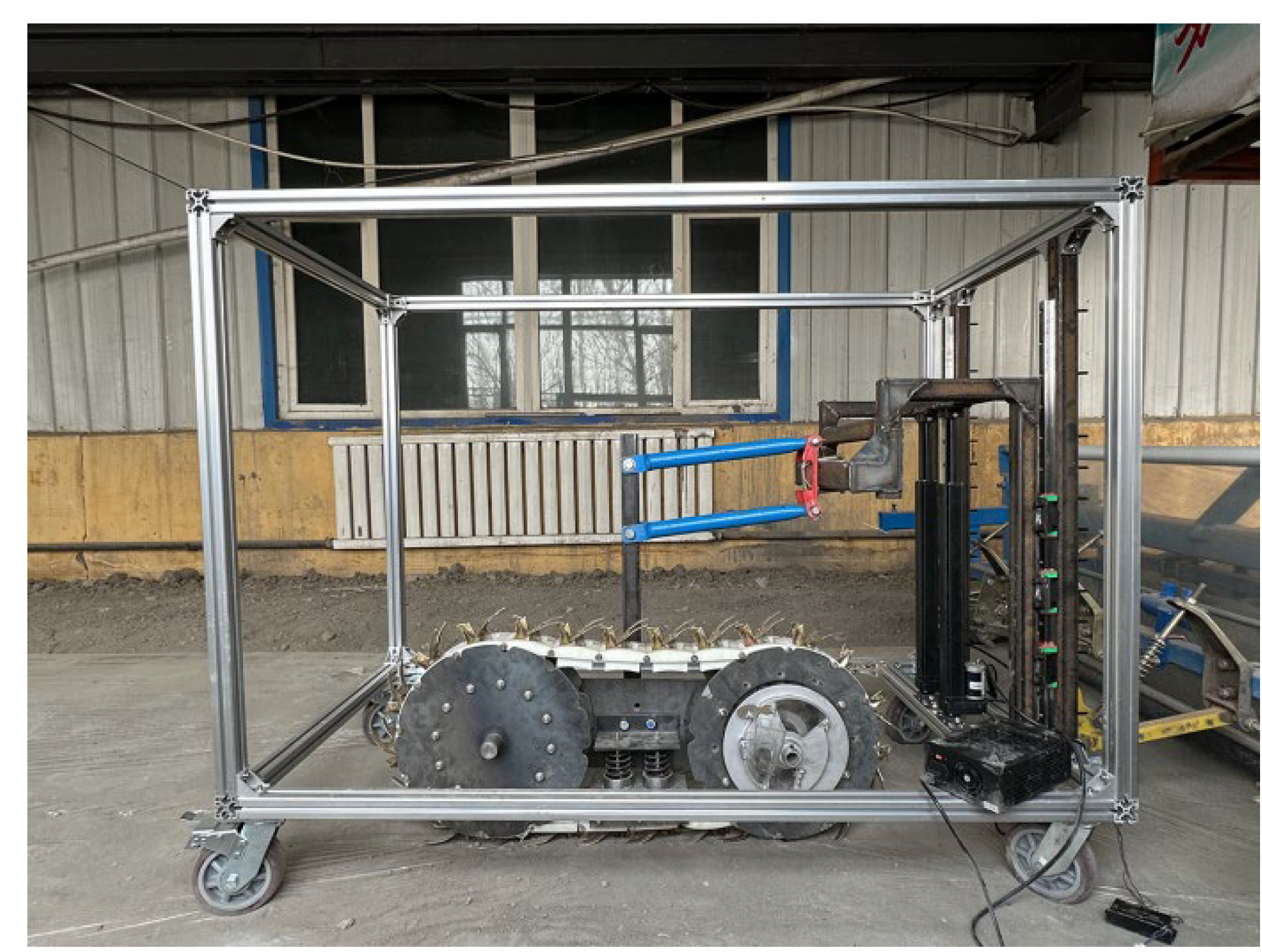
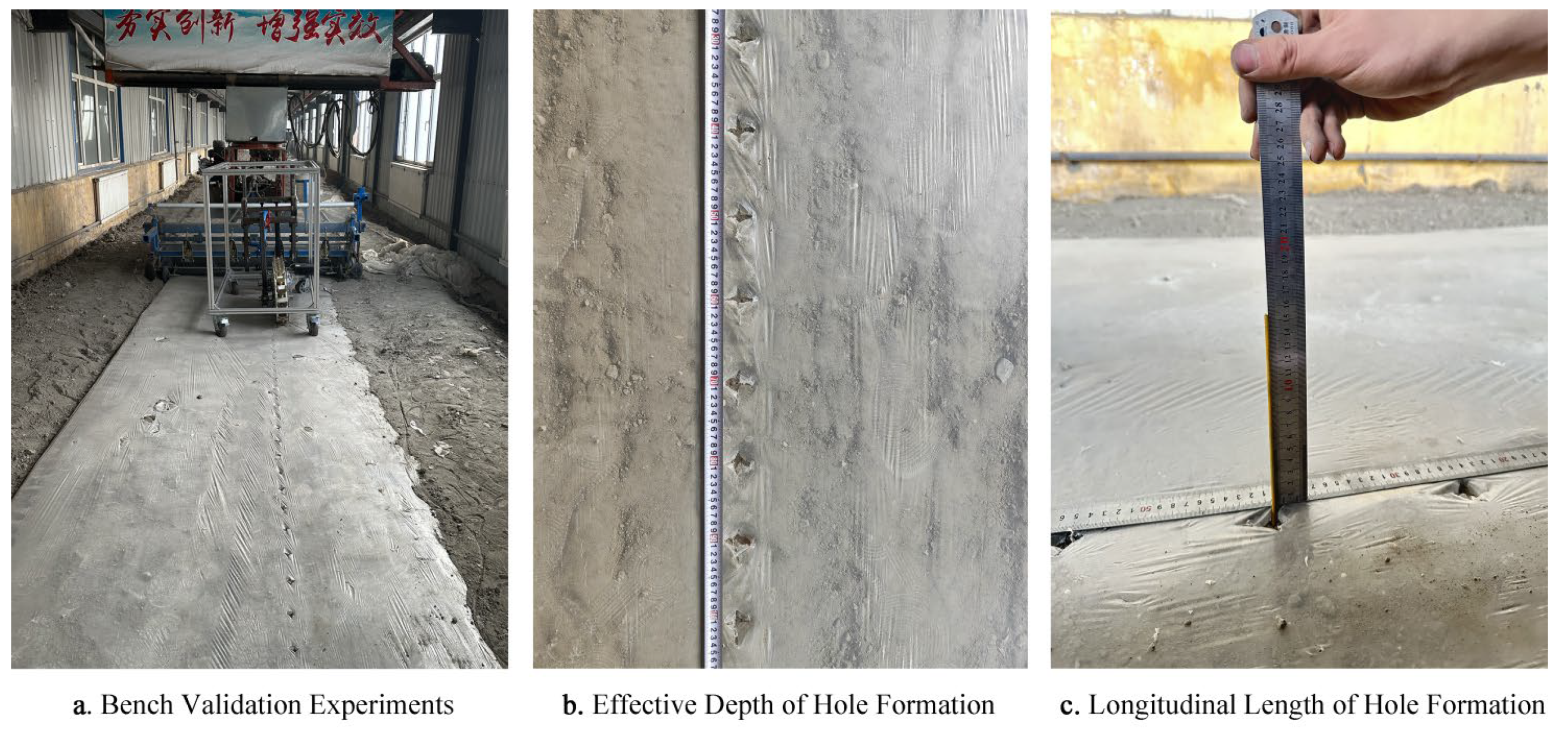
On March 5,2024 in Xinjiang Xin Changsheng Agricultural Machinery Co., Ltd. soil trough bench test, as shown in
Figure 16. The soil was leveled by rotary tillage in the early stage, and the soil type was sandy loam. The test soil bin is 150 m long and 10 m wide. The main instruments of the test equipment are: crawler-type cotton time-delay hole-forming device prototype, 2MBJ film laying and soil preparation assembly, high-speed camera, tape, steel ruler, steel swab and so on. Before the test, the 2MBJ film-paving and soil preparation assembly was used to complete the film-paving operation. During the test, the forward speed of the prototype was set to 6km/h, the working parameters of the key components were set to the values under the optimal simulation conditions, and the forward distance was set to 15 m each time. The velocity is not stable in the initial and stop motion stages of the time-delay hole-forming device. Therefore, only the test soil tank selected for the test is composed of three parts: starting area, measuring area and parking area. The length of the test area is 10 m, and the start-up area and parking area are both 2.5 m. Theoretically, 100 holes can be formed in the measurement area (10m).
