Submitted:
06 June 2024
Posted:
07 June 2024
You are already at the latest version
Abstract
Keywords:
1. Introduction
2. Materials and Methods
3. Results and Discussion
3.1. DNT/Cellulose and DNT/Epoxy Nanocomposites
3.2. Calcium-Silicate-Hydrates and Boron Nitride Nanotube Nanocomposites
4. Conclusions
Author Contributions
Funding
Institutional Review Board Statement
Informed Consent Statement
Data Availability Statement
Acknowledgments
Conflicts of Interest
References
- Egbo, M.K. A Fundamental Review on Composite Materials and Some of Their Applications in Biomedical Engineering. Journal of King Saud University - Engineering Sciences 2020. [Google Scholar] [CrossRef]
- Li, W.; Dong, W.; Guo, Y.; Wang, K.; Shah, S.P. Advances in Multifunctional Cementitious Composites with Conductive Carbon Nanomaterials for Smart Infrastructure. Cement and Concrete Composites 2022, 128, 104454. [Google Scholar] [CrossRef]
- Umar, K.; Yaqoob, A.A.; Ibrahim, M.N.M.; Parveen, T.; Safian, M.T. Chapter Thirteen - Environmental Applications of Smart Polymer Composites. In Smart Polymer Nanocomposites; Bhawani, S.A., Khan, A., Jawaid, , M., Eds.; Woodhead Publishing Series in Composites Science and Engineering; Woodhead Publishing, 2021; pp. 295–312. ISBN 978-0-12-819961-9. [Google Scholar]
- Ali, A.; Andriyana, A. Properties of Multifunctional Composite Materials Based on Nanomaterials: A Review. RSC Advances 2020, 10, 16390–16403. [Google Scholar] [CrossRef] [PubMed]
- Bekzhanova, Z.; Memon, S.A.; Kim, J.R. Self-Sensing Cementitious Composites: Review and Perspective. Nanomaterials 2021, 11, 2355. [Google Scholar] [CrossRef] [PubMed]
- Basquiroto de Souza, F.; Yao, X.; Lin, J.; Naseem, Z.; Tang, Z.Q.; Hu, Y.; Gao, W.; Sagoe-Crentsil, K.; Duan, W. Effective Strategies to Realize High-Performance Graphene-Reinforced Cement Composites. Construction and Building Materials 2022, 324, 126636. [Google Scholar] [CrossRef]
- Sreenivasulu, B.; Ramji, Br.; Nagaral, M. A Review on Graphene Reinforced Polymer Matrix Composites. Materials Today: Proceedings 2018, 5, 2419–2428. [Google Scholar] [CrossRef]
- Díez-Pascual, A.M. Carbon-Based Polymer Nanocomposites for High-Performance Applications. Polymers 2020, 12, 872. [Google Scholar] [CrossRef] [PubMed]
- Harussani, M.M.; Sapuan, S.M.; Nadeem, G.; Rafin, T.; Kirubaanand, W. Recent Applications of Carbon-Based Composites in Defence Industry: A Review. Defence Technology 2022, 18, 1281–1300. [Google Scholar] [CrossRef]
- Wang, Z.; Liu, L.; Zhang, Y.; Huang, Y.; Liu, J.; Zhang, X.; Liu, X.; Teng, H.; Zhang, X.; Zhang, J.; et al. A Review of Graphene-Based Materials/Polymer Composite Aerogels. Polymers (Basel) 2023, 15, 1888. [Google Scholar] [CrossRef] [PubMed]
- Seydibeyoğlu, M.Ö.; Dogru, A.; Wang, J.; Rencheck, M.; Han, Y.; Wang, L.; Seydibeyoğlu, E.A.; Zhao, X.; Ong, K.; Shatkin, J.A.; et al. Review on Hybrid Reinforced Polymer Matrix Composites with Nanocellulose, Nanomaterials, and Other Fibers. Polymers 2023, 15, 984. [Google Scholar] [CrossRef]
- Latif, Z.; Ali, M.; Lee, E.-J.; Zubair, Z.; Lee, K.H. Thermal and Mechanical Properties of Nano-Carbon-Reinforced Polymeric Nanocomposites: A Review. J. Compos. Sci. 2023, 7, 441. [Google Scholar] [CrossRef]
- Amraei, J.; Jam, J.E.; Arab, B.; Firouz-Abadi, R.D. Modeling the Interphase Region in Carbon Nanotube-reinforced Polymer Nanocomposites. Polymer Composites 2019, 40. [Google Scholar] [CrossRef]
- Fitzgibbons, T.C.; Guthrie, M.; Xu, E.; Crespi, V.H.; Davidowski, S.K.; Cody, G.D.; Alem, N.; Badding, J.V. Benzene-Derived Carbon Nanothreads. Nature Mater 2015, 14, 43–47. [Google Scholar] [CrossRef]
- Li, X.; Baldini, M.; Wang, T.; Chen, B.; Xu, E.; Vermilyea, B.; Crespi, V.H.; Hoffmann, R.; Molaison, J.J.; Tulk, C.A.; et al. Mechanochemical Synthesis of Carbon Nanothread Single Crystals. J. Am. Chem. Soc. 2017, 139, 16343–16349. [Google Scholar] [CrossRef]
- Duan, P.; Li, X.; Wang, T.; Chen, B.; Juhl, S.J.; Koeplinger, D.; Crespi, V.H.; Badding, J.V.; Schmidt-Rohr, K. The Chemical Structure of Carbon Nanothreads Analyzed by Advanced Solid-State NMR. J. Am. Chem. Soc. 2018. [Google Scholar] [CrossRef]
- Wang, T.; Duan, P.; Xu, E.-S.; Vermilyea, B.; Chen, B.; Li, X.; Badding, J.V.; Schmidt-Rohr, K.; Crespi, V.H. Constraining Carbon Nanothread Structures by Experimental and Calculated Nuclear Magnetic Resonance Spectra. Nano Lett. 2018, 18, 4934–4942. [Google Scholar] [CrossRef]
- Nobrega, M.M.; Teixeira-Neto, E.; Cairns, A.B.; Temperini, M.L.A.; Bini, R. One-Dimensional Diamondoid Polyaniline-like Nanothreads from Compressed Crystal Aniline. Chem. Sci. 2018, 9, 254–260. [Google Scholar] [CrossRef]
- Fanetti, S.; Nobrega, M.M.; Teixeira-Neto, E.; Temperini, M.L.A.; Bini, R. Effect of Structural Anisotropy in High-Pressure Reaction of Aniline. J. Phys. Chem. C 2018, 122, 29158–29164. [Google Scholar] [CrossRef]
- Li, X.; Wang, T.; Duan, P.; Baldini, M.; Huang, H.-T.; Chen, B.; Juhl, S.J.; Koeplinger, D.; Crespi, V.H.; Schmidt-Rohr, K.; et al. Carbon Nitride Nanothread Crystals Derived from Pyridine. J. Am. Chem. Soc. 2018, 140, 4969–4972. [Google Scholar] [CrossRef]
- Fanetti, S.; Santoro, M.; Alabarse, F.; Enrico, B.; Bini, R. Modulating the H-Bond Strength by Varying the Temperature for the High Pressure Synthesis of Nitrogen Rich Carbon Nanothreads. Nanoscale 2020, 12, 5233–5242. [Google Scholar] [CrossRef]
- Oburn, S.M.; Huss, S.; Cox, J.; Gerthoffer, M.C.; Wu, S.; Biswas, A.; Murphy, M.; Crespi, V.H.; Badding, J.V.; Lopez, S.A.; et al. Photochemically Mediated Polymerization of Molecular Furan and Pyridine: Synthesis of Nanothreads at Reduced Pressures. J. Am. Chem. Soc. 2022. [Google Scholar] [CrossRef]
- Biswas, A.; Ward, M.D.; Wang, T.; Zhu, L.; Huang, H.-T.; Badding, J.V.; Crespi, V.H.; Strobel, T.A. Evidence for Orientational Order in Nanothreads Derived from Thiophene. J. Phys. Chem. Lett. 2019, 10, 7164–7171. [Google Scholar] [CrossRef]
- Huss, S.; Wu, S.; Chen, B.; Wang, T.; Gerthoffer, M.C.; Ryan, D.J.; Smith, S.E.; Crespi, V.H.; Badding, J.V.; Elacqua, E. Scalable Synthesis of Crystalline One-Dimensional Carbon Nanothreads through Modest-Pressure Polymerization of Furan. ACS Nano 2021, 15, 4134–4143. [Google Scholar] [CrossRef]
- Ward, M.D.; Tang, W.S.; Zhu, L.; Popov, D.; Cody, G.D.; Strobel, T.A. Controlled Single-Crystalline Polymerization of C 10 H 8 ·C 10 F 8 under Pressure. Macromolecules 2019, 52, 7557–7563. [Google Scholar] [CrossRef]
- Friedrich, A.; Collings, I.E.; Dziubek, K.F.; Fanetti, S.; Radacki, K.; Ruiz-Fuertes, J.; Pellicer-Porres, J.; Hanfland, M.; Sieh, D.; Bini, R.; et al. Pressure-Induced Polymerization of Polycyclic Arene–Perfluoroarene Cocrystals: Single Crystal X-Ray Diffraction Studies, Reaction Kinetics, and Design of Columnar Hydrofluorocarbons. J. Am. Chem. Soc. 2020, 142, 18907–18923. [Google Scholar] [CrossRef]
- Gao, D.; Tang, X.; Xu, J.; Yang, X.; Zhang, P.; Che, G.; Wang, Y.; Chen, Y.; Gao, X.; Dong, X.; et al. Crystalline C 3 N 3 H 3 Tube (3,0) Nanothreads. Proc. Natl. Acad. Sci. U.S.A. 2022, 119, e2201165119. [Google Scholar] [CrossRef]
- Dunning, S.G.; Zhu, L.; Chen, B.; Chariton, S.; Prakapenka, V.B.; Somayazulu, M.; Strobel, T.A. Solid-State Pathway Control via Reaction-Directing Heteroatoms: Ordered Pyridazine Nanothreads through Selective Cycloaddition. J. Am. Chem. Soc. 2022, 144, 2073–2078. [Google Scholar] [CrossRef]
- Xu, E.; Lammert, P.E.; Crespi, V.H. Systematic Enumeration of Sp 3 Nanothreads. Nano Lett. 2015, 15, 5124–5130. [Google Scholar] [CrossRef]
- Silveira, J.F.R.V.; Muniz, A.R. Functionalized Diamond Nanothreads from Benzene Derivatives. Phys. Chem. Chem. Phys. 2017, 19, 7132–7137. [Google Scholar] [CrossRef]
- Chen, B.; Wang, T.; Crespi, V.H.; Li, X.; Badding, J.; Hoffmann, R. All the Ways To Have Substituted Nanothreads. J. Chem. Theory Comput. 2018, 14, 1131–1140. [Google Scholar] [CrossRef]
- Roman, R.E.; Kwan, K.; Cranford, S.W. Mechanical Properties and Defect Sensitivity of Diamond Nanothreads. Nano Lett. 2015. [Google Scholar] [CrossRef]
- Zhan, H.; Zhang, G.; Tan, V.B.C.; Cheng, Y.; Bell, J.M.; Zhang, Y.; Gu, Y. Diamond Nanothread as a New Reinforcement for Nanocomposites. Adv Funct Materials 2016, 26, 5279–5283. [Google Scholar] [CrossRef]
- Zhang, L.W.; Ji, W.M.; Liew, K.M. Mechanical Properties of Diamond Nanothread Reinforced Polymer Composites. Carbon 2018, 132, 232–240. [Google Scholar] [CrossRef]
- Ji, W.M.; Zhang, L.W. Diamond Nanothread Reinforced Polymer Composites: Ultra-High Glass Transition Temperature and Low Density. Composites Science and Technology 2019, 183, 107789. [Google Scholar] [CrossRef]
- Duan, K.; Zhang, J.; Li, L.; Hu, Y.; Zhu, W.; Wang, X. Diamond Nanothreads as Novel Nanofillers for Cross-Linked Epoxy Nanocomposites. Composites Science and Technology 2019, 174, 84–93. [Google Scholar] [CrossRef]
- Zhan, H.; Zhang, G.; Tan, V.B.C.; Gu, Y. The Best Features of Diamond Nanothread for Nanofibre Applications. Nat Commun 2017, 8, 14863. [Google Scholar] [CrossRef]
- Klemm, D.; Heublein, B.; Fink, H.; Bohn, A. Cellulose: Fascinating Biopolymer and Sustainable Raw Material. Angew Chem Int Ed 2005, 44, 3358–3393. [Google Scholar] [CrossRef]
- Tapia-Orozco, N.; Ibarra-Cabrera, R.; Tecante, A.; Gimeno, M.; Parra, R.; Garcia-Arrazola, R. Removal Strategies for Endocrine Disrupting Chemicals Using Cellulose-Based Materials as Adsorbents: A Review. Journal of Environmental Chemical Engineering 2016, 4, 3122–3142. [Google Scholar] [CrossRef]
- Miyashiro, D.; Hamano, R.; Umemura, K. A Review of Applications Using Mixed Materials of Cellulose, Nanocellulose and Carbon Nanotubes. Nanomaterials 2020, 10, 186. [Google Scholar] [CrossRef]
- Dong, Y.-D.; Zhang, H.; Zhong, G.-J.; Yao, G.; Lai, B. Cellulose/Carbon Composites and Their Applications in Water Treatment – a Review. Chemical Engineering Journal 2021, 405, 126980. [Google Scholar] [CrossRef]
- Yang, K.; Yazawa, K.; Tsuchiya, K.; Numata, K.; Guan, J. Molecular Interactions and Toughening Mechanisms in Silk Fibroin–Epoxy Resin Blend Films. Biomacromolecules 2019, 20, 2295–2304. [Google Scholar] [CrossRef]
- Yu, A.; Itkis, M.E.; Bekyarova, E.; Haddon, R.C. Effect of Single-Walled Carbon Nanotube Purity on the Thermal Conductivity of Carbon Nanotube-Based Composites. Applied Physics Letters 2006, 89, 133102. [Google Scholar] [CrossRef]
- Rana, S.; Alagirusamy, R.; Joshi, M. A Review on Carbon Epoxy Nanocomposites. Journal of Reinforced Plastics and Composites 2009, 28, 461–487. [Google Scholar] [CrossRef]
- Gantayat, S.; Rout, D.; Swain, S.K. Carbon Nanomaterial–Reinforced Epoxy Composites: A Review. Polymer-Plastics Technology and Engineering 2018, 57, 1–16. [Google Scholar] [CrossRef]
- Singh, N.P.; Gupta, V.K.; Singh, A.P. Graphene and Carbon Nanotube Reinforced Epoxy Nanocomposites: A Review. Polymer 2019, 180, 121724. [Google Scholar] [CrossRef]
- Khostavan, S.; Fazli, M.; Ahangari, M.G.; Rostamiyan, Y. The Effect of Interaction between Nanofillers and Epoxy on Mechanical and Thermal Properties of Nanocomposites: Theoretical Prediction and Experimental Analysis. Advances in Polymer Technology 2019, 2019, 1–10. [Google Scholar] [CrossRef]
- Prasanthi, P.P.; Kumar, M.S.R.N.; Chowdary, M.S.; Madhav, V.V.V.; Saxena, K.K.; Mohammed, K.A.; Khan, M.I.; Upadhyay, G.; Eldin, S.M. Mechanical Properties of Carbon Fiber Reinforced with Carbon Nanotubes and Graphene Filled Epoxy Composites: Experimental and Numerical Investigations. Mater. Res. Express 2023, 10, 025308. [Google Scholar] [CrossRef]
- Zeng, K.; Jibril Ibrahim, A.; Muter Saleh, Z.; Altimari, U.S.; Turki Jalil, A.; Kadhim, M.M.; Hussain Dilfy, S.; Taheri Andani, M.; Alizadeh, A.; Hekmatifar, M. Investigation of Mechanical and Thermal Characteristics of Epoxy/Graphene Oxide Nanocomposites by Molecular Dynamics Simulation. Materials Science and Engineering: B 2023, 287, 116087. [Google Scholar] [CrossRef]
- Khalid, M.Y.; Kamal, A.; Otabil, A.; Mamoun, O.; Liao, K. Graphene/Epoxy Nanocomposites for Improved Fracture Toughness: A Focused Review on Toughening Mechanism. Chemical Engineering Journal Advances 2023, 16, 100537. [Google Scholar] [CrossRef]
- Hu, P.; Alizadeh, A.; Jasim, D.J.; Nasajpour-Esfahani, N.; Shamsborhan, M.; Sabetvand, R. The Effect of Graphene Oxide Nanosheet Size and Initial Temperature on the Mechanical and Thermal Properties of Epoxy/Graphene Oxide Structure Using Molecular Dynamics Simulation. Journal of Physics and Chemistry of Solids 2024, 184, 111713. [Google Scholar] [CrossRef]
- Cassese, P.; Rainieri, C.; Occhiuzzi, A. Applications of Cement-Based Smart Composites to Civil Structural Health Monitoring: A Review. Applied Sciences 2021, 11, 8530. [Google Scholar] [CrossRef]
- Rao, R.K.; Sasmal, S. Nanoengineered Smart Cement Composite for Electrical Impedance-Based Monitoring of Corrosion Progression in Structures. Cement and Concrete Composites 2022, 126, 104348. [Google Scholar] [CrossRef]
- Suryanto, B.; McCarter, W.J.; Starrs, G.; Wilson, S.A.; Traynor, R.M. Smart Cement Composites for Durable and Intelligent Infrastructure. Procedia Engineering 2015, 125, 796–803. [Google Scholar] [CrossRef]
- Yang, H.; Cui, H.; Tang, W.; Li, Z.; Han, N.; Xing, F. A Critical Review on Research Progress of Graphene/Cement Based Composites. Composites Part A: Applied Science and Manufacturing 2017, 102, 273–296. [Google Scholar] [CrossRef]
- Huseien, G. A Review on Concrete Composites Modified with Nanoparticles. Journal of Composites Science 2023, 7, 67. [Google Scholar] [CrossRef]
- Kedir, A.; Gamachu, M.; Alex, A.G. Cement-Based Graphene Oxide Composites: A Review on Their Mechanical and Microstructure Properties. Journal of Nanomaterials 2023, 2023, e6741000. [Google Scholar] [CrossRef]
- Zhang, P.; Wang, M.; Han, X.; Zheng, Y. A Review on Properties of Cement-Based Composites Doped with Graphene. Journal of Building Engineering 2023, 70, 106367. [Google Scholar] [CrossRef]
- Bagheri, A.; Negahban, E.; Asad, A.; Ali Abbasi, H.; Muhammad Raza, S. Graphene Oxide-Incorporated Cementitious Composites: A Thorough Investigation. Materials Advances 2022, 3, 9040–9051. [Google Scholar] [CrossRef]
- Cho, B.H.; Nam, B.H. Concrete Composites Reinforced with Graphene Oxide Nanoflake (GONF) and Steel Fiber for Application in Rigid Pavement. Case Studies in Construction Materials 2022, 17, e01346. [Google Scholar] [CrossRef]
- Murali, M.; Alaloul, W.S.; Mohammed, B.S.; Musarat, M.A.; Salaheen, M.A.; Al-Sabaeei, A.M.; Isyaka, A. Utilizing Graphene Oxide in Cementitious Composites: A Systematic Review. Case Studies in Construction Materials 2022, 17, e01359. [Google Scholar] [CrossRef]
- Xu, Y.; Zeng, J.; Chen, W.; Jin, R.; Li, B.; Pan, Z. A Holistic Review of Cement Composites Reinforced with Graphene Oxide. Construction and Building Materials 2018, 171, 291–302. [Google Scholar] [CrossRef]
- Du, M.; Jing, H.; Gao, Y.; Su, H.; Fang, H. Carbon Nanomaterials Enhanced Cement-Based Composites: Advances and Challenges. Nanotechnology Reviews 2020, 9, 115–135. [Google Scholar] [CrossRef]
- Cho, B.H.; Chung, W.; Nam, B.H. Molecular Dynamics Simulation of Calcium-Silicate-Hydrate for Nano-Engineered Cement Composites—A Review. Nanomaterials 2020, 10, 2158. [Google Scholar] [CrossRef]
- Lu, D.; Zhong, J. Carbon-Based Nanomaterials Engineered Cement Composites: A Review. Journal of Infrastructure Preservation and Resilience 2022, 3, 2. [Google Scholar] [CrossRef]
- Du, H.; Pang, S. Transport of Water and Chloride Ion in Cement Composites Modified with Graphene Nanoplatelet. Key Engineering Materials 2015, 629, 162–167. [Google Scholar] [CrossRef]
- Maselugbo, A.O.; Harrison, H.B.; Alston, J.R. Boron Nitride Nanotubes: A Review of Recent Progress on Purification Methods and Techniques. Journal of Materials Research 2022, 37, 4438–4458. [Google Scholar] [CrossRef]
- Xu, T.; Zhang, K.; Cai, Q.; Wang, N.; Wu, L.; He, Q.; Wang, H.; Zhang, Y.; Xie, Y.; Yao, Y.; et al. Advances in Synthesis and Applications of Boron Nitride Nanotubes: A Review. Chemical Engineering Journal 2022, 431, 134118. [Google Scholar] [CrossRef]
- Roudi, M.R.R.; Ranjkesh, M.; Korayem, A.H.; Shahsavary, R. Review of Boron Nitride Nanosheet-Based Composites for Construction Applications. ACS Appl. Nano Mater. 2022, 5, 17356–17372. [Google Scholar] [CrossRef]
- Liu, J.; Jian, W.; Lau, D. Boron Nitride Nanosheet as a Promising Reinforcement for Cementitious Composites. Applied Surface Science 2022, 572, 151395. [Google Scholar] [CrossRef]
- Falin, A.; Cai, Q.; Santos, E.J.G.; Scullion, D.; Qian, D.; Zhang, R.; Yang, Z.; Huang, S.; Watanabe, K.; Taniguchi, T.; et al. Mechanical Properties of Atomically Thin Boron Nitride and the Role of Interlayer Interactions. Nat Commun 2017, 8, 15815. [Google Scholar] [CrossRef]
- Chen, X.; Dmuchowski, C.M.; Park, C.; Fay, C.C.; Ke, C. Quantitative Characterization of Structural and Mechanical Properties of Boron Nitride Nanotubes in High Temperature Environments. Sci Rep 2017, 7, 11388. [Google Scholar] [CrossRef]
- Giannozzi, P.; Baroni, S.; Bonini, N.; Calandra, M.; Car, R.; Cavazzoni, C.; Ceresoli, D.; Chiarotti, G.L.; Cococcioni, M.; Dabo, I.; et al. QUANTUM ESPRESSO: A Modular and Open-Source Software Project for Quantum Simulations of Materials. J. Phys.: Condens. Matter 2009, 21, 395502. [Google Scholar] [CrossRef] [PubMed]
- Giannozzi, P.; Andreussi, O.; Brumme, T.; Bunau, O.; Buongiorno Nardelli, M.; Calandra, M.; Car, R.; Cavazzoni, C.; Ceresoli, D.; Cococcioni, M.; et al. Advanced Capabilities for Materials Modelling with Quantum ESPRESSO. J. Phys.: Condens. Matter 2017, 29, 465901. [Google Scholar] [CrossRef] [PubMed]
- Hamann, D.R. Optimized Norm-Conserving Vanderbilt Pseudopotentials. Phys. Rev. B 2013, 88, 085117. [Google Scholar] [CrossRef]
- Perdew, J.P.; Burke, K.; Ernzerhof, M. Generalized Gradient Approximation Made Simple. Phys. Rev. Lett. 1996, 77, 3865–3868. [Google Scholar] [CrossRef] [PubMed]
- Grimme, S.; Antony, J.; Ehrlich, S.; Krieg, H. A Consistent and Accurate Ab Initio Parametrization of Density Functional Dispersion Correction (DFT-D) for the 94 Elements H-Pu. The Journal of Chemical Physics 2010, 132, 154104. [Google Scholar] [CrossRef] [PubMed]
- Monkhorst, H.J.; Pack, J.D. Special Points for Brillouin-Zone Integrations. Phys. Rev. B 1976, 13, 5188–5192. [Google Scholar] [CrossRef]
- Munio, A.A.Z.; Domato, D.C.; Pido, A.A.G. Non-Covalent Functionalization of Biphenylene Network by Cellulose and Nylon-6: A First-Principles Study.
- Munio, A.A.Z.; Pido, A.A.G.; Ambolode Ii, L.C.C. First-Principles Insights on the Bonding Mechanism and Electronic Structure of SWCNT and Oxygenated-SWCNT Functionalized by Cellulose Biopolymer. NHC 2023, 40, 51–63. [Google Scholar] [CrossRef]
- Munio, A.A.Z.; Domato, D.C.; Pido, A.A.G.; Ambolode Ii, L.C.C. On the Nanoscale Interface, Electronic Structure, and Optical Properties of Nanocarbon-Reinforced Calcium Silicate Hydrates. Phys. Scr. 2024, 99, 015927. [Google Scholar] [CrossRef]
- Momma, K.; Izumi, F. VESTA 3 for Three-Dimensional Visualization of Crystal, Volumetric and Morphology Data. J Appl Crystallogr 2011, 44, 1272–1276. [Google Scholar] [CrossRef]
- Henkelman, G.; Arnaldsson, A.; Jónsson, H. A Fast and Robust Algorithm for Bader Decomposition of Charge Density. Computational Materials Science 2006, 36, 354–360. [Google Scholar] [CrossRef]
- Sanville, E.; Kenny, S.D.; Smith, R.; Henkelman, G. Improved Grid-based Algorithm for Bader Charge Allocation. J Comput Chem 2007, 28, 899–908. [Google Scholar] [CrossRef]
- Tang, W.; Sanville, E.; Henkelman, G. A Grid-Based Bader Analysis Algorithm without Lattice Bias. J. Phys.: Condens. Matter 2009, 21, 084204. [Google Scholar] [CrossRef]
- Yu, M.; Trinkle, D.R. Accurate and Efficient Algorithm for Bader Charge Integration. The Journal of Chemical Physics 2011, 134, 064111. [Google Scholar] [CrossRef]
- Becke, A.D.; Edgecombe, K.E. A Simple Measure of Electron Localization in Atomic and Molecular Systems. The Journal of Chemical Physics 1990, 92, 5397–5403. [Google Scholar] [CrossRef]
- Koumpouras, K.; Larsson, J.A. Distinguishing between Chemical Bonding and Physical Binding Using Electron Localization Function (ELF). J. Phys.: Condens. Matter 2020, 32, 315502. [Google Scholar] [CrossRef]
- Zhang, L.-W.; Ji, W.-M.; Hu, Y.; Liew, K.M. Atomistic Insights into the Tunable Transition from Cavitation to Crazing in Diamond Nanothread-Reinforced Polymer Composites. Research 2020, 2020, 2020–7815462. [Google Scholar] [CrossRef]
- Li, C.; Zhou, Y.; Zhan, H.; Bai, J.; Gu, Y. Effective Enhancement of a Carbon Nanothread on the Mechanical Properties of the Polyethylene Nanocomposite. J. Phys. Chem. C 2021, 125, 5781–5792. [Google Scholar] [CrossRef]
- Zhan, H.; Zhou, Y.; Zhang, G.; Zhu, J.; Zhang, W.; Lü, C.; Gu, Y. Carbon Nanothreads Enable Remarkable Enhancement in the Thermal Conductivity of Polyethylene. Nanoscale 2021, 13, 6934–6943. [Google Scholar] [CrossRef]
- Wu, W.; Tai, B.; Guan, S.; Yang, S.A.; Zhang, G. Hybrid Structures and Strain-Tunable Electronic Properties of Carbon Nanothreads. J. Phys. Chem. C 2018, 122, 3101–3106. [Google Scholar] [CrossRef]
- Chen, M.-M.; Xiao, J.; Cao, C.; Zhang, D.; Cui, L.-L.; Xu, X.-M.; Long, M.-Q. Theoretical Prediction Electronic Properties of Group-IV Diamond Nanothreads. AIP Advances 2018, 8, 075107. [Google Scholar] [CrossRef]
- Demingos, P.G.; Muniz, A.R. Electronic and Mechanical Properties of Partially Saturated Carbon and Carbon Nitride Nanothreads. J. Phys. Chem. C 2019, 123, 3886–3891. [Google Scholar] [CrossRef]
- Xiao, J.; Chen, M.-M.; Liu, W.-J.; He, J.; Pan, C.-N.; Long, M.-Q. Perfect Mechanical and Robust Electronic Properties of New Carbon Nanothreads: A First Principles Study. Physica E: Low-dimensional Systems and Nanostructures 2019, 111, 37–43. [Google Scholar] [CrossRef]
- Miao, Z.; Cao, C.; Zhang, B.; Duan, H.; Long, M. First-Principles Study on the Effects of Doping and Adsorption on the Electronic and Magnetic Properties of Diamond Nanothreads. Physica E: Low-dimensional Systems and Nanostructures 2020, 118, 113949. [Google Scholar] [CrossRef]
- Selvam, R.P.; Subramani, V.J.; Murray, S. Potential Application of Nanotechnology on Cement Based Materials.
- Soyer-Uzun, S.; Chae, S.R.; Benmore, C.J.; Wenk, H.; Monteiro, P.J.M. Compositional Evolution of Calcium Silicate Hydrate ( C–S–H ) Structures by Total X-Ray Scattering. J. Am. Ceram. Soc. 2012, 95, 793–798. [Google Scholar] [CrossRef]
- Cho, B.H.; Chung, W.; Nam, B.H. Molecular Dynamics Simulation of Calcium-Silicate-Hydrate for Nano-Engineered Cement Composites—A Review. Nanomaterials 2020, 10, 2158. [Google Scholar] [CrossRef] [PubMed]
- Ju, S.-P.; Wang, Y.-C.; Lien, T.-W. Tuning the Electronic Properties of Boron Nitride Nanotube by Mechanical Uni-Axial Deformation: A DFT Study. Nanoscale Res Lett 2011, 6, 160. [Google Scholar] [CrossRef] [PubMed]
- Izadifar, M.; Dolado, J.S.; Thissen, P.; Ayuela, A. Interactions between Reduced Graphene Oxide with Monomers of (Calcium) Silicate Hydrates: A First-Principles Study. Nanomaterials 2021, 11, 2248. [Google Scholar] [CrossRef] [PubMed]
- Movlarooy, T.; Minaie, B. First Principles Study of Structural and Electronic Properties of BNNTs. J Comput Electron 2018, 17, 1441–1449. [Google Scholar] [CrossRef]
- Pido, A.A.G.; Munio, A.A.Z.; Ambolode Ii, L.C.C. Ab Initio Calculations of the Atomic Structure, Stability, and Electronic Properties of (C6H10O5)2 Encapsulation into Hydrogen-Doped Carbon Nanotube. NHC 2023, 38, 53–62. [Google Scholar] [CrossRef]
- Jilili, J.; Abdurahman, A.; Gülseren, O.; Schwingenschlögl, U. Non-Covalent Functionalization of Single Wall Carbon Nanotubes and Graphene by a Conjugated Polymer. Applied Physics Letters 2014, 105, 013103. [Google Scholar] [CrossRef]
- Shen, Y.; Yang, X.; Bian, Y.; Nie, K.; Liu, S.; Tang, K.; Zhang, R.; Zheng, Y.; Gu, S. First-Principles Insights on the Electronic and Optical Properties of ZnO@CNT Core@shell Nanostructure. Sci Rep 2018, 8, 15464. [Google Scholar] [CrossRef] [PubMed]

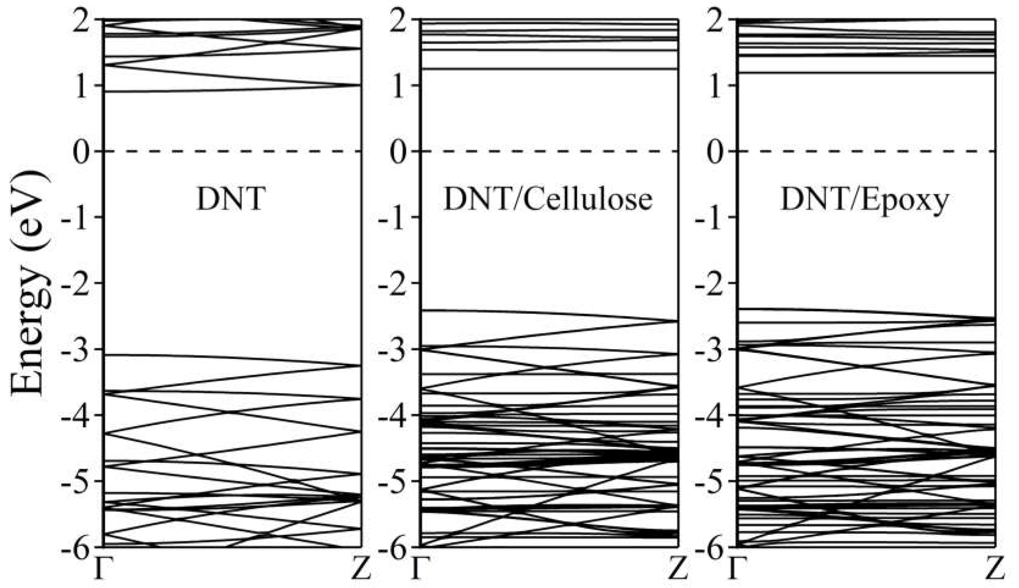
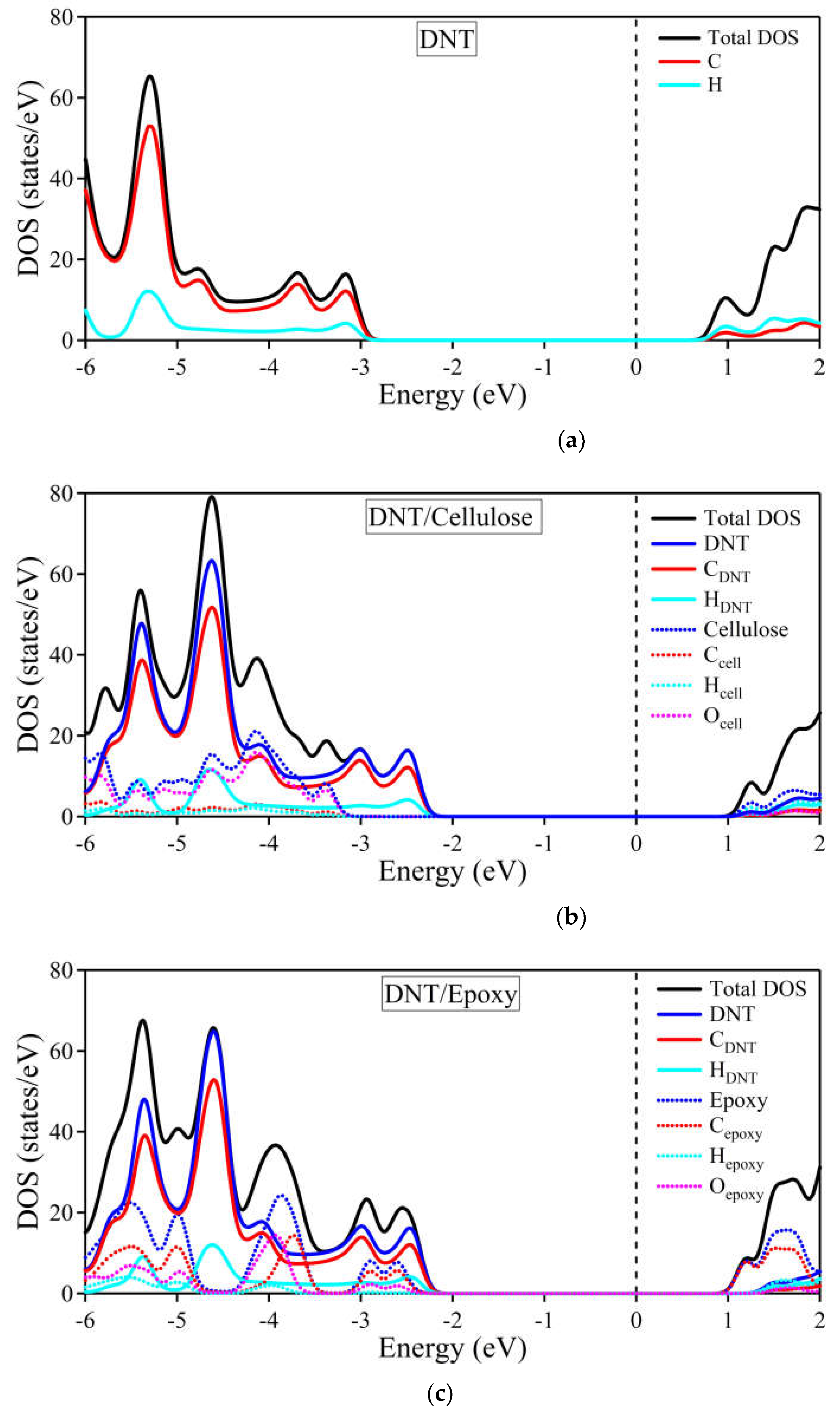
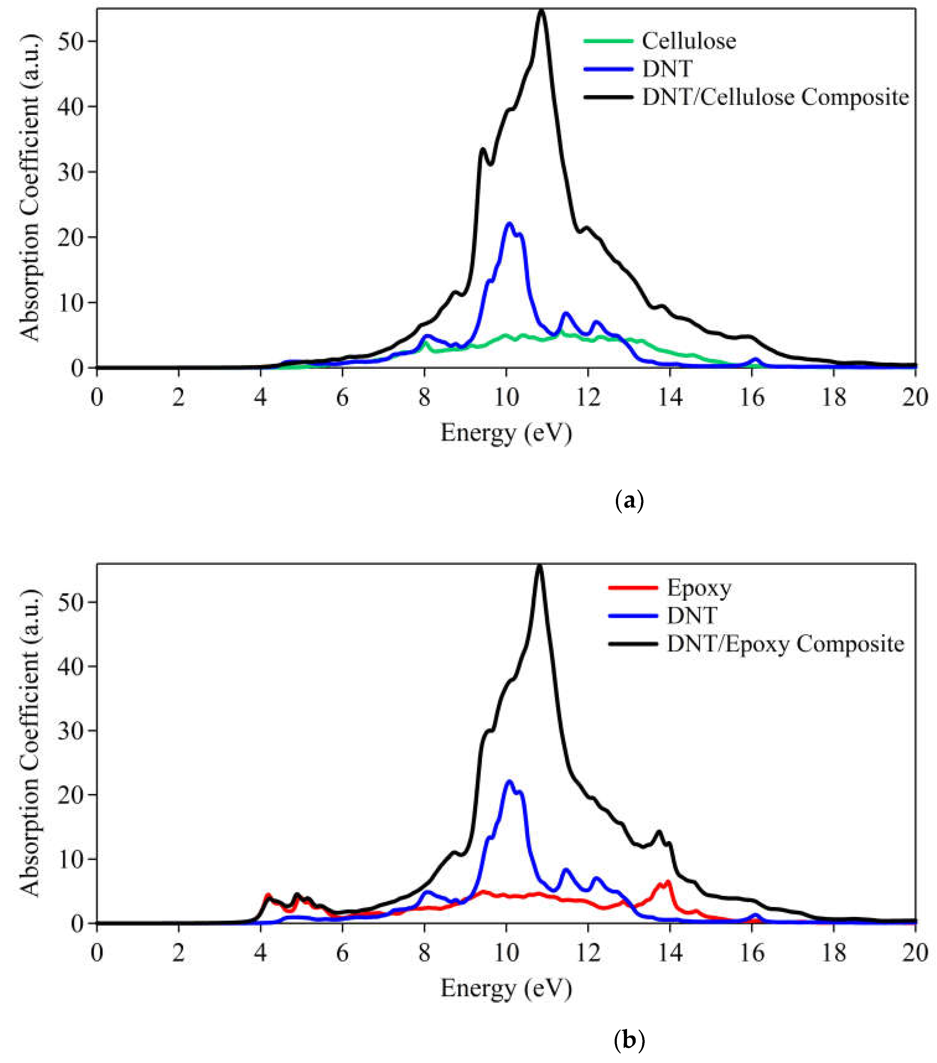
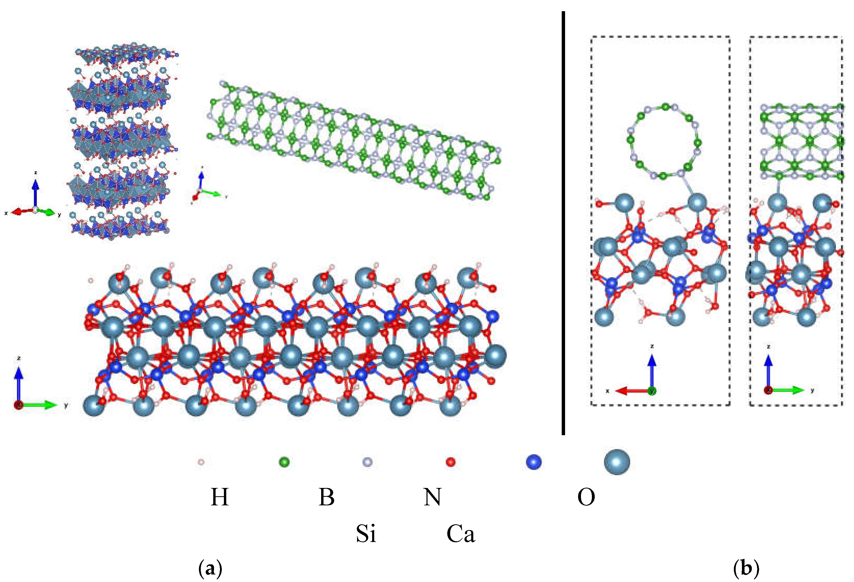
| System | (Å) | (eV) | (e) |
|---|---|---|---|
| DNT/cellulose – 1 | 3.67 | – 0.797 | – 0.008 |
| DNT/cellulose – 2 | 3.42 | – 0.730 | 0.004 |
| DNT/cellulose – 3 | 3.48 | – 0.726 | – 0.006 |
| System | (Å) | (eV) | |
|---|---|---|---|
| DNT/Epoxy – 1 | 3.56 | – 0.224 | – 0.003 |
| DNT/Epoxy – 2 | 3.64 | – 0.236 | – 0.019 |
| DNT/Epoxy – 3 | 3.60 | – 0.168 | 0.002 |
Disclaimer/Publisher’s Note: The statements, opinions and data contained in all publications are solely those of the individual author(s) and contributor(s) and not of MDPI and/or the editor(s). MDPI and/or the editor(s) disclaim responsibility for any injury to people or property resulting from any ideas, methods, instructions or products referred to in the content. |
© 2024 by the authors. Licensee MDPI, Basel, Switzerland. This article is an open access article distributed under the terms and conditions of the Creative Commons Attribution (CC BY) license (http://creativecommons.org/licenses/by/4.0/).


