Preprint
Concept Paper

Smart Shoe Tightening System for People with CP

This version is not peer-reviewed.

Submitted:

07 June 2024

Posted:

10 June 2024

You are already at the latest version

Abstract
Cerebral Palsy (CP) poses substantial challenges to individuals, affecting their physical capabilities and daily functioning, and necessitates tailored interventions to enhance their quality of life and independence. Hand functionality is often affected in more than 60% of individuals with CP; they (mostly children) may spend up to 2-3 hours tightening their shoes perfectly. This includes the tightening of laces, standing up to determine if it is sufficient, and having to repeat the process many times till desired throughout the day. This paper focuses on the development of such a system that will assist them in effectively reducing this time to an approximate maximum time of 10 minutes. In its proposed form, this would reduce the shoe-tying process and make it ~18 times faster. The system will allow the user to perform the process with one hand and be simple and reliable. This additional freedom, among utilization of other systems, could lead to a betterment in mental health regarding the desire to perform outdoor activities among individuals with CP
Keywords: 
Subject: 
Engineering  -   Bioengineering

II. Introduction

Cerebral Palsy (CP) is a congenital disorder affecting movement, muscle tone, and posture, primarily caused by abnormal brain development or injury either before birth or shortly after. Individuals with CP may experience a range of symptoms, including exaggerated reflexes, floppy or rigid limbs, and involuntary movements, which permanently impair the brain’s ability to control movement and maintain balance and posture [1].
CP is the most common developmental disability in childhood, impacting motor function, balance, and posture due to damage in the brain regions responsible for muscular control [1,2,3]. The severity of CP symptoms varies widely; some individuals might require special equipment to walk or need lifelong care, while others may have only minor motor difficulties. CP is usually diagnosed in early childhood and necessitates substantial care, significantly affecting a child’s independence and ability to develop essential life skills. Treatment focuses on fostering self-sufficiency and helping individuals gain the skills needed for independence and maturity [2].
The challenges associated with CP extend to performing basic tasks, which can be time-consuming and physically demanding. Activities such as getting out of bed, walking, driving, cooking, cleaning, and even tying shoelaces can be significantly prolonged. This not only imposes physical limitations but also causes considerable mental strain over time. For example, adjusting shoe tightness to achieve a proper fit can take several hours, illustrating the extensive effort required for simple routine activities. Figure 1 illustrates key points on the foot where an individual with CP might want pressure; as such, the shoe-tying process grows in complexity.
This project is designed to reduce the time it takes an individual to perform this basic function. The long-term goal of this project is to reduce the time for the shoe-tightening process and allow individuals with CP to become more independent.
Requirements for the system are as follows:
  • Must allow individuals with only one arm functionality to be able to tighten their shoes.
  • Must be lightweight.
  • Must not apply too much counter torque on the arms of the individual.
  • Must be usable on any shoe.
The system must reduce the time of the shoe-tightening process to a maximum of 10 Minutes. In its proposed form, the system would reduce the shoe-tying process and make it 18 times faster.
Testing of the device can be simulated by any individual by performing the task with only one arm. This captures the capability of CP individuals to utilize this system. However, testing specifically on individuals with CP will provide a more accurate review of the system.

III. Related Work

The fashion industry has long been intrigued by the concept of self-tying shoes, viewing them as a potential future trend. Consequently, numerous designs have emerged that eliminate the need for traditional lacing. The key features and the limitations of each design are discussed below:
Design 1—Lace Pull System
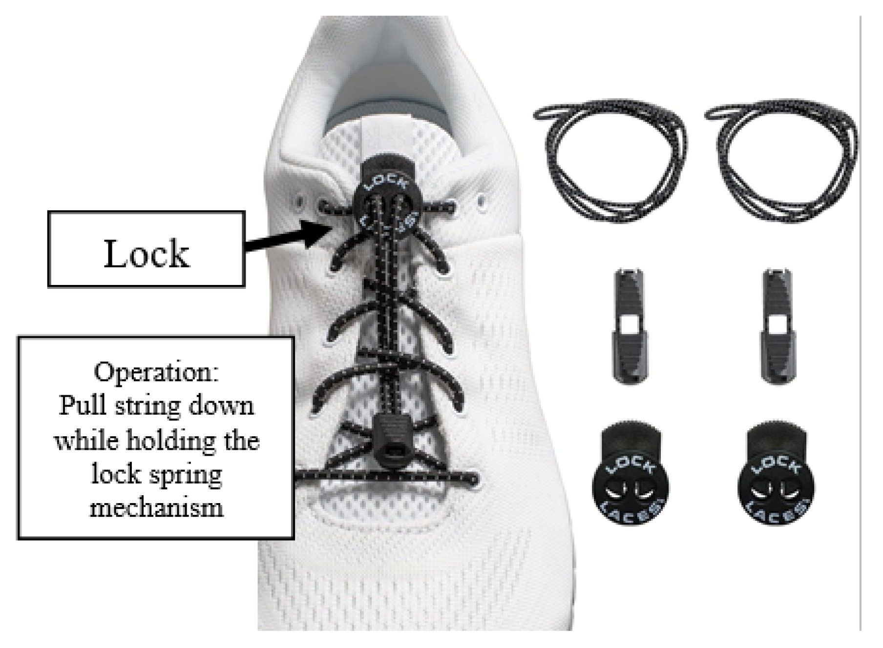
The Lace Pull System, shown in Figure 2, is efficient and simple. Threaded through like a regular shoelace, but instead of a knot, it utilizes a spring lock.
The advantages and disadvantages of this design are as follows:
Advantages:
  • Simple to install.
    o
    Can be installed on most shoes.
  • Simple to operate.
  • Cheap and extremely cost-effective.
Disadvantages:
  • Requires two hands to operate.
  • Doesn’t provide sufficient tightness.
    o
    Doesn’t provide tightness at the necessary locations.
    o
    Spring lock tightness depreciates over time.
Design 2—No lace System
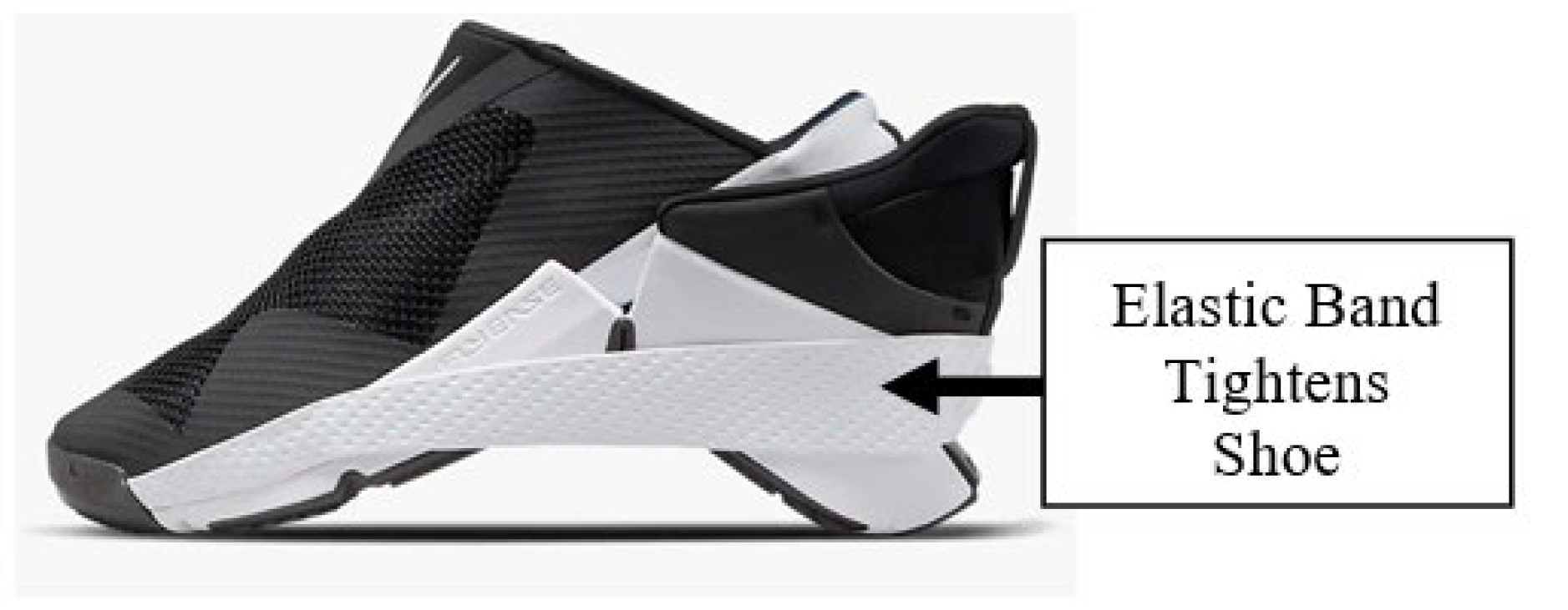
Shoes without laces, shown in Figure 3, have been a very common design choice for much of the fashion industry in the recent past.
The advantages and disadvantages of this design are as follows:
Advantages:
  • No shoelace is required to utilize the shoe.
  • Simple to operate and wear.
Disadvantages:
  • Requires the purchase of a new shoe.
    o
    Nike shoes (shown in Figure 3) cost ~125$.
  • Does not provide the tightness required by individuals with CP.
    o
    Figure 1 shows the location where tightness is required on a shoe for an individual with CP.
  • Over time, the tightness of the shoes will be lost as they are tight-fitted shoes that will expand over time.
  • If true tightness is required, a customized shoe will need to be created for the individual.
    o
    This will increase the cost of manufacturing dramatically.
Design 3—Self Lacing (Motorized)
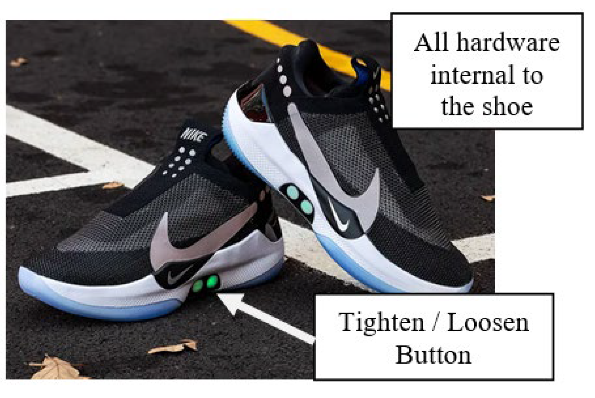
Self-lacing motorized shoes are looked at as the future of the shoe industry. Many companies are racing to produce the best and cheapest model. The below Figure 4 is Nike’s newest take on the idea [5,6,7,8].
Advantages:
  • Easy to operate.
    o
    The motorized system does not require anything but the press of a button to operate.
Disadvantages:
  • Expensive
    o
    Requires the purchase of a new shoe, estimated at around 450$.
  • Heavy
    o
    With a built-in motor and battery, the shoe is much heavier than a regular shoe.
  • Battery operated
    o
    There is no way to operate the current shoe if the battery dies.
    o
    equires better battery technology to be efficient.
  • Overly complex
    o
    Simple devices (shoes) became much more complex with this design.
    o
    Technology can bug or damage.
    o
    No easy way to take off shoes once an issue occurs.
Design 4—Hand Tightened Lacing System
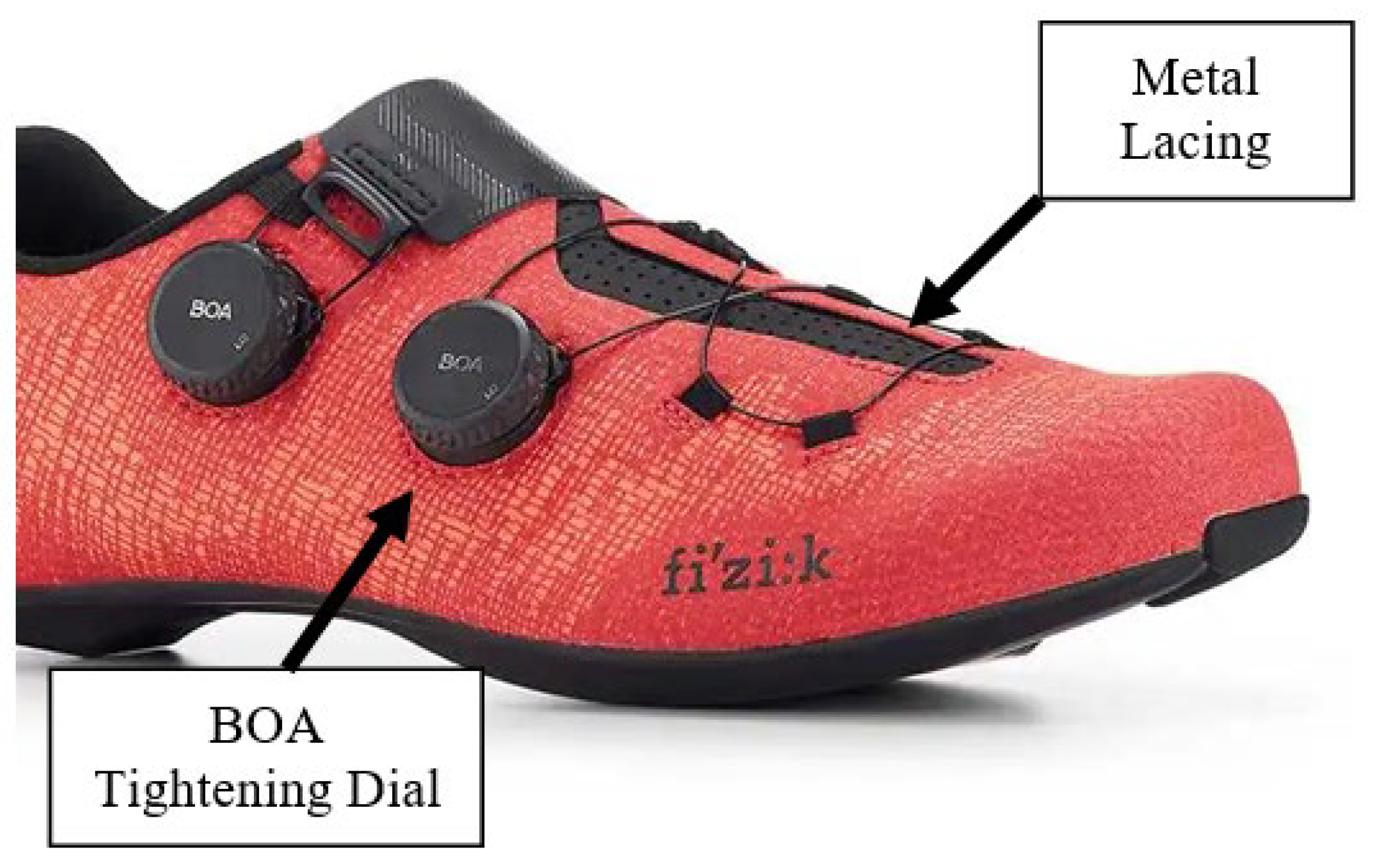
BOA Technologies developed the BOA Li2 dial. The BOA dial system is utilized in multiple ways, most commonly on sports shoes, such as bike racing shoes, snowboard shoes, and a few medical devices, as shown in Figure 5. This allows the user to spin a dial, which will tighten the shoes as necessary.
Advantages:
  • Simple
    o
    Spin a dial to tighten the shoe.
    o
    Pull vertically will loosen the system.
  • Reasonable Pricing
    o
    BOA system will cost between 40 and 50$
  • Can be operated with one hand.
Disadvantages:
  • BOA system shoes are not exactly manufactured for people with CP. As such, the individual will be required to install the BOA system on the desired shoe.
    o
    No simple way to install BOA onto shoes.
  • After a certain amount of tightness, the counter torque produced when spinning the dial is too great for some individuals with CP.
Summary of previous designs
The designs mentioned previously are suitable for particular circumstances. It is crucial for the user to grasp the intended purpose to select the most suitable option. However, none of these designs are suitable for individuals with CP. Since this project’s target is individuals with CP, the following constraints must be met:
  • Design 1 lacks the required tightening capability in crucial areas.
  • Similar to Design 1, Design 2 also falls short of providing sufficient tightening.
  • Design 3’s additional technology adds considerable weight, making it challenging for the individual to walk.
  • Design 4 is difficult to operate due to the excessive torque needed for tightening.
To meet the needs of the individuals, the solution must integrate the various designs discussed previously.

IV. Design Choices

Individuals with CP have greater issues that need to be accounted for when designing a system. The new system must meet the following requirements to operate correctly for individuals with CP:
  • Should enable individuals with single-arm functionality to tighten shoes effectively.
  • Should be lightweight.
  • Should avoid exerting excessive counter-torque on the individual’s arms.
  • Should be compatible with any type of shoe.
  • The system must not interfere with or prevent the individual from any foot movement.
A shoe-tying mechanism integrated directly into the shoe would result in excessive bulk and weight, rendering it impractical. Therefore, the system must consist of two components: a shoe-tightening mechanism and a separate tool for tightening.
Description of the design for each component of the system is described below:

A. Shoe Tightening Mechanism

After evaluating the strengths and weaknesses of previous systems, it was determined that a dial-style mechanism integrated into the shoe offers the most functionality. Dial systems are proven to be effective and reliable, and they are widely used in various sports where durability and performance are crucial.
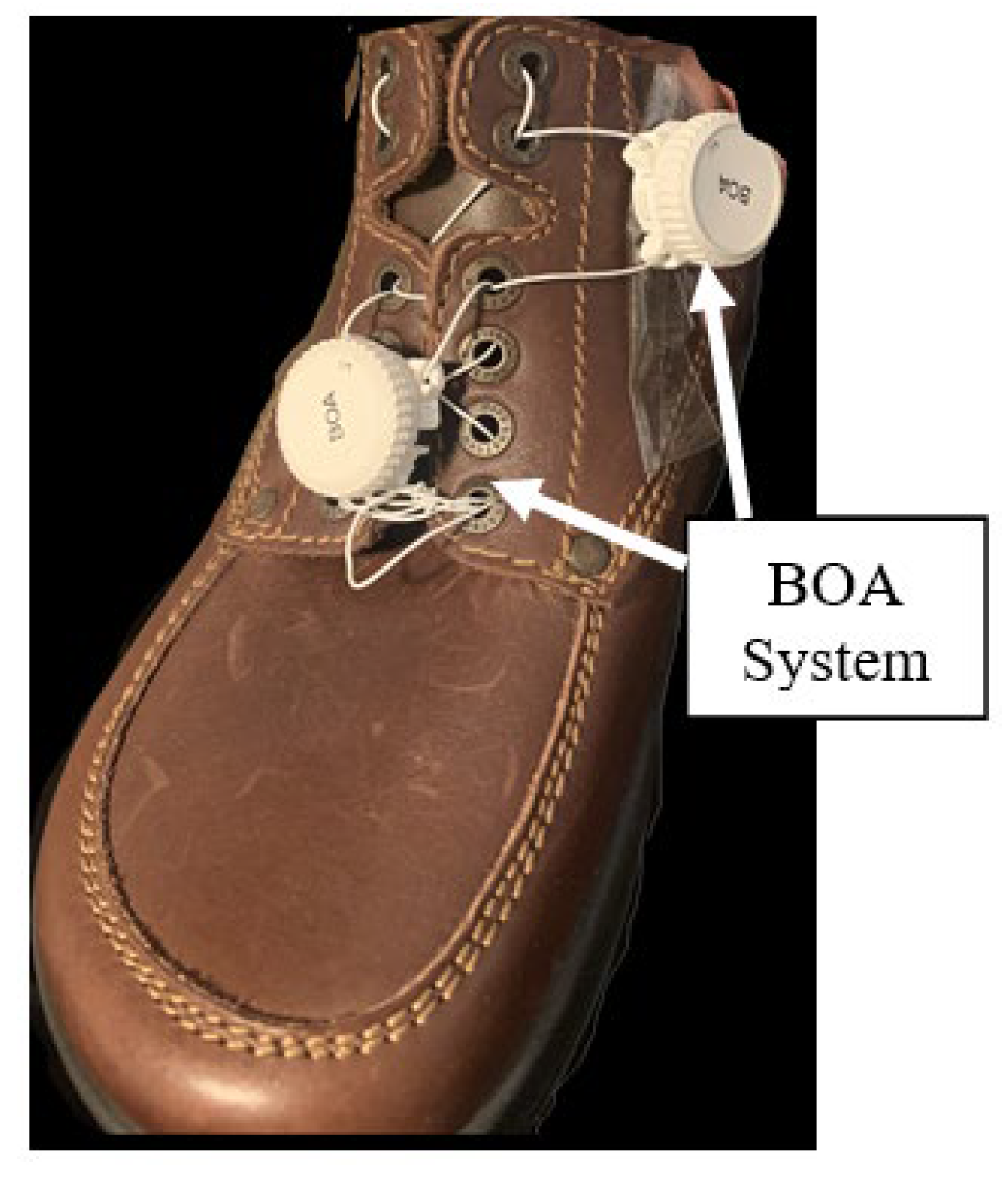
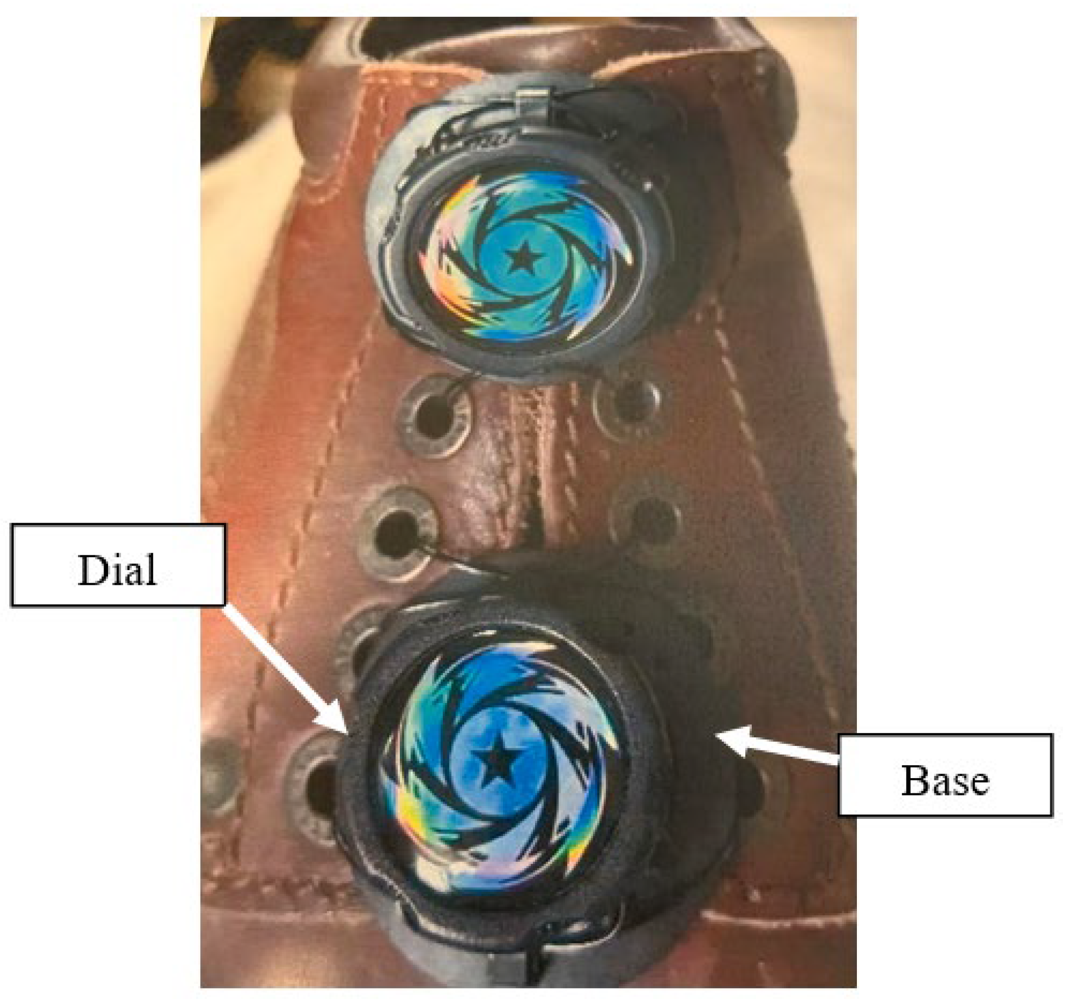
The initial phase of designing this system involved testing the functionality of the dial mechanism first. A cost-effective dial was purchased and installed on a shoe (see Figure 6).
Two dials were used to provide sufficient tightening capability to meet the need for tightness near the toes of the individual. The dials were deemed to be slightly uncomfortable. The base of the cost-effective dial is large, causing an uncomfortable feeling when the foot needs to bend while walking.
The functional test proved highly cost-effective and informative. At just $1.5, it yielded valuable insights into various lacing methods and the reliability of dial mechanisms.
Based on the findings of the initial test, more confidence was built into investing in the BOA system, which typically retails for around $40.
Figure 7. Dial System Version 2.
Preprints 108636 g007
The BOA system shares large similarities with the inexpensive dial; however, it boasts significantly greater strength and a well-established track record, demonstrating its reliability. The BOA cables are metallic cords that are proven to withstand substantially large loads.
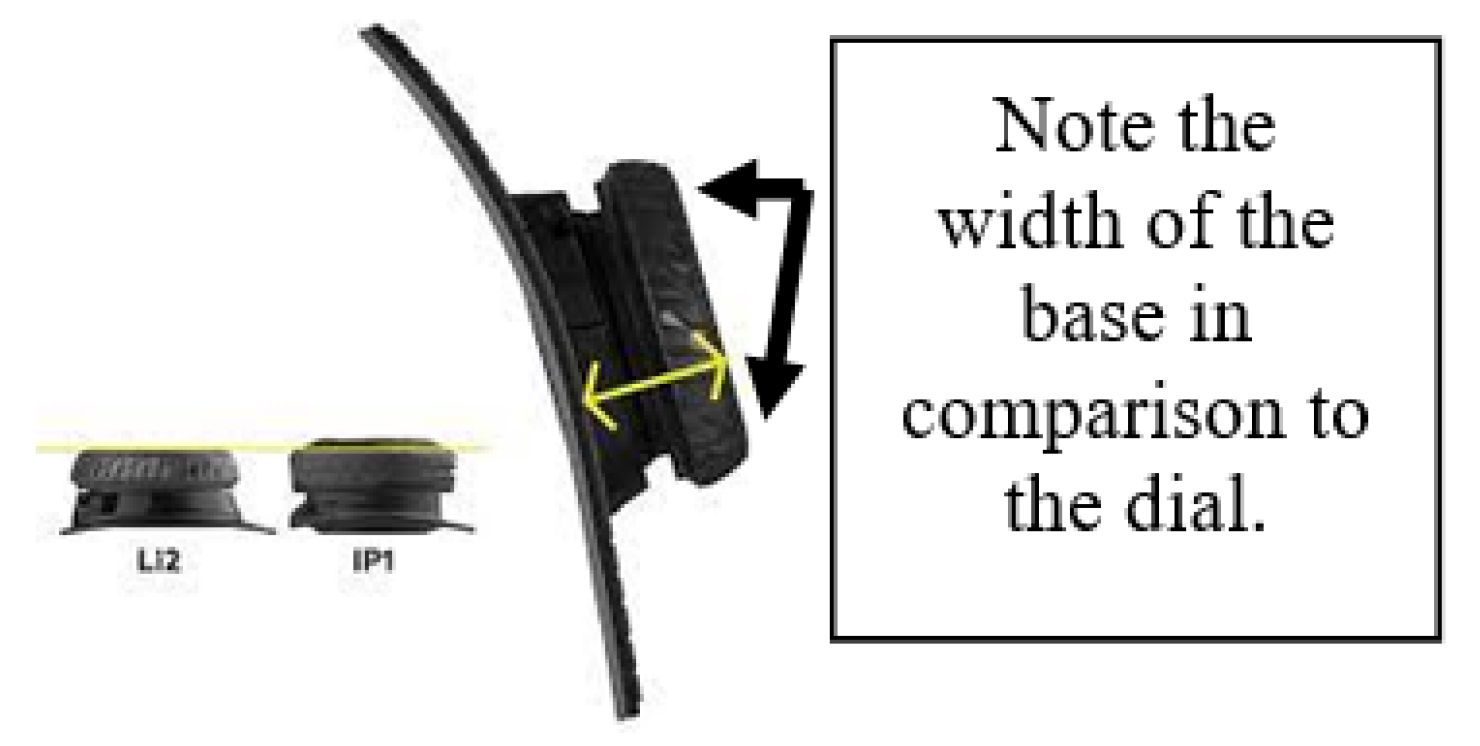
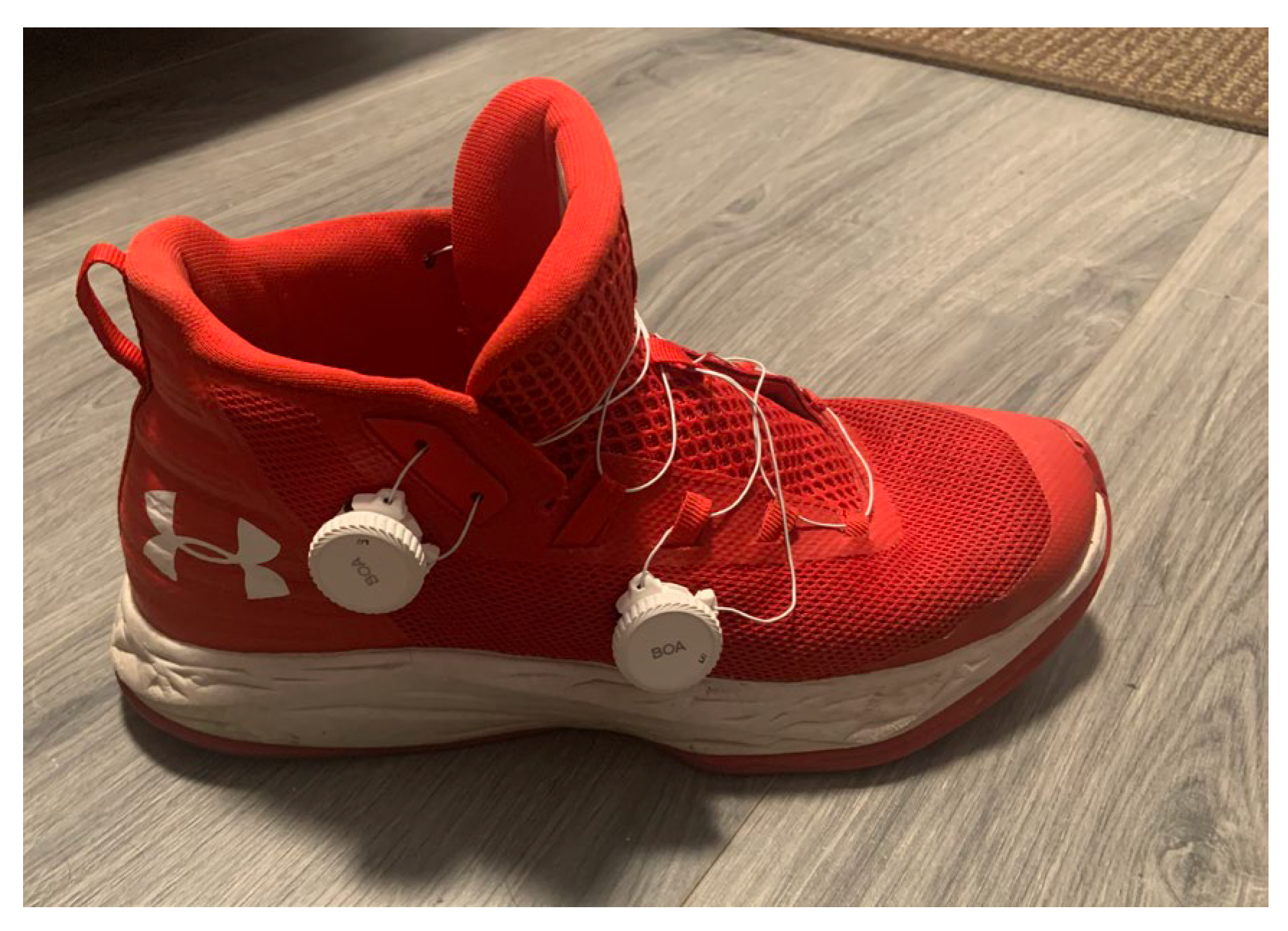
The second test provided an opportunity to evaluate more than just the reliability of the BOA system. Unlike the inexpensive dial, the BOA system does not feature a bulky base (as depicted in Figure 8), thus eliminating concerns regarding the base affecting comfort while walking.
As shown in Figure 7, the BOA system was tested in two configurations: one with the BOA positioned over the laces and another placed at the side of the shoe. It is important to note that both configurations were effective in operating; however, the placement of the BOA on top of the shoelaces and shoe tongue prevented the free movement of the shoe tongue, making the shoe harder to wear. Therefore, the perfect location to install both BOA systems is on the side of the shoe.

B. Shoe Tightening Tool

Given that the BOA system requires torque in order to tighten the shoe, a mechanism must be designed to allow individuals with CP to tighten it comfortably and easily. This can either be a motorized system or a manual one-handed tightening system.
Two styles of tightening were designed and evaluated as described below:

1) Motorized System

The motorized system will function similarly to a cordless drill but with the specific task of tightening the BOA system without causing excessive torque or damaging the shoe.
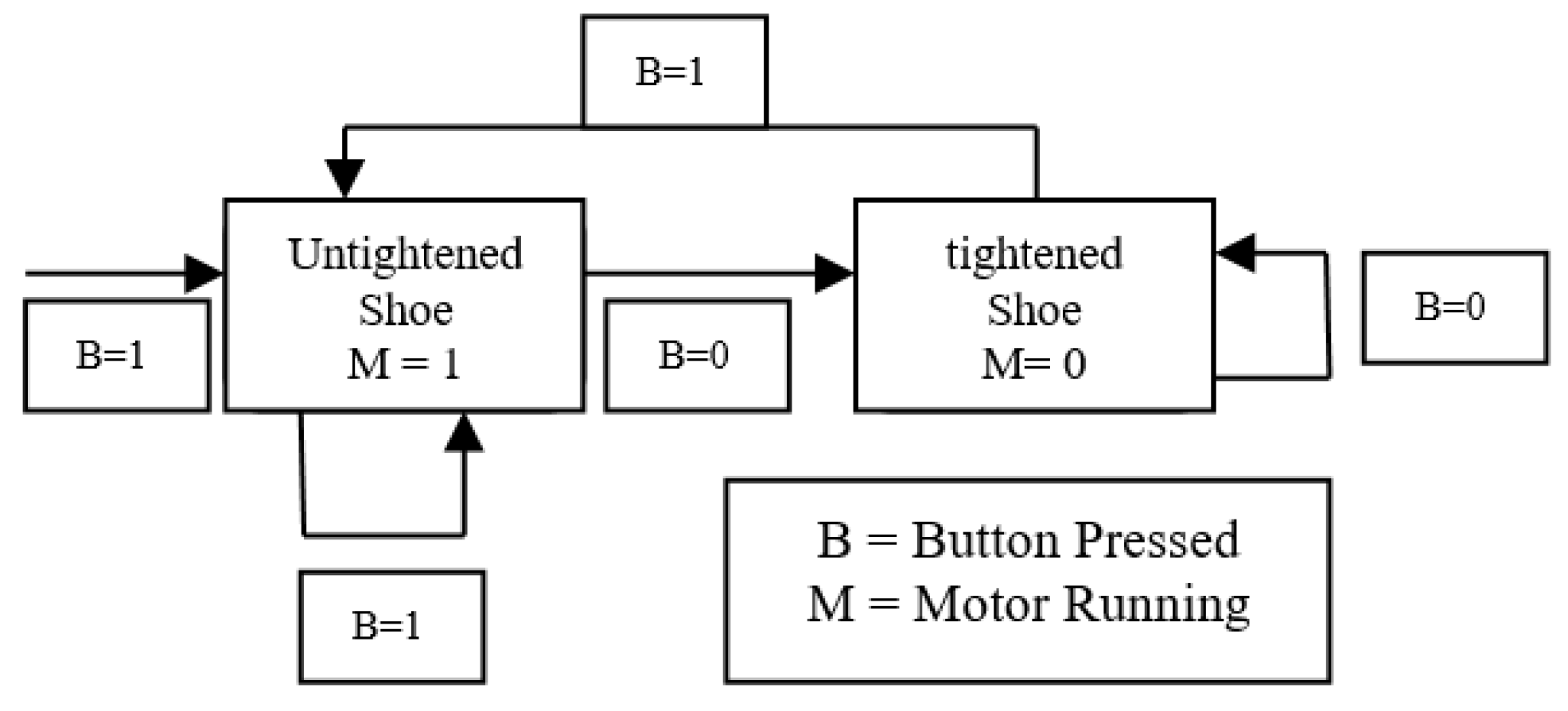
The motorized system operates as follows:
The button will operate as follows:
  • The initial press will activate the motor.
    o
    If the button is held, the motor will continue operating.
  • Once un-pressed, the motor will stop tightening.
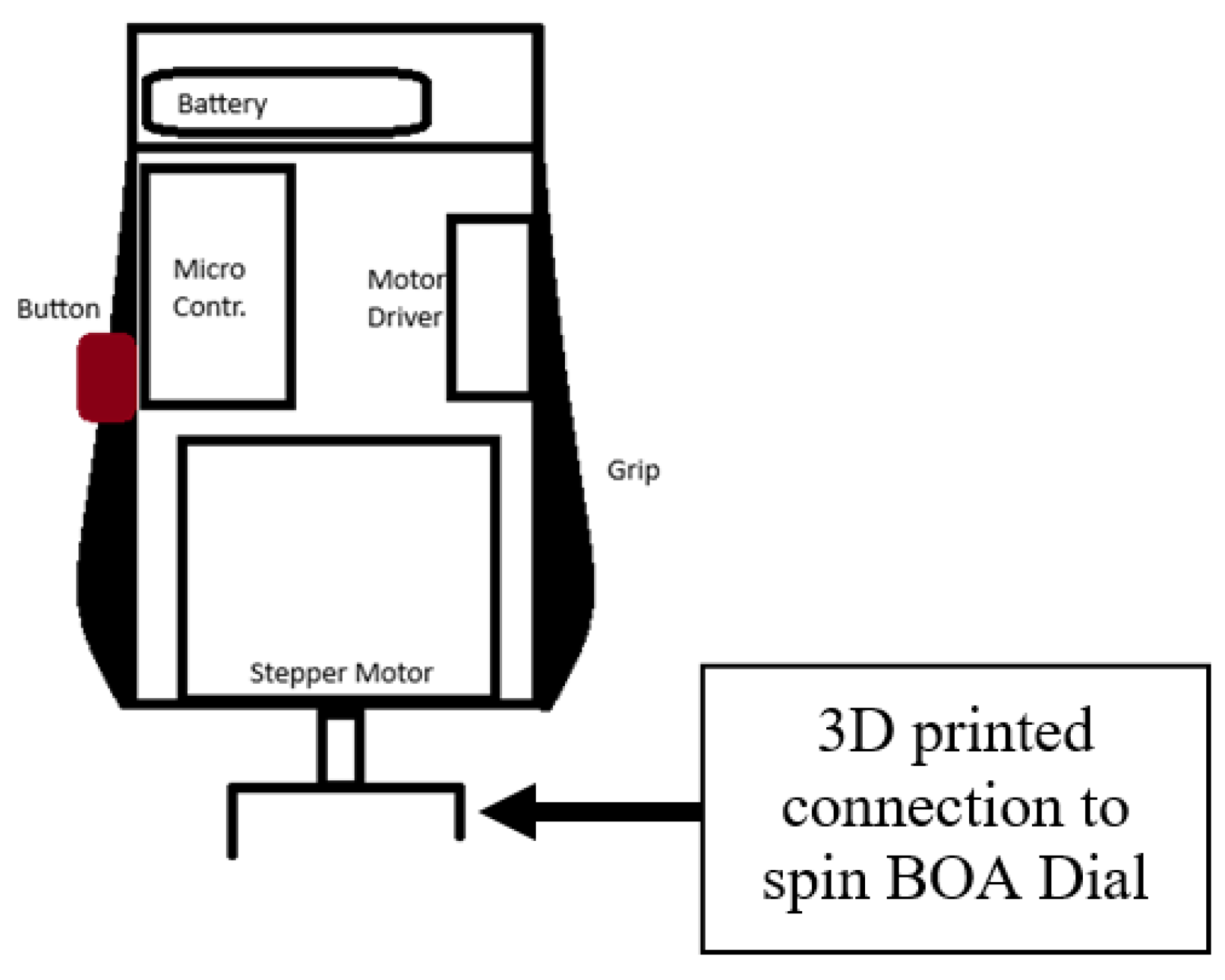
This motorized system will need to include the following components to operate effectively.
  • Battery
  • Microcontroller
  • Button
  • Stepper Motor
  • Motor Driver
This system will most likely be designed as shown below in Figure 10. To allow for one-handed operation.

2) Manual Handheld System

Although the BOA system can exert significant counter-torque on the individual’s arm once a certain tightness is reached, a manual system can serve as a ‘cheater bar’, reducing the experienced counter-torque.
This system will require the following actions:
  • Engage the BOA system.
  • Torque as necessary.
  • Disengage the BOA system.
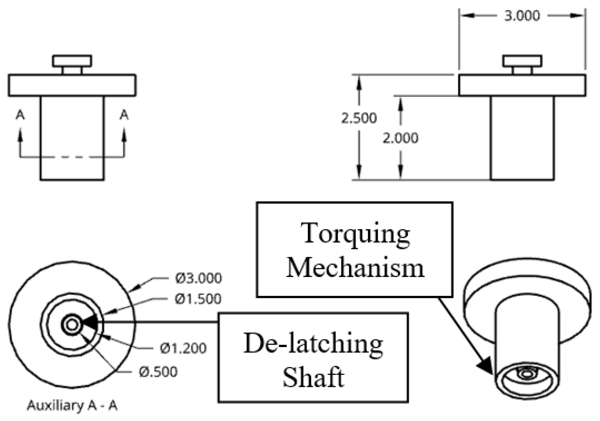
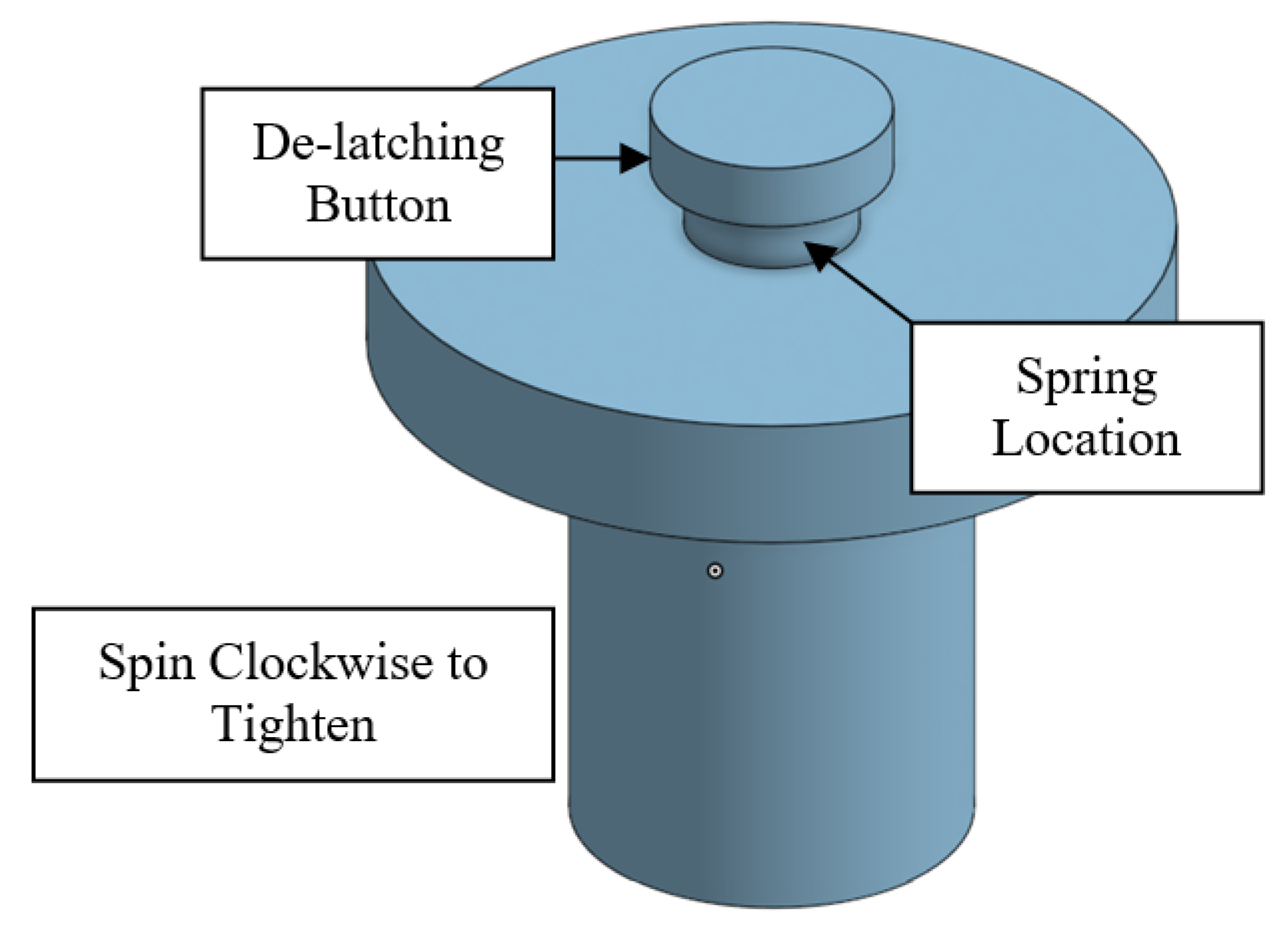
A preliminary design was created to perform the specified above. This design consists of the following:
  • Round handle
    o
    The round handle allows the user to twist the system easily while keeping a downward vertical force on the BOA system.
  • Latching system
    o
    The system will engage once it is pressed down on the BOA system.
    o
    The system will disengage with the disengage spring-loaded button. This spring-loaded button is attached to the de-latching shaft shown in Figure 11 and Figure 12.

V. Final Design

As previously outlined, the overall design integrates a mechanism for tightening the shoe along with a distinct tool for tightening the BOA system. Details regarding the decisions made for the final design are elaborated below:
Shoe Tightening Mechanism
The placement of the BOA tightening dials underwent a trial-and-error process to determine the optimal positioning.
  • Both dials on the laces (Figure 6)
    o
    Uncomfortable
    The base of the dials interfered with the movement of the foot.
    o
    Hard to wear
    Installing the dials on the tongue of the shoe prevents the tongue’s movement and hinders the process of wearing the shoe.
  • One dial on the tongue, the other on the side (Figure 7)
    o
    As per the previous description, installing the dials on the tongue of the shoe prevented the tongue’s movement and hindered the process of wearing the shoe.
As such, the BOA system was installed using robust threading and stitched onto the sides of the shoes, as illustrated in Figure 13. The installation of the BOA system on the side of the shoe using thread allowed for precise adjustments and enhanced comfort, providing users with a seamless experience during wear.
BOA Tightening Tool
The manual handheld design depicted in Figure 12 was selected for further development due to the following reasons:
  • Simplicity
  • Weight
  • Safety
Considering the possibility for children to use this system, safety became a crucial aspect of the design. Children tend to misuse objects, and motor-operated equipment can pose significant dangers in their hands. Therefore, opting for a manual tool over a powered one reduces complexity and potential hazards for children.
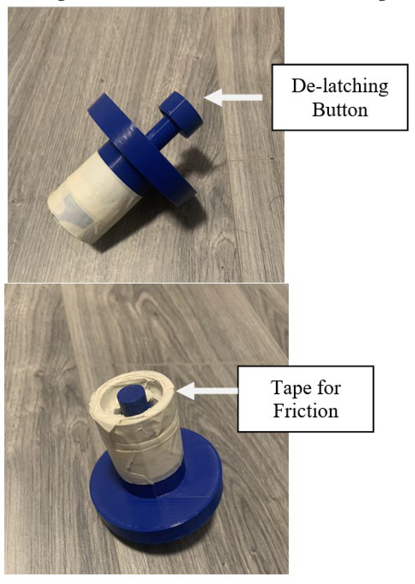
A 3D-printed model of this design was created and is shown in Figure 14.
The initial iteration of the torquing tool is a 3D printed model, which effectively fulfills all its functions at a remarkably affordable price.
Minor modifications were needed for the developed design. The 3D-printed model exhibited a sleek, almost frictionless surface, resulting in a less-than-optimal connection between the handheld tool and the BOA system. As such, painter tape was added to increase the friction of the surface between the torquing mechanism (Figure 11) and the BOA torquing system.

VI. Testing

Testing of the system is possible with the fully functional Manual Torquing tool and a shoe with two BOA torquing dials. To imitate a person with CP, testing met the following requirements:
  • Only utilize one hand
  • Only tighten with the torquing tool
Testing followed the following order:
  • Wear the Shoe
  • Align the shoe tongue as desired
  • Install the torquing tool on the first BOA dial
  • Torque as necessary, de-latch when satisfactory
  • Repeat steps 3 and 4 for the other BOA dial
  • Loosen the torque dials
  • Take off shoe
The test was performed five times, and the test results were highly encouraging, with the system performing as intended. The inclusion of painter’s tape for added friction proved essential, enabling the torquing tool to execute its function effectively.
The system was able to:
  • Be operated with on-hand
  • Tighten the shoe to the comfort desired
  • The process was performed in under 1 minute
While the results of the tests were positive, we lack data from an individual with CP. While beneficial, it is not required. The test was completed with the use of a single hand to simulate the CP individual. Additionally, no excessive counter torque was experienced due to the torquing tool, making the device usable by anyone.

VII. Discussion and Conclusion

The Shoe Tightening System designed for individuals with CP presents a promising solution to alleviate the challenges faced during the shoe-tightening process. The system integrates a shoe-tightening mechanism with a handheld tool, aiming to reduce the time required for this essential task and enhance the independence of individuals with CP.
The shoe-tightening mechanism incorporates a BOA dial system strategically positioned on the sides of the shoe to ensure optimal comfort and functionality. Meanwhile, the handheld tool provides a manual option for tightening, prioritizing simplicity, safety, and ease of use.
Testing of the system has yielded positive results, demonstrating its effectiveness in tightening shoes within a short timeframe and without causing discomfort or excessive torque.
While the system shows great promise, future iterations could benefit from additional testing with individuals with CP to gather more specific feedback and ensure its suitability for their needs.
Refinements in design and materials could enhance durability, comfort, and user experience. Overall, the Shoe Tightening System represents a significant advancement in addressing the unique challenges faced by individuals with CP in performing everyday tasks, ultimately contributing to improved independence and quality of life.
The following improvement will be added to the next iteration of the system:
  • Rougher material surfaces at the connection point.
  • Replace the circular gripping shape to increase hand comfortability.
Further research is required in the following areas:
  • Motorized system
    o
    This system would allow everyone to utilize it, including personnel with no hand usage.
    o
    The system must include capabilities for children to utilize without any safety risks.
  • Other methods for attaching the BOA system
    o
    The current BOA system requires that the torque dial be stitched onto the shoe. This could limit the ability of some individuals to utilize this system. Additional methods are required for attaching are required.

References

  1. Centers for Disease Control and Prevention. “Facts about Cerebral Palsy.” Centers for Disease Control and Prevention, National Center on Birth Defects and Developmental Disabilities, 1 Dec. 2021, www.cdc.gov/ncbddd/cp/facts.html.
  2. Kim, Ju Yong, et al. “Long-term Follow-up of Botulinum Toxin-A Treatment for Lower Limb Spasticity in Children with Cerebral Palsy: A Prospective Study.” Annals of Rehabilitation Medicine, vol. 44, no. 1, 2020, pp. 31–40. [CrossRef]
  3. Adie, Sam, et al. “Robotics and virtual reality for upper limb training in patients with chronic stroke: A protocol for a randomized controlled trial.” Journal of Rehabilitation and Assistive Technologies Engineering, vol. 6, 2019, pp. 1–7. [CrossRef]
  4. Barker, Scott M., et al. “Unilateral versus Bilateral Casting for Clubfoot: A Systematic Review and Meta-Analysis.” Journal of Pediatric Orthopedics, vol. 39, no. 2, 2019, pp. e143-e149. [CrossRef]
  5. Nike Innovate C.V. “Motorized Footwear System.” US Patent US8769844B2, filed 7 June 2012, issued 8 July 2014.
  6. Pukall, Caroline. “DIY Back to the Future Shoes Powered by Arduino.” Make:, 4 Nov. 2014, makezine.com/article/technology/arduino/diy-back-to-the-future-shoes-powe.
  7. Ren, Y., et al. “The Impact of Self-Lacing Technology on Foot Containment during Dynamic Cutting.” Journal of Sports Sciences, vol.39,no.1,2021, pp. 107-113. [CrossRef]
  8. Ren, Y., et al. “Motorized Self-Lacing Technology Reduces Foot-Shoe Motion in Basketball Shoes during Dynamic Cutting Tasks.” Journal of Applied Biomechanics, vol. 36, no. 4, 2020, pp. 297-302. [CrossRef]
  9. “LI2 Dial Platforms.” BOA Fit System, www.boafit.com/en-us/innovation/dial-platforms/li2.
  10. “Nike Go FlyEase: Easy On, Easy Off Shoes.” Nike.
  11. “Nike Adapt BB Black/Pure Platinum - US 14.” StockX.
  12. “Lock Laces Elastic No Tie Shoelaces (Pack of 2).” Amazon, www.amazon.com/Lock-Laces-Elastic-Shoe-Pack/dp/B07JLXXYYP.
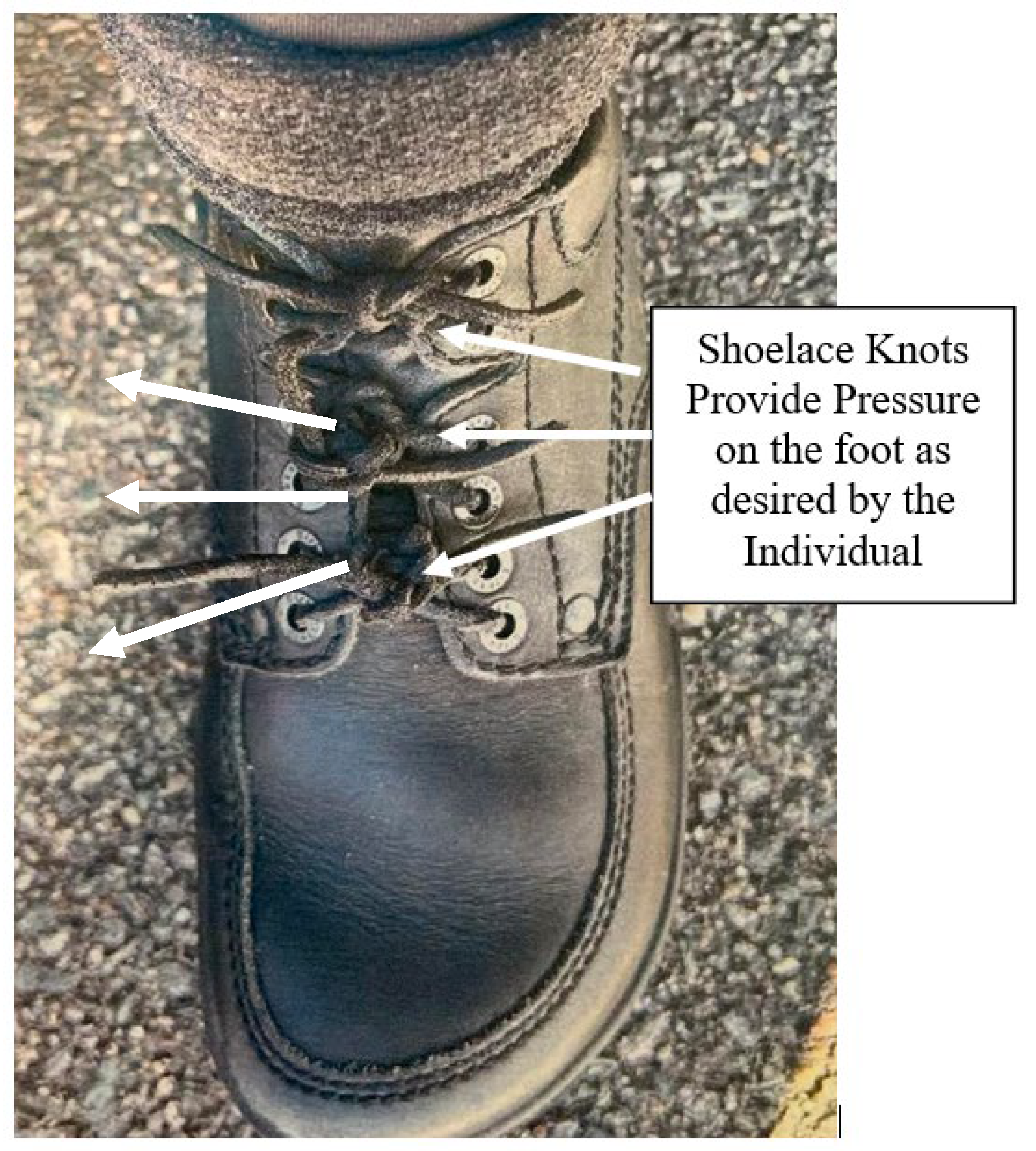
Figure 1. A shoe for an individual with CP.
Preprints 108636 g001
Figure 2. Lace Pull System [12].
Preprints 108636 g002
Figure 3. No Lace Shoe [10].
Preprints 108636 g003
Figure 4. Motorized Tying Shoes [11].
Preprints 108636 g004
Figure 5. Hand Tightened BOA Lacing System [9].
Preprints 108636 g005
Figure 6. Dial System Version 1.
Preprints 108636 g006
Figure 8. BOA System Design [9].
Preprints 108636 g008
Figure 9. Motorized System Block Diagram.
Preprints 108636 g009
Figure 10. Motorized System Low-Level Design.
Preprints 108636 g010
Figure 11. Manual Handheld Tightening System.
Preprints 108636 g011
Figure 12. Manual Handheld Tightening System 3D.
Preprints 108636 g012
Figure 13. Final Installation of BOA System.
Preprints 108636 g013
Figure 14. Handheld Design 1st Prototype.
Preprints 108636 g014
Disclaimer/Publisher’s Note: The statements, opinions and data contained in all publications are solely those of the individual author(s) and contributor(s) and not of MDPI and/or the editor(s). MDPI and/or the editor(s) disclaim responsibility for any injury to people or property resulting from any ideas, methods, instructions or products referred to in the content.
Copyright: This open access article is published under a Creative Commons CC BY 4.0 license, which permit the free download, distribution, and reuse, provided that the author and preprint are cited in any reuse.
Alerts
Prerpints.org logo

Preprints.org is a free preprint server supported by MDPI in Basel, Switzerland.

Subscribe

© 2025 MDPI (Basel, Switzerland) unless otherwise stated