Submitted:
07 June 2024
Posted:
11 June 2024
You are already at the latest version
Abstract
Keywords:
1. Introduction
2. Analytical Pull-Out Model for Inclined Hooked-End Fibre
2.1. Fibre Failure Criteria
2.1.1. Transverse Isotropy
2.1.2. Upper and Lower Bounds
2.1.3. Experimental Data
(cos2θ + 4 sin4θ/cos2θ + 4sin2θ ) = (σ1f /σ0°)2
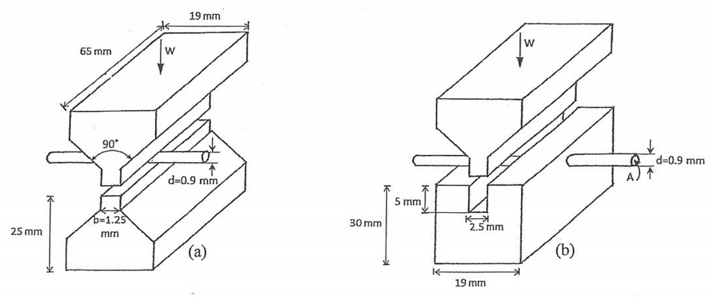
2.2. Fibre Strength Tests
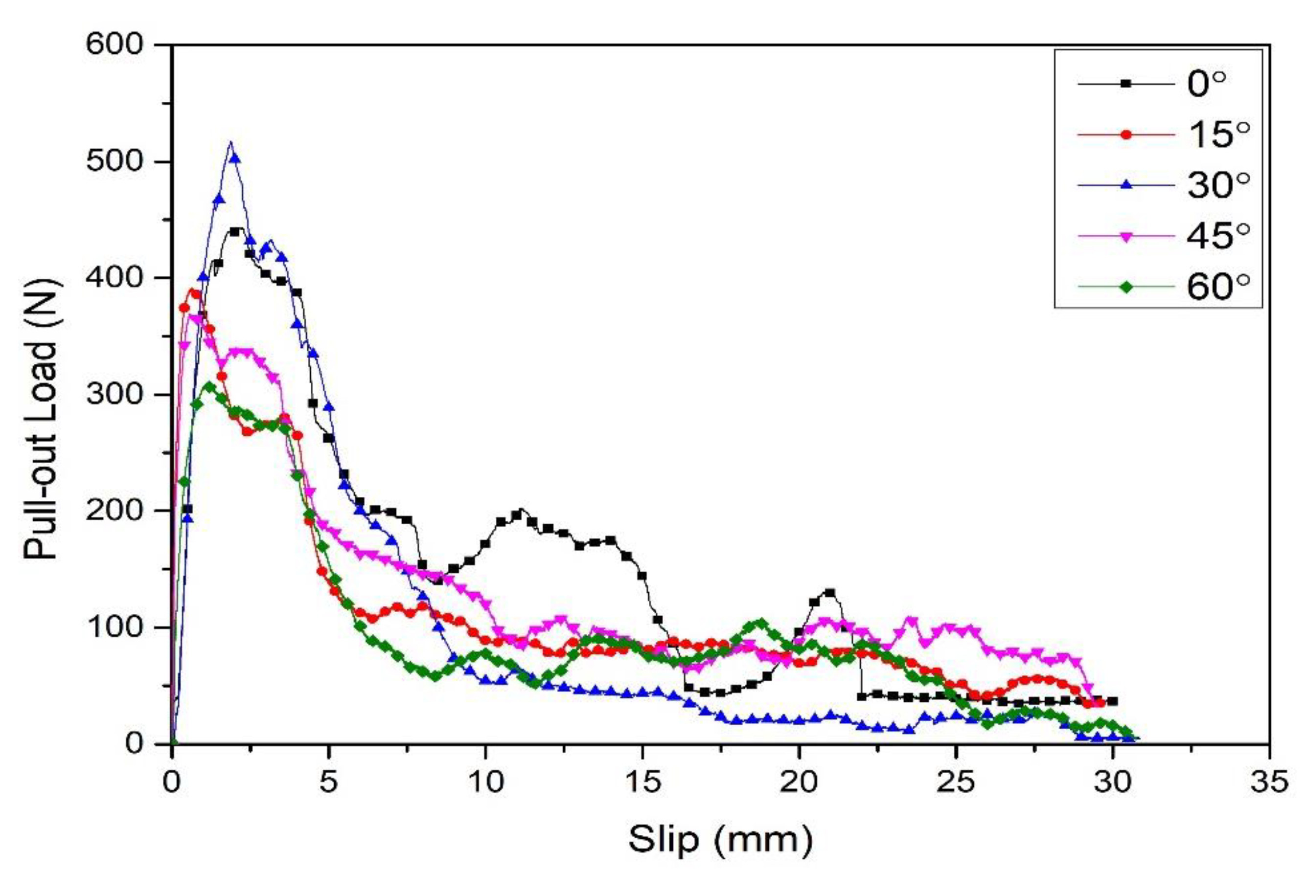
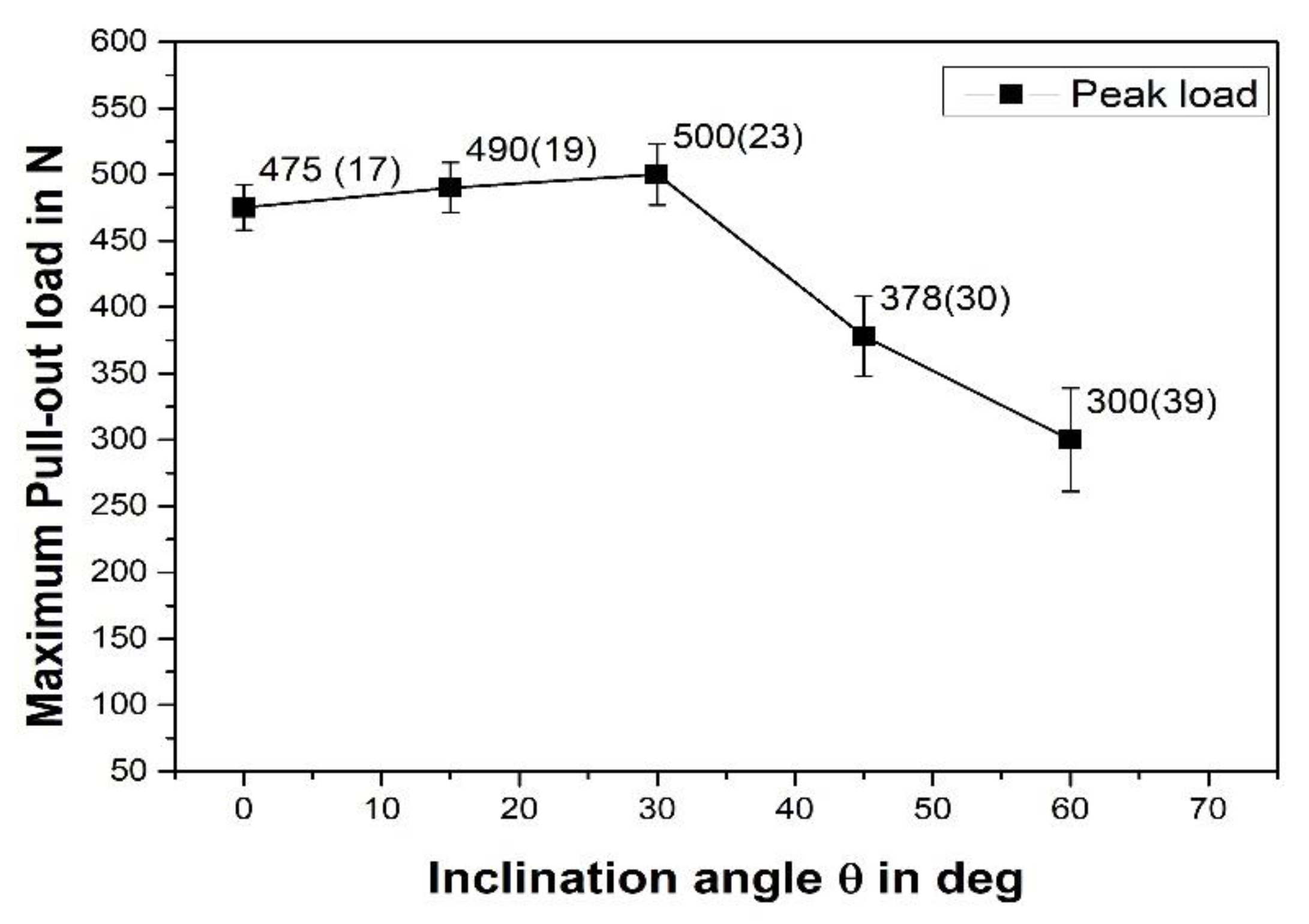
3. Pull-Out Tests of Inclined Fibres
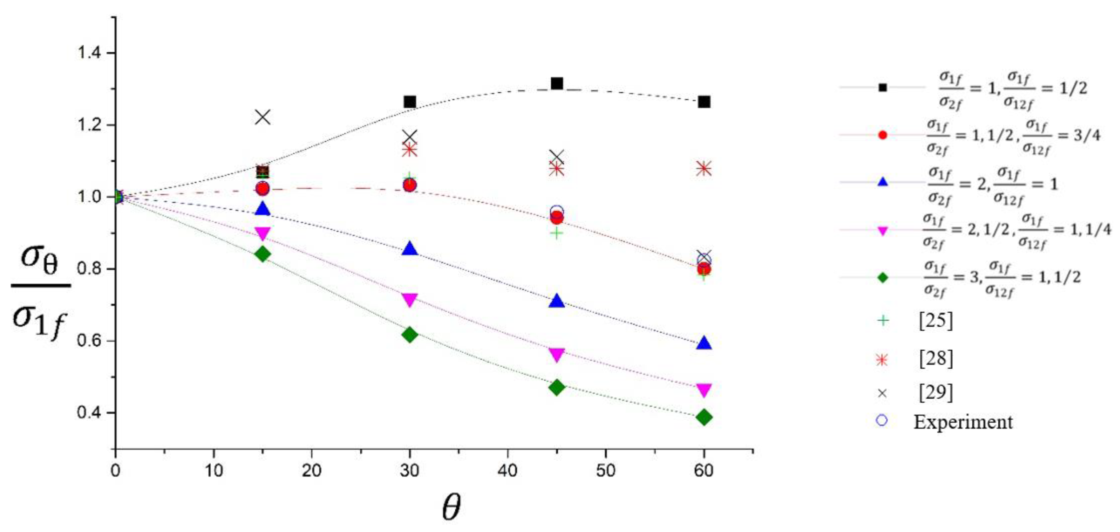
4. Bounding Model Refinements
5. Conclusions
References
- Wang, Y.; Hao, Y.; Hao, H.; Huang, X. An efficient method to derive statistical mechanical properties of concrete reinforced with spiral-shaped steel fibres in dynamic tension. Constr Build Mater 2016, 124, 732–745. [Google Scholar] [CrossRef]
- Zīle, E.; Zīle, O. Effect of the fiber geometry on the pullout response of mechanically deformed steel fibers. Cem Concr Res 2013, 44, 18–24. [Google Scholar] [CrossRef]
- Tai, Y.; El-Tawil, S. High loading-rate pullout behavior of inclined deformed steel fibers embedded in ultra-high performance concrete. Constr Build Mater 2017, 148, 204–218. [Google Scholar] [CrossRef]
- Khalifa, A.; El-Thakeb, A.E.-W.; El-Sebai, A.; Elmannaey, A. Innovative Flexural Repair Technique of Pre-Damaged T-Beams Using Eco-Friendly Steel-Fibre-Reinforced Geopolymer Concrete. Fibers 2024, 12, 3. [Google Scholar] [CrossRef]
- Mujalli, M.A.; Dirar, S.; Mushtaha, E.; Hussien, A.; Maksoud, A. Evaluation of the Tensile Characteristics and Bond Behaviour of Steel Fibre-Reinforced Concrete: An Overview. Fibers 2022, 10, 104. [Google Scholar] [CrossRef]
- Feng, J.; Sun, W.W.; Wang, X.M.; Shi, X.Y. Mechanical analyses of hooked fiber pullout performance in ultra-high-performance concrete. Constr Build Mater 2014, 69, 403–410. [Google Scholar] [CrossRef]
- Abu-Lebdeh, T.; Hamoush, S.; Heard, W.; Zornig, B. Effect of matrix strength on pullout behavior of steel fiber reinforced very-high strength concrete composites. Constr Build Mater 2011, 25, 39–46. [Google Scholar] [CrossRef]
- Tuyan, M.; Yazici, H. Pull out brhaviour of single steel fibre from SIFCON matrix. Constr Build Mater. 2012, 35, 571–577. [Google Scholar] [CrossRef]
- Beglarigale, A.; Yazıcı, H. Pull-out behavior of steel fiber embedded in flowable RPC and ordinary mortar. Constr Build Mater 2015, 75, 255–265. [Google Scholar] [CrossRef]
- Won, J.; Hong, B.; Lee, S.; Choi, S.J. Bonding properties of amorphous micro-steel fibre-reinforced cementitious composites. Composite Structures 2013, 102, 101–109. [Google Scholar] [CrossRef]
- Won, J.; Lee, J.; Lee, S. Bonding behaviour of arch-type steel fibres in a cementitious composite. Composite Structures 2015, 133, 117–123. [Google Scholar] [CrossRef]
- Luck, J.D.; Bazli, M.; Rajabipour, A. Bond between Fibre-Reinforced Polymer Tubes and Sea Water Sea Sand Concrete: Mechanisms and Effective Parameters: Critical Overview and Discussion. Fibers 2022, 10, 8. [Google Scholar] [CrossRef]
- Al-Abdaly, N.M.; Hussein, M.J.; Imran, H.; Henedy, S.N.; Bernardo, L.F.A.; Al-Khafaji, Z. Shear Strength Prediction of Steel-Fiber-Reinforced Concrete Beams Using the M5P Model. Fibers 2023, 11, 37. [Google Scholar] [CrossRef]
- Abrishambaf, A.; Barros, J.A.O. ; Cunha, Vitor, M. C. F.; Frazão, C. Time dependent behaviour of fibre pull-out in self-compacting concrete. Cement and Concrete Composites 2017, 77, 14-28. Available online: http://www.sciencedirect.com/science/article/pii/S0958946516308174. [CrossRef]
- Georgiadi-Stefanidi, K.; Mistakidis, E.; Pantousa, D.; Zygomalas, M. Numerical modelling of the pull-out of hooked steel fibres from high-strength cementitious matrix, supplemented by experimental results. Constr Build Mater 2010, 24, 2489–2506. [Google Scholar] [CrossRef]
- Chanvillard, G. Modeling the pullout of wire-drawn steel fibers. Cem Concr Res 1999, 29, 1027–1037. [Google Scholar] [CrossRef]
- Alwan, J.M.; Naaman, A.E.; Guerrero, P. Effect of mechanical clamping on the pull-out response of hooked steel fibers embedded in cementitious matrices. Concrete Science and Engineering 1999, 1, 15–25. [Google Scholar]
- Laranjeira, F.; Aguado, A.; Molins, C. Predicting the pullout response of inclined straight steel fibers. Mater Struct 2010, 43, 875–895. [Google Scholar] [CrossRef]
- Soetens, T.; Van Gysel, A.; Matthys, S.; Taerwe, L. A semi-analytical model to predict the pull-out behaviour of inclined hooked-end steel fibres. Constr Build Mater 2013, 43, 253–265. [Google Scholar] [CrossRef]
- Lee, Y.; Kang, S.; Kim, J. Pullout behavior of inclined steel fiber in an ultra-high strength cementitious matrix. Constr Build Mater 2010, 24, 2030–2041. [Google Scholar] [CrossRef]
- Laranjeira, F.; Molins, C.; Aguado, A. Predicting the pullout response of inclined hooked steel fibers. Cem Concr Res 2010, 40, 1471–1487. [Google Scholar] [CrossRef]
- Zhan, Y.; Meschke, G. Analytical model for the pullout behavior of straight and hooked-end steel fibers. J Eng Mech 2014, 140, 04014091. [Google Scholar] [CrossRef]
- Rees, D.W. Mechanics of Solids and Structures, World Scientific Publishing Co Inc: 2016.
- Jones, R.M. Mechanics of Composite Materials, CRC press: 1998.
- Isla, F.; Ruano, G.; Luccioni, B. Analysis of steel fibers pull-out. Experimental study. Constr Build Mater 2015, 100, 183–193. [Google Scholar] [CrossRef]
- Rees, D.W. Mechanics of Elastic Solids, World Scientific: 2018.
- Rees, D.W. Handbook on Mechanics of Inelastic Solids, Vol. 2, Chapter13, World Scientific, 2023.
- Robins, P.; Austin, S.; Jones, P. Pull-out behaviour of hooked steel fibres. Mater Struct 2002, 35, 434–442. [Google Scholar] [CrossRef]
- Van Gysel, A. Studie van het uittrekgedrag van staalvezels ingebed in een cementgebonden matrix met toepassing op staalvezelbeton onderworpen aan buiging. status: published 2000.
- Yu, Tongxi, and Pu Xue. Introduction to Engineering Plasticity: Fundamentals with Applications in Metal Forming, Limit Analysis and Energy Absorption. Elsevier, 2022.
- Abdullah, S.M. Bonding Mechanisms and Strength of Hooked-End Steel Fibre Reinforced Cementitious Matrix, Ph. D. thesis, Brunel University, 2017.
- Abdullah, S, Fan, M, and Rees, D.W.A. Predicting pull-out behaviour of 4D/5D hooked end fibres embedded in normal high strength concrete.
- Ding, X.; Zhao, M.; Li, H.; Zhang, Y.; Liu, Y.; Zhao, S. Bond Behaviors of Steel Fiber in Mortar Affected by Inclination Angle and Fiber Spacing. Materials 2022, 15, 6024. [Google Scholar] [CrossRef]
- MacGregor, J.G. and Wight, J.K. Reinforced Concrete, Mechanics and Design. fourth Edition, 2005, Prentice-Hall.


| Hook(θ°) | σ1f | WE, N | σ2f = 0.99WE | σ1f /σ2f | WS/N | σ12 f = 1.05WS | σ1f /σ12f |
| 3D(60°) | 1160 | 1000 | 990 | 1.17 | 650 | 682.5 | 1.70 |
| 4D(45°) | 1500 | 1300 | 1240 | 1.21 | 850 | 892.5 | 1.68 |
| 5D(45°) | 2300 | 2150 | 2129 | 1.08 | 1300 | 1365 | 1.80 |
Disclaimer/Publisher’s Note: The statements, opinions and data contained in all publications are solely those of the individual author(s) and contributor(s) and not of MDPI and/or the editor(s). MDPI and/or the editor(s) disclaim responsibility for any injury to people or property resulting from any ideas, methods, instructions or products referred to in the content. |
© 2024 by the authors. Licensee MDPI, Basel, Switzerland. This article is an open access article distributed under the terms and conditions of the Creative Commons Attribution (CC BY) license (http://creativecommons.org/licenses/by/4.0/).


